

Fri-Jado TG50 H, TG110 H, TG550 H, TG330 H Service Manual
WWW.FRIJADO.COM
Service Manual TG50/110/330/550 H form 9123660 rev. 04/2007
MODELS
Manual controls TG50 H
TG110 H
TG330 H
TG550 H
SERVICE MANUAL
TG - ROTISSERIE OVEN MODELS
Model TG330 H
- NOTICE -
This manual is prepared for the use of trained Service Technicians and
should not be used by those not properly qualified. If you have attended
a trianing for this product, you may be qualified to perform all the proce-
dures in this manual.
This manual is not intended to be all encompassing. If you have not
attended a training for this product, you should read, in its entirety, the
repair procedure you wish to performto determine if you have the neces-
sary tools, instruments and skills required to perform the procedure.
Procedures for which you do not have the necessary tools, instruments
and skills should be performed by a trained technician.
Reproduction or other use of this Manual, without the express written
consent of Fri-Jado, is prohibited.

Service Manual TG50/110/330/550 H form 9123660 rev. 04/2007
Page 2
EMPTY PAGE

Service Manual TG50/110/330/550 H form 9123660 rev. 04/2007
TABLE OF CONTENTS
Page 3
Index ............................................................................................................................................3
General technical data .................................................................................................................4
Technical Data .................................................................................................................................................4
Removal and replacement of parts for the TG50/TG110/TG330/TG550 H ...................................5
Right or left side panel TG330/550 ...................................................................................................................5
Right side Panel TG110 ....................................................................................................................................5
Right or left side panel TG50 ............................................................................................................................5
Top cover TG330/550 ......................................................................................................................................6
Top cover TG110 .............................................................................................................................................6
Top cover TG50 ...............................................................................................................................................6
Left side panel TG110 ......................................................................................................................................7
Knob ...............................................................................................................................................................7
Control panel TG330/550 ................................................................................................................................7
Control panel TG110 .......................................................................................................................................8
Control panel TG50 .........................................................................................................................................8
Electric panel TG330/550 .................................................................................................................................9
Electric panel TG110 ........................................................................................................................................9
Quartz lamp ....................................................................................................................................................9
High limit thermostat ......................................................................................................................................10
Thermostat TG330/550 ..................................................................................................................................10
Thermostat TG110 .........................................................................................................................................11
Thermostat TG50 ...........................................................................................................................................11
Timer or main switch ......................................................................................................................................11
Timer TG50 ...................................................................................................................................................12
Contactor ......................................................................................................................................................12
Blower motor .................................................................................................................................................12
Blower motor bottom rotisserie (TG550 only) ...................................................................................................13
Blower motor TG50 ........................................................................................................................................13
Heating element TG110/330/550 ..................................................................................................................14
Heating element TG50 ...................................................................................................................................14
Drive motor TG330/550 .................................................................................................................................15
Drive motor TG110 ........................................................................................................................................15
Drive motor TG50 ..........................................................................................................................................16
Door adjustment TG330/550 .........................................................................................................................16
Door adjustment TG110 .................................................................................................................................17
Door glass .....................................................................................................................................................17
Changing handle of door ...............................................................................................................................17
Changing door TG330/550 ...........................................................................................................................18
Changing door TG110 ...................................................................................................................................18
Changing door TG50 .....................................................................................................................................18
Reversal of grill door TG330/550 ...................................................................................................................19
Reversal of grill door TG110 ...........................................................................................................................19
Reversal of grill door TG50 .............................................................................................................................20
Changing neoprene ring of the drain plug .......................................................................................................20
Changing complete drain plug .......................................................................................................................21
Changing castor (TG550 only) ........................................................................................................................21
Adjusting chain tension TG50 (motor side) .......................................................................................................22
Replacing toothed wheel TG50 (general) .........................................................................................................22
Adjusting/Aligning rotor discs TG50 ................................................................................................................23
Drive head TG50 ...........................................................................................................................................23
Electrical tests .............................................................................................................................24
Heating element test .......................................................................................................................................24
Control location .............................................................................................................................................24
Changing Quartz light functions .....................................................................................................................25
Troubleshooting the TG110/330/550 H Rotisserie ......................................................................26
Troubleshooting the TG50 H Rotisserie .......................................................................................26
Servicing and repairing ..............................................................................................................27
TG 110 - 330 and 550 H ...............................................................................................................................27
TG 50 H ........................................................................................................................................................31
Exploded views & Partlists ..........................................................................................................35
Electrical diagrams .....................................................................................................................48
INDEX
Service Manual TG50/110/330/550 H form 9123660 rev. 04/2007
GENERAL TECHNICAL DATA
Page 4
GENERAL TECHNICAL DATA
This manual covers the TG series rotisserie ovens 50-110-330-550 H. These are manual
controlled ovens.
• TG 50 H – Oven with three spits ( 9 chickens ).
• TG 110 H – Oven with four spits ( 16 chickens ).
• TG 330 H – Oven with seven spits ( 28 to 35 chickens ).
• TG 550 H – Double oven with both seven spits ( 56 to 70 chickens ).
All of the information, illustrations and specifications contained in this manual are based on the
latest product information available at the time of printing.
Type TG 50 TG 110 TG 330 TG 550
Power (W)
3100 5200 9500 19000
Fuses needed with power connection
400 V, 3N ~50…60 Hz (3 phases with zero)
3x 16 A 3x 16 A 3x 32 A
Fuses needed with power connection
200 or 230 V, 3 ~50…60 Hz (3 phases without zero)
3x 16 A 3x 32 A 3x 63 A
Fuses needed with power connection
230 V, 1N ~50…60 Hz (1 phase with zero)
1 x 16A 1x 32A 1x 63A -
Standard plug from factory CEE-form 5-pole
- 16A 16 A 32A
Standard plug from factory single pole 16A - - -
Power connection 400/230 V, 3N ~50…60 Hz or 230 V, 1N ~50…60Hz
Net weight (kg) 53 75 153 303
Gross weight (kg) 64 87 179 336
Height (mm) 690 750 1070 2055
Width (mm)
570 825 985 985
Depth (mm) 504 500 800 800
Tools
• Standard set of tools.
• Metric wrenches, sockets and hex socket key wrenches.
• Insulation value tester (Megger)
• Multi-meter and AC current clamp meter.
• Temperature tester.
TECHNICAL DATA
Service Manual TG50/110/330/550 H form 9123660 rev. 04/2007
REMOVAL AND REPLACEMENT OF PARTS
Page 5
WARNING: Disconnect the electrical power to the machine at
the main circuit box. Place a tag on the circuit box indicating the
circuit is being serviced.
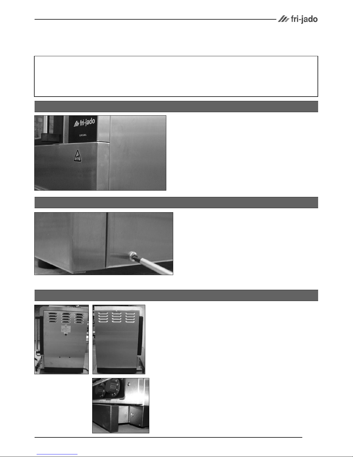
1. Remove the screws that secure the panel
to the frame.
2. Remove the panel.
3. Reverse the procedure to install.
1. Remove the screws that secure the panel to
the frame.
2. Remove the panel.
3. Reverse the procedure to install.
REMOVAL AND REPLACEMENT OF PARTS FOR THE TG50/TG110/TG330/TG550 H
RIGHT OR LEFT SIDE PANEL TG330/550
RIGHT SIDE PANEL TG110
1. Remove the screws on top and front side
(behind the drawer) that secure the panel to
the frame.
2. Remove the panel. Panel is hooked on back
panel with socket-head screw.
3. Reverse the procedure to install.
RIGHT OR LEFT SIDE PANEL TG50
Service Manual TG50/110/330/550 H form 9123660 rev. 04/2007
REMOVAL AND REPLACEMENT OF PARTS
Page 6
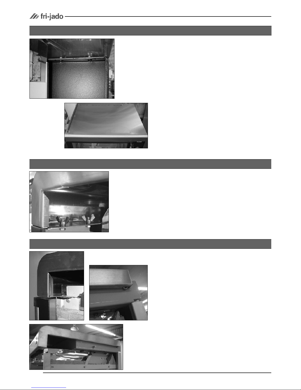
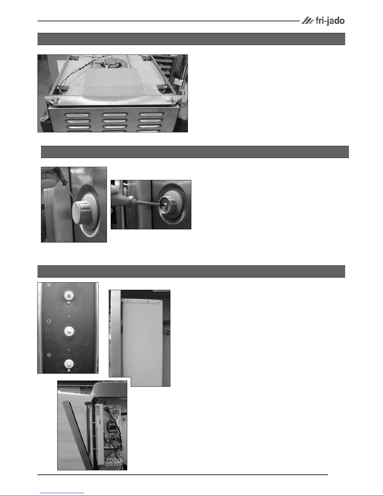
1. Remove the right side panel according prior
procedure.
2. Remove the 4 wing nuts and bolts on the
inside of the top cover.
3. Lift the top cover, slide it to the left and remove the cover.
4. Reverse the procedure to install.
TOP COVER TG110
1. Remove the right side panel according prior
procedure.
2. Remove the bolts and nuts on the inside of
the top cover.
3. Remove the screws on the top cover and
remove the cover.
4. Reverse the procedure to install.
TOP COVER TG330/550
1. Remove the right and left side panel according prior procedure.
2. Remove the nuts on the inside of the top cover.
3. Lift the top cover, while supporting the door,
over the hinge pin and remove the door.
4. Pull top cover towards yourself, lift this out of
the fixation with the socket-head screws and
remove the cover.
5. Reverse the procedure to install.
Note: Between the lower hinge pin and bearing
lies a washer.
TOP COVER TG50
Service Manual TG50/110/330/550 H form 9123660 rev. 04/2007
REMOVAL AND REPLACEMENT OF PARTS
Page 7
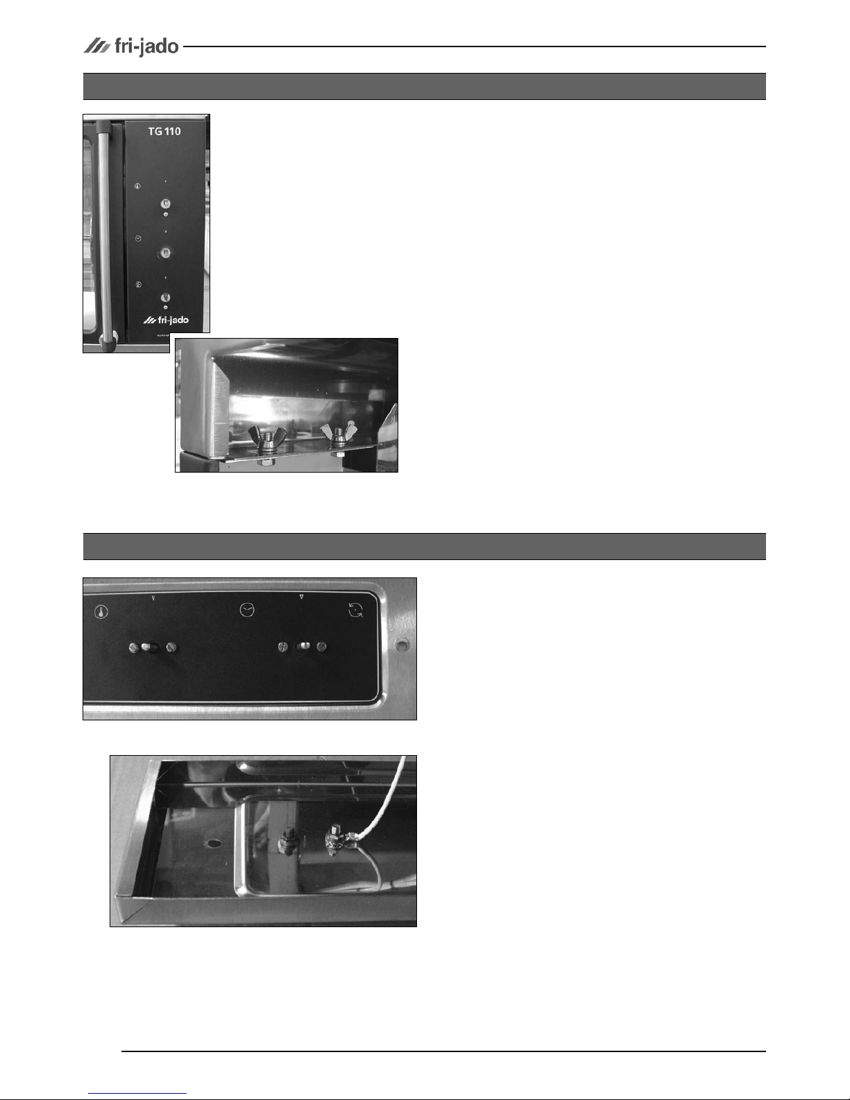
1. Remove cover plate on the knob with a
small screw driver.
2. Loosen the srew inside the knob.
3. Remove the knob with ring.
4. Reverse the procedure to install.
Note: check that the ring behind the knob is in
the right position and runs free from the panel.
KNOB
1. Remove the right side panel and the top cover according prior procedures.
2. Remove the wing nuts at the top of the left
side panel.
3. Allow the panel to slide down and remove it
from the unit.
4. Reverse the procedure to install.
LEFT SIDE PANEL TG110
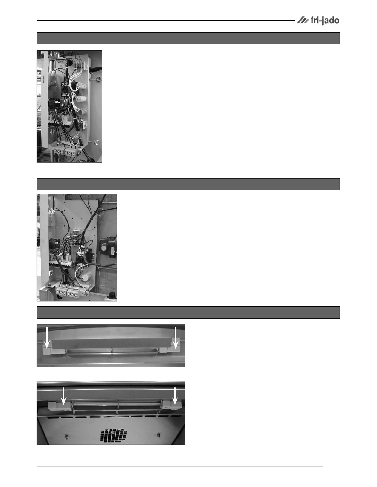
1. Remove the right side panel according prior
procedure.
2. Remove the knobs according prior procedure.
3. Remove the screws that secure the panel.
4. Loosen the wing nut from the cover box on
the electric panel and remove the box.
5. Remove the bolts and nuts on the backside
that secure the panel and remove the panel.
6. Reverse the procedure to install.
CONTROL PANEL TG330/550
Service Manual TG50/110/330/550 H form 9123660 rev. 04/2007
REMOVAL AND REPLACEMENT OF PARTS
Page 8
1. Remove the right side panel according prior
procedures.
2. Remove the knobs according prior procedures.
3. Remove the screws that secure the panel.
4. Remove the wing nuts and bolts on the backside that secure the panel and remove the
panel.
5. Reverse the procedure to install.
CONTROL PANEL TG110
1. Remove the fat drawer.
2. Remove the knobs according prior procedure.
3. Remove the screws that secure the front panel and remove the front panel.
4. Remove the 4 screws on the front side and
the nut on the back side and remove the
panel.
5. Reverse the procedure to install.
CONTROL PANEL TG50
Service Manual TG50/110/330/550 H form 9123660 rev. 04/2007
REMOVAL AND REPLACEMENT OF PARTS
Page 9
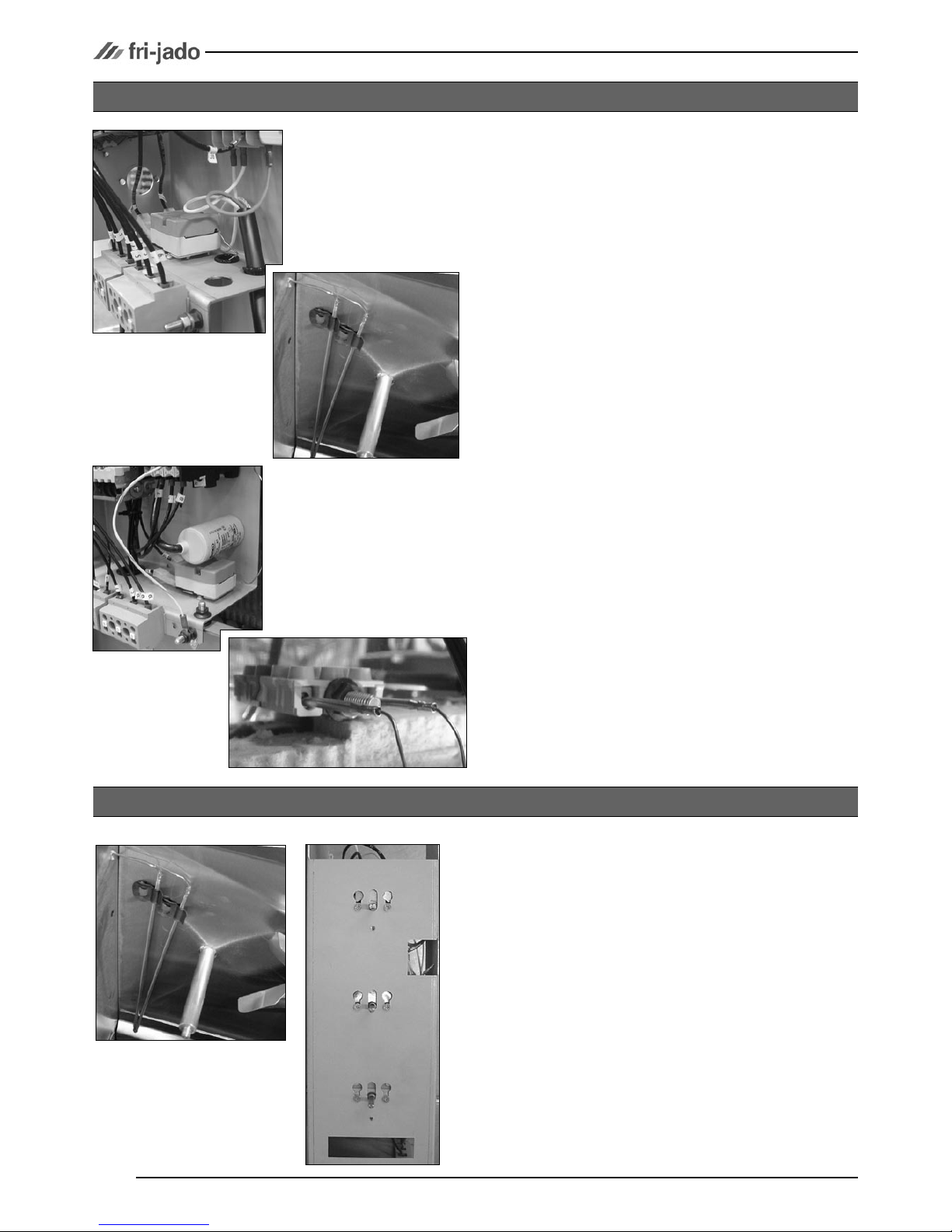
1. Remove the knobs according prior procedure.
2. Remove the screws on the front side that
secure the panel.
3. Remove the cover box on the electric panel
according prior procedure.
4. Disconnect all necessary wiring.
5. Remove the wing nuts that secure the electric
panel and slide panel to the right to remove
the panel.
6. Reverse the procedure to install.
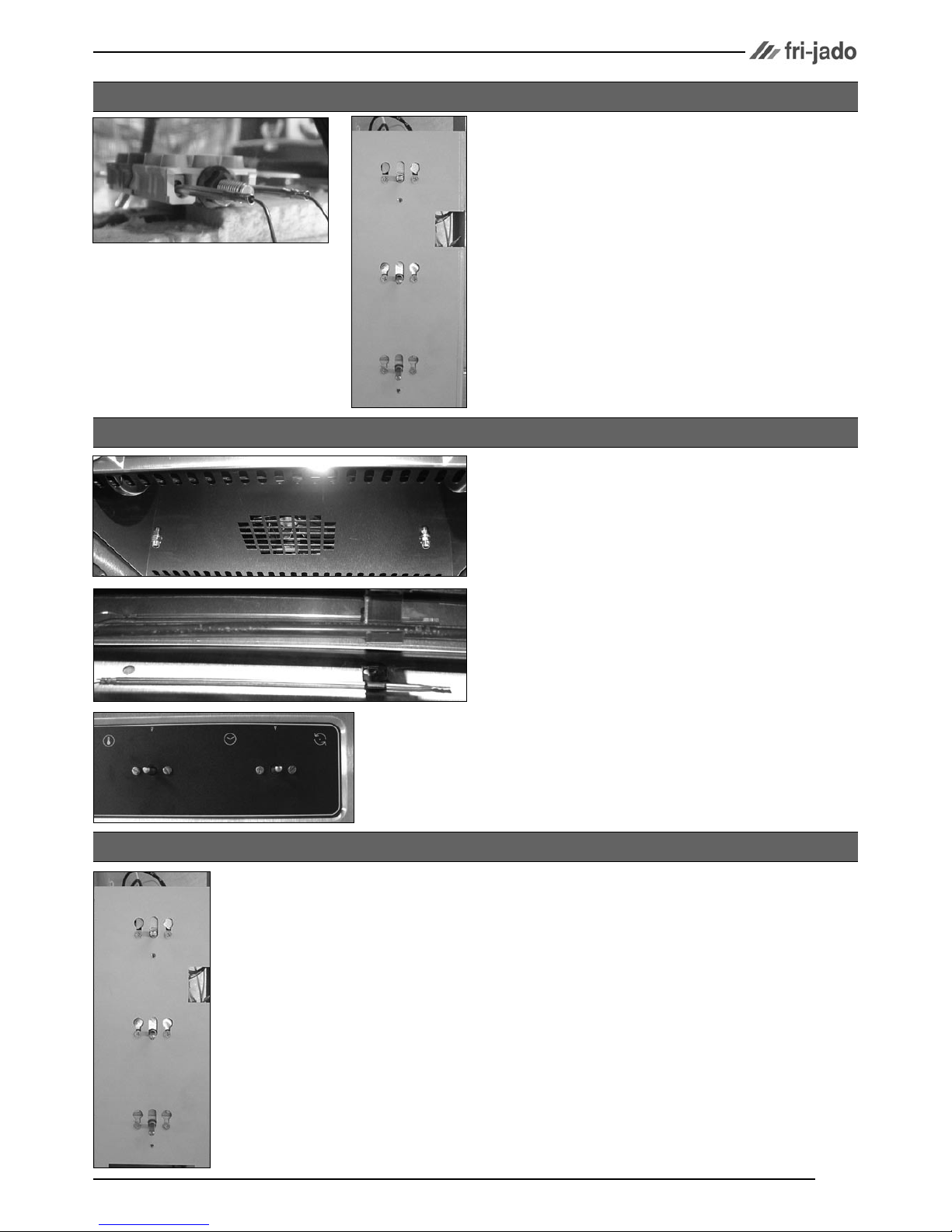
1. Remove the control panel according prior
procedure.
2. Disconnect all necessary wiring.
3. Remove the nuts that secure the electric panel
and remove the panel.
4. Reverse the procedure to install.
1. Remove the insulators of the lamp.
2. Remove the bolt from each end of the lamp
and remove the lamp.
3. Install the lamp with the painted side towards
the top of the oven. Hold the metal ends
when tightening the bolts to prevent the metal from twisting and damaging the lamp.
4. Tighten the insulators evenly to prevent damage.
ELECTRIC PANEL TG330/550
ELECTRIC PANEL TG110
QUARTZ LAMP
Caution: Do not touch the glass with your hands. The
moisture from your hands could affect the live span of the
lamp. This moisture can be removed with alcohol while the
lamp is cold.
Note: Use a clean rag or paper towel to replace the lamp.
TG330/550
TG110
Service Manual TG50/110/330/550 H form 9123660 rev. 04/2007
REMOVAL AND REPLACEMENT OF PARTS
Page 10
1. Remove the right side panel according prior
procedure.
2. (TG 330-550 only) Remove the suction and
fan plate on the inside of the oven.
3. (TG 110 only) Remove the nut on the clamp
and slide clamp towards yourself. Loosen the
screw in the clamp that secures the probe
and remove the probe.
4. (TG 330-550 only) Remove the thermostatprobe from the clip in the oven and guide it
outside through the opening in the side wall.
5. Remove the screws on the electric panel that
secure the thermostat.
6. Remove the thermostat and disconnect the
wiring.
7. Reverse the procedure to install.
Note: Set the new high limit thermostat to its
maximum position.
1. Remove the control panel cover and the
suction and fan plate according prior procedures.
2. Remove the thermostat-probe from the clip
in the oven and guide it outside through the
opening in the side wall.
3. Remove the screws on the electric panel that
secure the thermostat.
4. Remove the thermostat and disconnect the
wiring.
5. Reverse the procedure to install.
HIGH LIMIT THERMOSTAT
THERMOSTAT TG330/550
TG330/550
TG110
Service Manual TG50/110/330/550 H form 9123660 rev. 04/2007
REMOVAL AND REPLACEMENT OF PARTS
Page 11
1. Remove the control panel according prior
procedure.
2. Remove the nut on the clamp and slide
clamp towards yourself. Loosen the screw in
the clamp that secures the probe and remove
the probe.
3. Remove the screws on the electric panel that
secure the thermostat.
4. Remove the thermostat and disconnect the
wiring.
5. Reverse the procedure to install.
THERMOSTAT TG110
1. Remove the front panel and the left side panel according prior procedures.
2. Remove the cap nuts that secure the fan plate
and remove this plate.
3. Remove the thermostat-probe from the clip
in the oven and guide it outside through the
opening in the side wall.
4. Remove the screws on the control panel that
secure the thermostat.
5. Remove the thermostat and disconnect the
wiring.
6. Reverse the procedure to install.
THERMOSTAT TG50
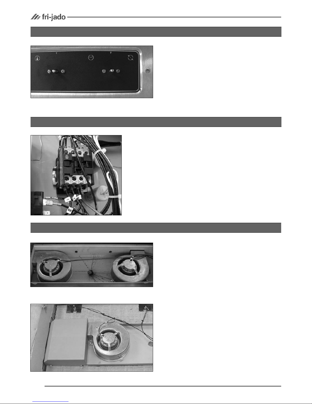
1. Remove the control panel according prior
procedure.
2. Remove the screws on the electric panel that
secure the switch.
3. Remove the switch and disconnect the wiring.
4. Reverse the procedure to install.
TIMER OR MAIN SWITCH
Service Manual TG50/110/330/550 H form 9123660 rev. 04/2007
REMOVAL AND REPLACEMENT OF PARTS
Page 12
1. Remove the right side panel and the top cover according prior procedures.
2. Remove the rotor discs, suction and fan plate
in the oven.
3. Remove the wing nut on the fan blade and
remove fan blade. (Left handed threads).
4. Disconnect wiring of the motor.
5. Remove the screws that secure the motor and
remove the motor.
6. Reverse the procedure to install.
Note: The blowers of TG 330-550 are equipped
with a capacitor. Check the direction of rotation
of the motor (clockwise) and change the wiring if
necessary.
BLOWER MOTOR
TG330/550
TG110
1. Remove the control panel according prior
procedure.
2. Remove the screws on the electric panel that
secure the timer.
3. Remove the timer and disconnect the wiring.
4. Reverse the procedure to install.
TIMER TG50
1. Remove the right side panel according prior
procedure.
2. Disconnect the lead wires to the switch.
3. Push down on the locking tab and lift out
and then up to remove it from the mounting
bracket.
4. Reverse the procedure to install.
CONTACTOR
Service Manual TG50/110/330/550 H form 9123660 rev. 04/2007
REMOVAL AND REPLACEMENT OF PARTS
Page 13
1. Remove the right side panel according prior
procedures.
2. Remove the rotor discs, suction and fan plate
in the bottom oven.
3. Remove the wing nut on the fan blade and
remove fan blade. (Left handed threads!)
4. Remove fat drawer from upper oven.
5. Remove the drip trays from the upper oven.
6. Remove the 4 screws that secure the intermediate plate above the blowers and slide this
plate off to the service side.
7. Disconnect wiring of the motor.
8. Remove the screws that secure the motor and
remove the motor.
9. Reverse the procedure to install.
Note: The blowers are equipped with a capacitor. Check the direction of rotation of the motor
(clockwise) and change the wiring if necessary.
BLOWER MOTOR BOTTOM ROTISSERIE (TG550 ONLY)
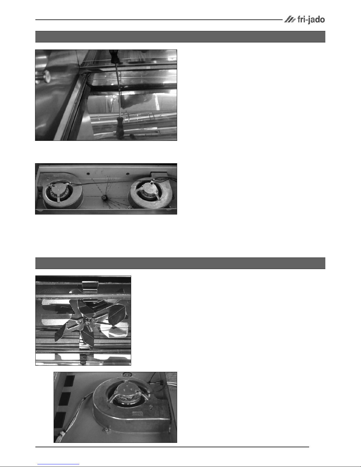
1. Remove the right and left side panel and the
top cover according prior procedures.
2. Remove the fan plate in the oven.
3. Remove the wing nut on the fan blade and
remove fan blade. (Left handed threads).
4. Disconnect wiring of the motor.
5. Remove the screws that secure the motor and
remove the motor.
6. Reverse the procedure to install.
BLOWER MOTOR TG50
Service Manual TG50/110/330/550 H form 9123660 rev. 04/2007
REMOVAL AND REPLACEMENT OF PARTS
Page 14
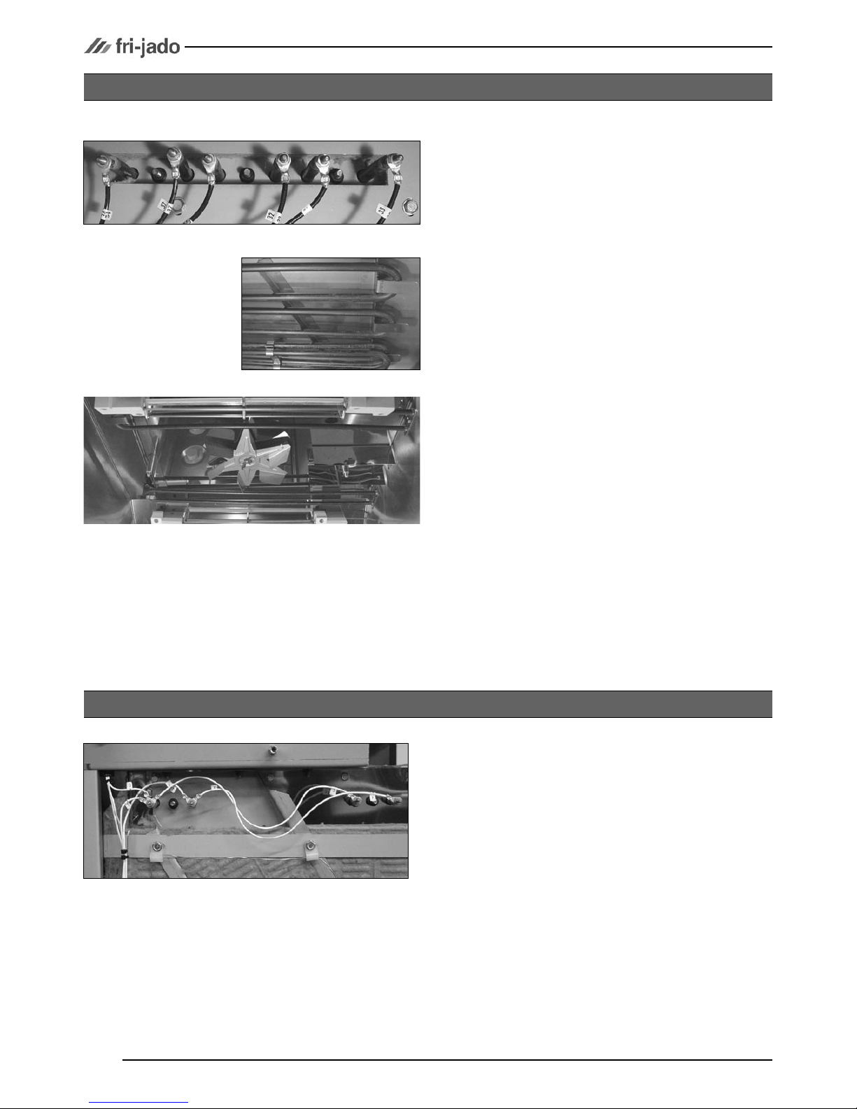
1. Remove the rotor discs, right side panel,
suction and fan plate according prior procedures.
2. Disconnect the wiring from the element.
3. Remove the mounting nut.
4. Remove the element from the mounting clip
and pull it from the wall.
5. Reverse the procedure to install.
HEATING ELEMENT TG110/330/550
TG330/550
TG110
1. Remove the left side panel and fan plate ac
-
cording prior procedures.
2. Disconnect the wiring from the element.
3. Remove the mounting nut.
4. Remove the element from the mounting clip
and pull it from the wall.
5. Reverse the procedure to install.
HEATING ELEMENT TG50
Service Manual TG50/110/330/550 H form 9123660 rev. 04/2007
REMOVAL AND REPLACEMENT OF PARTS
Page 15
1. Remove the right side panel and rotor discs
according prior procedures.
2. Disconnect the wiring of the motor. Check
where the wire, marked A is connected.
3. Remove the screws that secure the fan cover
and remove the cover.
4. Set the drive arm in horizontal position
towards the service side. You can do this by
manual operation or by turning the fan blade
by hand.
5. Mark the position of the motor support with a
marker.
6. Remove the bolts that secure the motor and
the nuts that secure the motor support and
remove the motor.
7. Check the white Teflon ring. Replace if necessary.
8. Install the fan blade on the new motor.
9. Reverse the procedure to install.
Note: Always make a test run on maximum temperature to insure the motor is well mounted and
adjusted.
DRIVE MOTOR TG330/550
DRIVE MOTOR TG110
1. Remove the right side panel and rotor discs
according prior procedures.
2. Disconnect the wiring of the motor.
3. Remove the bolts that secure the motor and
remove the motor.
4. Check the white Teflon ring. Replace if necessary.
5. Reverse the procedure to install.
Note: Always make a test run on maximum temperature to insure the motor is well mounted and
adjusted.
Service Manual TG50/110/330/550 H form 9123660 rev. 04/2007
REMOVAL AND REPLACEMENT OF PARTS
Page 16
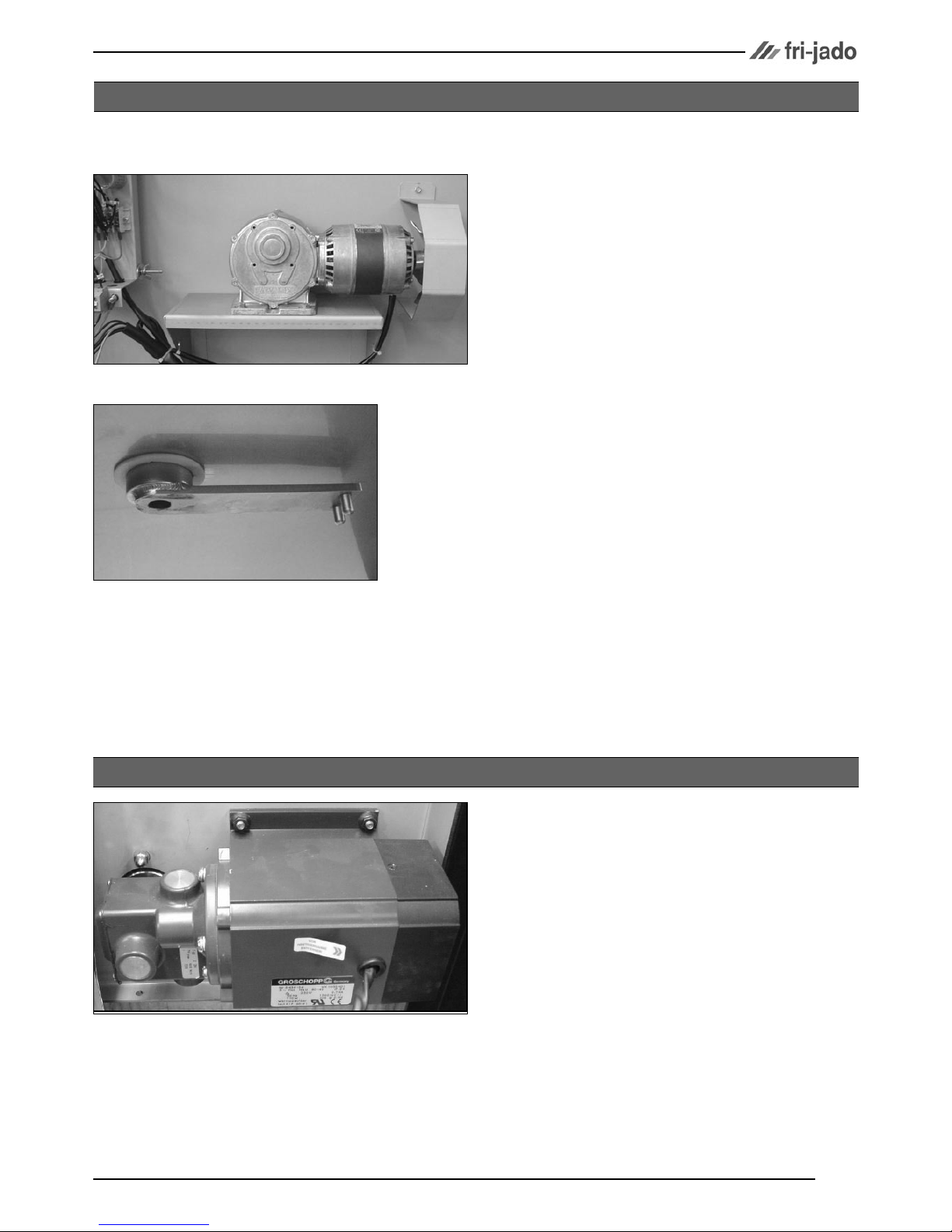
1. Open the door and loosen the bolts on top
side that secure the hinge plate.
2. Adjust the hinge and tighten the bolts.
DOOR ADJUSTMENT TG330/550
1. Remove the left side panel according prior
procedure.
2. Remove the screws that hold the back panel
and remove this panel.
3. Remove the 4 screws on the bottom side that
secure the motor.
Note: If necessary release the tension on the chain.
5. Measure how far the toothed wheel is mounted on the motor shaft.
6. Loosen the socket-head bolt that secures the
toothed wheel and remove this wheel.
7. Remove the key from the motor shaft.
8. Disconnect the wiring of the motor and
remove the motor. Check where the wire,
marked A, is connected.
9. Reverse the procedure to install.
Note: Always make a test run on maximum temperature to insure the motor is well mounted and adjusted.
DRIVE MOTOR TG50
Service Manual TG50/110/330/550 H form 9123660 rev. 04/2007
REMOVAL AND REPLACEMENT OF PARTS
Page 17
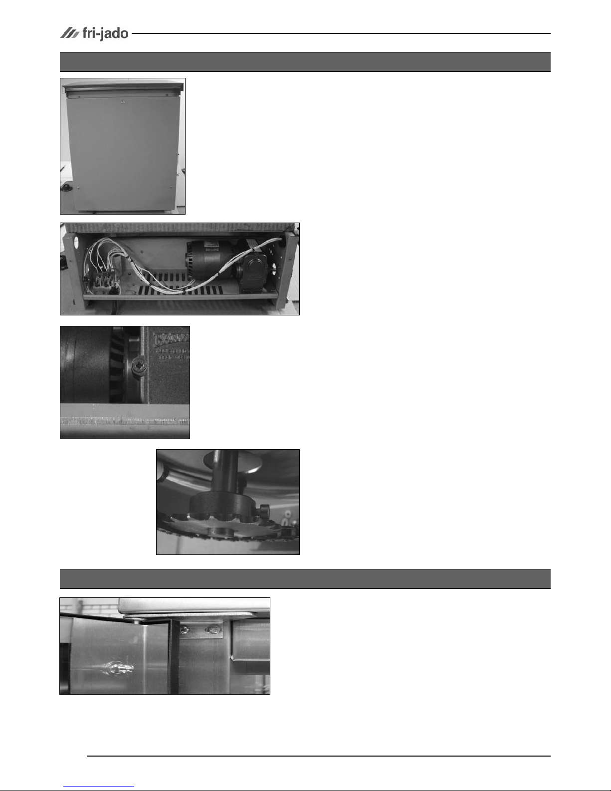
1. Remove the left side panel according prior
procedure.
2a. Loosen the 2 bolts on the hinge to adjust the
door in horizontal way.
2b. Loosen the 4 bolts on the reinforcement
plate to adjust the door in the depth.
3. Reverse the procedure to install.
DOOR ADJUSTMENT TG110
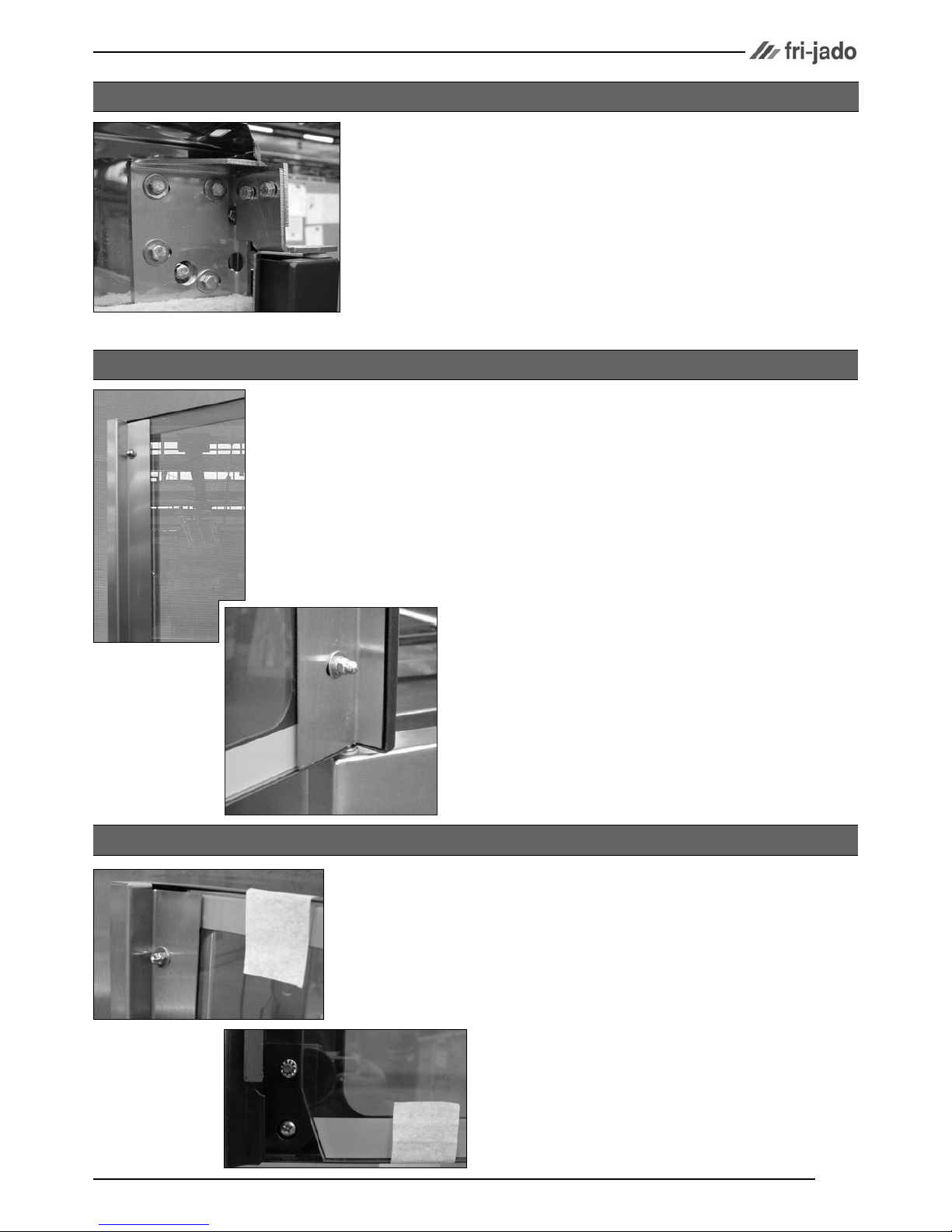
1. Secure the window by means of adhesive
tape.
2. Remove the retaining strip from the handle
edge.
3. Remove the screw that secures the holder for
the handle on the bottom side and remove
the holder and handle.
4. Reverse the procedure to install.
CHANGING HANDLE OF DOOR
1. Remove the retaining strip from the handle
edge while supporting the glass.
3. Loosen the nuts of the retaining strip on the
hinge side of the door and remove the glass.
4. Install the glass with the painted strips to the
outside of the unit due to the reflective coating on the inside of the glass.
5. Install the retaining strip on the handle side
of the door and tighten the nuts.
6. Adjust door if necessary as described under
“door adjustment”.
DOOR GLASS
 Loading...