

Fri-Jado TDR 5 M, TDR 7 M, TDW 7 M, TDW 5 M Service Manual
SERVICE MANUAL
TDR - ROTISSERIE OVEN MODELS
TDW - WARMER MODELS
MODELS
TDR 5 M
TDR 7 M
TDW 5 M
TDW 7 M
Model TDR 5 M Model TDR 7 M
- NOTICE -
This manual is prepared for the use of trained Service Technicians
and should not be used by those not properly qualified. If you
have attended training for this product, you may be qualified to
perform all the procedures in this manual.
This manual is not intended to be all encompassing. If you have
not attended training for this product, you should read, in its
entirety, the repair procedure you wish to perform to determine
if you have the necessary tools, instruments and skills required to
perform the procedure. Procedures for which you do not have the
necessary tools, instruments and skills should be performed by a
trained technician.
Reproduction or other use of this Manual, without the express
written consent of Fri-Jado, is prohibited.
USA
WWW.FRIJADO.COM
Service Manual TDR5/7 TDW5/7 form 9123905 rev. 11/2014

Page 2
Service Manual TDR5/7 TDW5/7 form 9123905 rev. 11/2014
TABLE OF CONTENTS
Versions
Version Issue date
Remarks
dd/mm/yy
03/2012 01/03/2012 First release.
07/2012 01/07/2012 Both doors with handles. Universal electric connections.
12/2012 01/12/2012 TDW 5 and 7 added. Small adjustments.
05/2013 01/05/2013 TDR 5 and TDW 5 deeper version added as standard. Small adjust-
ments.
02/2014 01/02/2014 Small textual changes. Exploded views modified.
11/2014 01/11/2014 New bracket sensors and various updates.
Service Manual TDR5/7 TDW5/7 form 9123905 rev. 11/2014
Page 3

TABLE OF CONTENTS
INDEX
Index .......................................................................................................................................................... 4
General technical data
Technical data
Programming instructions for the TDR 5 - 7 and TDW 5 - 7
Removal and replacement of parts for the TDR 5 - 7
Right or left side panel
Top cover
Knob
................................................................................................................................................ 9
....................................................................................................................................................... 9
Operating panel
Electric panel
........................................................................................................................................ 10
Replacing a lamp
Infra-red halogen lamp holder
Main switch or timer
.............................................................................................................................. 6
....................................................................................................................................... 6
.................................................................. 7
............................................................................. 9
.......................................................................................................................... 9
................................................................................................................................... 10
................................................................................................................................. 10
........................................................................................................... 11
........................................................................................................................... 11
Infra-red halogen lamp holder bottom rotisserie (stacked TDR)
High limit thermostat
Thermostat
Door switch
Contactor
Rotor switch
Blower motor
........................................................................................................................................... 13
.......................................................................................................................................... 14
.............................................................................................................................................. 14
......................................................................................................................................... 14
....................................................................................................................................... 15
Blower motor bottom rotisserie (stacked TDR)
Drive motor
.......................................................................................................................................... 17
Heating element
Door adjustment (left side)
Door inside
Door outside
........................................................................................................................................... 19
........................................................................................................................................ 19
.......................................................................................................................... 13
................................................................................. 16
.................................................................................................................................. 18
................................................................................................................. 18
...................................................... 12
Removal and replacement of parts for the TDW 5 and TDW 7
Blower motor
Thermometer
Thermostat
Main switch
Heating element
Halotherm lamp
Electrical tests and service procedures
Heating element test
Contactor, drive motor and blower test
Control location
....................................................................................................................................... 20
....................................................................................................................................... 20
........................................................................................................................................... 21
.......................................................................................................................................... 21
.................................................................................................................................. 22
................................................................................................................................... 22
.................................................................................................. 23
........................................................................................................................... 23
............................................................................................. 23
................................................................................................................................... 24
........................................................... 20
Page 4
Service Manual TDR5/7 TDW5/7 form 9123905 rev. 11/2014

TABLE OF CONTENTS
General troubleshooting list .................................................................................................................. 25
Troubleshooting for the TDR 5 and 7 rotisseries
Troubleshooting for the TDW 5 and 7 warmers
............................................................................... 25
................................................................................ 26
Analytic troubleshooting list
Servicing and repairing the TDR 5 and 7 rotisseries
Servicing and repairing the TDW 5 and 7 warmers
Exploded views & part lists
TDR 5 M - sheet metal work
TDR 5 M - components
TDR 5 M - doors
................................................................................................................................... 36
TDR 7 M - sheet metal work
TDR 7 M - components
TDR 7 M - doors
................................................................................................................................... 42
TDW 5 M - sheet metal work
TDW 5 M - components
TDW 7 M - sheet metal work
TDW 7 M - components
Electrical diagrams
.................................................................................................................................. 52
................................................................................................................. 27
.......................................................................... 27
........................................................................... 30
.................................................................................................................... 32
................................................................................................................ 32
........................................................................................................................ 34
................................................................................................................ 38
........................................................................................................................ 40
.............................................................................................................. 44
....................................................................................................................... 46
.............................................................................................................. 48
....................................................................................................................... 50
Circuit diagram TDR 5 and 7 M, single and stacked unit
Wiring diagram TDR 5 and 7 M, single and stacked unit
Circuit diagram TDR 5 and 7 M, single and stacked unit
(untill serial number 100059841)
........................................................................................................ 54
Wiring diagram TDR 5 and 7 M, single and stacked unit
(untill serial number 100059841)
........................................................................................................ 55
Circuit diagram TDR 5 and 7 M, single and stacked unit
(untill serial number 100058736)
....................................................................................................... 56
Wiring diagram TDR 5 and 7 M, single and stacked unit
(untill serial number 100058736)
Circuit diagram TDW 5 M, single and stacked unit
Wiring diagram TDW 5 M, single and stacked unit
Circuit diagram TDW 7 M, single and stacked unit
Wiring diagram TDW 7 M, single and stacked unit
........................................................................................................ 57
........................................................................... 58
........................................................................... 59
........................................................................... 60
........................................................................... 61
.................................................................. 52
.................................................................. 53
.................................................................. 54
.................................................................. 55
.................................................................. 56
................................................................. 57
Service Manual TDR5/7 TDW5/7 form 9123905 rev. 11/2014
Page 5
GENERAL TECHNICAL DATA
GENERAL TECHNICAL DATA
This manual covers the TDR series rotisserie ovens and the TDW series warmers. Ovens and
warming cabinets come in two sizes. Ovens and warmers will also be delivered in stacked
versions.
• TDR 5 – Oven with 5 spits ( 15 to 20 chickens ) or 5 baskets ( 15 chickens ).
• TDR 7 - Oven with 8 spits ( 32 to 40 chickens ) or 7 baskets ( 28 chickens ).
• TDW 5 - Warming cabinet for 25 to 30 chickens.
• TDW 7 - Warming cabinet for 35 to 40 chickens.
All of the information, illustrations and specifications contained in this manual are based on
the latest product information available at the time of printing.
TECHNICAL DATA
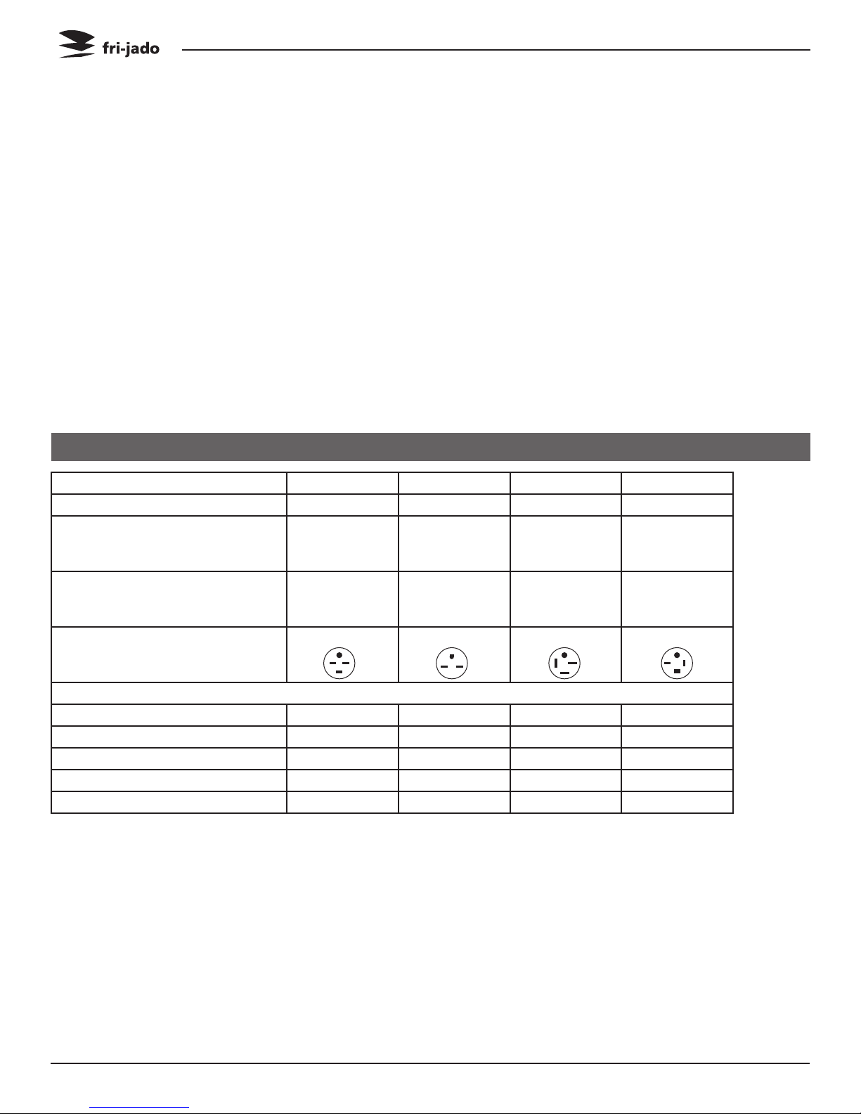
Type TDR 5 TDW 5 TDR 7 TDW 7
Power (W) 6600 2800 10500 3500
Fuses needed with power connection 208 V, 3 ~ 60 Hz
3x 20 A _ 3x 40 A 3x 20A
( 3 phases without zero )
Fuses needed with power connection 208 V, 1N ~ 60 Hz
_ 1x 15A _ _
( 1 phase with zero )
Standard plug from factory NEMA 15-30P NEMA 6-15P NEMA 15-50P NEMA 15-20P
G
Z
X
Y
G
G
Z
X
Y
G
Z
X
Y
Stacked cabinets: each cabinet comes with separate power cord!!
Net weight (lbs) 287 220 408 331
Gross weight (lbs) 335 265 476 388
Height (inch) 35 3/4” 35 3/4” 41 3/4” 41 3/4”
Width (inch) 33” 33” 39 1/4” 39 1/4”
Depth (inch) 30 3/8” 30 3/8” 35” 35”
• Standard set of tools.
• Metric wrenches, sockets and hex socket key wrenches.
• Multi-meter and AC current clamp meter.
• Temperature tester.
• Insulation value tester (Megger).
• Field Service Grounding Kit.
Service Manual TDR5/7 TDW5/7 form 9123905 rev. 11/2014Page 6
PROGRAMMING INSTRUCTIONS
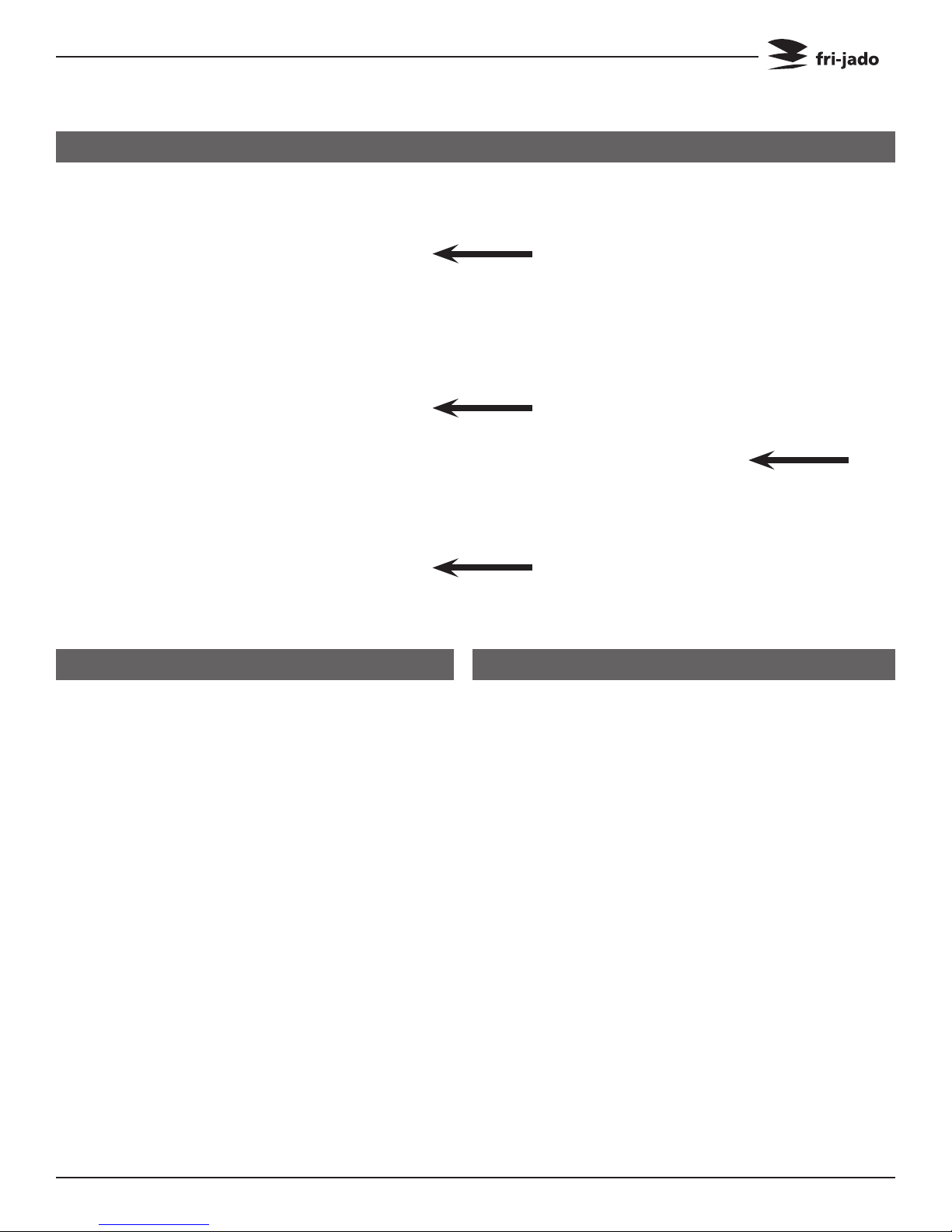
PROGRAMMING INSTRUCTIONS FOR THE TDR 5 - 7 AND TDW 5 - 7
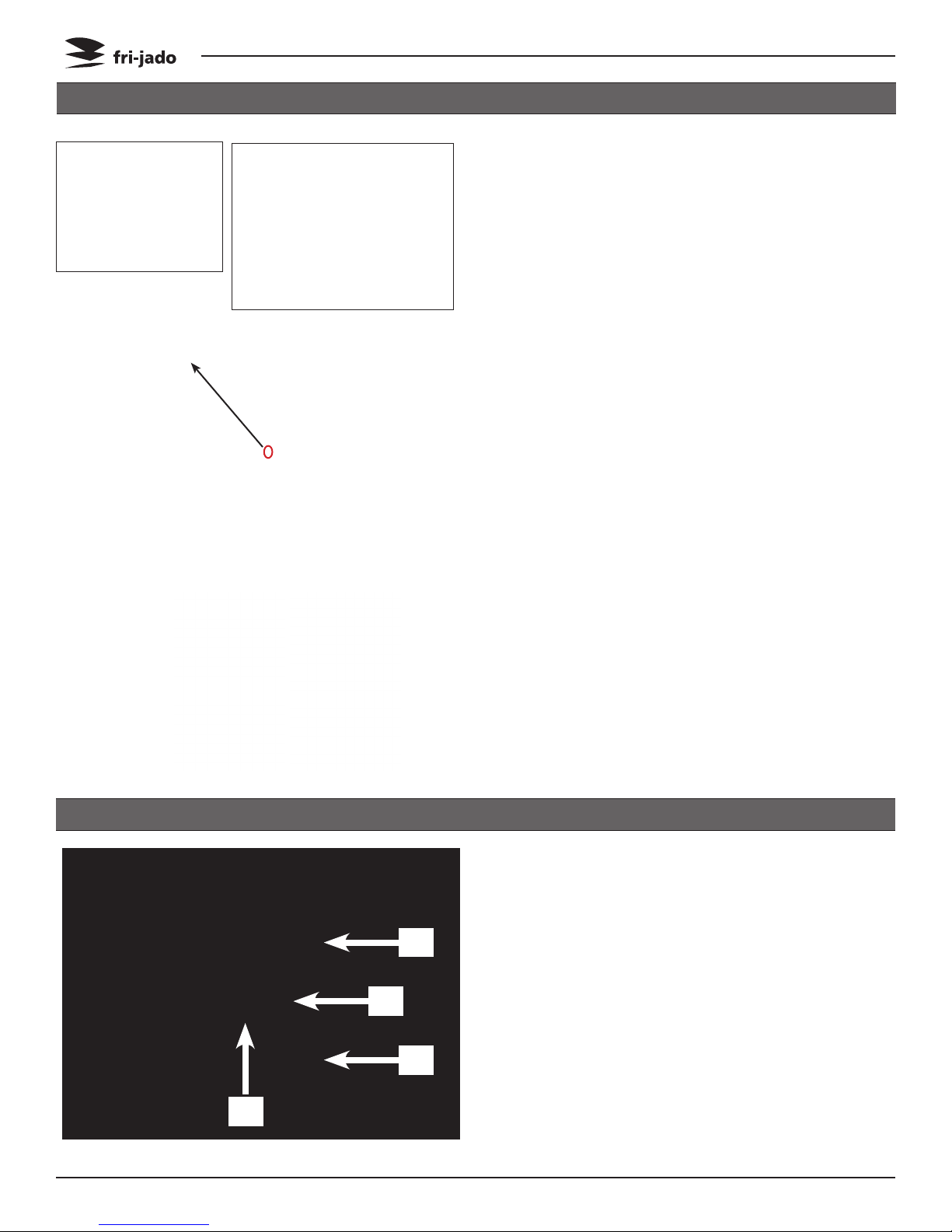
OPERATING PANEL
Temperature control
Timer
Rotor switch
SETTING THE TDR
1. Set the thermostat to
the desired temperature.
2. Set the timer to the desired time.
Main switch
LOADING WITH PRODUCTS
1. Set the main switch on 1.
2. Press the rotor switch.
Now the rotor will turn as
long as you press the rotor
switch.
Load the products inside
and press the rotor switch
again to turn the rotor.
3. Set the main switch on 1.
Service Manual TDR5/7 TDW5/7 form 9123905 rev. 11/2014
Page 7
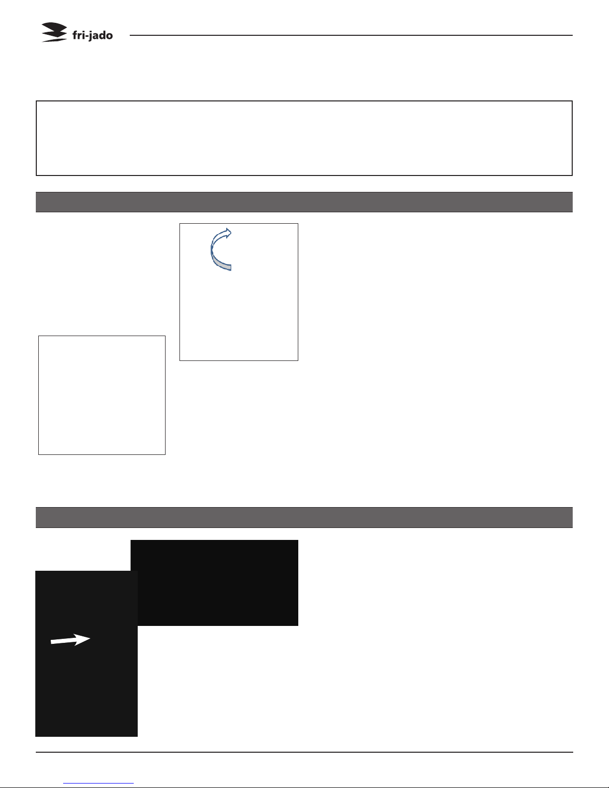
THERMOMETER °F
PROGRAMMING INSTRUCTIONS
SETTING THE TDW
0 = Off
1 = 25°C / 77°F
2 = 40°C / 104°F
3 = 60°C / 140°F
4 = 80°C / 176°F
5 = 95°C / 203°F
THERMOSTAT DIAL
Turn thermostat dial to desired temperature.
Page 8 Service Manual TDR5/7 TDW5/7 form 9123905 rev. 11/2014

REMOVAL AND REPLACEMENT OF PARTS
REMOVAL AND REPLACEMENT OF PARTS FOR THE TDR 5 - 8
WARNING: Disconnect the electrical power to the machine at
the main circuit box. Place a tag on the circuit box indicating
the circuit is being serviced.
RIGHT OR LEFT SIDE PANEL
1. Remove the crosshead screws that secure
the panel to the frame.
2. Remove the panel.
3. Reverse the procedure to install.
TOP COVER
1. Remove the left side panel according
prior procedure.
2. Remove the screws securing both large
and small top covers.
3. Remove the top cover. (Lift at right side
and remove to the left).
4. Reverse the procedure to install.
KNOB
1. Remove cover plate on the knob with a
small screw driver.
2. Loosen the screw inside the knob.
3. Remove the knob with ring.
4. Reverse the procedure to install.
Note: check that the knob is in the right position and runs free from the panel. Especially for
the timer knob, to avoid blocking of the clock!
Page 9Service Manual TDR5/7 TDW5/7 form 9123905 rev. 11/2014

REMOVAL AND REPLACEMENT OF PARTS
OPERATING PANEL
1. Remove the right side panel according
prior procedure.
2. Remove the knobs according prior procedure.
3. Remove the screws that secure the panel.
4. Remove the bolt, nut and ring on the top side
on the backside of the operating panel.
5. Pull the panel away from the top side.
6. Remove the backside of the rotor switch by
lifting the fastening clip with a small screwdriver.
7. Remove the panel.
8. Reverse the procedure to install.
ELECTRIC PANEL
1. Remove the operating panel according
prior procedure.
2. Remove on the front side the screws that
secure the panel.
3. Remove on the inside bottom of the electric
panel the bolt and nuts.
4. Disconnect the wiring.
5. Slide the electrical panel backwards.
6. Reverse the procedure to install.
REPLACING A LAMP
Page 10
Service Manual TDR5/7 TDW5/7 form 9123905 rev. 11/2014
REMOVAL AND REPLACEMENT OF PARTS
INFRA-RED HALOGEN LAMP HOLDER
Caution: Do not touch the glass with your hands.
The moisture from your hands could affect the
live span of the lamp. This moisture can be removed with alcohol while the lamp is cold.
Note: Use a clean rag or paper towel to replace
the lamp.
1. Remove the bolts that secure the protection
guard of the Halogen lamp and remove the
guard.
2. Push the lamp to either side and pull it down
to remove the lamp.
3. Remove the top cover according prior procedure.
4. Disconnect the wiring on the terminal block.
5. Remove the insulation above the light fixture.
6. Remove the bolts and nuts that secure the
light fixture and remove the light fixture.
7. Remove the screws that secure the lamp holder and remove the holder.
8. Reverse the procedure to install.
Note 1: Be sure that the “drop”on the lamp is
pointing downwards.
Note 2: Check the lamp refelcting shield and
replace this if corroded.
MAIN SWITCH OR TIMER
1. Remove the right side panel and operating
panel according prior procedures.
2. Loosen the screws on the electric panel that
secure the switch.
3. Remove the switch and disconnect the wiring.
4. Reverse the procedure to install.
Page 11Service Manual TDR5/7 TDW5/7 form 9123905 rev. 11/2014
REMOVAL AND REPLACEMENT OF PARTS
INFRA-RED HALOGEN LAMP HOLDER BOTTOM ROTISSERIE (STACKED TDR)
Warning: When replacing the lamp holder for
the TDR 5, the top rotisserie has to be removed.
Caution: Do not touch the glass with your
hands. The moisture from your hands could affect the live span of the lamp. This moisture can
be removed with alcohol while the lamp is cold.
Note: Use a clean rag or paper towel to replace
the lamp.
1. Remove the bolts that secure the protection
guard of the Halogen lamp and remove the
guard.
2. Push the lamp to either side and pull it
down to remove the lamp.
3. Remove the fat drawer and the drip trays
from the upper oven.
4. Remove the bolts that secure the intermediate plate and remove this plate.
5. Cut the sealant around the bottom plate
and remove this plate (see arrow).
6. Knock out the access plate to the light fixture and remove this plate.
7. Disconnect the wiring on the terminal block.
8. Remove the insulation above the light fixture.
9. Remove the screws that secure the lamp holder and remove the holder from the inside.
10. Reverse the procedure to install.
Page 12
Note 1: Be sure that the “drop”on the lamp is
on the bottom side.
Note 2: Clean all surfaces that have to be sealed. Seal off the bottom plate with a grease
resistant sealant.
Note 3: Check the lamp reflecting shield and
replace this if corroded.
Service Manual TDR5/7 TDW5/7 form 9123905 rev. 11/2014
TDR 5
TDR 5
TDR 7
TDR 7
REMOVAL AND REPLACEMENT OF PARTS
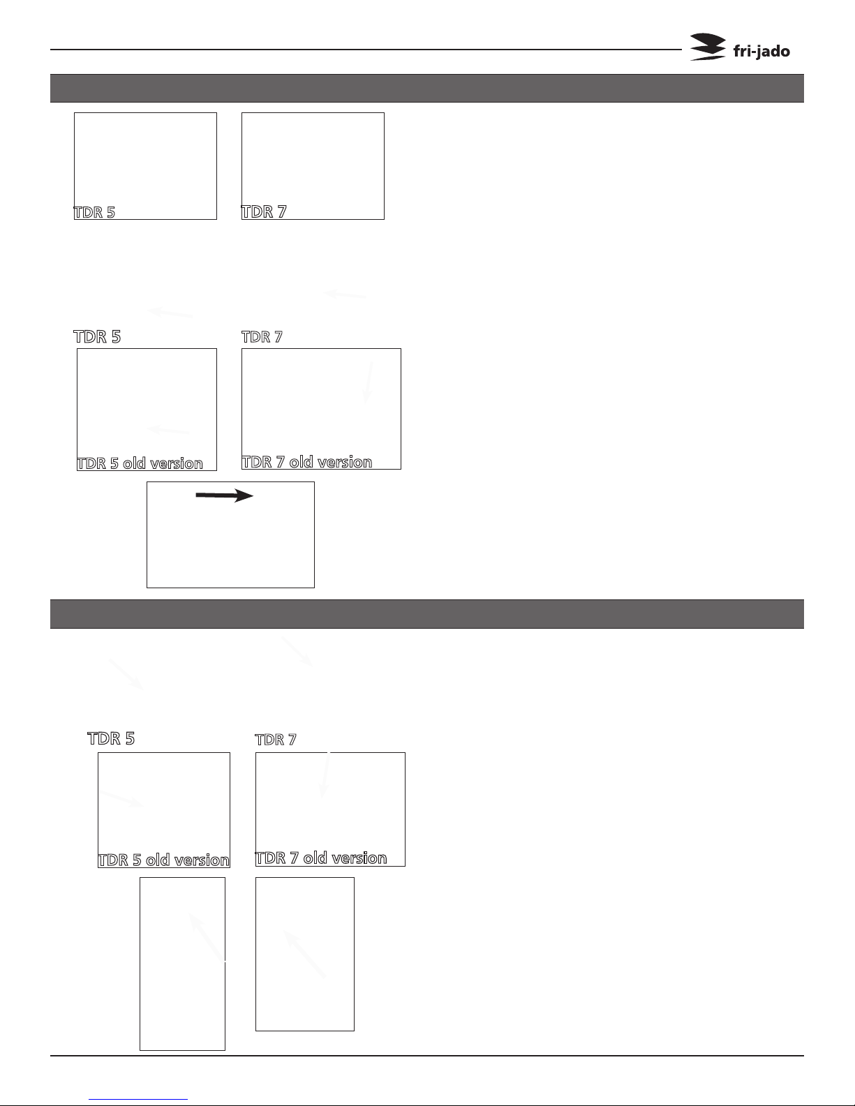
HIGH LIMIT THERMOSTAT
1. Remove the right side panel according prior
procedure.
2. Remove the fan plate on the ceiling on the
inside of the oven (this is only to check if the
probe is on the right place).
3. Remove the thermostat probe from the clip
and remove the probe.
4. Remove the screws on the electric panel that
secure the thermostat.
6. Remove the thermostat and disconnect the
wiring.
7. Reverse the procedure to install.
Note 1: The probe sticks out of the side wall till
TDR 5 old version
TDR 5
TDR 5 old version
TDR 7 old version
TDR 7
TDR 7 old version
the end of the bracket.
Note 2: Set the new high limit thermostat to its
maximum position.
Note 3: The versions until serial number
100067092 have different brackets. The latest
bracket is the prefered one.
THERMOSTAT
1. Remove the right side panel, operating panel
and fan plate on the inside of the oven according prior procedures.
2. Remove the thermostat probe from the clip and
remove the probe.
3. Loosen the 2 screws on the electric panel that
secure the thermostat.
4. Remove the thermostat and remove the wiring.
5. Reverse the procedure to install.
Note 1: The probe sticks out of the side wall till the
end of the bracket.
Note 2: The versions until serial number 100067092
have different brackets. The latest bracket is the
prefered one.
Page 13Service Manual TDR5/7 TDW5/7 form 9123905 rev. 11/2014
REMOVAL AND REPLACEMENT OF PARTS
DOOR SWITCH
1. Remove the right side panel according prior
procedure.
2. Remove the 2 screws that secure the switch
and remove the switch.
3. Disconnect the wiring of the switch.
4. Reverse the procedure to install.
Note: The contact pin of the switch must run
free through the chassis.
CONTACTOR
1. Remove the right side panel according prior
procedure.
2. Disconnect the lead wires to the contactor.
3. Push the locking tab down with a screw
driver and lift out to remove it from the
mounting bracket.
4. Reverse the procedure to install.
ROTOR SWITCH
1. Remove the right side panel according to
prior procedure.
2. Lift the locking tab with a screwdriver and
remove the back part of the switch.
3. Loosen the 2 screws that secure the front
part and remove this part by twisting it.
4. Disconnect the wiring.
5. Reverse the procedure to install.
Page 14
Note: Make sure the back part is clicked-on on
both sides.
Service Manual TDR5/7 TDW5/7 form 9123905 rev. 11/2014
REMOVAL AND REPLACEMENT OF PARTS
BLOWER MOTOR
1. Remove the right side panel and the top
cover according to prior procedures.
2. Remove the rotor discs and the fan plate on
the ceiling inside the oven.
3. Remove the nut and washer on the fan
blade and remove the fan blade with the
help of the puller.
4. Remove the 3 screws that secure the shaft
seal plate. Now replace the shaft seal and
shaft seal plate.
5. Disconnect the connector of the motor wiring and also the ground wire.
6. Remove the nuts that secure the motor and
remove the motor.
7. Remove the wiring of the capacitor and
change the capacitor.
8. Reverse the procedure to install.
Note 1: The puller is delivered with each new
blower.
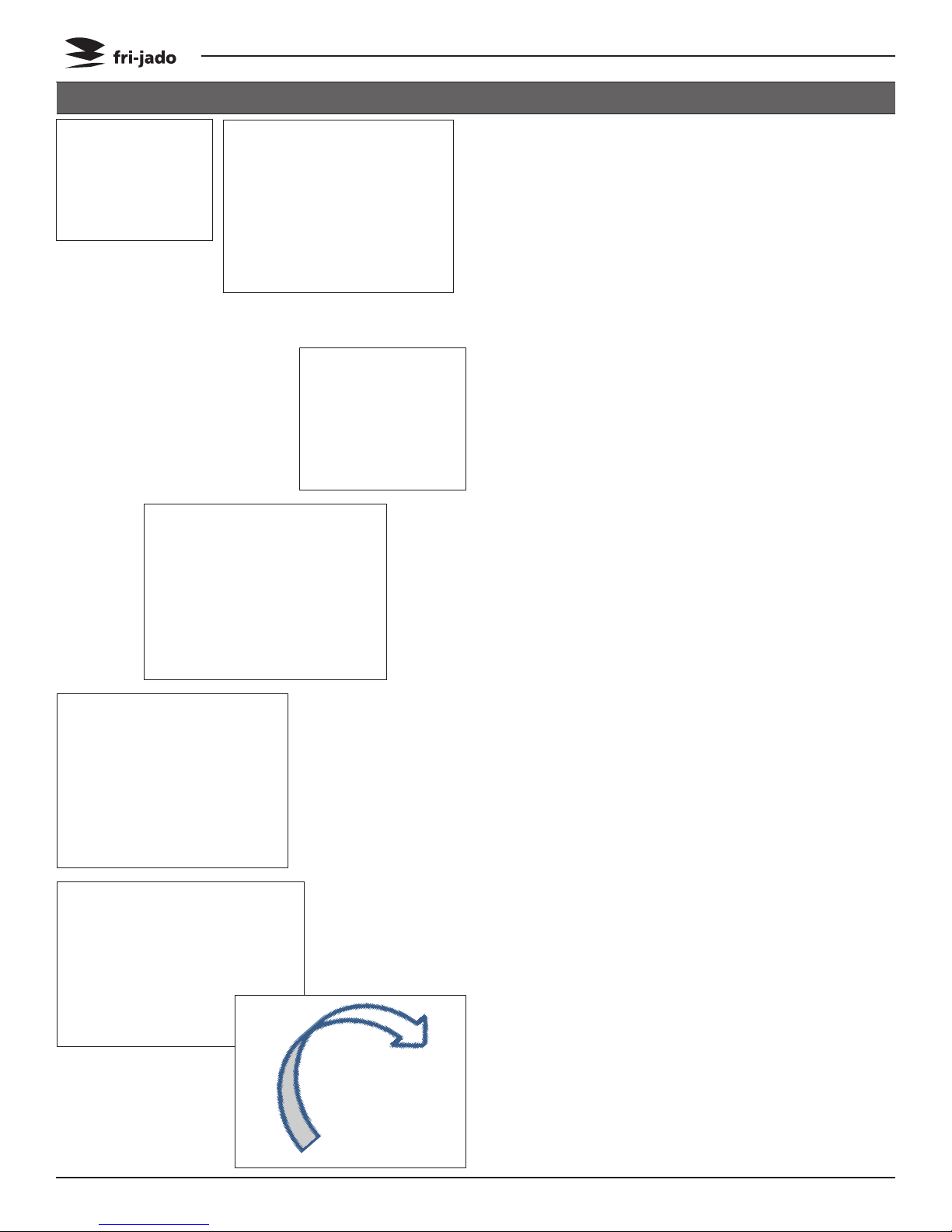
Note 2: The blower is equipped with a capacitor of 6 uF. Check the direction of rotation of
the motor (clockwise, see arrow).
Page 15Service Manual TDR5/7 TDW5/7 form 9123905 rev. 11/2014
REMOVAL AND REPLACEMENT OF PARTS
BLOWER MOTOR BOTTOM ROTISSERIE (STACKED TDR)
1. Remove the right side panel according prior
procedures.
2. Remove the rotor discs and the fan plate
on the ceiling inside the bottom oven.
3. Remove the nut and washer on the fan
blade and remove the fan blade with the
help of the puller.
4. Remove the 3 screws that secure the shaft
seal plate. Now replace the shaft seal and
shaft seal plate.
5. Remove the fat drawer and the drip trays
from the upper oven.
6. Remove the bolts that secure the intermediate plate and remove this plate.
7. Cut the sealant around the bottom plate
and remove this plate (see arrow).
8. Disconnect the connector of the motor wiring and also the ground wire.
9. Remove the nuts that secure the motor and
remove the motor.
10. Remove the wiring of the capacitor and
change the capacitor.
11. Reverse the procedure to install.
Note 1: The puller is delivered with each new
blower.
Note 2: The blower is equipped with a capacitor of 6 uF. Check the direction of rotation of
the motor (clockwise, see arrow).
Page 16
Note 3: Clean all surfaces that have to be sealed. Seal the bottom plate with a grease resistant sealant.
Service Manual TDR5/7 TDW5/7 form 9123905 rev. 11/2014
REMOVAL AND REPLACEMENT OF PARTS
DRIVE MOTOR
1. Remove the right side panel and rotor discs
according prior procedure.
2. Disconnect the wiring of the motor. Check
where the wire, marked A is connected.
3. Remove the screws that secure the fan cover
and remove the cover.
4. Note down how far the drive arm or drive
block sticks out from the inner wall (see white
or black arrow).
5. (TDR 5 only) Remove the nuts that secure the
motor and remove the motor.
6. (TDR 7 only) Set the drive arm in a position
vertical downwards. This can be done manually or by turning the fan blade by hand.
7. Mark the position of the motor support with
a marker.
8. (TDR 7 only) Remove the bolts that secure
the motor and the nuts that secure the motor
support and remove the motor.
9. Check the white Teflon ring. Replace this if
necessary.
10. Check the position of the red gasket between
motor support and the side wall. Replace this
if necessary.
11. Install the fan blade on the new motor.
12. Reverse the procedure to install.
Note: Always make a test run of 15 minutes on
maximum temperature to insure the motor is
well mounted and adjusted and turns parallel to
the side wall.
Page 17Service Manual TDR5/7 TDW5/7 form 9123905 rev. 11/2014
22
20
18
17
19
21
REMOVAL AND REPLACEMENT OF PARTS
HEATING ELEMENT
1. Remove the right side panel, the top cover
and the fan plate according prior procedures.
2. Remove the nut(s) on the inside top that fastens the element to the top side.
3. Disconnect the wiring from the element.
4. Cut the insulation on the top side around the
fastening plate of the elements and remove
the insulation.
5. Remove the nuts that secure the element and
remove the element and the gasket. Gasket
has to be replaced.
6. Reverse the procedure to install.
DOOR ADJUSTMENT (LEFT SIDE)
B
Page 18
C
A
A
1. Remove the left side panel according prior
procedure.
2. Loosen the nuts A of the upper hinge. The
door must be closed.
3. Loosen the locknut B and adjust the bolt C
in or out to adjust the door.
4. Tighten the nuts of the hinge and mount
the left-hand panel.
Service Manual TDR5/7 TDW5/7 form 9123905 rev. 11/2014

REMOVAL AND REPLACEMENT OF PARTS
DOOR INSIDE
1. Separate the inside door from the outside
door.
2. Lift the inside door upward out of the hinges.
3. Place the new door in the hinges.
4. Close the inside door on the outside door.
Note: Tightening of nuts max. 8 Nm. or
5.9 lbf.ft
DOOR OUTSIDE
1. Lift the inner door out of the hinges and lay
this aside.
2. Remove the left side panel according prior
procedure.
3. Remove the 2 nuts behind the upper hinge
and loosen the locknut according prior procedure. The door must be closed.
4. Hold the door on both sides and move this
towards yourself, before lifting it out of the
hinge on the bottom side. See to it that the
washers stay on the hinge.
Also remove the top hinge.
5. Place the top hinge on the new door.
6. Place the new door on the hinge on the
bottom side and push the 2 studs on the top
hinge through the openings on the top side
and screw the nuts on it .
7. Adjust the door according prior procedure.
Note: Tightening of nuts max. 8 Nm. or
5.9 lbf.ft
Page 19Service Manual TDR5/7 TDW5/7 form 9123905 rev. 11/2014
REMOVAL AND REPLACEMENT OF PARTS
REMOVAL AND REPLACEMENT OF PARTS FOR THE TDW 5 AND TDW 7
WARNING: Disconnect the electrical power to the machine at
the main circuit box. Place a tag on the circuit box indicating
the circuit is being serviced.
BLOWER MOTOR
1. Remove the right side panel according prior
procedure.
2. Remove the racks and bottom plate.
3. Remove the cap nuts that secure the fan
plate and remove fan plate.
4. Remove the wing nut on the fan blade and
remove fan blade. Left handed threads.
5. Disconnect wiring of the motor.
6. Remove the screws that secure the motor
and remove the motor.
7. Reverse the procedure to install.
Note: The blowers are equipped with a capacitor of 1.5 uF. Check the direction of rotation of
the motor (clockwise, see arrow) and change
the wiring if necessary.
THERMOMETER
1. Remove the right side panel and the fan
plate according prior procedures.
2. Remove the thermometer probe from the
clamp inside the cavity (see arrow) and
Page 20
guide it outside through the opening.
3. Remove the thermometer by pushing the
clamps “in”on both sides.
4. Reverse the procedure to install.
Service Manual TDR5/7 TDW5/7 form 9123905 rev. 11/2014
 Loading...