

Fri-Jado TDR 5 P eco, TDR 8 P eco, TDW 5 P, TWD 8 P Service Manual

WWW.FRIJADO.COM
Service Manual TDR5/8 P TDW5/8 P form 9123911 rev. 10/2014
SERVICE MANUAL
TDR P
eco
- ROTISSERIE OVEN MODELS
TDW - WARMER MODELS
- NOTICE -
This manual is prepared for the use of trained Service Technicians
and should not be used by those not properly qualified. If you
have attended a training for this product, you may be qualified to
perform all the procedures in this manual.
This manual is not intended to be all encompassing. If you have
not attended a training for this product, you should read, in its
entirety, the repair procedure you wish to perform to determine
if you have the necessary tools, instruments and skills required to
perform the procedure. Procedures for which you do not have the
necessary tools, instruments and skills should be performed by a
trained technician.
Reproduction or other use of this Manual, without the express
written consent of Fri-Jado, is prohibited.
MODELS
TDR 5 P
eco
TDR 8 P
eco
TDW 5 P
TDW 8 P
Model TDR 5 P
eco
Model TDR 8 P
eco

Page 2
Service Manual TDR5/8 P TDW5/8 P form 9123911 rev. 10/2014

Page 3
Service Manual TDR5/8 P TDW5/8 P form 9123911 rev. 10/2014
TABLE OF CONTENTS
Versions
Version Issue date
dd/mm/yy
Remarks
07/2012 01/07/2012 First release.
02/2013 01/02/2013 TDW 5 and 8 added. Small adjustments.
05/2013 01/05/2013 TDR 5 and TDW 5 deeper version added as standard. Small adjust-
ments.
09/2013 30/09/2013 Sizes for TDR 5 adapted in Technical data
01/2014 01/01/2014 Small textual changes. Exploded views and trouble shooting modi-
fied. Error 55 explanation added.
10/2014 01/10/2014 New bracket sensors, new errors, various updates.

Page 4
Service Manual TDR5/8 P TDW5/8 P form 9123911 rev. 10/2014
TABLE OF CONTENTS
Index .......................................................................................................................................................... 4
General technical data
.............................................................................................................................. 6
Technical data
....................................................................................................................................... 6
Programming instructions for the TDR 5 - 8 P and TDW 5 - 8
............................................................... 7
The automatic cook correction
........................................................................................................... 25
Removal and replacement of parts for the TDR 5 and TDR 8
.............................................................. 26
Right or left side panel
........................................................................................................................ 26
Top cover
.............................................................................................................................................. 26
Operating panel (general)
.................................................................................................................. 26
Electric panel
........................................................................................................................................ 27
Replacing a lamp
................................................................................................................................. 27
Operating panel, glass + backplate + keypad
.................................................................................... 27
Power and I/O board
........................................................................................................................... 28
CPU board
............................................................................................................................................ 28
Replacing of broken buzzer
................................................................................................................ 29
Keypad
.................................................................................................................................................. 29
Infra-red halogen lamp holder
........................................................................................................... 30
Infra-red halogen lamp holder bottom rotisserie (stacked TDR 8)
................................................... 31
Contactor
.............................................................................................................................................. 32
Relay for thermistor function blower (from ser.nr. 100067527)
....................................................... 32
Door switch
.......................................................................................................................................... 32
High limit thermostat
.......................................................................................................................... 33
PT 1000 sensor
...................................................................................................................................... 33
Blower motor
....................................................................................................................................... 34
Blower motor bottom rotisserie (stacked TDR)
................................................................................. 35
Drive motor
.......................................................................................................................................... 36
Heating element
.................................................................................................................................. 37
Door adjustment (left side)
................................................................................................................. 37
Door glass inside
.................................................................................................................................. 38
Door outside
........................................................................................................................................ 38
Removal and replacement of parts for the TDW 5 and TDW 8
........................................................... 39
Blower motor
....................................................................................................................................... 39
Thermometer
....................................................................................................................................... 39
Thermostat
........................................................................................................................................... 40
Main switch
.......................................................................................................................................... 40
Heating element
.................................................................................................................................. 41
Halotherm lamp
................................................................................................................................... 41
Parameter listing TDR P
.......................................................................................................................... 42
Introduction
......................................................................................................................................... 42
Reaching the parameter menus
.......................................................................................................... 42
Manager menu - description of the submenus
.................................................................................. 44
Service menu - description of the submenus
..................................................................................... 45
Adapting parameters
.......................................................................................................................... 47
Loading software
................................................................................................................................. 47
Read and store recipies in manager menu
......................................................................................... 48
Read and store recipies and parameters in service menu
................................................................. 49
INDEX

Page 5
Service Manual TDR5/8 P TDW5/8 P form 9123911 rev. 10/2014
TABLE OF CONTENTS
Parameter List P ................................................................................................................................... 51
Electrical tests and service procedures
.................................................................................................. 52
Heating element test
........................................................................................................................... 52
Contactor, drive motor and blower test
............................................................................................. 52
PT1000 sensor test
............................................................................................................................... 53
Error codes on display
......................................................................................................................... 53
Control location
................................................................................................................................... 54
General troubleshooting list
.................................................................................................................. 55
Troubleshooting for the TDR 5 and 8 rotisseries
............................................................................... 55
Troubleshooting for the TDW 5 and 8 warmers
................................................................................ 57
Error 55 explanation
............................................................................................................................ 58
Analytic troubleshooting list
................................................................................................................. 59
Servicing and repairing the TDR 5 and 8 rotisseries
.......................................................................... 59
Servicing and repairing the TDW 5 and 8 P warmers
........................................................................ 64
Exploded views & partlists
..................................................................................................................... 66
TDR 5 P - sheet metal work
................................................................................................................. 66
TDR 5 P - components
.......................................................................................................................... 68
TDR 5 P - doors
..................................................................................................................................... 70
TDR 8 P - sheet metal work
................................................................................................................. 72
TDR 8 P - components
.......................................................................................................................... 74
TDR 8 P - doors
..................................................................................................................................... 76
TDW 5 P - sheet metal work
................................................................................................................ 78
TDW 5 P - components
....................................................................................................................... 80
TDW 8 P - sheet metal work
................................................................................................................ 82
TDW 8 P - components
........................................................................................................................ 84
Electrical diagrams
.................................................................................................................................. 86
Circuit diagram TDR 5 and 8 P
........................................................................................................... 86
Wiring diagram TDR 5 and 8 P
........................................................................................................... 87
Circuit diagram TDR 5 and 8 P (untill serial number 100067527)
..................................................... 88
Wiring diagram TDR 5 and 8 P (until serial number 100067527)
..................................................... 89
Circuit diagram TDR 5 P (until 01-07-2012)
........................................................................................ 90
Circuit diagram TDR 8 P (until 01-07-2012)
........................................................................................ 91
Wiring diagram TDR 5 and 8 P (until 01-07-2012)
............................................................................ 92
Circuit diagram TDR 5 + 5 P bottom unit (until 01-07-2013)
............................................................ 93
Circuit diagram TDR 8 + 8 P bottom unit (until 01-07-2012)
............................................................ 94
Wiring diagram TDR 5 + 5 and 8 + 8 P bottom unit (until 01-07-2012)
.......................................... 95
Circuit diagram TDR 5 P
with TDW 5 (until 01-07-2012) ................................................................... 96
Wiring diagram TDR 5 P
with TDW 5 (until 01-07-2012) .................................................................. 97
Circuit diagram TDW 5
........................................................................................................................ 98
Wiring diagram TDW 5
........................................................................................................................ 99
Circuit diagram TDW 8
...................................................................................................................... 100
Wiring diagram TDW 8
...................................................................................................................... 101
Service Manual TDR5/8 P TDW5/8 P form 9123911 rev. 10/2014
Page 6
GENERAL TECHNICAL DATA
GENERAL TECHNICAL DATA
This manual covers the TDR P
eco
series rotisserie ovens and the TDW series warmers. Ovens
and warming cabinets come in two sizes. Ovens and cabinets will alsobe delivered in stacked
versions.
• TDR 5 – Oven with five spits ( 15 to 20 chickens )
• TDR 8 – Oven with eight spits ( 32 to 40 chickens )
• TDW 5 - Warming cabinet for 25 to 30 chickens
• TDW 8 - Warming cabinet for 35 to 40 chickens
All of the information, illustrations and specifications contained in this manual are based on
the latest product information available at the time of printing.
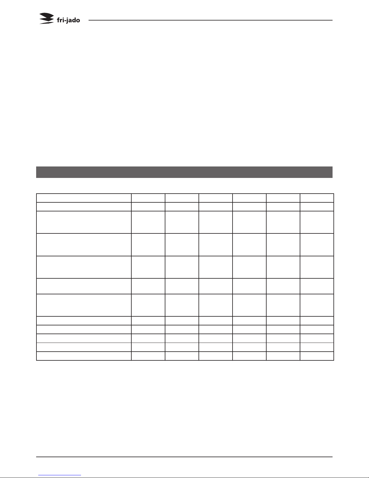
Type TDR 5 TDRW 5 TDR 8 TDRW 8 TDW 5 TDW 8
Power (W) 6600 9400 10500 14000 2800 3500
Fuses needed with power connection 400 V, 3N ~50…60 Hz
( 3 phases with zero )
3x 16 A 3x 16 A 3x 16 A 3x 32 A - -
Fuses needed with power connection 200 or 230 V, 3 ~50…60 Hz
( 3 phases without zero )
3x 20A 3x 32 A 3x 32 A 3x 35 A - -
Fuses needed with power connection 230 V, 1N ~50…60 Hz
( 1 phase with zero )
- - - - 1x 16 A 1x 16 A
Standard plug from factory 5-pole
Acc IEC309 and CEE-form
16 A
3P+N+E
16 A
3P+N+E
16 A
3P+N+E
32 A
3P+N+E
- -
Standard plug from factory single
pole
_ _ _ _ 2-pole
earthed
plug 16 A
2-pole
earthed
plug 16 A
Net weight (kg) 130 235 185 340 100 150
Gross weight (kg) 160 275 216 390 120 176
Height (mm) 910 1790 1065 2095 910 1065
Width (mm) 835 835 995 995 835 995
Depth (mm) 710 710 830 830 710 830
• Standard set of tools.
• Metric wrenches, sockets and hex socket key wrenches.
• Multi-meter and AC current clamp meter.
• Temperature tester.
• Insulation value tester (Megger).
• Field Service Grounding Kit.
TECHNICAL DATA
Service Manual TDR5/8 P TDW5/8 P form 9123911 rev. 10/2014
Page 7
PROGRAMMING INSTRUCTIONS
PROGRAMMING INSTRUCTIONS FOR THE TDR 5 - 8 P AND TDW 5 - 8
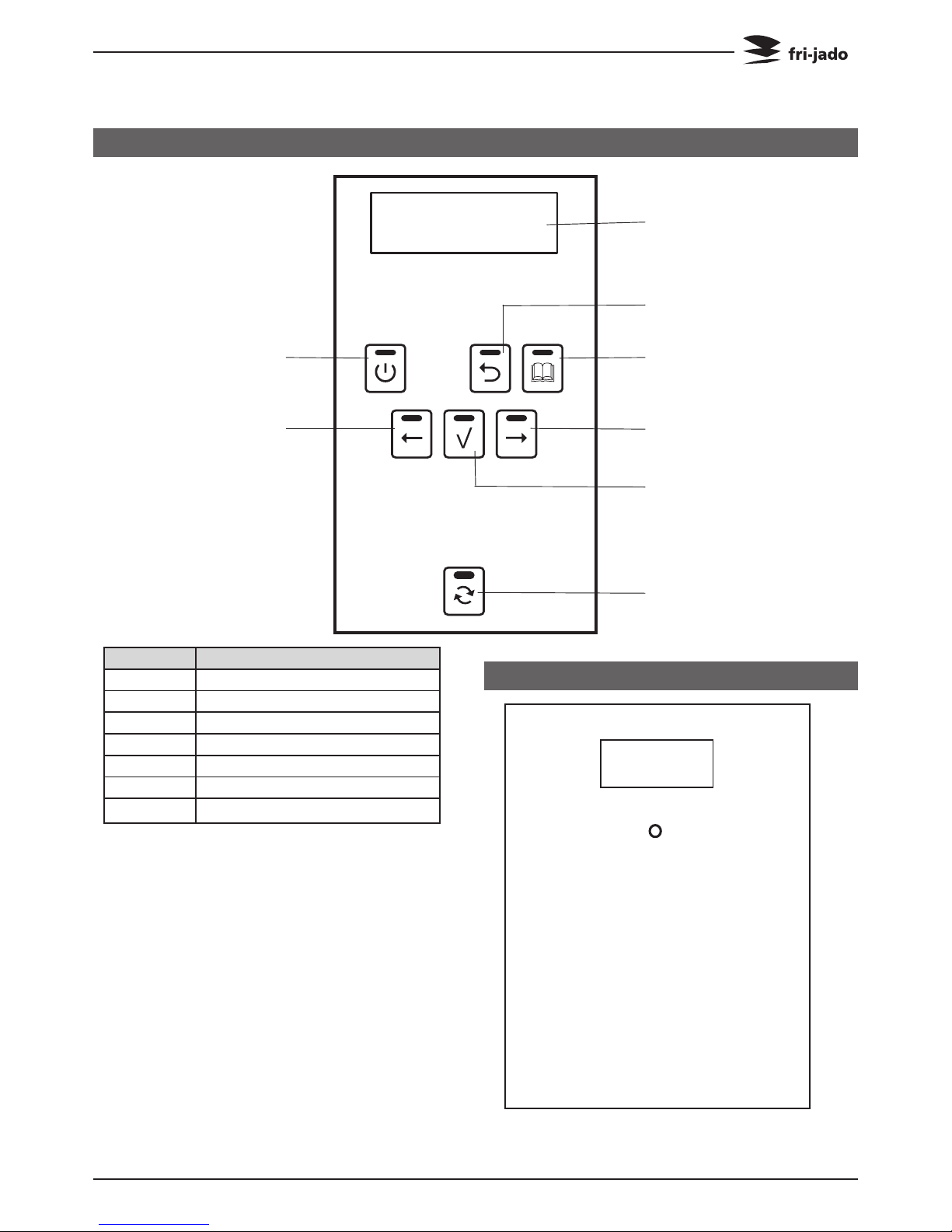
OPERATING PANEL
CHICKEN
85 1
2 3 7
Display
On / Off
Rotor
OK
Forward
List
Undo
Back
Key Function
On / Off Switching the unit On / Off
Undo Go back to previous menu
List Recipe / programming modus
Forward One step ahead in setting
Rotor Switching the rotor on
OK Acknowledge a function or change
Back One step back in setting
OPERATING PANEL WARMER
0 = Off
1 = 25°C / 77°F
2 = 40°C / 104°F
3 = 60°C / 140°F
4 = 80°C / 176°F
5 = 95°C / 203°F
Thermometer °C
Thermostat dial
Page 8
Service Manual TDR5/8 P TDW5/8 P form 9123911 rev. 10/2014
PROGRAMMING INSTRUCTIONS
OPERATION
TDR-P
eco
Models
Interface P Eco
TDR
Version x.x.x
Drumstick
Chicken
98 99 1 2 3
180°C Preheat
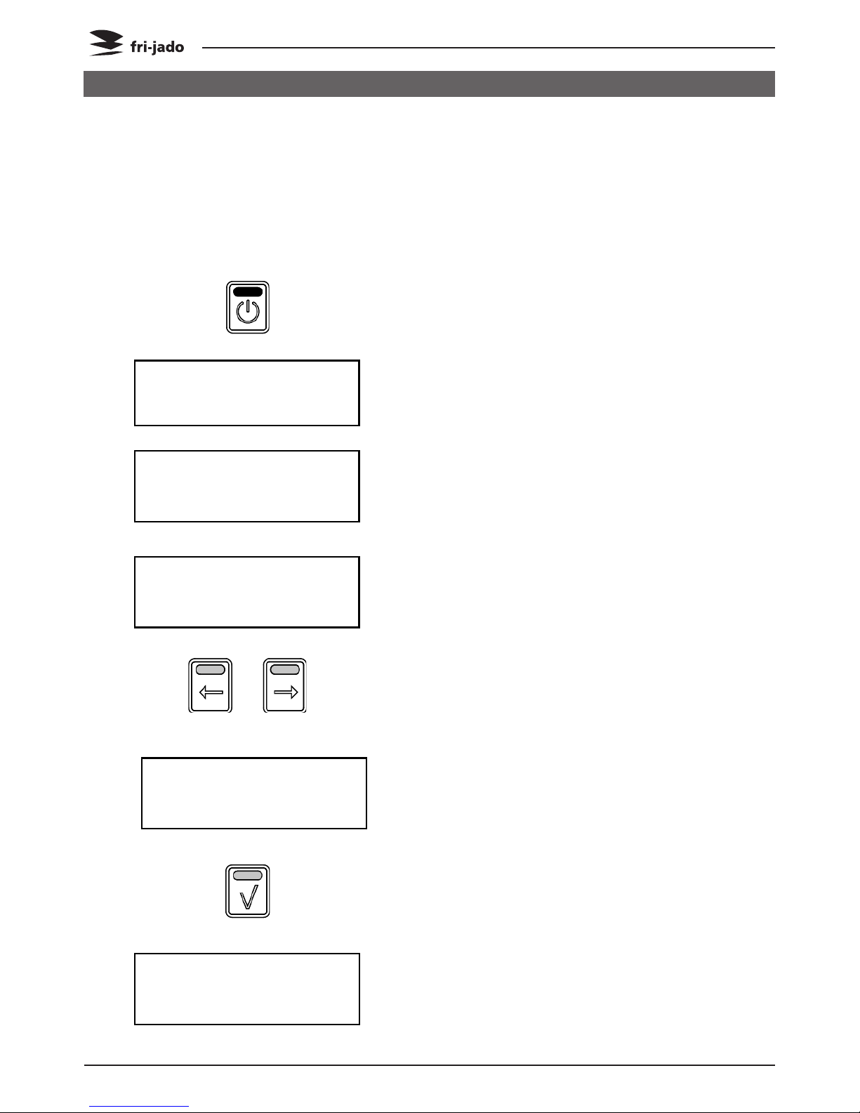
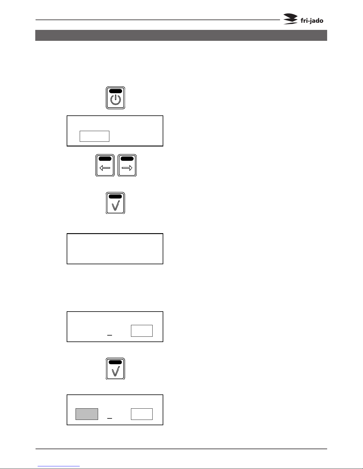
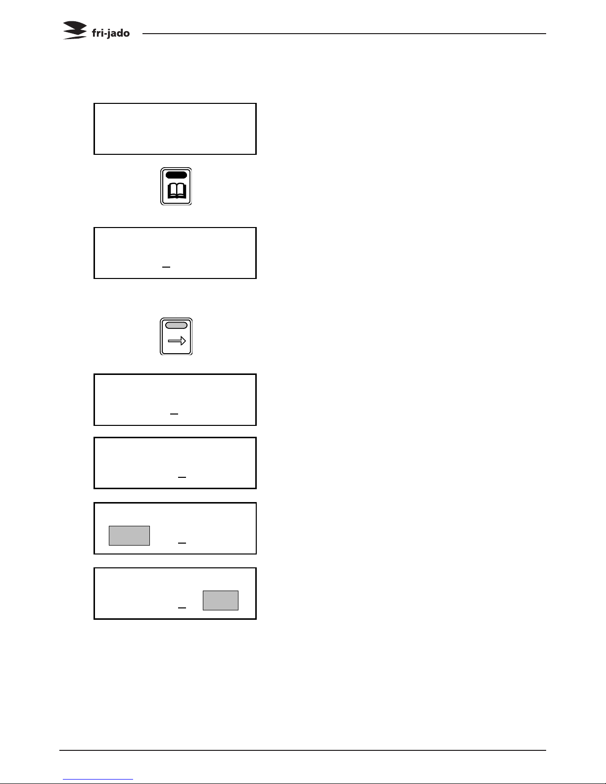
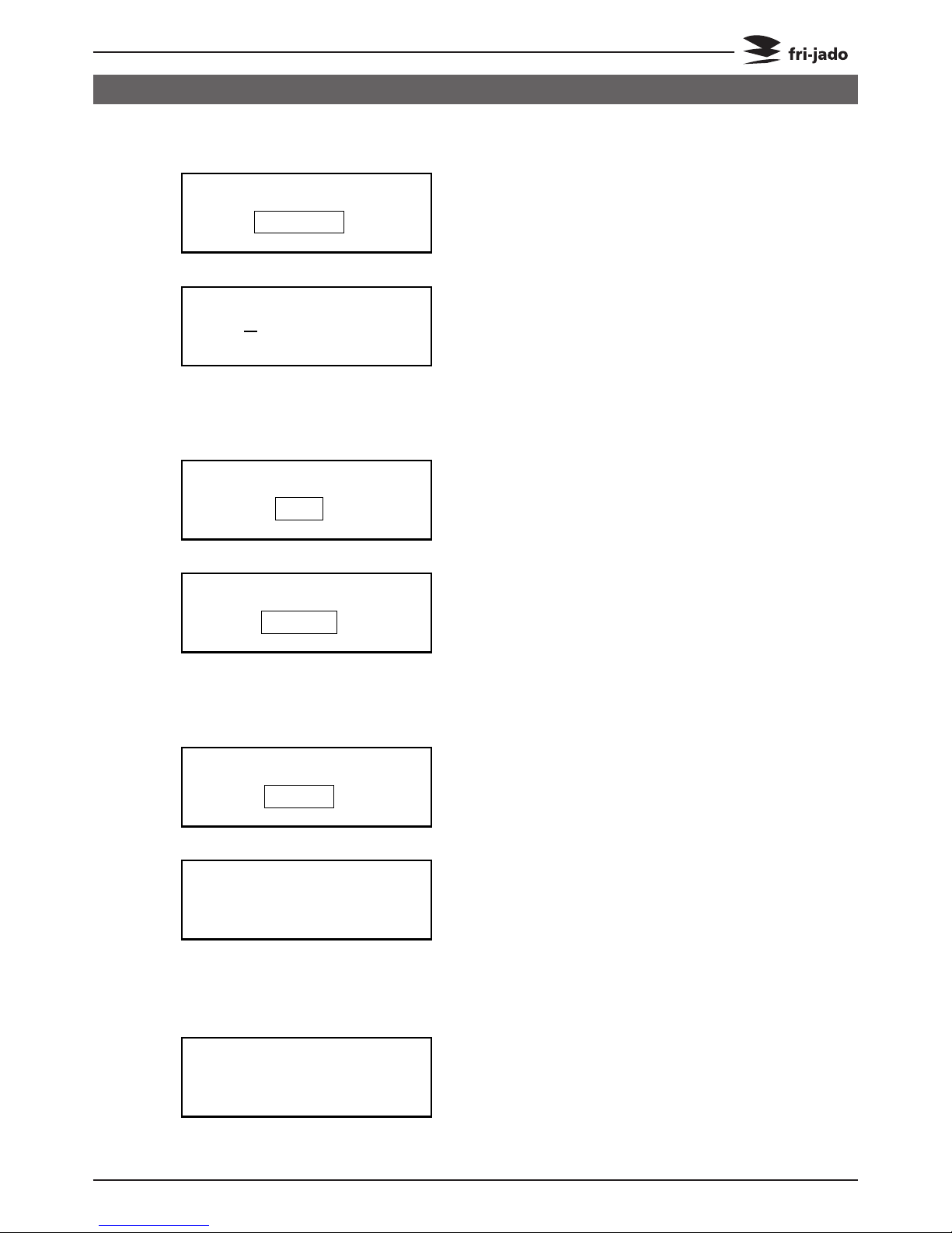
5. OPERATION
Buttons are lit when functional.
5.1. Operation of the rotisserie
1. Press Start.
2. Display shows Fri-Jado logo.
3. Display shows software version.
4. Display shows latest cooking
program.
5. Use the arrow buttons for program
selection.
6. Display shows selected program.
7. Confirm the selected program.
8. Display shows pre-heat
(only when pre-heat is defined).
Service Manual TDR5/8 P TDW5/8 P form 9123911 rev. 10/2014
Page 9
PROGRAMMING INSTRUCTIONS
TDR-P
eco
Models
LOAD
or
START
Did you empty
The fat tray?
180°C 0:59
1 Chicken
230°C P123 10:60
1 Chicken
230°C P123 10:55
UNLOAD
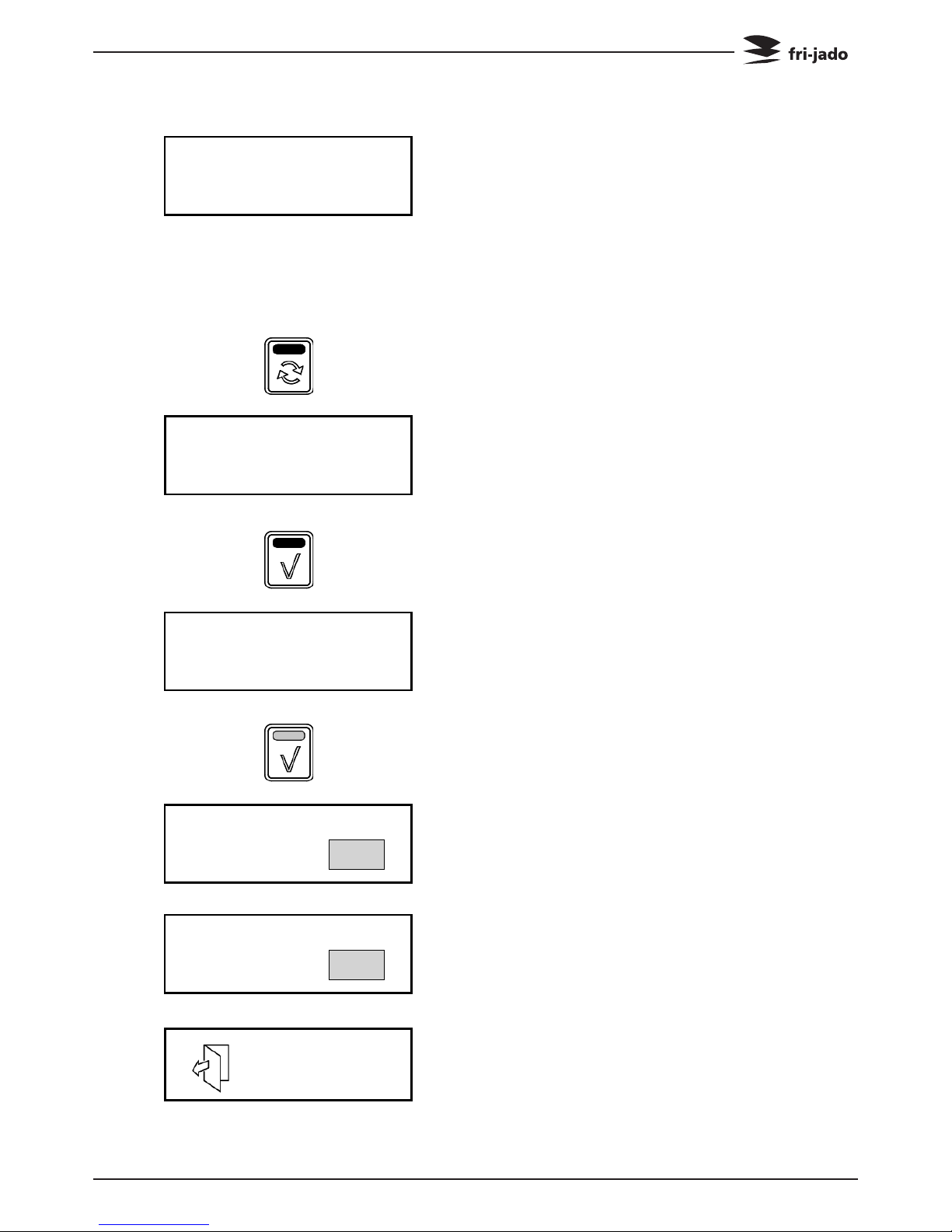
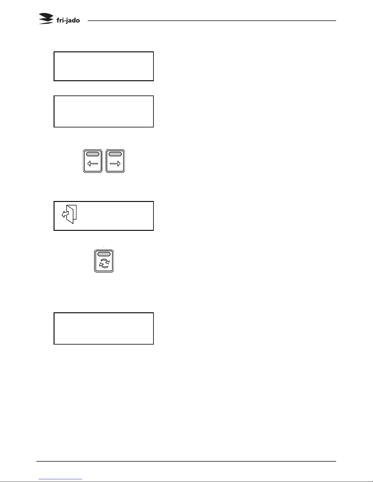
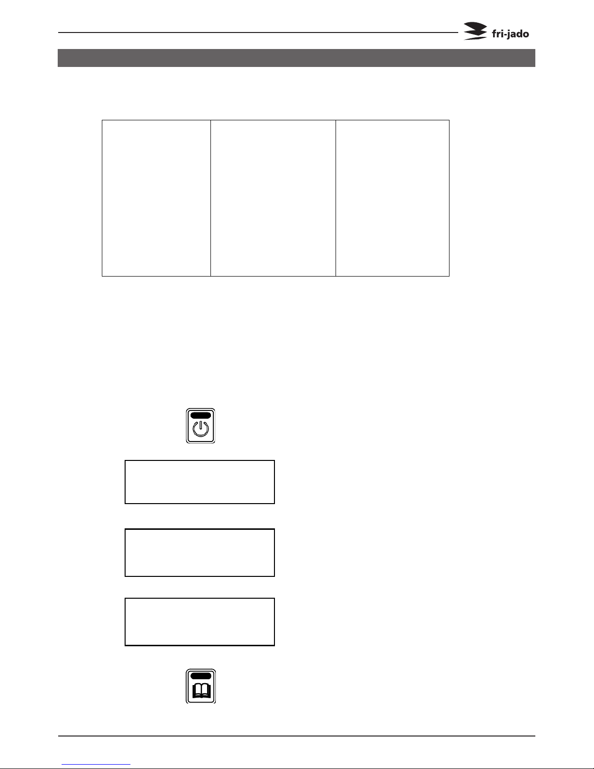
9. Pre-heat ready
(unit returns a sound signal).
Note: press OK or open the door to
stop the signal.
Display shows the next step of the
program.
Note: Screen 9 and 11 alternate
each 5 seconds.
10. When loading: press the rotor button
to turn the rotor.
11. After loading, close the door.
A reminder to empty the fat tray
appears.
12. Press OK to confirm.
13. Display show programmed
temperature and time (hour : min).
14. (Optional) Press OK button for
the actual temperature and time
(shows about 2 seconds).
15. During the last minute the time blinks.
16. Display show the remaining time, the
interval is 5 seconds.
17. Open the door.
Page 10
Service Manual TDR5/8 P TDW5/8 P form 9123911 rev. 10/2014
PROGRAMMING INSTRUCTIONS
TDR-P
eco
Models
Measure Core Temp.
2 Chicken
:00 Add time?
UNLOAD
Chicken
98 99 1 2 3
18. A reminder to measure the core
temperature appears.
Note: Screen 17 and 18 alternate
every 5 seconds.
19. (Optional, visible for 5 min. ) request
for additional time (minutes) after
opening the door.
Note: Add time is only available
when activated in the service menu.
20. (Optional) press right arrow for one
minute increase, press left arrow for
one minute decrease.
When activated program continues
at step 13.
21. Program ready, open door.
22. Press the rotor button to rotate the
rotor.
23. Close the door (if required clean the
unit).
24. Display shows the last operated
program.
Service Manual TDR5/8 P TDW5/8 P form 9123911 rev. 10/2014
Page 11
PROGRAMMING INSTRUCTIONS
OPERATION OPTIONS
TDR-P
eco
Models
Stop?
1 NO YES
Chicken
98 99 1 2 3
1 Chicken
230°C P123 10:05
1 Chicken
220°C P123 10:05
5.2. Operation options
5.2.1. To end a running program.
1. Press and hold start for 3 seconds.
2. Make a choice with the arrow
buttons.
Note: Select NO to abort ending the
program.
3. Confirm the selection.
(Within 5 seconds).
4. Display shows the last operated
program.
5.2.2. Check the actual temperature
1. For example: Check the current
temperature in
program 1 Chicken, step 1.
2. Press the OK button.
3. The display shows during 3 seconds
the actual temperature.
Page 12
Service Manual TDR5/8 P TDW5/8 P form 9123911 rev. 10/2014
PROGRAMMING INSTRUCTIONS
TDR-P
eco
Models
1 Chicken
230°C P123 10:05
1 Chicken
230°C P123 0:01
1 Chicken
230°C P123 0:05
1 Chicken
180°C P123 10:20
180°C 0:20
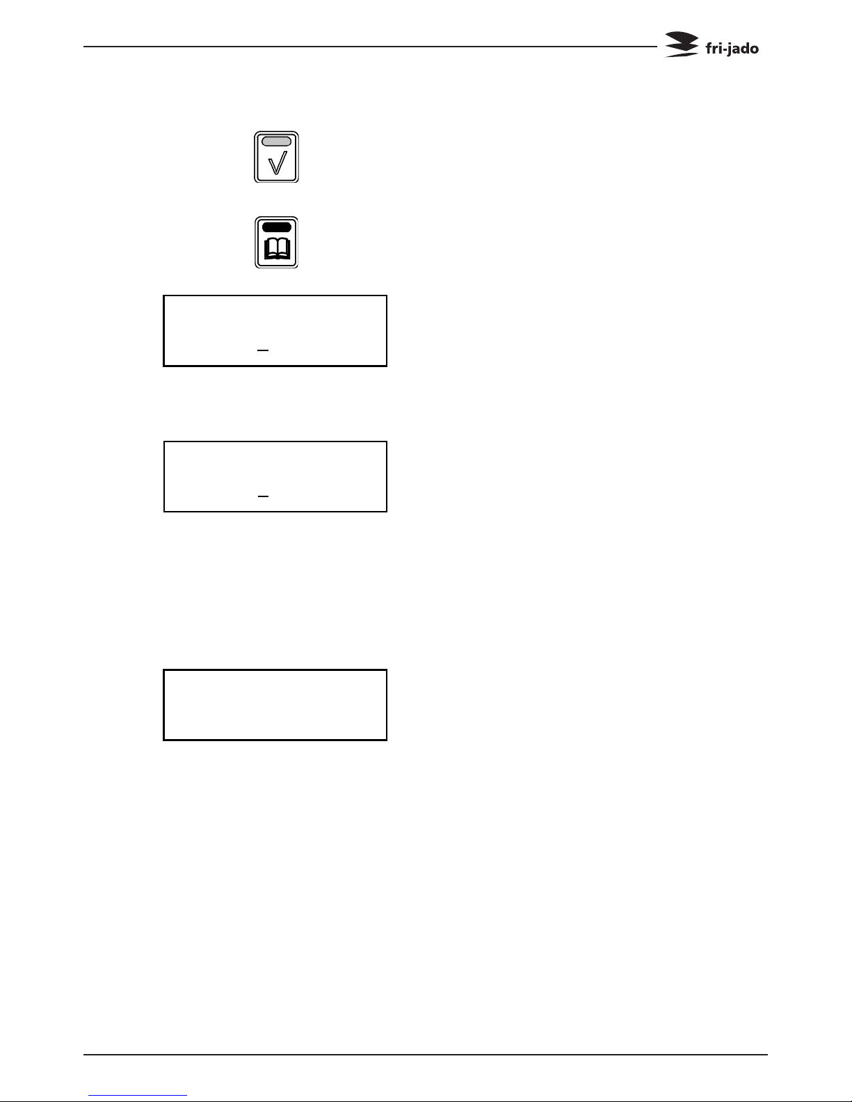
5.2.3. Check the remaining time in a program
1. Use the arrow buttons to show the
remaining time pro step.
2. Time left at step 1
(first digit blinks).
3. Time left at step 2
(second digit blinks).
5.2.4. Show all actual program information
1. Display shows actual program.
(step one is active).
2. Press List button.
3. Display shows the programmed
temperature and time.
4. Press List button again for additional
information.
P
180 0:07 3 230
0:05
0:05
1
180
0:20
0:20 H 085
0:10
0:10
2
210
0:10
0:10 C + 00:00:00
5. Display shows the programmed steps
and remaining times in one overview.
(Step – temperature – program time – actual time)
P: Preheat
1-3: Program step
H: Holding
C: Cook correction
Service Manual TDR5/8 P TDW5/8 P form 9123911 rev. 10/2014
Page 13
PROGRAMMING INSTRUCTIONS
TDR-P
eco
Models
1 Chicken
180°C P123 10:20
1 Chicken
ECO
180°C P123 10:20
180°C 0:20
6. Press the OK button to update the
screen
(automatically refreshed every 15
seconds).
7. Press List button to go back.
8. Display returns to the original
operating display.
5.2.5. Eco function
Optional: only available when activated
in the service menu.
In the ECO mode the accumulated heat
in the cavity will be used to cook the
product.
Depending on the settings, the product
and program an energy saving of 5% can
be achieved.
5.2.6. Cook correction
Optional: only available when activated
in the service menu.
Cook correction: Depending on the load
of products the cooking time will be
automatically adjusted.
The first cook is the reference cook and
will be used to fix the correct parameters.
The activation of the cook correction is
NOT visible in this display.
Page 14
Service Manual TDR5/8 P TDW5/8 P form 9123911 rev. 10/2014
PROGRAMMING INSTRUCTIONS
TDR-P
eco
Models
180°C 0:20
1 Chicken
180°C P123 10:20
1 Chicken
210°C P123 10:20
1 Chicken
230°C P123 10:20
1 Chicken
220°C P123 10:20
1 Chicken
220°C P123 0:15
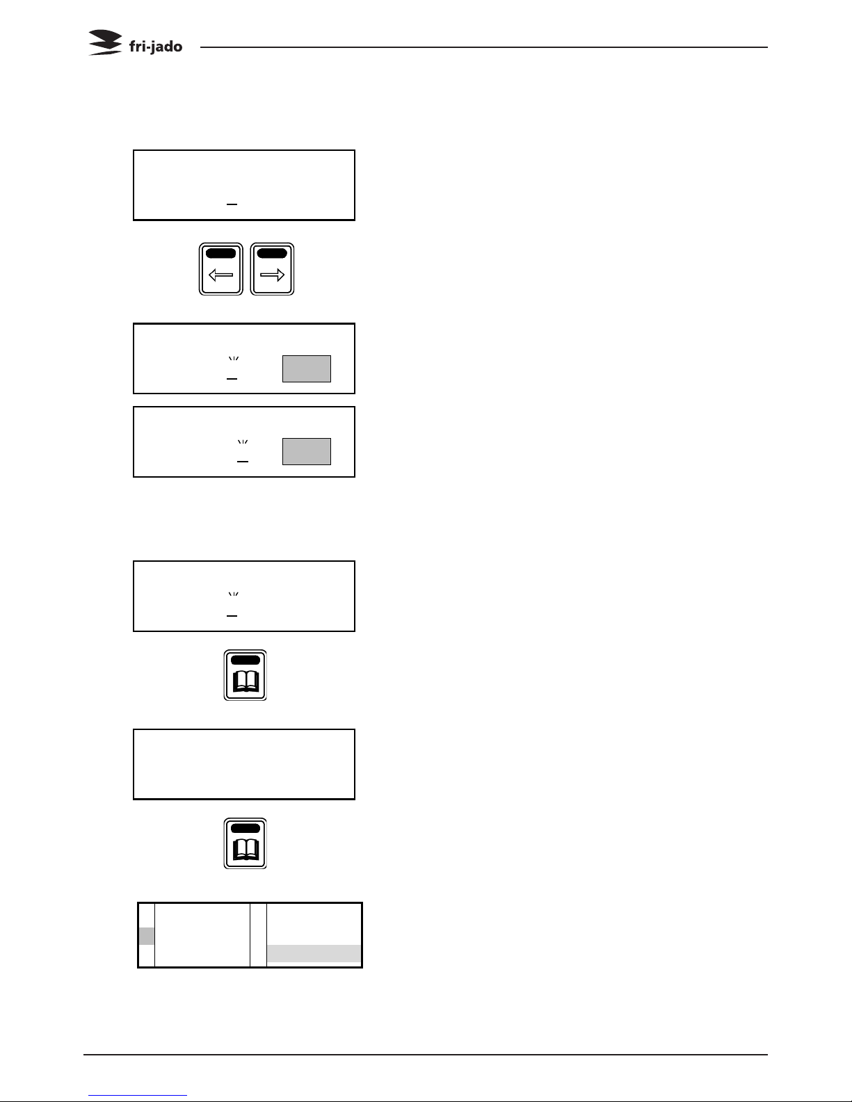
5.2.7. Display information
1. Display shows the programmed
temperature and time.
2. Press the list button.
3. Display shows after 3 seconds
cooking step + temperature + time.
Note: the current cooking step is
underlined.
4. Use arrow button for next screen.
5. Cooking step 1 is finished, sound
signal is returned.
Display shows next cooking step +
temperature + time.
6. Cooking step 2 is finished, sound
signal is returned.
Display shows next cooking step +
temperature + time.
7. Display shows the actual temperature
Note: the actual temperature blinks.
8. Display shows the remaining time.
Note: the remaining time blinks, after
5 seconds the original display is
shown again.
Service Manual TDR5/8 P TDW5/8 P form 9123911 rev. 10/2014
Page 15
PROGRAMMING INSTRUCTIONS
PROGRAMMING
TDR-P
eco
Models
Interface P Eco
TDR
Version x.x.x
Drumstick
6. MANAGER MEN U
6.1. Manager menu items
Programming
New
Edit
Delete
Copy
Parameters
Pre-Heat
Preheat temperature
Holding
Holding temperature
Cook correction*
Eco function*
Language
Big digits
Sound preheat
Sound step
Sound done
Change pin
Clock
Transfer
Version
USB
Reading recipes
Store recipes
* Only visible when selected in the service menu.
6.2. Programming the rotisserie
Possible programming steps:
- Preheat
- Step 1
- Step 2
- Step 3
- Holding
1. Start the unit.
2. Logo appears.
3. Unit information appears.
4. Last used program appears.
5. Press the list button.
Page 16
Service Manual TDR5/8 P TDW5/8 P form 9123911 rev. 10/2014
PROGRAMMING INSTRUCTIONS
TDR-P
eco
Models
Pin 0 - - -
Give User PIN code
Pin 1 - - -
Give User PIN code
Pin * 0 - -
Give User PIN code
MANAGER MENU
USB Programming 1Para.
RECIPES
NEW 1EDIT
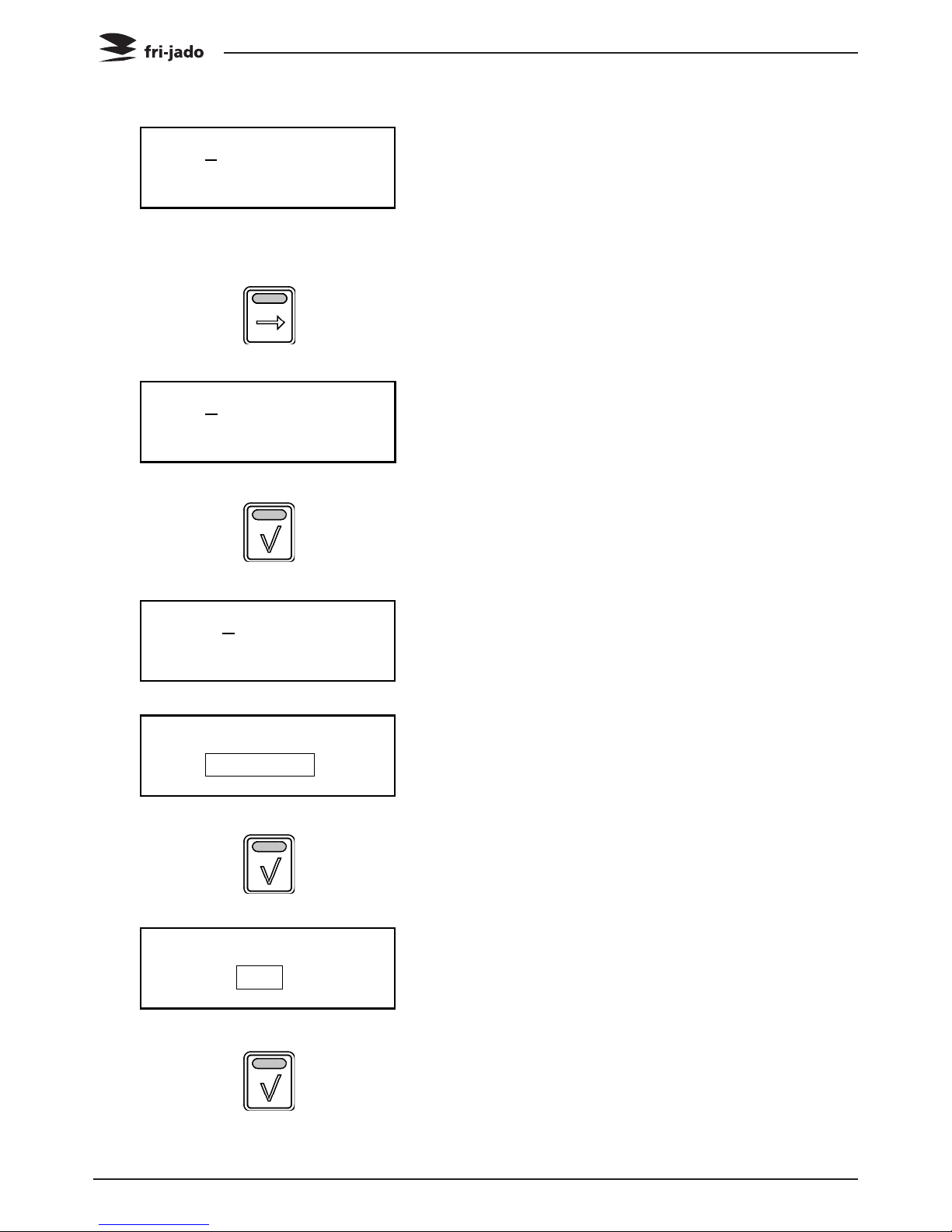
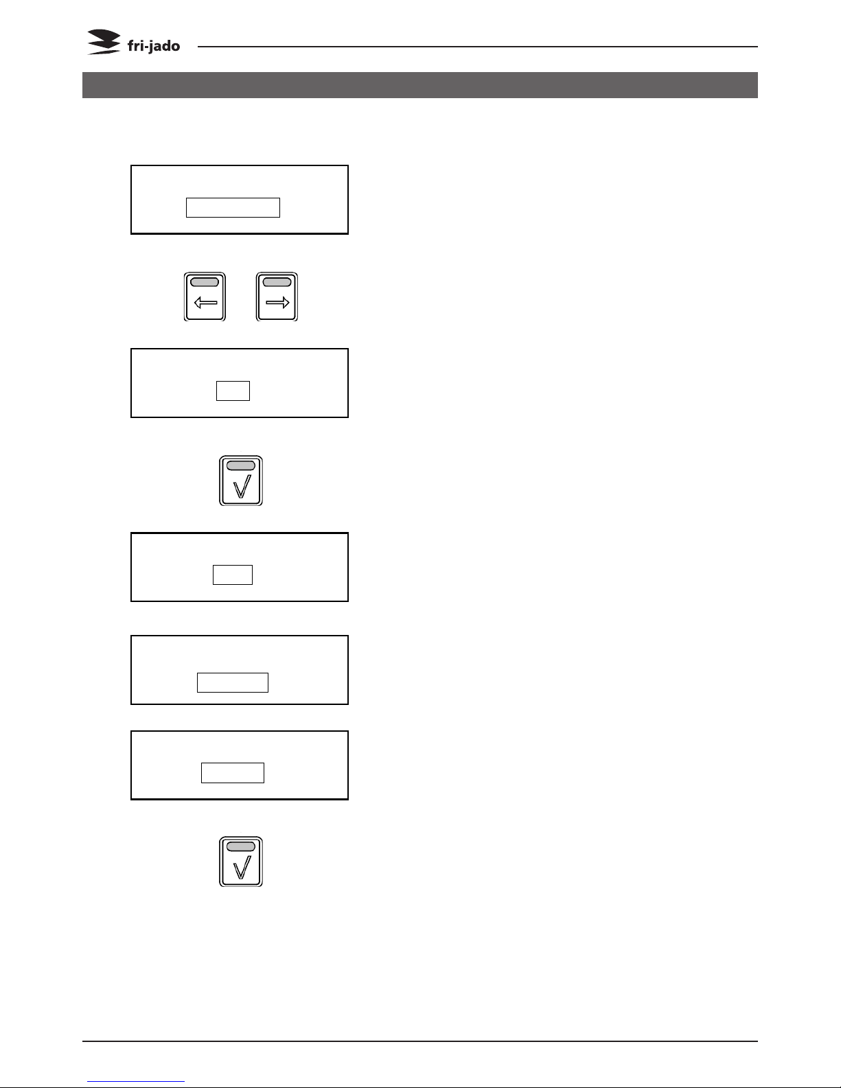
6. Enter the User PIN code.
Note: the original PIN code is 1111.
The operator can change the User
PIN code.
7. Use the arrow button to enter the PIN
code.
8. Press the arrow right button to
change the first digit.
9. Press the OK button to confirm.
10. The next digit is activated.
Change as required using the arrow
button.
Confirm with the OK button.
Repeat for the other digits.
11. Manager menu is activated.
Use the arrow buttons to toggle
between the sub menu’s.
12. Select “Programming” and Press the
OK button to co nfirm.
13. Use the arrow buttons to select a
new or existing recipe.
14. Press the OK button to confirm.
Service Manual TDR5/8 P TDW5/8 P form 9123911 rev. 10/2014
Page 17
PROGRAMMING INSTRUCTIONS
TDR-P
eco
Models
10
Choose new number
10 A--------------
ABC for others
10 TEST
10 TEST
Preheat Y Temp 210°C
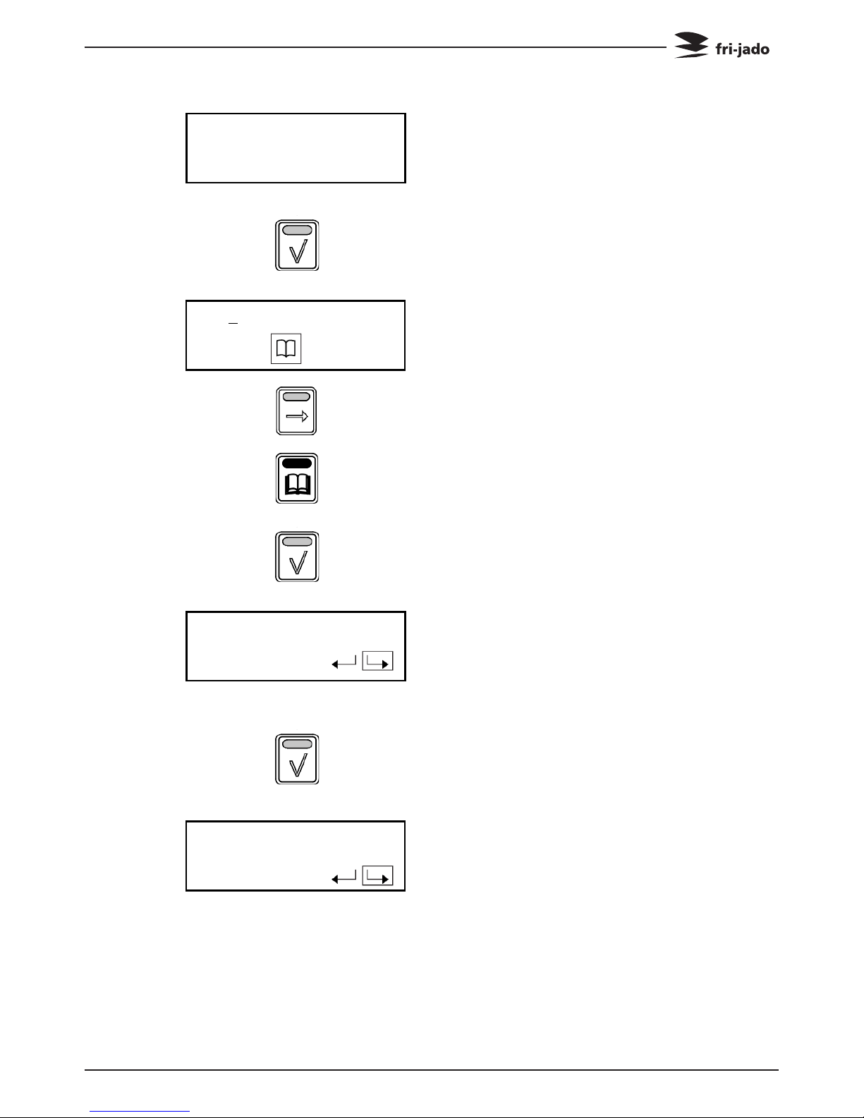
15. The first available number is shown.
Note: use the arrow right button to
select the next available number.
16. Press the OK button to confirm.
17. Enter the recipe name.
Use the arrow button to change the
character.
Note: ABC can be changed with the
use of the list button into lower /
higher case or special characters.
18. Press the OK button to confirm.
19. The new recipe name is shown
Note:
To change the name of the recipe
use the back arrow button and press
the OK button.
20. Press the OK button to confirm.
21. Set the preheat function and
temperature (default set on 210 °C /
425°F). Press the left arrow button
and the OK button to change the preheat setting.
Note: Pre-heat is only available when
activated in the parameter list.
Preheat functions:
Y: Yes
N: No
C: Continuously
Page 18
Service Manual TDR5/8 P TDW5/8 P form 9123911 rev. 10/2014
PROGRAMMING INSTRUCTIONS
TDR-P
eco
Models
10 Step 1
Temp 1 - - °C
10 Step 1
Temp 21 - °C
10 Step 1
Temp 215 °C
10 Step 1
Temp 215 °C Time 1 - -
22. Press the OK button to confirm.
23. Set the “step 1” temperature.
Starting with the first digit.
24. Use the arrow buttons to
increase/decrease the value of the
selected digit.
25. Press the OK button to confirm.
26. Set the second digit.
27. Press the OK button to confirm.
28. Set the third digit.
29. Press the OK button to confirm.
30. Set the “step 1” time.
Starting with the first digit.
Note:
Enter the time in minutes.
31. Use the arrow buttons to
increase/decrease the value of the
selected digit.

Service Manual TDR5/8 P TDW5/8 P form 9123911 rev. 10/2014
Page 19
PROGRAMMING INSTRUCTIONS
TDR-P
eco
Models
10 Step 1
Temp 215 °C Time 21 -
10 Step 1
Temp 215 °C Time 210
10 Step 1
Temp 215 °C Time 210
10 Step 2
Temp 215 °C
10 Holding
Temp 85 °C Time 999
32. Press the OK button to confirm.
33. Set the second digit.
34. Press the OK button to confirm.
35. Set the last digit.
36. Press the OK button to confirm.
37. The Step is now completed.
Select the right arrow and press the
OK button to go to the next step.
Select the left arrow button and press
the OK button to go back to the last
setting.
Select the and press the OK
button to finish programming.
38. Program the next step (when
required). See step 1 for the
procedure.
39. After step 3 or when entering no time
at step 2 (or 3) the holding step will
appear. Set the temperature and time
as required.
Note:
Set the time to 999 for continuous
operating.
Only available when activated (refer
to section 6.3).
Page 20
Service Manual TDR5/8 P TDW5/8 P form 9123911 rev. 10/2014
PROGRAMMING INSTRUCTIONS
TDR-P
eco
Models
10 TEST
Save 1Disc
RECIPES
NEW 1EDIT
MANAGER MENU
Usb Programming 1Para
Drumstick
5 6 7 8 9
40. When ready programming press the
OK button to co nfirm.
41. Save the finished programs.
Note: if the program is not saved all
changes are lost!
42. Press the OK button to confirm.
43. The screen returns to the RECIPES
menu.
44. Press back to enter the manager
menu.
45. Manager menu appears.
46. Press back to enter the user menu.
47. The last program used is shown.
Service Manual TDR5/8 P TDW5/8 P form 9123911 rev. 10/2014
Page 21
PROGRAMMING INSTRUCTIONS
MANAGER MENU: PARAMETERS
TDR-P
eco
Models
Pin * * * *
Give User PIN code
MANAGER MENU
Edit. Parameters 1Pin.
Language: Dutch
Cha. NEXT PAR. 1Prev.
Language: Dutch
Change Next
6.3. Programming parameters
1. Press the list button.
2. Enter your user PIN code.
3. Press the OK button to confirm.
4. Press the arrow buttons to select
Parameters.
5. Press the OK button to confirm.
6. Press the arrow buttons to select
Change or Previous.
Press the OK button to select the
next parameter.
7. To change the language, select
Change.
8. Press the OK button to change.
Page 22
Service Manual TDR5/8 P TDW5/8 P form 9123911 rev. 10/2014
PROGRAMMING INSTRUCTIONS
TDR-P
eco
Models
Language: English
Change Next 1Previous
Save parameters?
Save 1Disc.
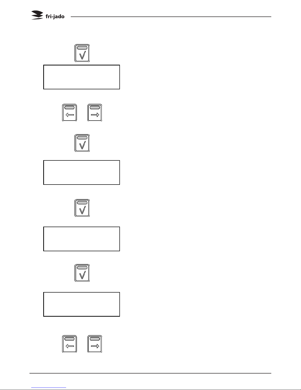
9. Use the arrow buttons to select
Change, Next or Previous.
Press back to enter the manager
menu.
10. Press the OK button to confirm or
select Discard to cancel.
11. Use the arrow buttons to select the
other settings:
Big Digits
YES/NO: Default set at YES
Sound preheat
Sound T1-T3 Default set at T1
Volume 1-4 Default set at 2
Sound Step
Sound T1-T3 Default set at T2
Volume 1-4 Default set at 1
Sound Done
Sound T1-T3 Default set at T3
Volume 1-4 Default set at 3
Preheat
YES/NO: Default set at NO
Preheat Temperature
50-250 °C (122-482 °F) Default set at 210°C (410°F)
Holding
YES/NO: Default set at YES
Holding Temperature
50-250 °C (122-482 °F) Default set at 85°C (185°F)
Cook correction
YES/NO: Default set at YES
Eco function
YES/NO: Default set at YES
Press back to enter the manager menu.
Press (again) back to enter the user menu.
10. Use the arrow buttons to select
Save and press the OK button to confirm.
This is valid for software version V1.04-09
or higher.
Note: when you select the Undo key the
changes will not be saved and you go
back to step 4.
10a. Untill software version V1.03.10 you
had to press the undo key to go to save.
Service Manual TDR5/8 P TDW5/8 P form 9123911 rev. 10/2014
Page 23
PROGRAMMING INSTRUCTIONS
MANAGER MENU: CHANGE PINCODE
TDR-P
eco
Models
MANAGER MENU
Para Change Pin 1Clock
MANAGER MENU
Pin Clock 1Copy
MANAGER MENU
Clock Transfer 1Vers.
Pin 0 0 0 0
Enter new code
2012 / 10 / 1 8:01 AM
SET TIME 112..
Insert stick and press
enter
Interface P Eco
TDR
Version x.x.x
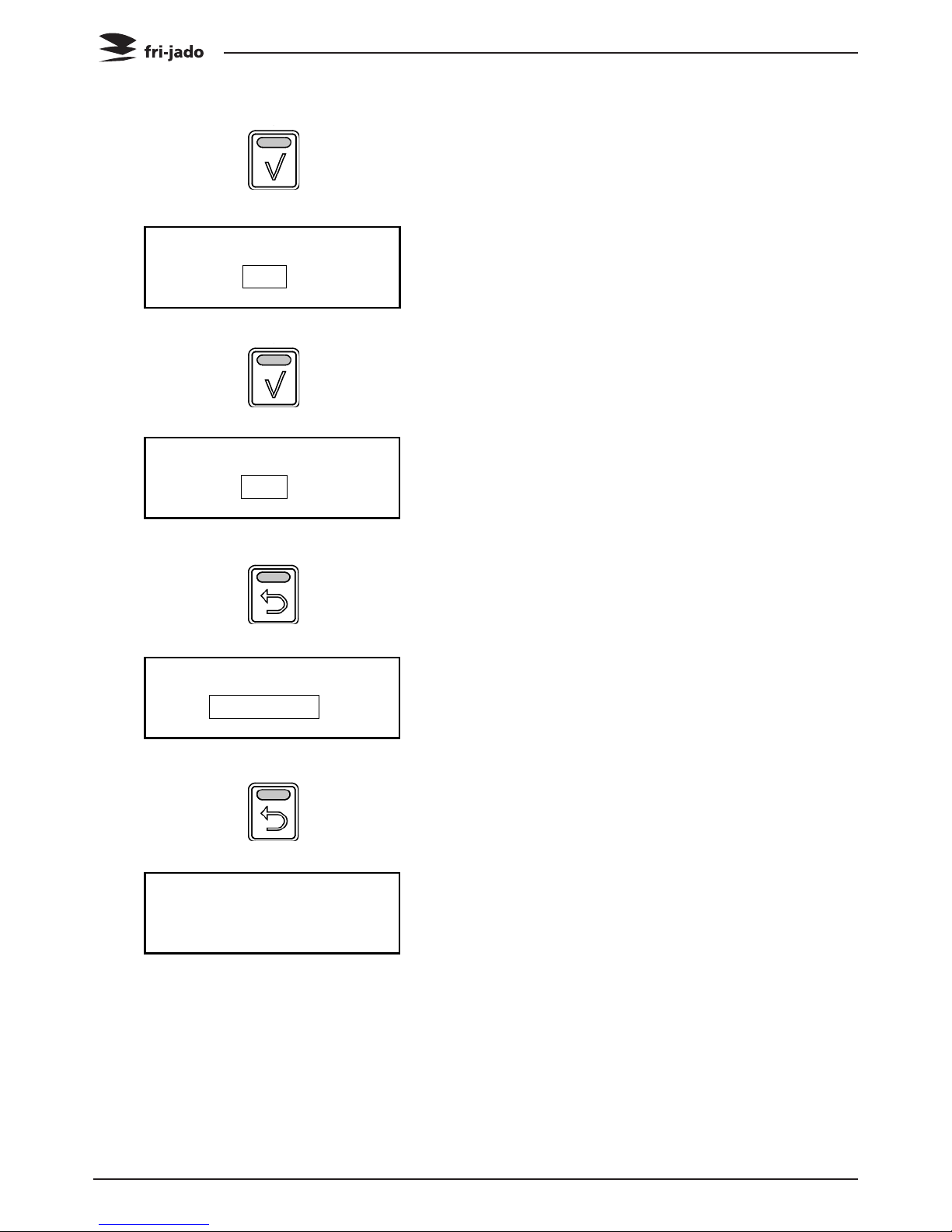
6.4. Change pin code
1. Manager menu.
2. Select Change Pin.
3. Press the OK button.
4. Enter the new pin code.
5. Press the OK button.
6.5. Clock
1. Manager menu.
2. Select Clock.
3. Press the OK button.
4. Set the correct date and time.
5. Press the OK button.
6.6. Transfer
1. Manager menu.
2. Select Transfer.
3. Press the OK button.
4. Insert stick and press OK.
6.7. Version
1. Display shows software version.
Page 24
Service Manual TDR5/8 P TDW5/8 P form 9123911 rev. 10/2014
PROGRAMMING INSTRUCTIONS
OPTIONS MANAGER MENU: USB
Note: When reading new programs all
existing programs will be deleted.
TDR-P
eco
Models
MANAGER MENU
USB Programming 1Para.
MANAGER MENU
USB Edit
USB
Read Sto.
A_ _ _ _ _ _ _ _
Save File Name
A
Save File Name
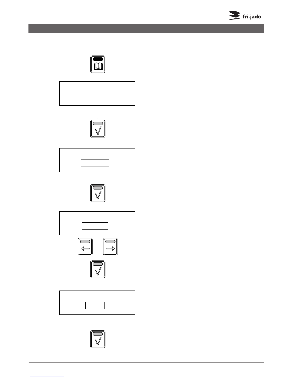
6.8. USB
1. Manager menu.
2. Use the arrow buttons to select the
USB function.
3. Screen shows the USB function.
Place the USB stick into the USBslot.
4. Press the OK button to confirm.
5. Use the arrow buttons to select Read
to exchange an existing program or
STORE to save a program.
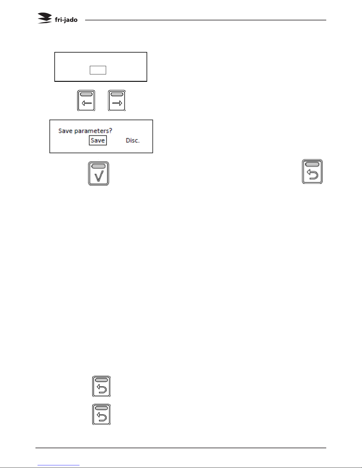
Option STORE:
6. Enter the file name by using the
arrow buttons and OK button.
7. Select Save.
8. Press the OK button to confirm.
Service Manual TDR5/8 P TDW5/8 P form 9123911 rev. 10/2014
Page 25
PROGRAMMING INSTRUCTIONS
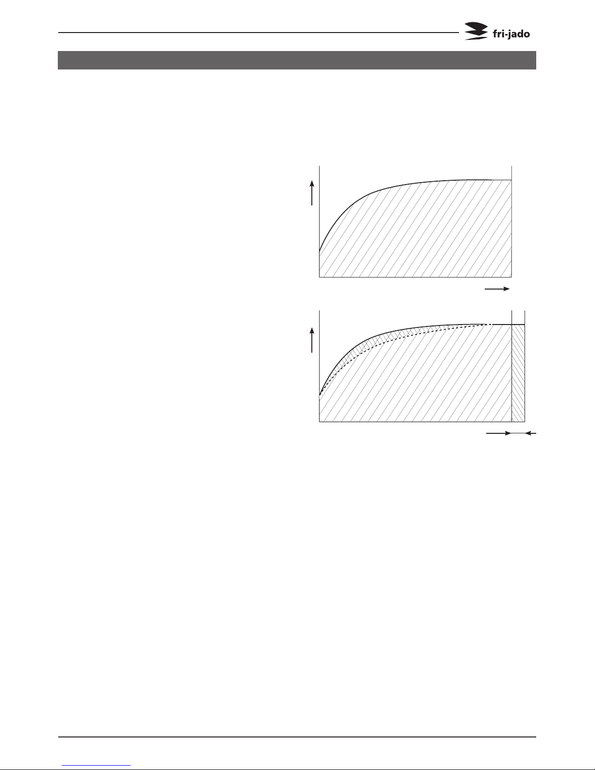
°C
°C
Extra time
Cooking time
Temparature curve
with half load
The program calculates the surface from the
diagram below the curved line. (temperature
* time). The result is the so called heat num
ber. This heat number is stored into the cook
ing program.
All further cooking programs will try to get
the same heat number.
The second diagram shows an example with
full load. It takes more time for the unit to
reach the programmed cooking temperature.
See dashed line. The surface above the dashed
line represents the missing part of the heat
number. The cook correction will put this miss
ing part behind the normal cooking time.
Therefore extra time is added in order to
reach the desired heat number.
It is also possible that time is deducted in case
a smaller load has been put into the oven.
Time will be added in case of:
A bigger load.
A colder load. (straight from the freezer).
A lower mains voltage.
Somebody opened the door.
Time will be deducted in case of:
A smaller load.
A warmer load. (defrosted)
A higher mains voltage.
Note 1:
In case the time or temperature will be
changed in the cooking program, the heat
number will be adapted with this amount.
Note 2: Only if you delete a program or
change the name the “learning”process starts
again from the beginning.
The automatic cook correction facility will automaticly add or deduct time to the pro
grammed cooking time in order to have constant cooking quality.
After programming a new program, the first cooking process will be the “learning” process.
It is recommended to do the first cook with a half load.
THE AUTOMATIC COOK CORRECTION
The heat number is stored in the cooking
program. In case such a program is copied
and stored in another rotisserie, the heat
number goes with it.
It is possible that in case the program has
changed a lot, the cook correction is not
able to perform well anymore. In that case
the program has to be deleted and repro
grammed with the good parameters.
It is possible to disable this cook cor
rection feature in the service parameters.
See “parameter listings” -> “cook correction”.

Page 26
Service Manual TDR5/8 P TDW5/8 P form 9123911 rev. 10/2014
REMOVAL AND REPLACEMENT OF PARTS
WARNING: Disconnect the electrical power to the machine
at the main circuit box. Place a tag on the circuit box indicating the circuit is being serviced.
1. Remove the cross head screws that secure
the panel to the frame.
2. Remove the panel.
3. Reverse the procedure to install.
1. Remove the right side panel according
prior procedure.
2. Remove the screws securing both large
and small top covers.
3. Remove the top cover. (Lift at right side
and remove to the left).
4. Reverse the procedure to install.
1. Remove the right side panel according prior
procedures
2. Remove the bolt, nut and ring on the top
side on the backside of the operating panel.
3. Pull the panel away from the top side.
4. Remove the flatcables and earth cable from
the CPU board on the backside.
5. Remove the panel.
6. Reverse the procedure to install.
REMOVAL AND REPLACEMENT OF PARTS FOR THE TDR 5 AND TDR 8
RIGHT OR LEFT SIDE PANEL
TOP COVER
OPERATING PANEL (GENERAL)

Page 27
Service Manual TDR5/8 P TDW5/8 P form 9123911 rev. 10/2014
REMOVAL AND REPLACEMENT OF PARTS
1. Remove the right side panel according
prior procedure.
2. Disconnect the wiring.
3. Remove on the inside bottom of the electric panel the bolt and nuts.
4. Slide the electric panel upwards to remove
this.
5. Reverse the procedure to install.
1. Remove the right hand panel according
prior procedure.
2. Remove the operating panel according
prior procedure.
3. Remove the 4 nuts and rings on the CPU
board and remove the board.
4. Replace the USB connection from old to
new operating panel.
5. Reverse the procedure to install.
Note 1: For connection flatcable of the keypads
see CPU board on page 28.
Note 2: For older units with earth wire in right
hand bottom corner. Take care that the ring
terminal doesn’t make contact with with the
solder point (see arrow) .Otherwise the illumination of the display and keys can be out.
ELECTRIC PANEL
OPERATING PANEL, GLASS + BACKPLATE + KEYPAD
REPLACING A LAMP

1. Remove the right side panel according
prior procedure.
2. Disconnect the wiring and flatcable on the
board.
3. Remove the board from the clips by pressing the clips together.
4. Reverse the procedure to install.
Page 28
Service Manual TDR5/8 P TDW5/8 P form 9123911 rev. 10/2014
REMOVAL AND REPLACEMENT OF PARTS
Before changing the CPU board and display be
sure to download (with a USB stick) or write
down the grilling programs and the parame
ters.
1. Remove the right side panel according
prior procedure.
2. Remove the operating panel according
prior procedure.
3. Remove the 4 nuts and rings on the CPU
board and remove the board.
4. Reverse the procedure to install.
5. Read the grilling programs and parameters
from the USB stick to the CPU board.
Note 1: Flatcable keypad must be connected
to connector “Touchpanel 1” on CPU board.
Note 2: “Touchpanel 2” is flatcable connection
for the rotor switch keypad on customer side.
Note 3: For older units with earth wire in
right hand bottom corner. Take care that the
ring terminal doesn’t make contact with with
the solder point (see arrow) .Otherwise the illumination of the display and keys can be out.
CPU BOARD
POWER AND I/O BOARD

Page 29
Service Manual TDR5/8 P TDW5/8 P form 9123911 rev. 10/2014
REMOVAL AND REPLACEMENT OF PARTS
1. Remove the right side panel, the operating
panel and the CPU board according prior
procedures.
2. Remove the keypad and degrease the
surface of the glass.
3. Glue the new keypad on its place with the
red colored connectors on the bottom side.
4. Reverse the procedure to install.
Note 1: For connection flatcable of the
keypads see CPU board on page 28.
Note 2: When the keypad is on the panel on
customer side you need a long extended
flatcable for connection to the CPU board.
KEYPAD
REPLACING OF BROKEN BUZZER
1. Remove the right side panel according
prior procedure.
2. Remove the operating panel according
prior procedure.
3. Stick connector of new buzzer in plug next
to the existing broken buzzer (see white
arrow).
4. Reverse the procedure to install.
Note: buzzer can dangle loosely without any
problem.

Page 30
Service Manual TDR5/8 P TDW5/8 P form 9123911 rev. 10/2014
REMOVAL AND REPLACEMENT OF PARTS
Caution: Do not touch the glass with your
hands. The moisture from your hands could
affect the live span of the lamp. This moisture can be removed with alcohol while the
lamp is cold.
Note: Use a clean rag or paper towel to replace the lamp.
1. Remove the bolts that secure the protection guard of the Halogen lamp and
remove the guard.
2. Push the lamp to either side and pull it
down to remove the lamp.
3. Remove the top cover according prior
procedure.
4. Disconnect the wiring on the terminal
block.
5. Remove the insulation above the light
fixture.
6. Remove the screws that secure the lamp
holder and remove the holder from the
inside.
7. Reverse the procedure to install.
Note 1: Be sure that the “drop”on the lamp
is pointing downwards.
Note 2: Check the lamp reflecting shield and
replace this if corroded.
INFRA-RED HALOGEN LAMP HOLDER
 Loading...