

Fri-Jado TDRac Service Manual
WWW.FRIJADO.COM
Service Manual TDRac
PKII
form 9120931 rev. 11/2017
- NOTICE -
This manual is prepared for the use of trained Service Technicians and should not be used by
those not properly qualied. If you have attended a training for this product, you may be
qualied to perform all the procedures in this manual.
This manual is not intended to be all encompassing. If you have not attended a training for
this product, you should read, in its entirety, the repair procedure you wish to perform to
determine if you have the necessary tools, instruments and skills required to perform the
procedure. Procedures for which you do not have the necessary tools, instruments and
skills should be performed by a trained technician.
Reproduction or other use of this Manual, without the express written consent of Fri-Jado, is
prohibited.
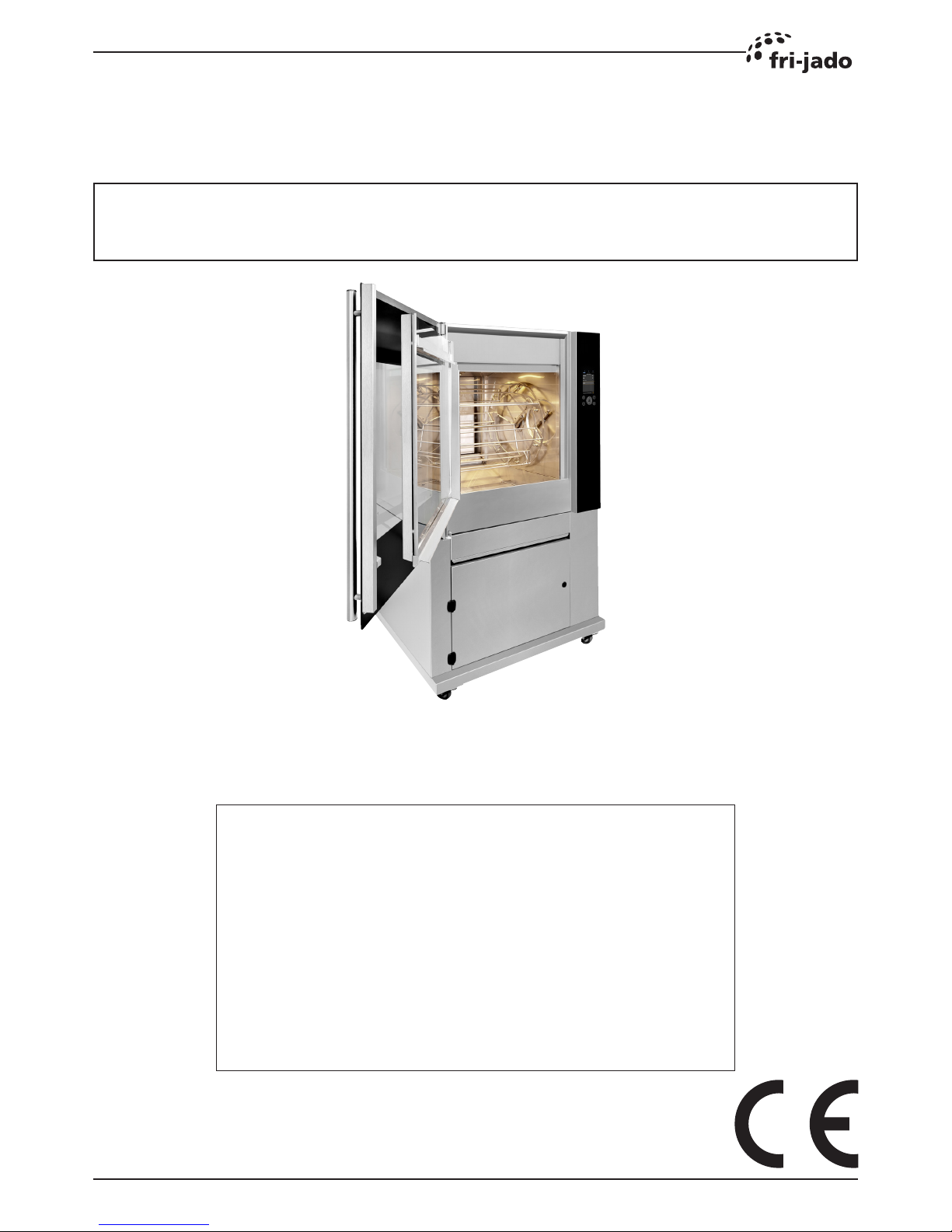
SERVICE MANUAL
TDRac

Page 2
Service Manual TDRac
PKII
form 9120931 rev. 11/2017
TABLE OF CONTENTS
EMPTY PAGE

Page 3
Service Manual TDRac
PKII
form 9120931 rev. 11/2017
TABLE OF CONTENTS
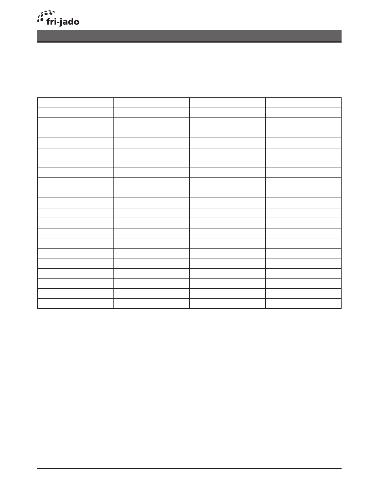
Versions
Version Issue date
dd/mm/yy
Remarks
1711 28/11/2017 First release

INDEX
Page 4
Service Manual TDRac
PKII
form 9120931 rev. 11/2017
TABLE OF CONTENTS
Index ........................................................................................................................................................... 4
TDR-ac Installation ..................................................................................................................................... 6
TDRac, technical data ............................................................................................................................. 6
Introduction ............................................................................................................................................. 8
Unpacking the unit .................................................................................................................................. 8
Location ................................................................................................................................................... 9
Electrical supply ...................................................................................................................................... 9
Factory
default ! ............................................................................................................................................. 9
European models .................................................................................................................................... 9
Factory
default ! ............................................................................................................................................. 9
American models .................................................................................................................................... 9
Legs / Castors ....................................................................................................................................... 10
Tethering of the unit............................................................................................................................... 10
Power, Water and Drain connections .....................................................................................................11
Water Requirements ..............................................................................................................................11
Connecting the drain tube ..................................................................................................................... 12
Extraction of the rotisserie ..................................................................................................................... 12
grease Collection .................................................................................................................................. 13
Test run ................................................................................................................................................. 13
Instructions for operators ...................................................................................................................... 13
TDR ac on Stand ................................................................................................................................... 14
TDR ac Hood ........................................................................................................................................ 15
Software ................................................................................................................................................... 16
Default parameters Version 6.01.00 TDRac (mark III) ................................................................... 16
Exploded views and partslists .................................................................................................................. 18
TDRac, Electrical parts ......................................................................................................................... 18
TDRac, Partslist Electrical parts ............................................................................................................ 19
TDRac, Doors ....................................................................................................................................... 20
TDRac, Partslist Doors .......................................................................................................................... 21
TDRac, Rotor ........................................................................................................................................ 22
TDRac, Partslist Rotor .......................................................................................................................... 23
TDRac, Blower & Heating ..................................................................................................................... 24
TDRac, Partslist Blower & Heating ....................................................................................................... 25
TDRac, Cleaning system ...................................................................................................................... 26
TDRac, Partslist Cleaning system ......................................................................................................... 27
TDRac, Sheet metal .............................................................................................................................. 28
TDRac, Partslist Sheet metal ................................................................................................................ 29
TDRac, Underframe .............................................................................................................................. 30
TDRac, Partslist Underframe ................................................................................................................ 31
Electrical diagrams .................................................................................................................................. 32
Circuit diagram TDRac (mark III) .......................................................................................................... 32
Wiring diagram TDRac (mark III) .......................................................................................................... 33
Circuit diagram TDRac (mark II) ........................................................................................................... 34
Wiring diagram TDRac (mark II) ........................................................................................................... 35
Circuit diagram TDRac (mark 1) ........................................................................................................... 36
Wiring diagram TDRac (mark 1) ........................................................................................................... 37

Page 5
Service Manual TDRac
PKII
form 9120931 rev. 11/2017
TABLE OF CONTENTS
EMPTY PAGE
Page 6
Service Manual TDRac
PKII
form 9120931 rev. 11/2017
TDRAC, TECHNICAL DATA
TDR-AC INSTALLATION
Dimensions Width mm 1045
Depth mm 975
Height mm 1795
Weight Gross kg 300
Net kg 250
Maximum ambient tem-
perature
°C 35
Sound pressure dB (A) < 70
Electrical installation Voltage V 3N ~ 400/230
Frequency Hz 50/60
Required power kW 10.5
Max. nominal current A 16
Plug CEE-form A 16
Length m approx. 2.2
Water connection Aerated inch ¾
Water pressure kPa 200 – 500
Acidity pH 7.0 - 8.0
Chlorides ppm <30
Hardness ¹ dH <4
Drain Open connection mm min. 40
European models
Consult the identication plate to get the proper specications of the unit. The electrical data may vary from
country to country.
¹ See chapter “water requirements” for detailed information

TDR-ac Installation
Page 7
Service Manual TDRac
PKII
form 9120931 rev. 11/2017
Dimensions approx. Width inch 41
Depth inch 38½
Height inch 70½
Weight Gross lbs 662
Net lbs 552
Maximum ambient tem-
perature
°F 95
Sound pressure dB (A) < 70
Electrical installation Voltage V 3 ~ 208
Frequency Hz 50/60
Required power kW 12
Max. nominal current A 35.5
Plug NEMA 15 - 50P
Length inch 75
Water connection Aerated inch ¾
Water pressure kPa 200 – 500
Acidity pH 7.0 - 8.0
Chlorides ppm <30
Hardness ¹ dH <4
Drain Open connection inch min. 1 5⁄8
American models
¹ See chapter “water requirements” for detailed information

TDR-ac Installation
Page 8
Service Manual TDRac
PKII
form 9120931 rev. 11/2017
INTRODUCTION
• Unpacking of the unit.
• Remove the pallet under the unit with the help of a fork lift.
• Put the unit on his location.
• Check if there is enough free space around the unit (see installation drawing).
• Check the electrical supply.
• Tethering of the unit.
• Connect the water.
• Connect drain.
• Grease collection.
• Make a test run on 250 °C.
• Give instructions to the operator.
UNPACKING THE UNIT
Immediately after unpacking the oven, check for possible shipping damage. If the oven is found to
be damaged, save the packaging material and contact the carrier.
The standard way to remove the oven from a pallet is with a fork lift.
910 mm
36”
TDR-ac Installation
Page 9
Service Manual TDRac
PKII
form 9120931 rev. 11/2017
Prior to installation, test the electrical service to assure that it agrees with the specications on the
machine data plate located on the right side panel near the controls. The connecting cable for the
unit must be equipped with an approved plug connection. If use is to be made of a permanent con-
nection, the connecting cable must be connected to a manual on/o switch that is installed near
the unit in a clear visible manner.
ELECTRICAL SUPPLY
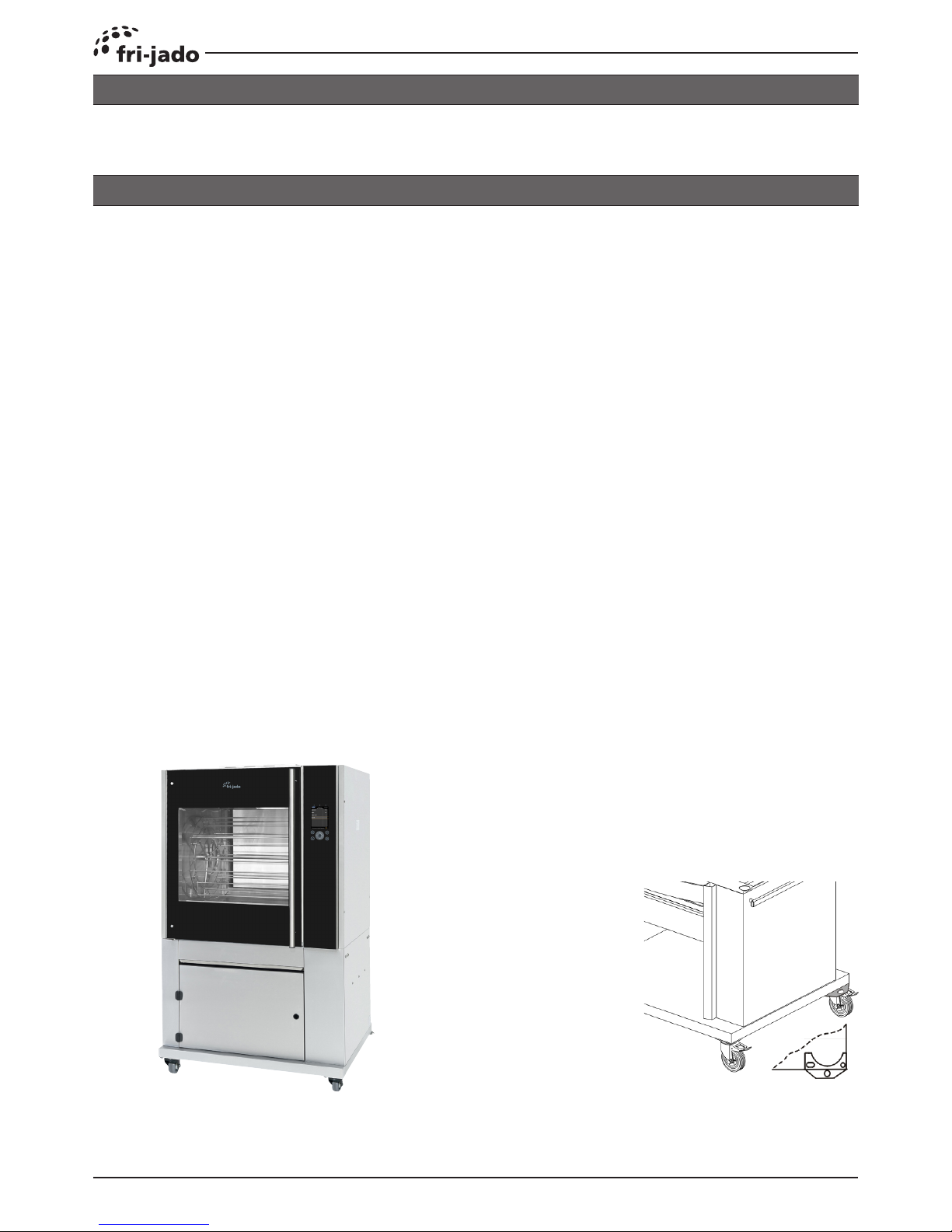
IMPORTANT: Make sure you lea-
ve sucient space around the rotisserie to easily remove or insert
the rotor. If the base has (rotating)
wheels, the oor on which it rests
must be level.
LOCATION
The oven must be installed on a level surface. The installation location must allow adequate clea-
rances for servicing and proper operation.
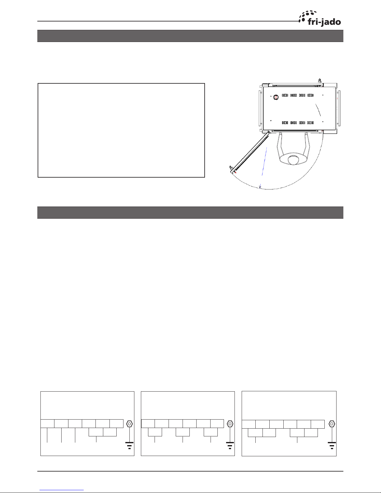
The unit must be connected according to one of the the gures below.
1 2 3 4 5 6
N
L1
1 2 3 4 5 6
L2L1 L3 N
1 2 3 4 5 6
L2L1 L3
400 V, 3N ~ 50...60 Hz
200 V - 230 V, 1N ~ 50...60 Hz
200 V - 230 V, 3 ~ 50...60 Hz
FACTORY
DEFAULT !
EUROPEAN MODELS
FACTORY
DEFAULT !
AMERICAN MODELS
TDR-ac Installation
Page 10
Service Manual TDRac
PKII
form 9120931 rev. 11/2017
The TDR ac is placed on a stand with 2 swivel and 2 locking swivel castors.
LEGS / CASTORS
TETHERING OF THE UNIT
Warning: Safety standards require that, when this appliance is properly connected to the electrical
power supply using exible conduit, adequate means be provided to limit movement of the ap-
pliance without depending on or transmitting stress to the electrical conduit. This means that, as
part of the installation, the base or bottom unit of stacked models must be secured to the building
structure (typically either wall or oor) to limit the movement of the appliance and, thus, helping to
prevent damage to the conduit during cleaning, maintenance and service operations.
A tether bracket, as shown on the drawing below, is provided with the stand. Based on the routing
of the exible conduit, the bracket must be installed along with the caster to one corner of the base
using the hardware provided. The remaining open hole in the center of the tether bracket is to
be used to secure one end of the tether (locally supplied chain, cable, etc.). The other end of the
tether is to be secured to an anchoring point in the building structure.
Note: Length of tether must be shorter than the exible conduit to make sure that during appliance
movement, no stress is transmitted to the conduit.

TDR-ac Installation
Page 11
Service Manual TDRac
PKII
form 9120931 rev. 11/2017
Drain hose, Ø 27 x Ø 20, L= 1,2 mtr
(Ø 1 1/16 x Ø 13/16”, L= 47”)
See chapter “connecting the drain tube” for
further information.
Water supply hose
G 3/4”, L= 1,1 mtr (43”)
400 V European models
Power connection
Cee form 16 A,
L= 2,5 mtr (98”)
200-230 V USA models
Power connection
NEMA 15-50
WATER REQUIREMENTS
The supplied tap water must have the following conditions:
1. Minimum pressure 200 kPa (2 bar)
2. Maximum pressure 500k Pa (5 bar)
3. Maximum water temperature 55 °C (130 °F)
4. Acidity pH 7.0 - 8.0
5. Chlorides less than 30 ppm
6. Use a sediment pre-lter or a strainer for the reduction of silica and other non-dissolved sedi-
ments.
Water hardness and descaling lters.
7. A descaling lter is advised when the hardness of the water is > 4° dH (4 Grains/Gal).
8. A descaling lter is mandatory when the hardness of the water is > 20° dH (20 Grains/Gal).
Note that the cleaning capacity of the cleaning tablets will decrease with harder water.
The by-pass of the descaling lter, if applicable, needs to be adjusted to zero.
Refer to the lters manual to determine the lter capacity. This lter capacity needs to be adjusted
in the manager parameters.
POWER, WATER AND DRAIN CONNECTIONS
The Power, water and drain connections can be found on the back of the unit.
√ X
√
X
X
TDR-ac Installation
Page 12
Service Manual TDRac
PKII
form 9120931 rev. 11/2017
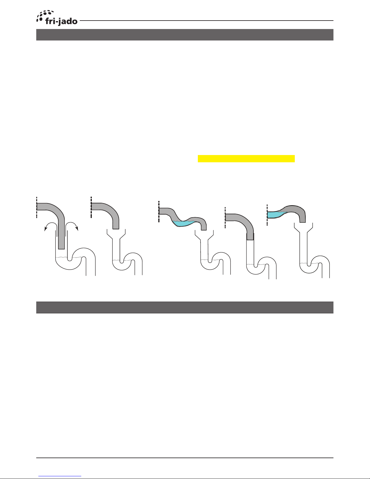
CONNECTING THE DRAIN TUBE
An open draining system with a 110 mm (4 1/2”) funnel is recommended. The drain tube has an
outside diameter of 33 mm (1 1/3”).
• It is not allowed to make a closed connection!
• Make sure that the tube is not kinked and is sloping downwards to the drain funnel.
• The minimum inside diameter of the sewer pipe needs to be 40 mm (1 1/2”).
• A siphon in the customers sewer is highly recommended to prevent odors from coming out of
the sewer.
• See below examples.
An extraction hood is prescribed when the unit is NOT delivered with the special Fri-Jado extrac-
tion hood mounted on it.
The TDR produces about 10 m³ (350 cf) vapour during a cooking cycle. When placing the rotisse-
rie under an extraction hood, the following guide lines have to be considered:
• The minimum capacity of the extraction hood has to be 800 m³/h (25000 cf/h).
• The extraction hood has to extend minimum by 20 cm (8”) on all sides of the rotisserie.
• The extraction hood has to have a free hight, above the rotisserie, of a minimum of 30 cm (12”).
• The rotisserie has to be accessible for service purposes.
• The extraction hood has to have facilities to drain any condensation, down to a drain.
EXTRACTION OF THE ROTISSERIE
Possible lay outs of drain
Faulty lay outs of drain
 Loading...