

Fri-Jado TDR auto-clean Series, TDR5s auto clean, TDR8i auto clean, TDR8s auto clean, TDR8+8s auto clean Service Manual
SERVICE MANUAL
TDR auto-clean
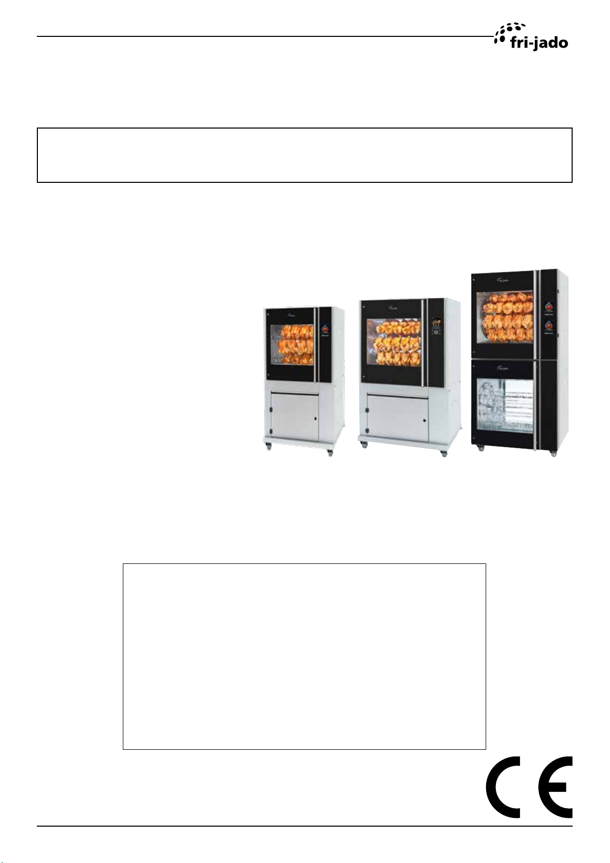
MODELS
TDR5s auto clean
TDR8i auto clean
TDR8s auto clean
TDR8+8s auto clean
TDR5s ac TDR8i ac TDR8+8s ac
WWW.FRIJADO.COM
- NOTICE -
This manual is prepared for the use of trained Service Technicians and should not be used by
those not properly qualied. If you have attended a training for this product, you may be
qualied to perform all the procedures in this manual.
This manual is not intended to be all encompassing. If you have not attended a training for
this product, you should read, in its entirety, the repair procedure you wish to perform to
determine if you have the necessary tools, instruments and skills required to perform the
procedure. Procedures for which you do not have the necessary tools, instruments and
skills should be performed by a trained technician.
Reproduction or other use of this Manual, without the express written consent of Fri-Jado, is
prohibited.
Service Manual TDRac
PKII form 9120931 rev.10/2019

TABLE OF CONTENTS
EMPTY PAGE
Page 2
Service Manual TDRacPKII form 9120931 rev.10/2019
TABLE OF CONTENTS
Versions
Version Issue date
Remarks
dd/mm/yy
1711 28/11/2017 First release
1803 07/03/2018 general update
1810 19/10/2018 Unpack instructions changed and minor changes in exploded views
1905 28/05/2019 Extended with TDR8+8 ac dimension drawing and electrical diagram +
minor corrections in parts lists
1908 30/08/2019 Extended with TDR5 ac
INDEX
Index .......................................................................................................................................................... 3
TDR-ac Installation ................................................................................................................................... 5
TDRac, technical data ............................................................................................................................. 5
Introduction ............................................................................................................................................. 7
Unpacking the unit .................................................................................................................................. 7
Location ................................................................................................................................................... 9
Electrical supply ...................................................................................................................................... 9
Legs / Castors ....................................................................................................................................... 10
Tethering of the unit............................................................................................................................... 10
Power, Water and Drain connections TDR5 ac and TDR8 ac ...............................................................11
Power, Water and Drain connections TDR8+8 ac .................................................................................11
Water Requirements ............................................................................................................................. 12
Connecting the drain tube ..................................................................................................................... 13
Extraction of the rotisserie ..................................................................................................................... 13
grease Collection .................................................................................................................................. 14
Test run ................................................................................................................................................. 14
Instructions for operators ...................................................................................................................... 14
TDR 5 ac ............................................................................................................................................. 15
TDR 8 ac on Stand ................................................................................................................................ 16
TDR 8 ac with Hood ............................................................................................................................. 17
TDR 8+8 ac ........................................................................................................................................... 18
TDR 8 ac on counter ............................................................................................................................ 19
Software .................................................................................................................................................. 20
MEnu settings TDRac ....................................................................................................................... 20
Cleaning program TDRac ................................................................................................................. 21
MEnu settings TDRac ....................................................................................................................... 22
Service Manual TDRacPKII form 9120931 rev. 10/2019
Page 3

TABLE OF CONTENTS
First Settings and Diagnostic Tools TDR ac .................................................................................. 23
I/O test TDRac (i-control) ................................................................................................................... 24
Updating software TDRac (i-control) .................................................................................................. 26
Updating software TDRac (S-control) ................................................................................................ 27
Default parameters Version 10004 TDR8s-ac 208 Volt ................................................................... 28
Default parameters Version 10004 TDR8s-ac ................................................................................ 30
Default parameters Version 10004 TDR5s-ac ................................................................................. 32
Default parameters Version 6.01.25 TDR8i-ac .................................................................................... 34
Cleaning Process TDRac .................................................................................................................. 36
Cleaning Process TDRac (3 steps) (
Exploded views and partslists .............................................................................................................. 38
TDRac, Electrical parts ......................................................................................................................... 38
TDRac, Partslist Electrical parts ............................................................................................................ 39
TDRac, Electrical parts ......................................................................................................................... 40
TDRac, Partslist Electrical parts ............................................................................................................ 41
TDRac, Control panels .......................................................................................................................... 42
TDRac, Partslist Control panels ............................................................................................................ 43
TDRac, Doors ....................................................................................................................................... 44
TDRac, Partslist Doors .......................................................................................................................... 45
TDRac, Lighting and sensors ................................................................................................................ 46
TDRac, Lighting and Sensors ............................................................................................................... 47
TDRac, Rotor ........................................................................................................................................ 48
TDRac, Partslist Rotor .......................................................................................................................... 49
TDRac, Blower & Heating ..................................................................................................................... 50
TDRac, Partslist Blower & Heating ....................................................................................................... 51
TDRac, Cleaning system ...................................................................................................................... 52
TDRac, Partslist Cleaning system ......................................................................................................... 53
TDRac, Cleaning system, untill ser nr 100087797 ................................................................................ 54
TDRac, Partslist Cleaning system, untill ser nr 100087797 ................................................................. 55
TDRac, Sheet metal .............................................................................................................................. 56
TDRac, Partslist Sheet metal ................................................................................................................ 57
TDR8 ac, Underframe ........................................................................................................................... 58
TDR8 ac, Partslist Underframe ............................................................................................................. 59
TDRac, Stacking parts .......................................................................................................................... 60
TDRac, Stacking parts .......................................................................................................................... 61
TDR5 ac, Underframe ........................................................................................................................... 62
TDR5 ac, Partslist Underframe ............................................................................................................. 63
Fasteners .............................................................................................................................................. 64
Electrical diagrams ................................................................................................................................ 66
Circuit diagram TDRac .......................................................................................................................... 66
Wiring diagram TDRac .......................................................................................................................... 67
parameter “cleaning cycles) .............................................................. 37
Page 4
Service Manual TDRacPKII form 9120931 rev.10/2019
TDR-AC INSTALLATION
TDRAC, TECHNICAL DATA
Consult the identication plate to get the proper specications of the unit. The electrical data may vary from
country to country.
European models
Model TDR 5-AC TDR 8-AC TDR 8+8-AC
Dimensions Width mm 885 1050 1050
Depth mm 760 915 915
Height mm 1735 1795 2135
Weight Gross kg 250 300 480
Net kg 180 250 430
Maximum ambient
temperature
Sound pressure dB (A) < 70 < 70 < 70
Electrical installation Voltage V 3N ~ 400/230 3N ~ 400/230 3N ~ 400/230
Frequency Hz 50/60 50/60 50/60
Required power kW 6,6 10.5 21
Max. nominal
current
Plug CEE-form A 16 16 32
Length m approx. 2.2 approx. 2.2 approx. 2.2
Water connection Aerated inch ¾ ¾ ¾
Water pressure kPa 200 – 500 200 – 500 200 – 500
Acidity pH 7.0 - 8.0 7.0 - 8.0 7.0 - 8.0
Chlorides ppm <30 <30 <30
Hardness ¹ dH <4 <4 <4
Drain Open connection mm min. ID
°C 35 35 35
A 10 16 31
min. ID
min. ID
40mm /
1 1/2”
¹ See chapter “water requirements” for detailed information
Service Manual TDRacPKII form 9120931 rev. 10/2019
40mm /
1 1/2”
40mm /
1 1/2”
Page 5
TDR-ac Installation
American models
Models TDR 7-AC TDR 7+7-AC
Dimensions approx. Width inch 41 41
Depth inch 38½ 38½
Height inch 70½ 84
Weight Gross lbs 662 1059
Net lbs 552 948
Maximum ambient
temperature
Sound pressure dB (A) < 70 < 70
Electrical installation Voltage V 3 ~ 208 3 ~ 208
Frequency Hz 50/60 50/60
Required power kW 12 12 (2x)
Max. nominal
current
Plug NEMA 15 - 50P 15 - 50P (2x)
Length inch 75 75 (2x)
Water connection Aerated inch ¾ ¾ (2x)
Water pressure kPa 200 – 500 200 – 500
Acidity pH 7.0 - 8.0 7.0 - 8.0
Chlorides ppm <30 <30
Hardness ¹ dH <4 <4
°F 95 95
A 35.5 35,4 (2x)
Drain Open connec-
tion
¹ See chapter “water requirements” for detailed information
inch min. 1 5⁄8 min. 1 5⁄8 (2x)
Page 6
Service Manual TDRacPKII form 9120931 rev.10/2019
TDR-ac Installation
INTRODUCTION
• Unpacking of the unit.
• Remove the pallet under the unit with the help of a fork lift.
• Put the unit on his location.
• Check if there is enough free space around the unit (see installation drawing).
• Check the electrical supply.
• Tethering of the unit.
• Connect the water.
• Connect drain.
• Grease collection.
• Make a test run on 220 °C.
• Give instructions to the operator.
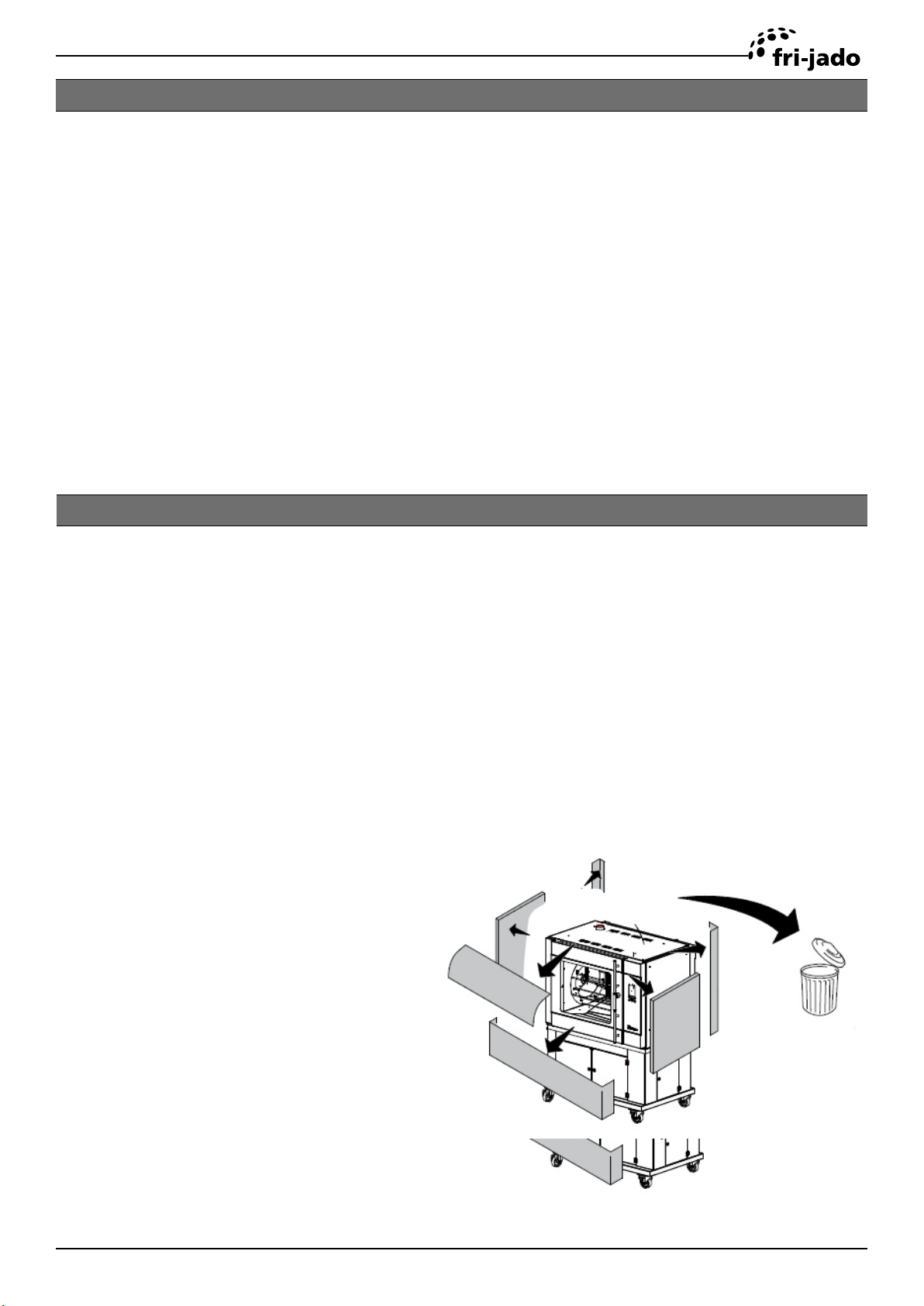
UNPACKING THE UNIT
Immediately after unpacking the oven, check for possible shipping damage. If the oven is found to
be damaged, save the packaging material and contact the carrier.
The standard way to remove the oven from a pallet is with a fork lift.
The alternative way is explained on the next page.
Do this with at least 2 people.
Dispose the packagaging according local legislation..
Service Manual TDRacPKII form 9120931 rev. 10/2019
Page 7
TDR-ac Installation
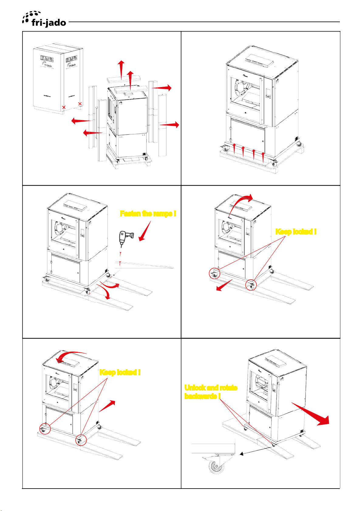
2
Cut straps, remove box and tempex.
Fasten the ramps !
Place the ramps in front of the pallet
and fasten them.
Remove screws (front 4x and back 4x)
Keep locked !
Tilt the unit slightly and remove the front beam.
Keep locked !
Tilt the unit the other way and remove
the beam at the back..
Page 8
Unlock and rotate
backwards !
Carefully roll the unit onto the oor.
Service Manual TDRacPKII form 9120931 rev.10/2019
TDR-ac Installation
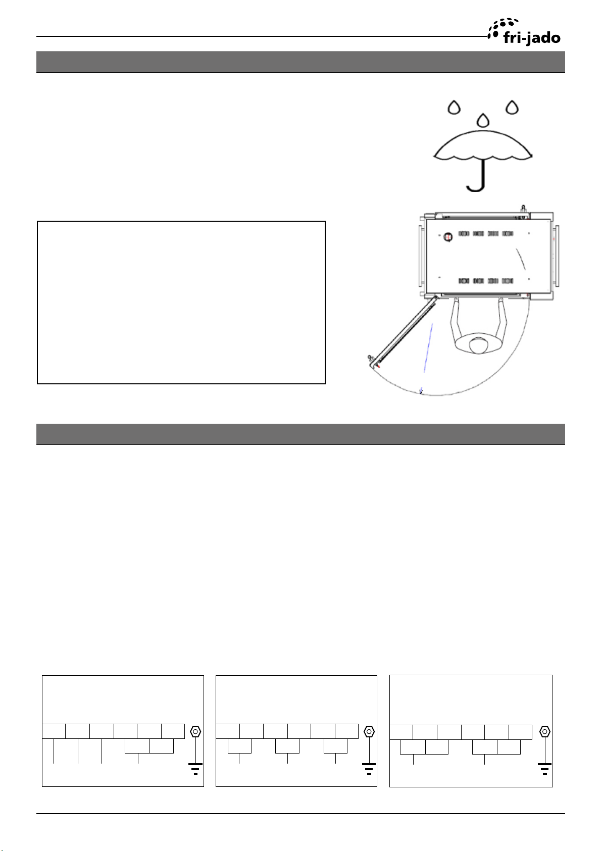
LOCATION
The oven must be installed on a level surface. The
installation location must allow adequate clearances
for servicing and proper operation.
The oven must be protected against falling moisture !
IMPORTANT: Make sure you leave sucient space around the rotisserie to easily remove or insert
the rotor. If the base has (rotating)
wheels, the oor on which it rests
must be level.
910 mm
36”
ELECTRICAL SUPPLY
Prior to installation, test the electrical service to assure that it agrees with the specications on the
machine data plate located on the right side panel near the controls. The connecting cable for the
unit must be equipped with an approved plug connection. If use is to be made of a permanent con-
nection, the connecting cable must be connected to a manual on/o switch that is installed near
the unit in a clear visible manner.
The unit must be connected according to one of the the gures below.
Factory default !
European models
400 V, 3N ~ 50...60 Hz
1 2 3 4 5 6
L3 N
L2L1
Service Manual TDRacPKII form 9120931 rev. 10/2019
200 V - 230 V, 3 ~ 50...60 Hz
Factory default !
American models
1 2 3 4 5 6
L2L1
L3
200 V - 230 V, 1N ~ 50...60 Hz
1 2 3 4 5 6
L1
N
Page 9
TDR-ac Installation
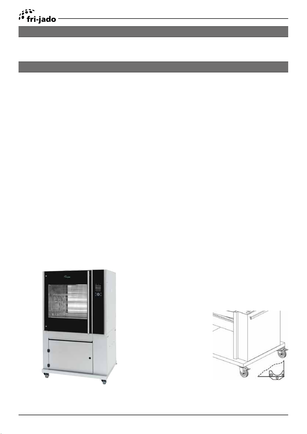
LEGS / CASTORS
The TDR ac is placed on a stand with 2 swivel and 2 locking swivel castors.
TETHERING OF THE UNIT
Warning: Safety standards require that, when this appliance is properly connected to the electrical
power supply using exible conduit, adequate means be provided to limit movement of the ap-
pliance without depending on or transmitting stress to the electrical conduit. This means that, as
part of the installation, the base or bottom unit of stacked models must be secured to the building
structure (typically either wall or oor) to limit the movement of the appliance and, thus, helping to
prevent damage to the conduit during cleaning, maintenance and service operations.
A tether bracket, as shown on the drawing below, is provided with the stand. Based on the routing
of the exible conduit, the bracket must be installed along with the caster to one corner of the base
using the hardware provided. The remaining open hole in the center of the tether bracket is to
be used to secure one end of the tether (locally supplied chain, cable, etc.). The other end of the
tether is to be secured to an anchoring point in the building structure.
Note: Length of tether must be shorter than the exible conduit to make sure that during appliance
movement, no stress is transmitted to the conduit.
Page 10
Service Manual TDRacPKII form 9120931 rev.10/2019
TDR-ac Installation
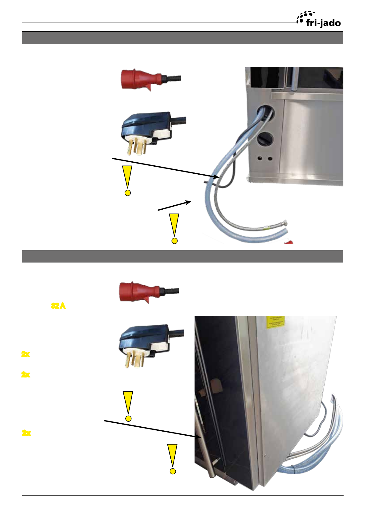
POWER, WATER AND DRAIN CONNECTIONS TDR5 AC AND TDR8 AC
The Power, water and drain connections can be found on the back of the unit.
400 V European models
Power connection
Cee form 16 A,
L= 2,5 mtr (98”)
200-230 V USA models
Power connection
NEMA 15-50
Water supply hose
G 3/4”, L= 1,1 mtr (43”)
Flush the tap before connecting
Drain hose, Ø 33 x Ø 25, L= 1,2 mtr
(Ø 1 5/16 x Ø 1”, L= 47”)
See chapter “connecting the drain tube” for
further information.
POWER, WATER AND DRAIN CONNECTIONS TDR8+8 AC
The Power, water and drain connections can be found at the side of the unit.
400 V European models
Power connection
Cee form
L= 2,5 mtr (98”)
200-230 V USA models
Power connection
2x NEMA 15-50
2x Water supply hose
32 A,
G 3/4”, L= 1,1 mtr (43”)
Flush the tap before connecting
2x Drain hose, Ø 33 x Ø 25, L= 1,2 mtr
(Ø 1 5/16 x Ø 1”, L= 47”)
See chapter “connecting the drain tube” for
further information.
Service Manual TDRacPKII form 9120931 rev. 10/2019
Page 11

TDR-ac Installation
WATER REQUIREMENTS
The supplied tap water must have the following conditions:
1. Minimum pressure 200 kPa (2 bar)
2. Maximum pressure 500 kPa (5 bar)
3. Maximum water temperature 55 °C (130 °F)
4. Acidity pH 7.0 - 8.0
5. Chlorides less than 30 ppm
6. Use a sediment pre-lter or a strainer for the reduction of silica and other non-dissolved sedi-
ments.
Water hardness and descaling lters.
7. A descaling lter is advised when the hardness of the water is > 4° dH (4 Grains/Gal).
8. A descaling lter is mandatory when the hardness of the water is > 20° dH (20 Grains/Gal).
Note that the cleaning capacity of the cleaning tablets will decrease with harder water.
The by-pass of the descaling lter, if applicable, needs to be adjusted to zero.
Refer to the lters manual to determine the lter capacity. This lter capacity needs to be adjusted
in the manager parameters.
Page 12
Service Manual TDRacPKII form 9120931 rev.10/2019
TDR-ac Installation
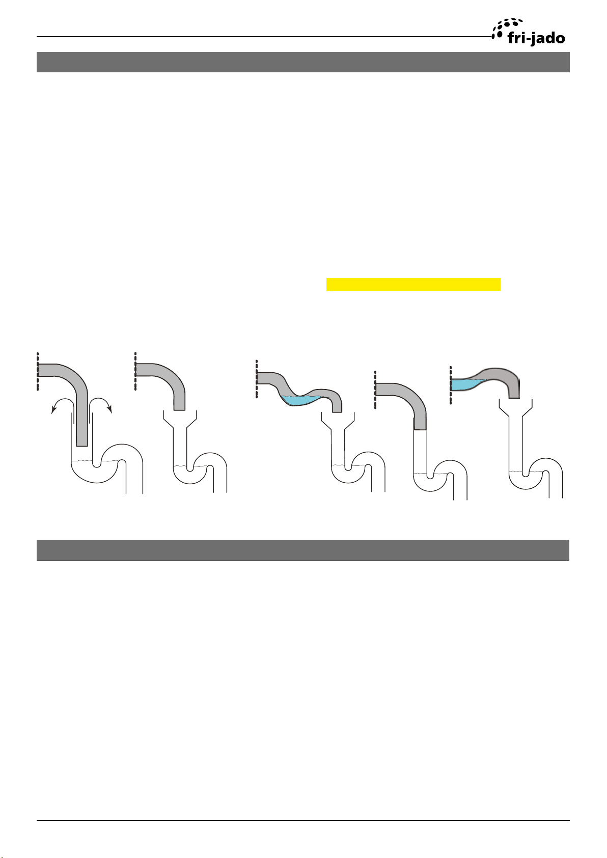
CONNECTING THE DRAIN TUBE
An open draining system with a 110 mm (4 1/2”) funnel is recommended. The drain tube has an
outside diameter of 33 mm (1 5/16”).
• It is not allowed to make a closed connection!
• Make sure that the tube is not kinked and is sloping downwards to the drain funnel.
• The minimum inside diameter of the sewer pipe needs to be 40 mm (1 1/2”).
• A siphon in the customers sewer is highly recommended to prevent odors from coming out of
the sewer.
• See below examples.
Possible lay outs of drain
√ X
An extraction hood is prescribed when the unit is NOT delivered with the special Fri-Jado Exhaust
√
EXTRACTION OF THE ROTISSERIE
Faulty lay outs of drain
X
X
Hood mounted on it.
The TDR5 produces about 6 m³ (210 cf) and TDR8 produces about 10 m³ (350 cf) vapour during a
cooking cycle. When placing the rotisserie under an extraction hood, the following guide lines have
to be considered:
• The minimum capacity of the extraction hood has to be 480 / 800 m³/h (15000 / 25000 cf/h).
• The extraction hood has to extend minimum by 20 cm (8”) on all sides of the rotisserie.
• The extraction hood has to have a free hight, above the rotisserie, of a minimum of 30 cm (12”).
• The rotisserie has to be accessible for service purposes.
• The extraction hood has to have facilities to drain any condensation, down to a drain.
Service Manual TDRacPKII form 9120931 rev. 10/2019
Page 13
TDR-ac Installation
GREASE COLLECTION
For TDR5-ac and TDR8-ac:
Place the bucket, which is delivered with the unit, inside the stand under the drain pipe.
It is also possible to put other containers in the underframe to collect the grease.
Note 1: In one run, 5 liters (1.3 gallon) grease can come out.
Note 2: The temperature of the grease can go up to 80 °C (176 °F).
Make sure that the container meets the above requirements.
For TDR8+8-ac:
The stacked unit comes with a grease tray underneath.
The grease from both units will be collected in this tray.
TEST RUN
The oven must be burned in to release any odours that might result from heating the new oven
surfaces. Operate the oven at maximum temperature setting of 220 °C for 30 minutes. Smoke with
an unpleasant odour will normally be given o during this burn-in period.
INSTRUCTIONS FOR OPERATORS
After installation of the rotisserie the operator of the unit has to be instructed.
The instruction has to cover the following subjects:
• Programming and options.
• Working of the unit.
• Free space of unit for cooling of drive motor and blowers.
• Run through the user manual.
• How to run the cleaning program and placing cleaning tablets.
• Cleaning of the tablet dispenser and bottom lters after the cleaning program has nished.
• Periodical maintenance:
o Cleaning of fan plate every 3 months.
o Yearly maintenance by service agent.
• How to react for information or service calls.
Page 14
Service Manual TDRacPKII form 9120931 rev.10/2019
TDR-ac Installation
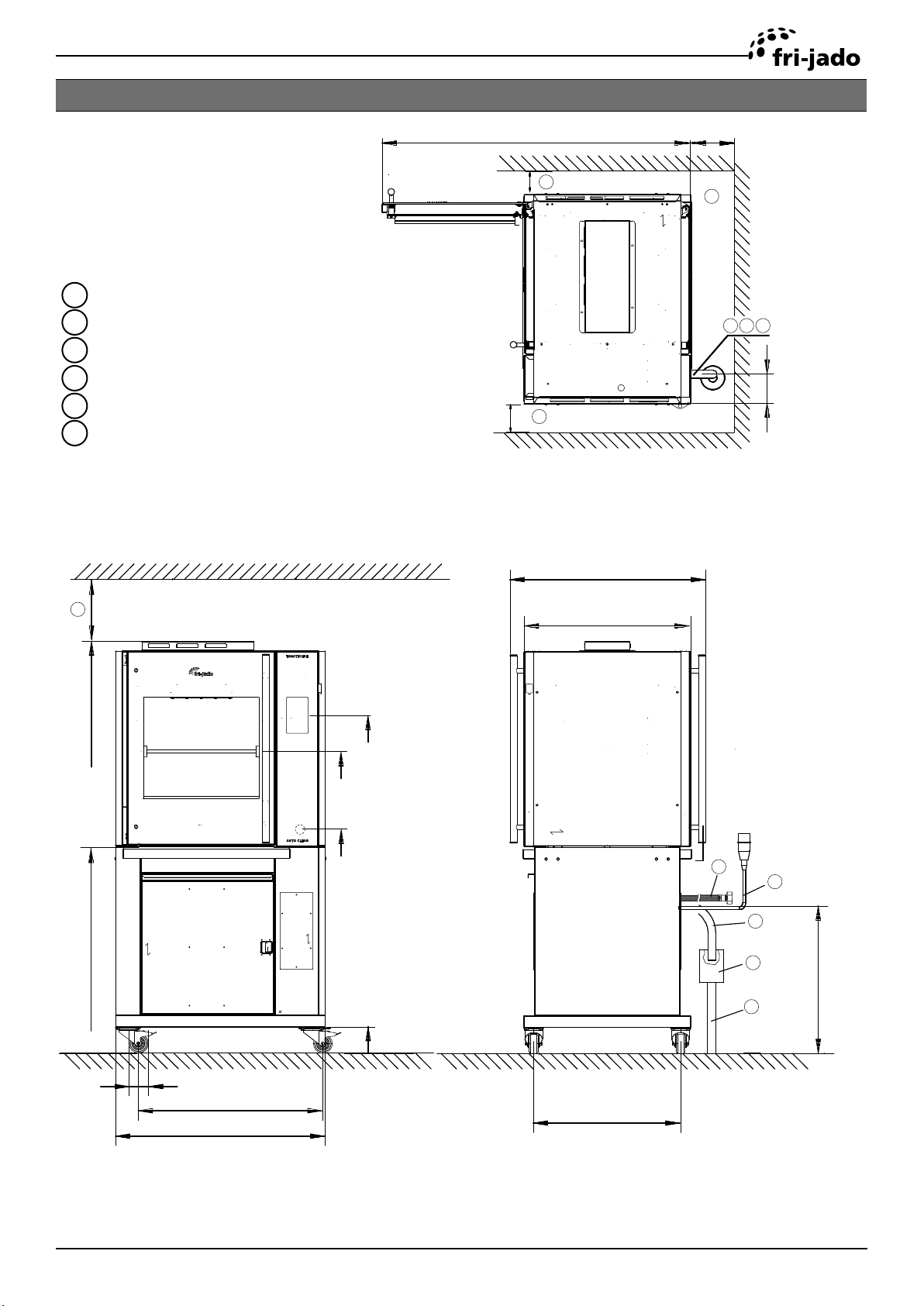
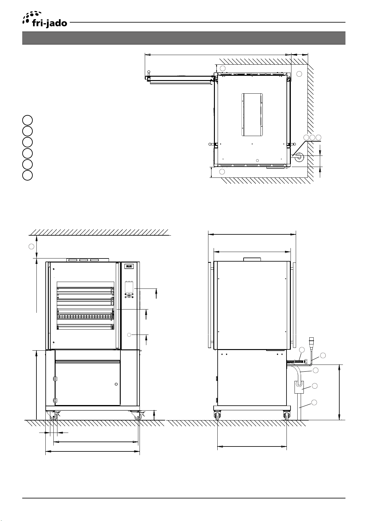
TDR 5 AC
1
Location of mains connection
2
Location of water connectionG 3/4” BSP
3
Location of drain hose OD Ø 33 mm (1 1/16”)
6
Minimum required space
8
Example of funnel
9
Sewer pipe ID ≥ Ø 40 mm (1 5/8”)
>50 (2”)
>50 (2”)
1305 (51 3/8”)
6
6
820 (32 1/4”)
>100 (4”)
6
1 2 3
121
>300 (12”)
6
1735 (68 5/16”)
870 34 3/8”)
710 (27 15/16”)
1420 (56”)
1270 (50”)
935 (36 7/8”)
2
1
3
8
590 (23 1/4”)
9
110 (4 1/4”)
80 (3 1/8”)
777 (30 9/16”)
885 (34 13/16”)
Service Manual TDRacPKII form 9120931 rev. 10/2019
(618 24 5/16”)
Page 15
TDR-ac Installation
TDR 8 AC ON STAND
1
Location of mains connection
2
Location of water connectionG 3/4” BSP
3
Location of drain hose OD Ø 33 mm (1 1/16”)
6
Minimum required space
8
Example of funnel
9
Sewer pipe ID ≥ Ø 40 mm (1 5/8”)
>50 (2”)
>50 (2”)
1615 (63 5/8”)
6
6
>100 (4”)
6
1 2 3
121
>300 (12”)
6
100 (70 5/8”)
780 30 5/8”)
980 (38 1/4”)
860 (33 1/2”)
1470 (58”)
1230 (48 1/2”)
895 (35 1/4”)
2
1
3
8
613 (24 1/8”)
9
Page 16
80 (3 1/8”)
940 (37”)
1050 (41 1/8”)
110 (4 1/4”)
(770 30 1/4”)
Service Manual TDRacPKII form 9120931 rev.10/2019
TDR-ac Installation
TDR 8 AC WITH HOOD
1
Location of mains connection
2
Location of water connectionG 3/4” BSP
3
Location of drain hose OD Ø 33 mm (1 1/16”)
6
Minimum required space
8
Example of funnel
9
Sewer pipe ID ≥ Ø 40 mm (1 5/8”)
1050 (41 1/8”)
>50 (2”)
>50 (2”)
1730 (68 1/8”)
6
6
1080 (42 1/2”)
>50 (2”)
6
1 2 3
121
2126 (83 3/4”)
780 30 5/8”)
80 (3 1/8”)
940 (37”)
1050 (41 1/8”)
375 (14 3/4”)
1830 (72”)
1470 (58”)
1230 (48 1/2”)
895 (35 1/4”)
110 (4 1/4”)
2
1
3
8
613 (24 1/8”)
9
770 (30 1/4”)
Service Manual TDRacPKII form 9120931 rev. 10/2019
Page 17
TDR-ac Installation
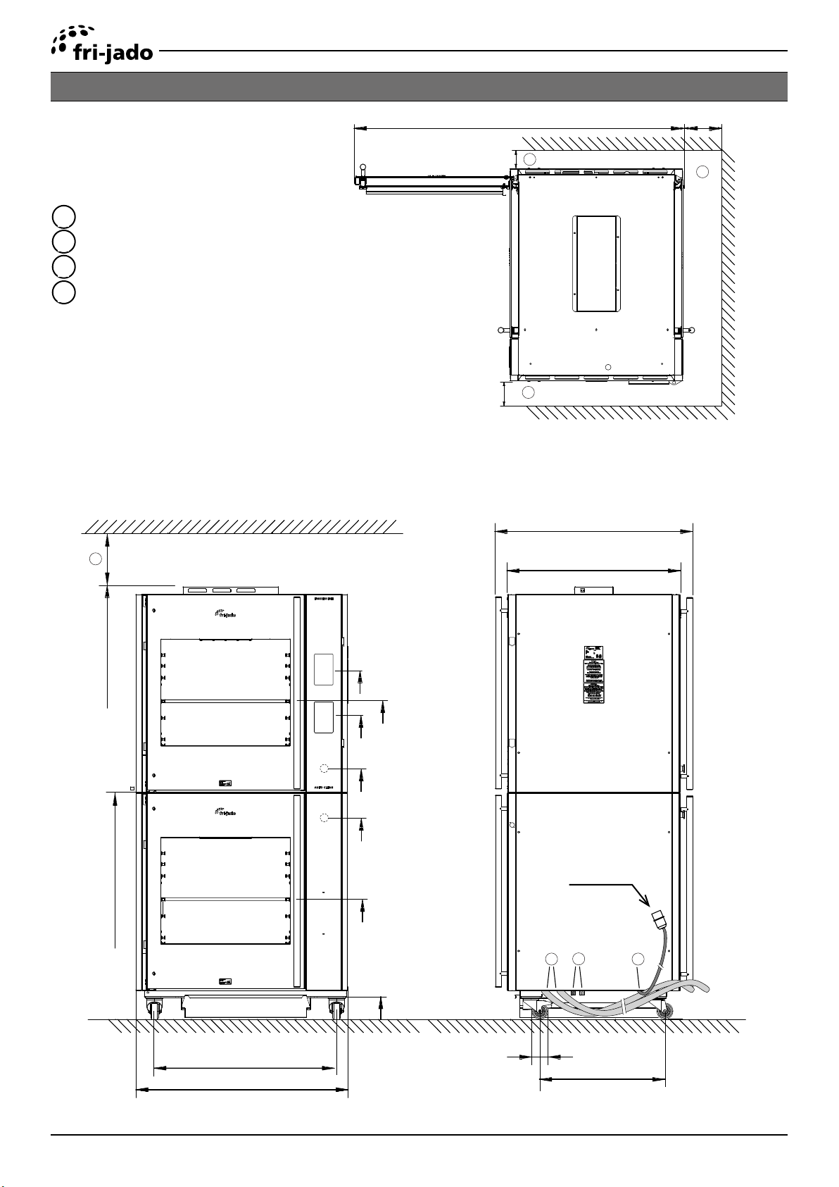
TDR 8+8 AC
1
Location of mains connection
2
Location of water connectionG 3/4” BSP
3
Location of drain hose OD Ø 33 mm (1 1/16”)
6
Minimum required space
Delivered water hose G3/4”, 1,5 mtr (5ft) (2x)
Sewer pipe ID ≥ Ø 40 mm (1 5/8”)
>50 (2”)
>50 (2”)
1615 (63 5/8”)
6
6
980 (38 1/4”)
>100 (4”)
6
>300 (12”)
6
2140 (84 1/4”)
1120 44 1/8”)
1720 (68”)
1570 (62”)
1490 (59”)
1235 (48 5/16”)
1000 (39 3/8”)
600 (23 1/2”)
860 (33 1/2”)
EUR, 1x CEE-form 32A
USA, 2x NEMA 15-50P
2
3
1
Page 18
900 (35 3/8”)
1050 (41 1/8”)
110 (4 1/4”)
80 (3 1/8”)
(615 24 3/16”)
Service Manual TDRacPKII form 9120931 rev.10/2019
TDR-ac Installation
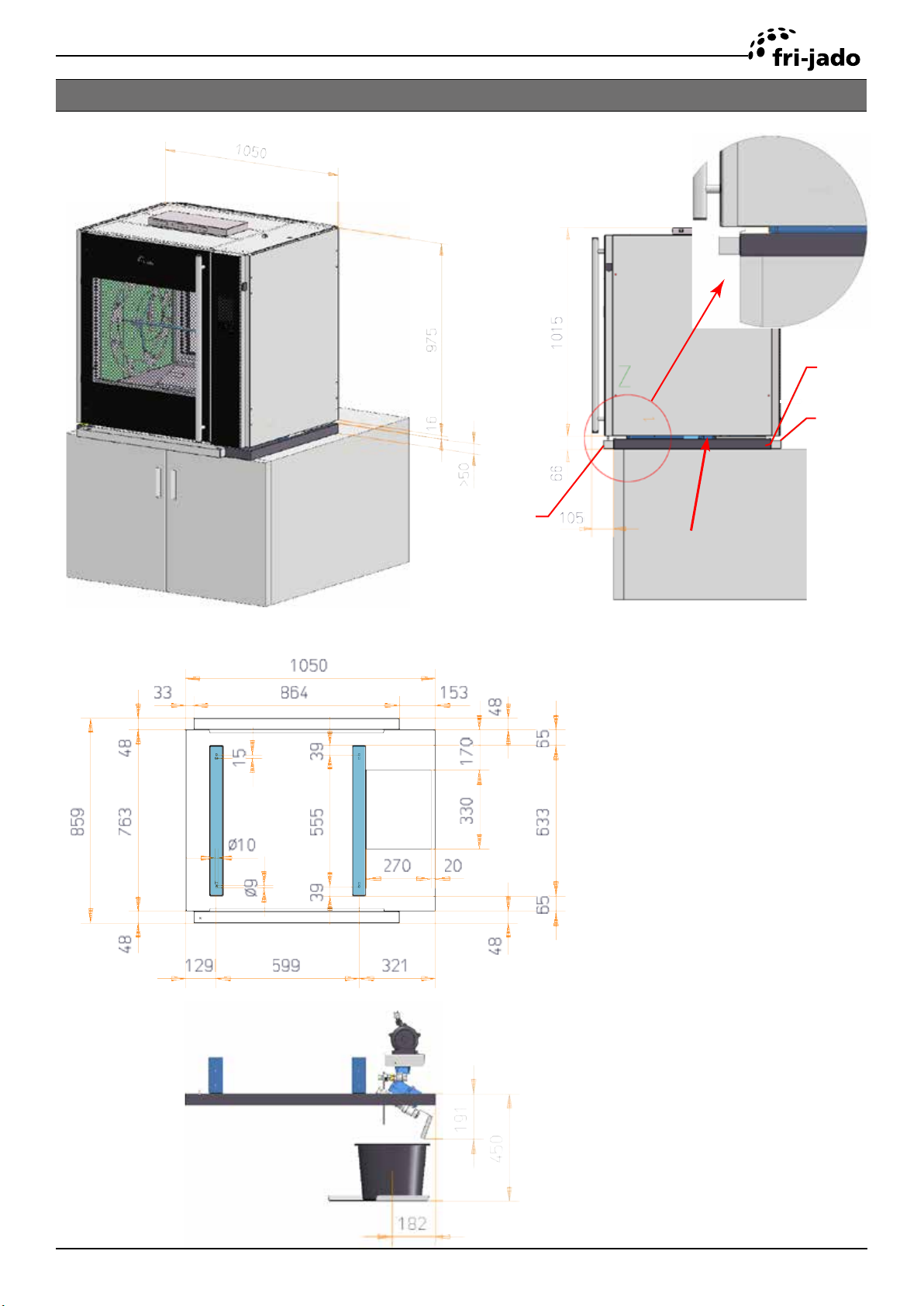
TDR 8 AC ON COUNTER
Support
Driptray
Footprint dimensions, seen from above
Driptray
Space for intake
cooling air
Service Manual TDRacPKII form 9120931 rev. 10/2019
Page 19
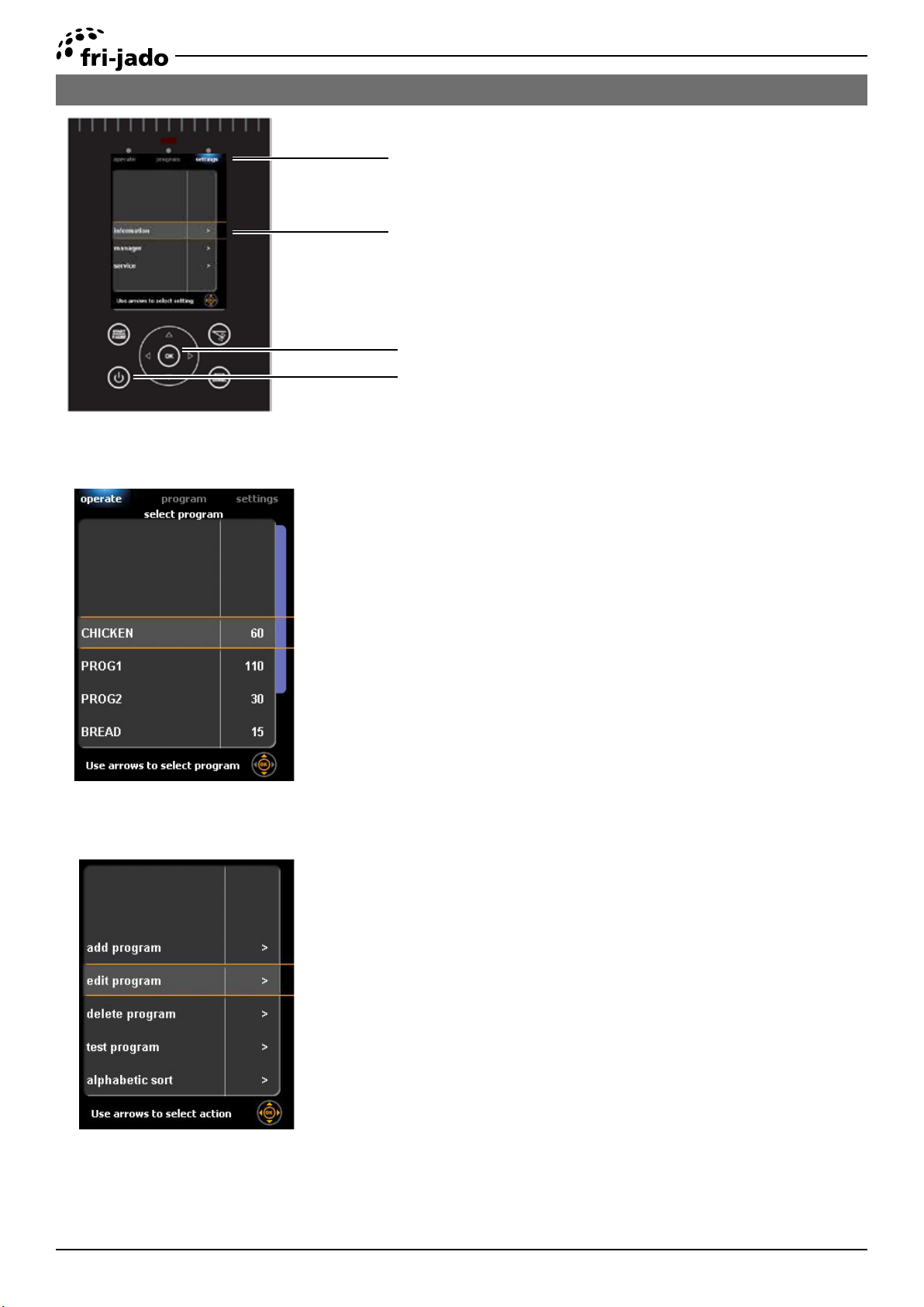
SOFTWARE
MENU SETTINGS TDRAC
To enter the set up of the TDR AC
Selection buttons
press the on/o key for 3 seconds.
The main screen will show 3 options:
Display
Rotation pad
on/ o key
Operate
• operate
• program
• settings
Select the program by pushing the
corresponding key.
The operator menu will allow the user
to run cooking and cleaning programs
Page 20
Program
Within the program menu the user can
edit or add additional cooking programs.
The cooking programs can be “pin
code” protected.
Service Manual TDRacPKII form 9120931 rev.10/2019
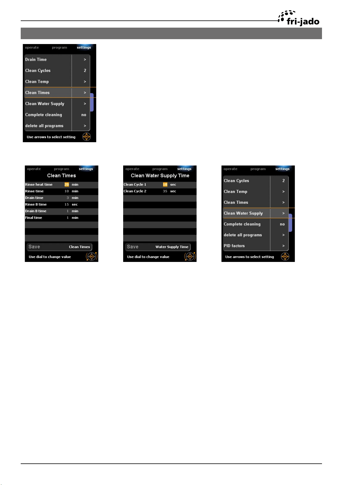
SOFTWARE
CLEANING PROGRAM TDRAC
An overview of the various steps of the cleaning program.
Go to: Settings->service. The amount of time of the various steps
can be adjusted in minutes or seconds.
Service Manual TDRacPKII form 9120931 rev. 10/2019
Page 21
 Loading...