

Fri-Jado STG7-P Service Manual

SERVICE MANUAL
STG7 P GAS FIRED
ROTISSERIE OVEN
MODELS
Programmable controls STG7 P
Gas types G20/25
Model STG7 P Gas
- NOTICE This manual is prepared for the use of trained Service Technicians and
should not be used by those not properly qualified. If you have attended training for this product, you may be qualified to perform all the
procedures in this manual.
This manual is not intended to be all encompassing. If you have not
attended training for this product, you should read, in its entirety,
the repair procedure you wish to perform to determine if you have
the necessary tools, instruments and skills required to perform the
procedure. Procedures for which you do not have the necessary tools,
instruments and skills should be performed by a trained technician.
Reproduction or other use of this Manual, without the express written
consent of Fri-Jado, is prohibited.
WWW.FRIJADO.COM
USA
Service Manual STG7 P Gas form 9123692 rev. 05/2013

Page 2
Service Manual STG7 P Gas form 9123692 rev. 05/2013
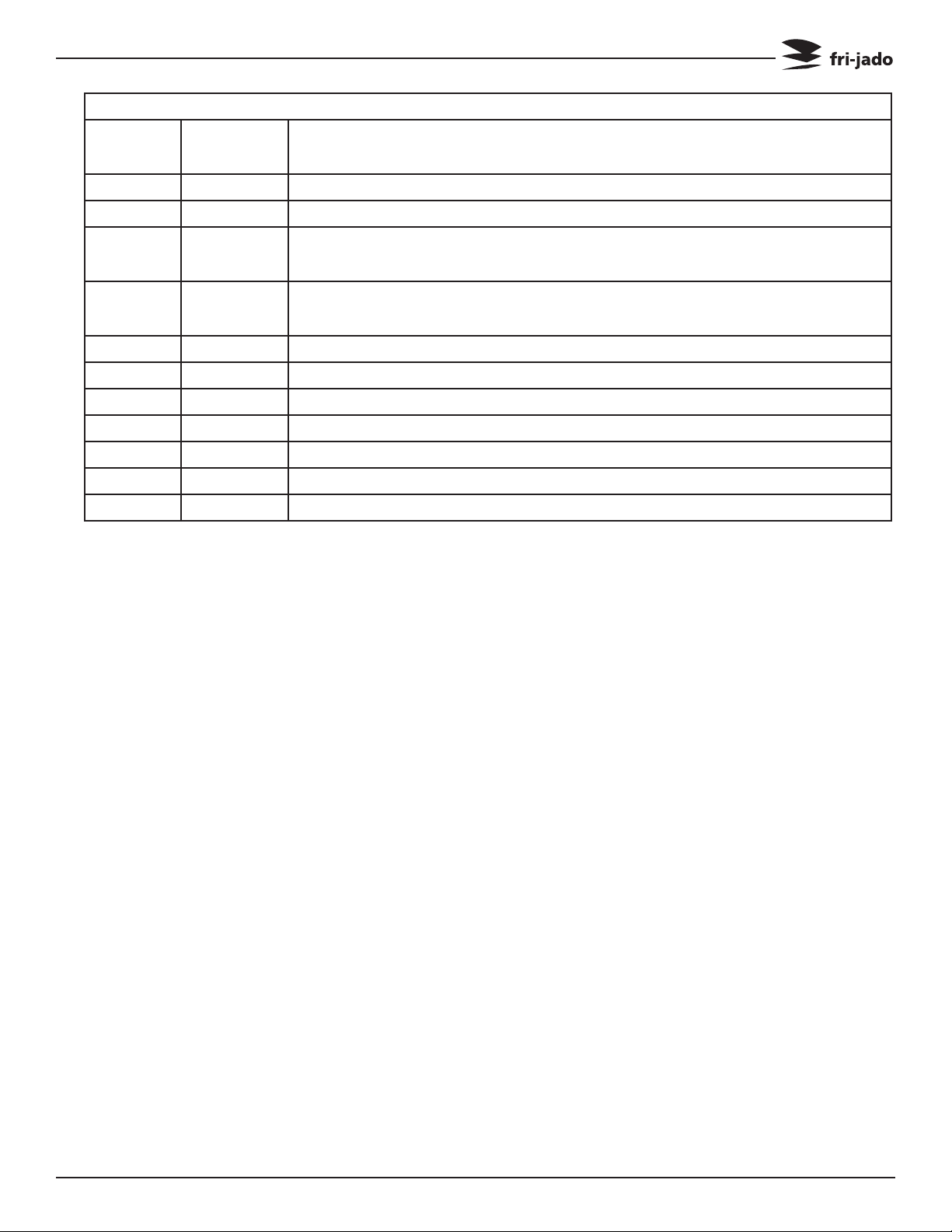
TABLE OF CONTENTS
Versions
Version Issue date
Remarks
dd/mm/yy
02/2009 01/03/2012 First release.
07/2012 01/07/2012 Various adjustments.
02/2013 01/02/2013 Adjusting of power changed. Blower added in electric compart-
ment.
04/2013 01/04/2013 Adjusting power changed on pages 23 to 29. Trouble shooting ad-
justed.
05/2013 01/05/2013 Adjusting power changed on pages 23 to 29.
Service Manual STG7 P Gas form 9123692 rev. 05/2013
Page 3

TABLE OF CONTENTS
INDEX
Index .......................................................................................................................................................... 4
General technical data
Programming instructions
Removal and replacement of parts for the STG7 P Gas
Right or left side panel
Top cover
Knob
Instrument panel
Tumble switch reset
Electric panel
Display
Panel and keypad assembly
Namepanel
Halogen lamp holder (customer side)
Halogen lamp holder (service side)
Power section
Safety thermostat
Main switch
Blower motor
PT500 sensor
Drive motor
Gas mixture blower
Gas burner safety control
Gas control block
Ignition/Ionization set
Board speed control blower
Relay and base relay
Rectifier
Ring core transformers
Door adjustment (left side)
Door glass inside
Door glass outside
Changing an orifice and air inlet
.............................................................................................................................................. 11
..................................................................................................................................................... 11
........................................................................................................................................ 12
.................................................................................................................................................. 13
........................................................................................................................................... 13
....................................................................................................................................... 15
.......................................................................................................................................... 16
....................................................................................................................................... 16
......................................................................................................................................... 17
.......................................................................................................................................... 17
................................................................................................................................................ 20
.............................................................................................................................. 6
........................................................................................................................ 7
........................................................................................................................ 11
................................................................................................................................. 12
............................................................................................................................. 12
................................................................................................................ 13
................................................................................................ 14
.................................................................................................... 14
............................................................................................................................... 15
............................................................................................................................. 18
.................................................................................................................... 18
................................................................................................................................. 19
......................................................................................................................... 19
................................................................................................................ 19
............................................................................................................................ 20
........................................................................................................................ 20
................................................................................................................. 21
.................................................................................................................................. 21
............................................................................................................................... 21
........................................................................................................ 22
....................................................................... 11
Page 4
Service Manual STG7 P Gas form 9123692 rev. 05/2013

TABLE OF CONTENTS
Working of gas fired rotisserie .............................................................................................................. 23
Gas technical data
................................................................................................................................ 24
Electrical tests and service procedures
PT500 sensor test
Keypad test
................................................................................................................................. 25
.......................................................................................................................................... 25
Adjustment of board for speed/power regulation
Temporary bridging of reset switch
Gas block Honeywell type VK4115V
Adjusting of the power for Natural gas and Propane
Ignition/Ionization set
Control location
......................................................................................................................... 30
................................................................................................................................... 31
Troubleshooting for the STG7 P Gas Rotisseries
Exploded views & partlists
STG7 P Gas - sheet iron work
STG7 P Gas - components
Electrical diagrams
.................................................................................................................................. 39
STG7 P Gas - circuit diagram
STG7 P Gas - wiring diagram
..................................................................................................................... 34
.............................................................................................................. 34
.................................................................................................................... 36
............................................................................................................... 39
............................................................................................................... 40
.................................................................................................. 25
............................................................................ 26
................................................................................................... 27
................................................................................................... 28
...................................................................... 29
................................................................................... 32
STG7 P Gas - wiring diagram (till serial number 100054530)
............................................................ 41
Service Manual STG7 P Gas form 9123692 rev. 05/2013
Page 5
GENERAL TECHNICAL DATA
GENERAL TECHNICAL DATA
This manual covers the STG 7 P gas fired rotisserie ovens suitable for G 20/25 (natural gas).
• STG7–Ovenwithsevenspits(28to35chickens).
Alloftheinformation,illustrationsandspecicationscontainedinthismanualarebasedon
thelatestproductinformationavailableatthetimeofprinting.
Note: From Dec. 2008 on the gas pipe ends under the STG 7 instead of at the rear end.
A knee piece and an 8 inch nipple (NPT to BSP thread) are delivered with the unit.
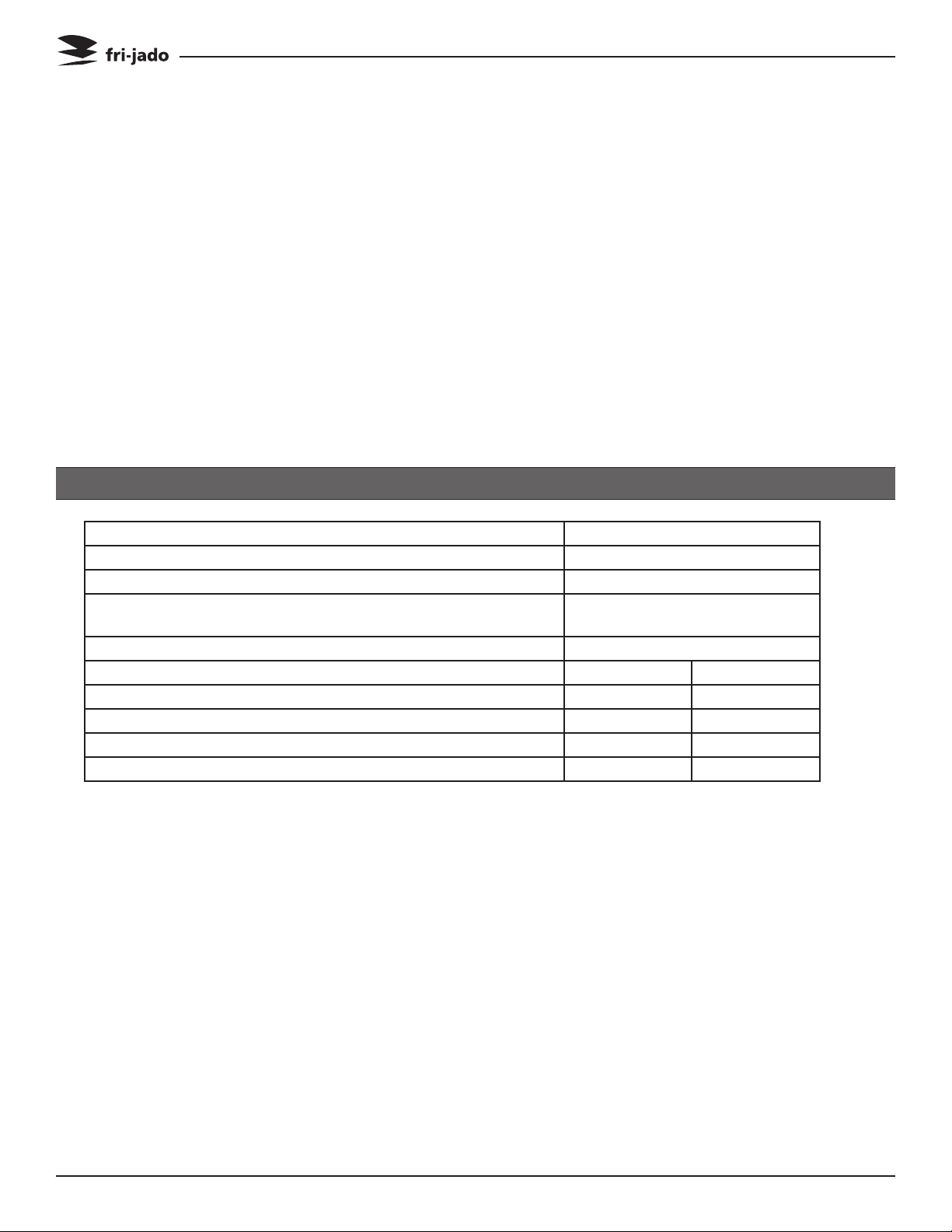
TECHNICAL DATA
Type STG 7
Power(W) 345
Gaspower(BTU-KW) 49.500-14.5
Fusesneededwithpowerconnection115V,1N~50…60Hz
(1phasewithzero)
Standardplugfromfactory NEMA5-15
Netweight 204kg 450lbs
Grossweight 230kg 507 lbs
Height 1025mm 401/4inch
Width 985mm 383/4inch
Depth 850mm 331/2inch
1x15A
Tools
• Standardsetoftools.
• Metricwrenches,socketsandhexsocketkeywrenches.
• Multi-meterandACcurrentclamptester.
• Temperaturetester.
• Insulationvaluetester(Megger).
• Toxicitymeter.
• Gaspressuremeter.
• FieldServiceGroundingKit.
Page 6
Service Manual STG7 P Gas form 9123692 rev. 05/2013
PROGRAMMING INSTRUCTIONS
PROGRAMMING INSTRUCTIONS
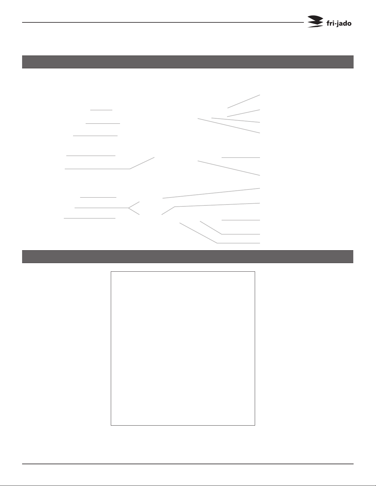
DISPLAY AND KEYS
Time display
Temperature Display
Program indicators
Program keys
Buzzer key
Probe key
Temperature key
Up-Down key
Time key
8888888410 0030
SETTING THE STG
Temperature hold indicator
Second step indicator
First step indicator
Start/Stop
Rotor key
Time of day
Program end
Temperature hold process
Second cooking step
First cooking step
When the main switch is tuned to “1” the
display lights up and the rotisserie is ON.
Service Manual STG7 P Gas form 9123692 rev. 05/2013
Page 7

PROGRAMMING INSTRUCTIONS
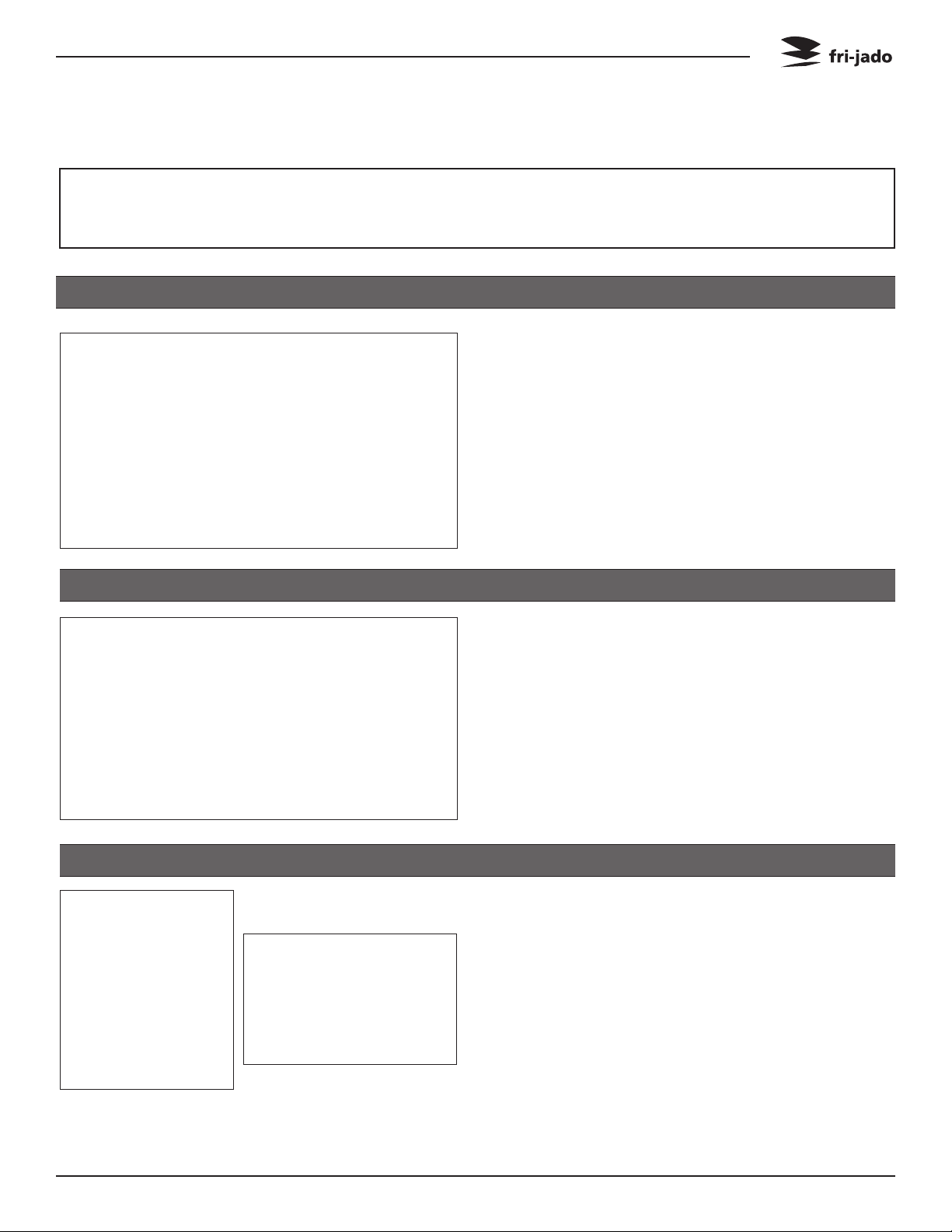
SETTING ACTUAL TIME 15 PROGRAMS
888410 88881040
ENTERING A PROGRAM FIRST COOKING STEP (TIME)
888p01 8888prog
Press and hold Time of
day key
Press Up or Down key
Release Time of day key
Select Program number
Press both Up and Down
keys during 2 seconds
888p16 888815pr
888000 88880040
After the unit is
switched-on the time
display indicates: 15PR
Key 1:
1x = program 01
2x = program 06
3x = program 11
Key 2:
1x = program 02
2x = program 07
3x = program 12
Press Cooking process
key
Cooking symbol lights
up
SECOND COOKING STEP (TIME)FIRST COOKING STEP (TEMP.)
Press and hold the
888410 88880040 888000 88880030
Temperature key
Press Up or Down key
Press and hold the Time
key
Press Up or Down key
Press Grilling process key
Grilling symbol lights up
Press and hold the Time
key
Press Up or Down key
Page 8
Service Manual STG7 P Gas form 9123692 rev. 05/2013

PROGRAMMING INSTRUCTIONS
SECOND COOKING STEP (TEMP.) TEMPERATURE HOLD
888350 88880030
LOADING PROGRAM PROGRAM START & LOADING
888185 88880000
Press and hold Temperature key
Press Up or Down key
Press program number
to load pre-set values
888185 88880000
888000 88880040
Press Temperature Hold
process key
Temperature Hold
symbol lights up
Press and hold the
Temperature key
Press Up or Down key
Press Start / Stop key
On indicator lights up
Press Rotor key to start
turning the rotor
OPTIONAL SETTINGS
INTERRUPTING ACTIVE PROGRAM
Press Rotor key
888350 88880046
Heaters and front lamp
switch off
Rotor stops
On indicator is blinking
Process time in hold
Press Rotor key again to
stop
Load the rotisserie with
products
SET ADDITIONAL BUZZER SIGNAL
Select a pre-defined
888p01 88881055
program
Press and hold Buzzer
key
Press Down key
Service Manual STG7 P Gas form 9123692 rev. 05/2013
Page 9

PROGRAMMING INSTRUCTIONS
SET PROGRAM END TIME DISPLAY SET TIME & TEMPERATURE
Select a pre-defined
888p01 88881030 888390 88880040
ADJUSTING ACTIVE PROGRAM
program
Press and hold the
Program end key
Press Up key
PREHEAT INDICATION
Press and hold Temperature or Time key
888390 88880035 888prh 88880059
Adjust temperature or
time with Up or Down
key
Select a pre-defined
program
Press Cooking, Grilling
or Temperature hold key
No time indication for
Temperature hold
Visible during process or
program selection
Under 40°C (104°F) the
display shows PRH
TEMPERATURE PROBE (OPTIONAL)
Press the Rotor key
888185 88880046
Page 10
Insert the probe in the
meat up to the core
Press Temperature sen-
sor key; after 20 seconds
the temperature reading
switches off
INDICATIONS DURING PROCESS
• Process indicators shows actual process.
After completion indicator switches off
•
Time display shows remaining program
time which is the sum of the remaining
cooking and grilling time
• Temperature display indicates actual temperature in the grill. Under 40°C(104°F)
the display shows PRH (preheat)When
remaining time reaches 0, the process
indicators and the On-indicatorswitches
off
Service Manual STG7 P Gas form 9123692 rev. 05/2013
REMOVAL AND REPLACEMENT OF PARTS
REMOVAL AND REPLACEMENT OF PARTS FOR THE STG7 P GAS
WARNING: Disconnect the electrical power to the machine at the main circuit
box. Place a tag on the circuit box indicating the circuit is being serviced.
RIGHT OR LEFT SIDE PANEL
1. Remove the screws that secure the panel
to the frame.
2. Remove the panel.
3. Reverse the procedure to install.
TOP COVER
1. Remove the left side panel according prior
procedure.
2. Remove the screws securing both large
and small top covers.
3. Remove the small cover.
4. Remove the large top cover. (Lift at left
side and remove to the left).
5. Reverse the procedure to install.
KNOB
1. Remove cover plate on the knob with a
small screw driver.
2. Loosen the screw inside the knob.
3. Remove the knob with ring.
4. Reverse the procedure to install.
Service Manual STG7 P Gas form 9123692 rev. 05/2013
Note: check that the ring behind the knob is
in the right position and runs free from the
panel.
Page 11
REMOVAL AND REPLACEMENT OF PARTS
INSTRUMENT PANEL
1. Remove the right side panel according prior
procedure.
2. Remove the knobs according prior procedure.
3. Remove the screw that secures the panel.
4. Remove the 2 bolts on the backside of the
instrument panel.
5. Remove the screws that secure the meat
probe holder and remove the holder (if
supplied).
6. Remove the flatcable on the power section.
7. Remove the clip on the back, top left side
that secures panel and frame.
8. Remove the instrument panel.
9. Reverse the procedure to install.
TUMBLE SWITCH RESET
1. Remove the right side panel according prior
procedure.
2. Remove the wiring.
3. Remove the switch by pushing the clamps
with a screw driver.
4. Reverse the procedure to install.
ELECTRIC PANEL
1. Remove the instrument panel according
prior procedure.
2. Remove on the front side the screws that
secure the panel.
3. Remove on the inside bottom of the electric panel the bolt and nuts.
4. Disconnect the wiring.
5. Slide the electrical panel backwards.
6. Reverse the procedure to install.
Page 12
Service Manual STG7 P Gas form 9123692 rev. 05/2013

REMOVAL AND REPLACEMENT OF PARTS
DISPLAY
1. Remove the right side panel according
prior procedure.
2. Disconnect the flatcable on the display.
3. Remove the clip on the back, top left side
that secures panel and frame.
4. Remove the nuts and washers on the backside of the display and remove the metal
cover.
5. Remove the nuts and plastic rings that
secure the board and remove the board. Do
not forget to disconnect the blue connector
on the board.
6. Reverse the procedure to install.
PANEL AND KEYPAD ASSEMBLY
1. Remove the instrument panel according
prior procedure.
2. 2. Remove the display according prior
procedure.
3. Remove the nuts that secure the panel with
foil and remove panel.
4. Reverse the procedure to install.
NAMEPANEL
1. Remove the instrument panel according
prior procedure.
2. Remove the 4 nuts that secure the panel
and remove panel.
3. Reverse the procedure to install.
Service Manual STG7 P Gas form 9123692 rev. 05/2013
Page 13
REMOVAL AND REPLACEMENT OF PARTS
HALOGEN LAMP HOLDER (CUSTOMER SIDE)
1. Remove the top cover according prior
procedure.
2. Remove the wiring of the lamp on the
connector.
3. Remove the cap nuts that secure the air
suction plate and remove this plate.
4. Remove the glass and lamp from the lamp
holder. Turning direction of glass in counter
clockwise.
5. Remove the holder. You have to deform the
holder to take it out.
6. Insert a new holder and click this in.
7. Reverse the procedure to install.
Page 14
HALOGEN LAMP HOLDER (SERVICE SIDE)
1. Remove the top cover according prior
procedure.
2. Remove the wiring of the lamp on the
connector.
3. Remove the glass and lamp from the lamp
holder. Turning direction of glass in counter
clockwise.
4. Remove the holder. You have to deform the
holder to take it out.
5. Insert a new holder and click this in.
6. Reverse the procedure to install.
Service Manual STG7 P Gas form 9123692 rev. 05/2013
 Loading...