

Fri-Jado STG5 Installation Manual
INSTRUCTIONS
STG - ROTISSERIE OVEN MODELS
STW - WARMER MODELS
MODELS
Prog. Controls STG5-P
STG7-P
STG7-P-GAS
Intelligent STG5-i
STG7-i
Warmers STW5
STW7
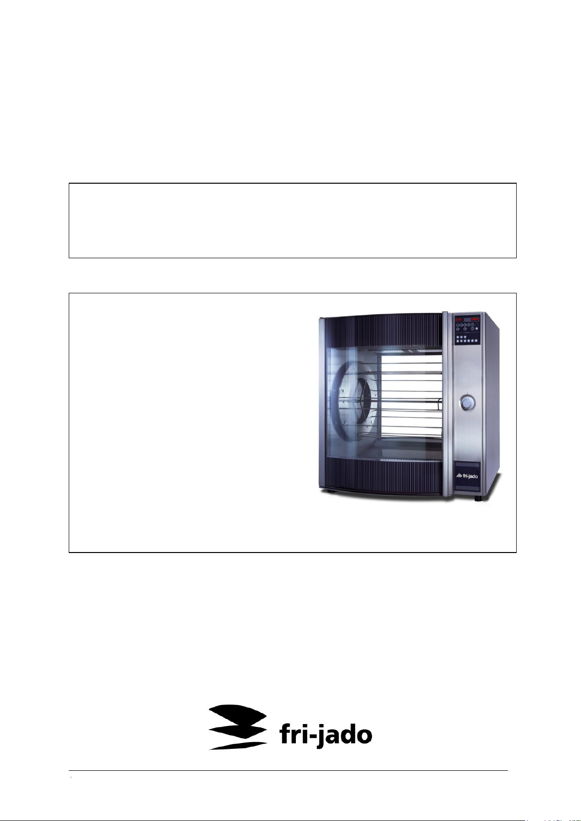
Model STG7-P
● IMPORTANT ●
READ BEFORE USING ROTISSERIE/WARMER
Installation, operation and care of
www.frijado.com
Part-number form 912.3476 0904

2
TABLE OF CONTENTS
MODELS .................................................................................................................... 3
GENERAL .................................................................................................................. 6
Features and options .............................................................................................. 6
Ovens ...................................................................................................................... 7
Warmers ................................................................................................................. 7
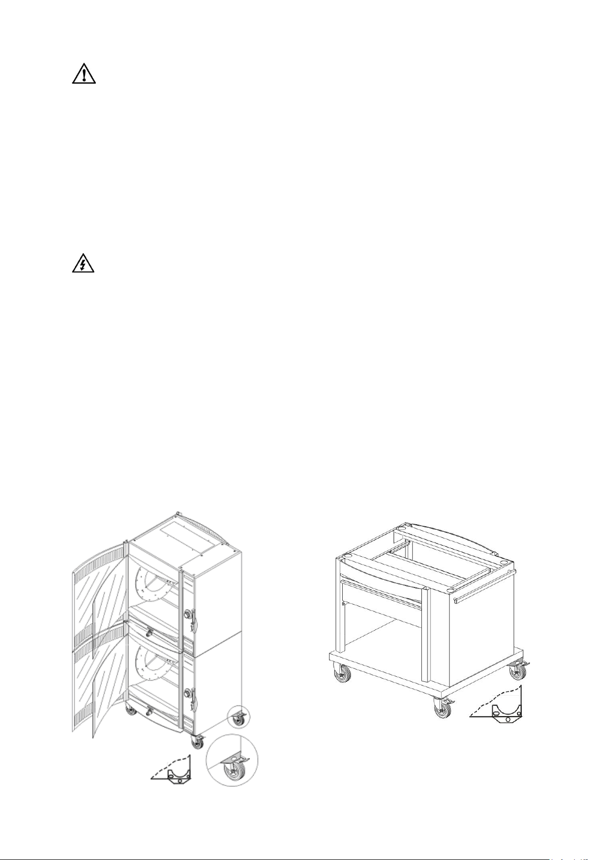
Stacking .................................................................................................................. 7
1. INSTALLATION ...................................................................................................... 8
1.1 Location ............................................................................................................ 8
1.2 Legs / casters .................................................................................................... 9
1.3 Supplemental installation instructions ............................................................... 9
1.4 Installation codes and standards ..................................................................... 10
1.5 Electrical connections ..................................................................................... 11
1.6 Electrical data.................................................................................................. 12
1.7 STG7-P-GAS only: Gas connection ................................................................ 13
1.8 STG7-P-GAS only: Gas pressures and orifices .............................................. 13
1.9 STG7-P-GAS only: Flue connections .............................................................. 13
2. BEFORE FIRST USE ........................................................................................... 14
3. OPERATION ........................................................................................................ 14
3.1 Control panels ................................................................................................. 15
3.2 Programmable controls ................................................................................... 16
3.3 Intelligent oven control panel .......................................................................... 22
3.4 Preparing the product ...................................................................................... 36
3.5 Loading products onto accessories ................................................................ . 36
3.6 Loading accessories into the oven .................................................................. 39
3.7 Unloading accessories from the oven ............................................................. 41
3.8 Suggested roasting guidelines ........................................................................ 42
3.9 Emptying grease drawer ................................................................................. 43
3.10 Warmer controls ................................................................ ............................ 44
3.11 Using warmers (models STW5 and STW7)................................................... 44
4. CLEANING ........................................................................................................... 45
4.1 Cleaning stainless steel surfaces .................................................................... 45
4.2 Cleaning non-stick coated surfaces ................................................................ 46
4.3 Cleaning probe ................................................................................................ 47
4.4 Cleaning grease drawer .................................................................................. 47
4.5 Cleaning warmers ........................................................................................... 47
4.6 Cleaning quartz lamps .................................................................................... 48
4.7 Monthly cleaning (or more often if necessary)................................................. 48
5. MAINTENANCE ................................................................................................... 48
3
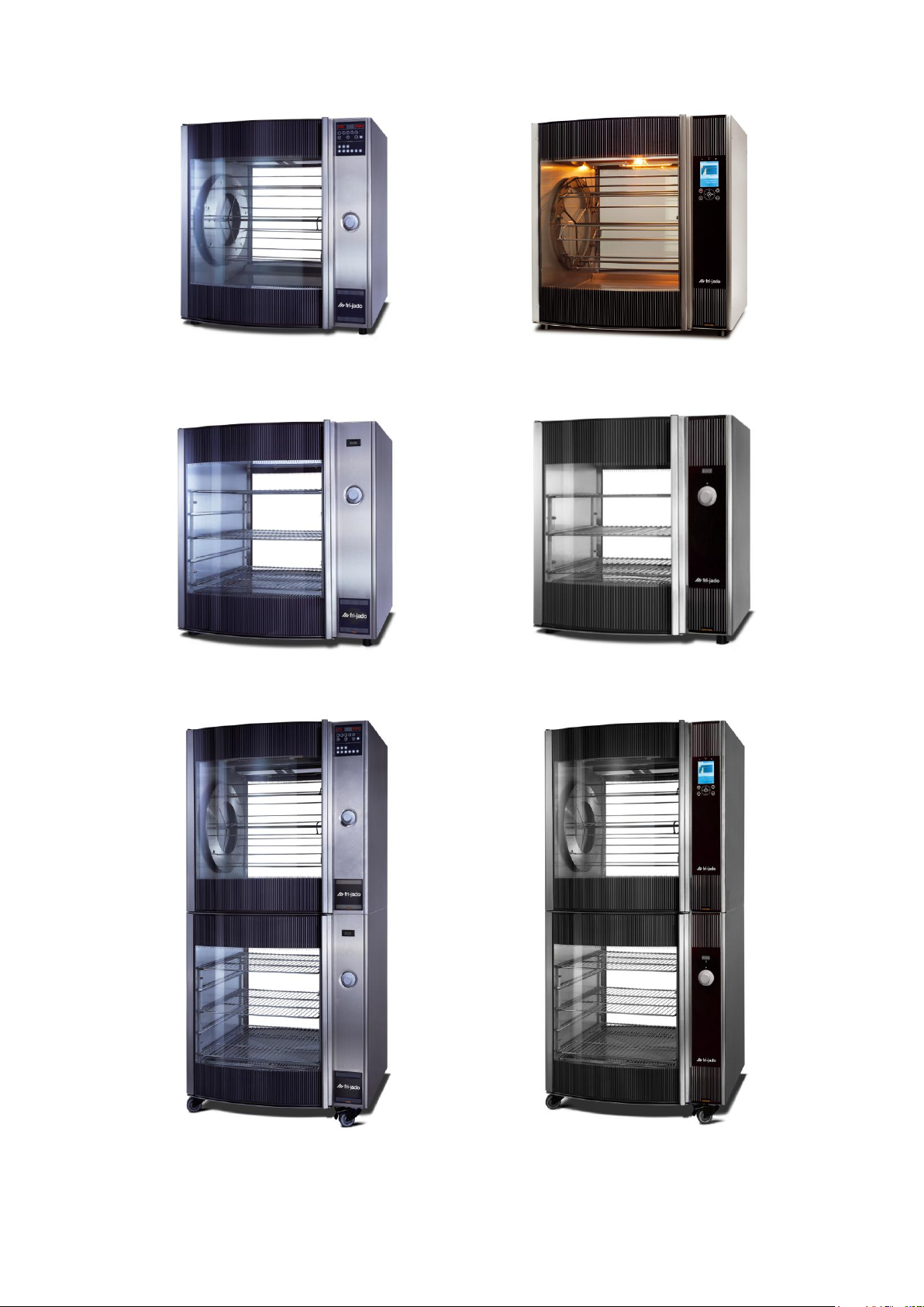
MODELS
Model STG5-P, STG7-P and STG7-P-GAS
Oven
(STG7-P displayed)
Model STG5-i and STG7-i Oven
(STG7-i displayed)
Model STW5 and STW7 Warmer
(STW7 displayed)
Model STW5 and STW7 Warmer
(STW7 displayed)
Model STG5-P Oven / STW5 Warmer and
STG7-P Oven / STW7 Warmer (displayed)
Model STG5-i Oven / STW5 Warmer and
STG7-i Oven / STW7 Warmer (displayed)
• Rotisserie ovens with Programmable Controls shown; meat probe is optional

4
5
Installation, Operation and Care of
=
WARNING
Failure to observe this warning may result in personal injury, death, or
equipment damage.
=
WARNING
Risk of electrical shock. Failure to observe this warning may result in
personal injury, death, or equipment damage.
=
WARNING
Hot! Risk of burns. Wear heat-protective gloves.
STG - ROTISSERIE OVEN MODELS AND
STW – WARMER MODELS
BEFORE USING THE OVEN OR WARMER FOR THE FIRST TIME,
CAREFULLY READ THIS ENTIRE MANUAL.
IMPORTANT NOTICE: The user is responsible for reading and following
these instructions to ensure the safe and proper installation, operation,
and maintenance of the ovens and warmers. The manufacturer
expressly disclaims any and all liability for any and all damage or injury
resulting from failure to follow and comply with these instructions, or
from failure to exercise reasonable care in the handling, operation,
cleaning, and repair of the ovens and warmers, and failure to explicitly
include any warnings or instructions in this manual shall not give rise to
any claim for damages. If you have any questions concerning the
installation, operation, care, or maintenance of the ovens or warmers
that are not covered by these instructions, please contact the
manufacturer at:
Fri-Jado Inc.
877 – 374 – 5236 (toll free)
SAFETY SYMBOLS
The following symbols are used throughout this manual to alert the user to specific
hazards:
Please read the safety instructions in this manual carefully and use the ovens
and warmers only as described in these instructions to avoid injury or damage.
KEEP THESE INSTRUCTIONS FOR FUTURE REFERENCE!
© 2008 Fri-Jado BV, Etten-Leur, The Netherlands
Customers are permitted to copy these instructions for private use.

6
V-Spit
Turkey
Spit
Basket
Chicken rack
Meat
forks
Warmer
shelves
3 rack
4 rack
5 rack
STG5
5 1 5 5 NA
NA 5 NA
STG7
7
1 7NA 7 7 7 NA
STW5
NA
NA
NA
NA
NA
NA
NA
3
STW7
NA
NA
NA
NA
NA
NA
NA
3
GENERAL
The Fri-jado STG Series Rotisserie Ovens and STW Warmers feature model wide
tempered glass doors, both front and back. On the ovens, however, the back door
may be replaced by a closed insulated panel. Bright quartz lighting promotes visual
appeal.
The interior and exterior are made of stainless steel for good cleaning. The inside of
the closed insulated panel, the rotor system and the accessories are provided with a
non- stick coating for even better cleaning ability.
Ovens and warmers are available in two sizes:
STG5 - Oven with 5 spits (15-20 chickens)
STW5 - Warming cabinet
STG7 - Larger oven with 7 spits (28-35 chickens)
STW7 - Warming cabinet
FEATURES AND OPTIONS
Quantity per oven. All parts are optional.
Do not mix accessories on the rotor.
A Probe to measure the core temperature of the product is an option.
THIS PRODUCT HAS A ONE-YEAR WARRANTY FOR PARTS AND LABOR. PARTS THAT ARE
NOT COVERED BY THIS WARRANTY ARE LAMPS AND GLASS. THE SOLE AND EXCLUSIVE
REMEDY OF THE PURCHASER IS LIMITED TO REPAIR OR REPLACEMENT OF THE PRODUCT,
AT THE SOLE DISCRETION OF FRI-JADO, INC. THIS LIMITED REPAIR AND REPLACEMENT
WARRANTY IS THE SOLE WARRANTY PROVIDED FOR THIS PRODUCT AND FRI-JADO, INC.
EXPRESSLY EXCLUDES AND DISCLAIMS ALL OTHER WARRANTIES, INCLUDING
MERCHANTABILITY AND FITNESS FOR A PARTICULAR PURPOSE. THIS WARRANTY IS VOID
WHERE DAMAGE RESULTS FROM IMPROPER USE OF THE PRODUCT OR THE PURCHASER
USES THE PRODUCT IMPROPERLY.

7
OVENS
Top
Bottom
STG7-P
STG7-I
STG7-P-GAS
STG7-P
STG7-I
STW7
Same size wheeled base
STG5-P
STG5-I
STG5-P
STG5-I
STW5
Same size wheeled base
The ovens are provided with programmable control operation.
The STG ovens use self-basting spits with optional chicken racks, meat forks, or
baskets. The rotation of the spits, racks, meat forks or baskets with the combination
convection and radiant heat provide thorough cooking and even browning in the
oven. The oven's grease drawer has a drain valve for elimination of excess fat and
can be completely removed for cleaning.
WARMERS
The STG warmers feature low velocity, high humidity air circulation which keeps
foods moist. The STW warming cabinets have three shelves.
STACKING
Units may, ex factory, be stacked in the following combination:
Stacked units each have their individual power supply.
8
1. INSTALLATION
WARNING
Prior to installation, test the electrical service to assure that it agrees with the
specifications on the machine data plate located on the right side panel near
the controls.
WARNING
For STG7-P-GAS only : Prior to installation, test the gas supply (natural or
propane) to assure that it agrees with the specifications on the machine data
plate located on the right side panel near the controls.
WARNING
Appliances equipped with a flexible electric supply cord are provided with a
three- or four-prong grounding plug. This plug must be connected into a
properly grounded three-prong receptacle. If the receptacle is not the proper
grounding type, contact an electrician. Do not remove the grounding prong
from this plug.
WARNING
A minimum wall clearance of 10” (254 mm) from any glass, and 4" (102 mm)
from each side panel must be maintained.
WARNING
For STG7-P-GAS only : The oven must be installed so that the flow of
combustion and ventilation air will not be obstructed. Make sure there is an
adequate supply of air in the room to allow for that required for combustion of
gas at the oven burner
WARNING
Make sure that the windows stay out of the reach of children. During the grill
process the windows get hot.
Immediately after unpacking the oven or warmer, check for possible shipping
damage. If oven or warmer is found to be damaged after unpacking, save the
packaging material and contact the carrier within 15 days of delivery.
1.1 LOCATION
The oven may be placed where cooking may be observed to enhance customer
awareness and must be installed on a level surface.
The installation location must allow adequate clearances for servicing and for proper
operation of the front and rear doors.
Keep the space around the bottom and the ventilation opening in the top of the STG
free of obstacles to guarantee a good air flow in the electrical compartment and
combustion chamber .
9
WARNING
Do not store or use gasoline or other flammable vapors or liquids in the
vincinity of this appliance
WARNING
1.2 LEGS / CASTERS
Each oven and warmer is furnished on 2” (50 mm) legs. Stacked units are provided
with casters.
1.3 SUPPLEMENTAL INSTALLATION INSTRUCTIONS
(For model STG(W) 5 and STG(W) 7 units for fixed wiring and stacked or placed
on bases with casters)
Safety standards require that, when this appliance is properly connected to the
electrical power supply using a permanently connection, adequate means be
provided to limit movement of the appliance without depending on or transmitting
stress to the electrical conduit. This means that, as part of the installation, the
base or bottom unit of stacked models must be secured to the building
structure (typically either wall or floor) to limit the movement of the appliance
and, thus, helping to prevent damage to the conduit during cleaning,
maintenance and service operations.
A tether bracket, as shown on the drawing below, is provided with the base or
stacking kit. Based on the routing of the flexible conduit, the bracket must be installed
along with the caster to one corner of the base using the hardware provided. The
remaining open hole in the center of the tether bracket is to be used to secure one
end of the tether (locally supplied chain, cable, etc.). The other end of the tether is to
be secured to an anchoring point in the building structure. Note: Length of tether
must be shorter than the flexible conduit to make sure that during appliance
movement, no stress is transmitted to the conduit.

10
Following installation, check to confirm that, when the appliance is moved to
the limits of the tether in each direction, no stress is transmitted to the electrical
conduit.
If it is necessary to disconnect the restraint, first turn off the gas supply.
Reconnect the restraint before turning the gas supply on and returning the
oven to its original installation position.
Following installation, check to confirm that, when the appliance is moved to
the limits of the tether in each direction, no stress is transmitted to the piping of
the gas supply.
For STG7-P-GAS only:If the oven is to be installed with casters, the installation shall
be made with a connector complying to the Standard for Connectors for Movable Gas
Appliances ANSI-Z21.69 (latest edition), and a quick-disconnect device that complies
with the Standard for Disconnect Devices for Use with Gas Fuel, ANSI-Z21.41 (latest
edition).Provide a gas line strain relief to limit the movement of the oven without
depending on the connector and the quick-disconnect device or its associated piping
to limit oven movement.
Note:
Units may be delivered completely stacked or placed on a base.
1.4 INSTALLATION CODES AND STANDARDS
In the United States, all STG series ovens and STW series warmers or combinations
must be installed according to the following codes:
State and local codes.
National Electric Code, ANSI/NFPA 70 (latest edition). available from National
Fire Protection Association, 1 Batterymarch Park, Quincy, MA 02269.
National Fuel Gas Code, ANSI-Z223.1/NFPA 54 (latest edition), available from
National Fire Protection Association,1 Batterymarch Park, Quincy, MA 02269.
ANSI/NFPA 96, ” Standard for Ventilation Control and Fire Protection of
Commercial Cooking Operations” (latest edition), available from National Fire
Protection Association, 1 Batterymarch Park, Quincy, MA 02269.
In Canada, all STG series ovens and STW series Warmers or combinations must be
installed according to the following codes:
Local codes.
Canadian Electric Code, CSA C22.1 (latest edition) available from the
Canadian Standard Association, 178 Rexdale Boulevard, Toronto, Ontario,
CANADA, M9W 1R3
11
CAN/CGA-B149.1, “Installation for Natural Gas Burning Appliances and
WARNING
Electrical and grounding connections must comply with the applicable
portions of the national electrical code and / or other local electrical codes.
WARNING
Disconnect electrical power supply and place a tag at the disconnect switch
indicating that you are working on the circuit.
WARNING
Appliances equipped with a flexible electric supply cord are provided with a
three-prong grounding plug. This plug must be connected into a properly
grounded three-prong receptacle. If the receptacle is not the proper
grounding type, contact an electrician. Do not remove the grounding prong
from this plug.
WARNING
Ensure that the electrical power supply agrees with the specifications on the
oven's data plate and complies with the wiring diagram, located behind the
oven side panel and under the drive motor.
WARNING
For STG7-P-GAS only : Do not turn on the power supply on until after the gas
connections have been made and checked for leaks.
Equipment” (latest edition) available from the Canadian Standard Association,
178 Rexdale Boulevard, Toronto, Ontario, CANADA, M9W 1R3.
CAN/CGA-B149.2 , “Installation for Propane Burning Appliances and
Equipment” (latest edition) available from the Canadian Standard Association,
178 Rexdale Boulevard, Toronto, Ontario, CANADA, M9W 1R3.
1.5 ELECTRICAL CONNECTIONS
Access the electrical connection point by removing the side panel(s) where the
controls are located.
Refer to the ELECTRICAL DATA chart on the next page.

12
1.6 ELECTRICAL DATA
MODEL
VOLTS
HERTZ
PHASE
CIRCUIT SIZE*
(AMPS)
STG5
208
208
240
240
60
60
60
60
1
3
1
3
35
20
35
20
STG7
208
208
240
240
60
60
60
60
1
3
1
3
60
35
60
35
STG7-P-GAS
115
60 1 3
STW5
208
208
240
240
60
60
60
60
1
3
1
3
15
10
15
10
STW7
208
208
240
240
60
60
60
60
1
3
1
3
15
15
20
15
STACKED MODELS
(2) STG5
208
208
240
240
60
60
60
60
1
3
1
3
(2) 35
(2) 20
(2) 35
(2) 20
(2) STG7
208
240
60
60 3 3
(2) 35
(2) 35
(2) STW5
208
208
240
240
60
60
60
60
1
3
1
3
30
-
35
-
(2) STW7
208
208
240
240
60
60
60
60
1
3
1
3
30
35
40
30
STG5 & STW5
208
208
240
240
60
60
60
60
1
3
1
3
35 + 30
-
35 + 35
-
STG7 & STW7
208
208
240
240
60
60
60
60
1
3
1
3
35 + 30
35 + 35
35 + 40
35 + 30
STG7-P-GAS & STG7
115 & 208
115 & 208
115 & 240
115 & 240
60
60
60
60
1 & 1
1 & 3
1 & 1
1 & 3
3 + 60
3 + 35
3 + 60
3 + 35
STG7-P-GAS & STW7
115 & 208
115 & 208
115 & 240
115 & 240
60
60
60
60
1 & 1
1 & 3
1 & 1
1 & 3
3 + 15
3 + 15
3 + 20
3 + 15
Maximum Circuit Breaker size / minimum circuit amperage compiled in accordance
with the National Electric Code (latest edition).

13
1.7 STG7-P-GAS only: Gas connection
WARNING
Check all joints in the gas supply line for leaks prior to starting.
Use soap and water solution. Do not use an open flame.
WARNING
Disconnect the oven from the gas supply piping system during any pressure
testing on the gas supply piping system.
All gas supply connections and any pipe joint compound used must be resistant to
the action of propane gases.
Codes require that a gas shutoff valve be installed in the gas line ahead of the oven.
The gas inlet is located on the rear panel near the bottom.
Connect the oven to the gasline after leveling. Gas supply line must be at least the
equivalent of 1/2 “ (12.7 mm) iron pipe. Make sure the pipes are clean and free of
obstructions, dirt, and piping compound.
After piping has been checked for leaks, fully purge gas pipes to remove air.
1.8 STG7-P-GAS only: Gas pressures and orifices
Natural Gas
The burner orifices are sized to deliver the nameplate input rating at a gas manifold
pressure of 6” (152.4 mm) W.C. (water column). The gas pressure regulator is
integral to the gas solenoid valve, and is factory set to supply 6” (152.4 mm) W.C.
(water column) as required for natural gas.
Propane gas
The burner orifices are sized to deliver the nameplate input rating at a gas manifold
pressure of 10” (254 mm) W.C. (water column). The gas pressure regulator is integral
to the gas solenoid valve, and is factory set to supply 10” (254 mm) W.C. (water
column) as required for propane gas.
1.9 STG7-P-GAS only: Flue connections
Ventilation requirements will vary with each installation and must comply with
applicable portions of NFPA Standard #96 and with local codes. Considerations to be
kept in mind include :
Flue connections should never be made directly to the oven.
The oven should be located under a hood which has adequate connection to
an exhaust duct and extends 6” (15 cm) beyond the oven sides.
Clearance above the oven flue should be adequate for the products to escape
so that there is no interference with the heat circulation in the oven. Refer to
ANSI/NFPA 96, ” Standard for Ventilation Control and Fire Protection of
Commercial Cooking Operations” (latest edition).
14
2. BEFORE FIRST USE
WARNING
Disconnect electrical power before cleaning.
WARNING
In the event of powerfailure, do not attempt to operate this device
WARNING
Hot glass, grease, and parts can cause burns. Use care when operating and
servicing the oven.
WARNING
Check the grease drawer after each cooking process and empty already when
about half full to avoid overflowing. Push the grease drawer completely into the
oven after placing it back to prevent damage to the window.
Refer to EMPTYING GREASE DRAWER.
WARNING
STG7-P-GAS only : In the event a gas odor is detected, shut down units at
main shutoff valve and contact the local gas company or gas supplier for
service.
Oven must be "burned in" to release any odors that might result from heating the new
oven surfaces.
1. Clean oven, accessories, and warmer (if present), both inside and outside, with
warm soapy water. Refer to "Cleaning" in this manual for further
instructions.
2. Rinse thoroughly and wipe dry with a soft clean cloth. Avoid water contact
with quartz lamps.
3. Operate oven at maximum temperature setting of 480°F (250°C) for 45 minutes.
When provided, operate the warmer at maximum thermostat setting (mark 5) for
45 minutes.
Smoke with an unpleasant odor will normally be given off during this burn-in
period. Provide adequate room ventilation and avoid inhaling.
3. OPERATION
15
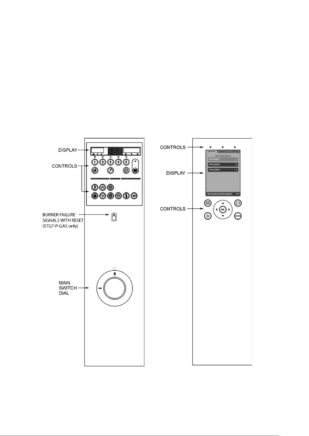
3.1 CONTROL PANELS
Programmable oven control panel
(STG-P)
Shows “Program 1” and “15Pr” when
first turned on.
Colon flashes, remaining cooking time
shows.
For operating instructions for the
programmable control (STG-P) see
„3.2 Programmable oven control panel‟.
Intelligent oven control panel (STG-i)
The STG control panel is equipped with
a large LCD display. Above and below
this screen are touch sensitive keys
that control the oven.
For operating instructions for the
intelligent control (STG-i) see
„3.3 Intelligent oven control panel‟.
 Loading...