

Fri-Jado FJ 1000 Service Manual
SERVICE MANUAL
FRI-JADO FJ 1000
STG - ROTISSERIE OVEN MODELS
STW - WARMER MODELS
MODELS FJ1000*
Programmable controls STG5 P
STG7 P
Warmers STW 5
STW 7
* Fri-Jado produced Programmable Rotisseries and Warmers with serial numbers starting with 1000
- NOTICE -
This manual is prepared for the use of trained Service Technici-
ans and should not be used by those not properly qualified. If
you have attended training for this product, you may be quali-
fied to perform all the procedures in this manual.
This manual is not intended to be all encompassing. If you have
not attended training for this product, you should read, in its
entirety, the repair procedure you wish to perform to determine
if you have the necessary tools, instruments and skills required
to perform the procedure. Procedures for which you do not have
the necessary tools, instruments and skills should be performed
by a trained technician.
Reproduction or other use of this Manual, without the express
written consent of Fri-Jado, is prohibited.
USA
WWW.FRIJADO.COM
Service Manual STG5/7 STW5/7 form 9123647 rev. 03/2014

PAGE
Page 2
Service Manual STG5/7 STW5/7 form 9123647 rev. 03/2014
TABLE OF CONTENTS
Versions
Version Issue date
Remarks
dd/mm/yy
01/2012 05/01/2012 Switch, castors and electric diagrams adjusted.
03/2014 01/03/2014 Textual changes. Troubleshooting adapted. Exploded views modified.
Service Manual STG5/7 STW5/7 form 9123647 rev. 03/2014
Page 3

INDEX
Index .......................................................................................................................................................... 4
General technical data
Technical Data U.S. Standard Models ................................................................................................... 6
Technical Data U.S. Special Models
Programming instructions for the STG5 / STG7 and STW5 / STW7
Optional settings for the STG5 and STG7
Removal and replacement of parts for the STG5 and STG7
Right or left side panel
Top cover .............................................................................................................................................. 11
Knob ..................................................................................................................................................... 12
Operating panel ................................................................................................................................... 12
Electric panel
Display
.................................................................................................................................................. 13
........................................................................................................................................ 13
Panel and keypad assembly ................................................................................................................ 14
Namepanel ........................................................................................................................................... 14
Power and I/O board ........................................................................................................................... 14
Quartz lamp ......................................................................................................................................... 15
Main switch .......................................................................................................................................... 15
High limit thermostat .......................................................................................................................... 16
Contactor .............................................................................................................................................. 16
Heating element .................................................................................................................................. 17
Blower motor ....................................................................................................................................... 17
Blower motor bottom rotisserie (stacked STG) .................................................................................. 18
PT500 sensor ......................................................................................................................................... 18
Drive motor .......................................................................................................................................... 19
Door adjustment (left side) ................................................................................................................. 20
Door inside ........................................................................................................................................... 20
Door outside ........................................................................................................................................ 21
Removal and replacement of parts for the STW 5 and STW 7
Blower motor ....................................................................................................................................... 22
Thermometer ....................................................................................................................................... 22
Thermostat ........................................................................................................................................... 23
Main switch .......................................................................................................................................... 23
Heating element .................................................................................................................................. 24
Halotherm lamp ................................................................................................................................... 24
Electrical tests and service procedures
Heating element test ........................................................................................................................... 25
Contactor, drive motor and blower test ............................................................................................. 25
PT500 Sensor test
Keypad test
.......................................................................................................................................... 27
Changing Quartz light functions ........................................................................................................ 27
Control location ................................................................................................................................... 28
.............................................................................................................................. 6
....................................................................................................... 6
....................................................... 7
............................................................................................... 9
................................................................ 11
........................................................................................................................ 11
............................................................ 22
.................................................................................................. 25
................................................................................................................................. 26
Page 4
Service Manual STG5/7 STW5/7 form 9123647 rev. 03/2014

TABLE OF CONTENTS
General troubleshooting list .................................................................................................................. 29
Troubleshooting the STG 5/7 Rotisseries ............................................................................................ 29
Troubleshooting the STW 5/7 warmers .............................................................................................. 30
Analytic troubleshooting list
Servicing and repairing of the rotisseries STG 5/7P
Servicing and repairing of the Warmers STW 5/7
Exploded views & partlists
................................................................................................................. 31
........................................................................... 31
.............................................................................. 35
..................................................................................................................... 36
STG 5 P - sheet iron work .................................................................................................................... 36
STG 5 P - components .......................................................................................................................... 38
STG 5 P - doors
..................................................................................................................................... 40
STG 7 P - sheet iron work .................................................................................................................... 42
STG 7 P - components .......................................................................................................................... 44
STG 7 P - doors ..................................................................................................................................... 46
STW 5 - sheet iron work ...................................................................................................................... 48
STW 5 - components ............................................................................................................................ 50
STW 7 - sheet iron work ...................................................................................................................... 52
STW 7 - components ............................................................................................................................ 54
Electrical diagrams
.................................................................................................................................. 56
STG 5 P circuit diagram ........................................................................................................................ 56
STG 5 P wiring diagram ....................................................................................................................... 57
STG 5 P wiring diagram (till serial number 100050804) .................................................................... 58
STG 7 P circuit diagram ........................................................................................................................ 59
STG 7 P wiring diagram ....................................................................................................................... 60
STG 7 P wiring diagram (till serial number 100050804) .................................................................... 61
STW 5 circuit diagram .......................................................................................................................... 62
STW 5 wiring diagram ......................................................................................................................... 63
STW 7 circuit diagram .......................................................................................................................... 64
STW 7 wiring diagram ......................................................................................................................... 65
Service Manual STG5/7 STW5/7 form 9123647 rev. 03/2014
Page 5
GENERAL TECHNICAL DATA
GENERAL TECHNICAL DATA
This manual covers the STG series rotisserie ovens and the STW series warmers starting with
serial number #1000 (called FJ1000 from here). Ovens and warming cabinets come in two sizes.
Ovens and cabinets will also be delivered in stacked versions.
• STG5–Ovenwith5spits(15to20chickens)or5baskets(15chickens).
• STG7–Ovenwithsevenspits(28to35chickens)or7baskets(28chickens).
• STW5Warmingcabinetfor25to30chickens.
• STW7Warmingcabinetfor35to40chickens.
All of the information, illustrations and specifications contained in this manual are based on the
latest product information available at the time of printing.
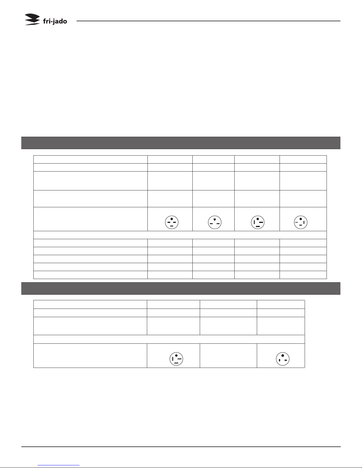
TECHNICAL DATA U.S. STANDARD MODELS
Type STG 5 STW 5 STG 7 STW7
Power 6500W 2800W 10200W 3500W
Fuses needed with power connection
208 V, 3 ~ 60 Hz (3 phases without
zero)
Fuses needed with power connection
208 V, 1N ~ 60 Hz (1 phase with zero)
Standard plug from factory NEMA 15-30P NEMA 6-15P NEMA 15-50P NEMA 15-20P
Stacked STG/STW cabinets: each cabinet comes with separate power cord!!
Net weight 269 lbs. 220 lbs. 399 lbs. 331 lbs.
Gross weight 350 lbs. 269 lbs. 478 lbs. 363 lbs.
Height 34 1/4” 34 1/4” 40 3/8” 40 3/8”
Width 32 9/16” 32 9/16” 38 13/16” 38 13/16”
Depth 25 5/8” 25 5/8” 33 1/2” 33 1/2”
3x 20 A - 3x 35 A 3x 20 A
_
G
Z
X
Y
1x 15 A
G
_ _
G
Z
X
Y
G
Z
X
Y
TECHNICAL DATA U.S. SPECIAL MODELS
Type STG 5 STG 7 STW7
Power 6100W 9500W 3500W
Fuses needed with power connection
208 V, 1N ~ 60 Hz (1 phase with zero)
Stacked STG/STW cabinets: each cabinet comes with separate power cord!!
Standard plug from factory NEMA 6-50P n/a ( fixed wiring ) NEMA 6-20P
Tools
• Standardsetoftools.
• Metricwrenches,socketsandhexsocketkeywrenches.
• Multi-meterandACcurrentclampmeter.
• Temperaturetester.
• Insulation value tester (Megger).
• FieldServiceGroundingKit.
Page 6
1x 35 A 1x 60 A 1x 20 A
G
Z
X
Y
Service Manual STG5/7 STW5/7 form 9123647 rev. 03/2014
G
PROGRAMMING INSTRUCTIONS
PROGRAMMING INSTRUCTIONS FOR THE STG5 / STG7 AND STW5 / STW7
DISPLAY AND KEYS
Time Display
Temperature Display
Program indicators
Program keys
Buzzer key
Probe key
Temperature key
Up-Down key
Time key
SETTING THE STW
8888888410 0030
Temperature hold indicator
Second step indicator
First step indicator
Start / Stop
Rotor key
Time of day
Program end
Temperature hold process
Second cooking step
First cooking step
SETTING THE STG
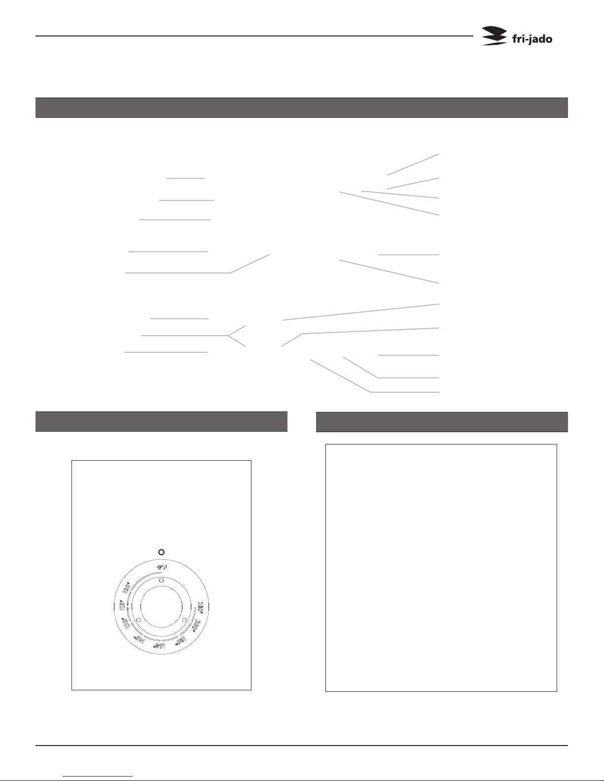
THERMOMETER
THERMOSTAT DIAL
Turn thermostatdial to desired temperature
Service Manual STG5/7 STW5/7 form 9123647 rev. 03/2014
When the main switch is turned to “1” the
display lights up and the rotisserie is ON.
Page 7

PROGRAMMING INSTRUCTIONS
SETTING ACTUAL TIME 15 PROGRAMS
888410 88881040
ENTERING A PROGRAM
888p01 8888prog
Press and hold Time of
day key
Press Up or Down key
Release Time of day key
Select Program number
Press both Up and Down
keys during 2 seconds
After the unit is swit-
888p01 888815pr
ched-on the time display
indicates: 15PR
Key 1:
1x = program 01
2x = program 06
3x = program 11
Key 2:
1x = program 02
2x = program 07
3x = program 12
FIRST COOKING STEP (TIME)
Press Cooking process
888000 88880040
key
Cooking symbol lights
up
FIRST COOKING STEP (TEMPERATURE)
Press and hold the Tem-
888410 88880040 888000 88880030
perature key
Press Up or Down key
SECOND COOKING STEP (TIME)
Press and hold the Time
key
Press Up or Down key
Press Grilling process key
Grilling symbol lights up
Press and hold the Time
key
Press Up or Down key
Page 8
Service Manual STG5/7 STW5/7 form 9123647 rev. 03/2014

PROGRAMMING INSTRUCTIONS
SECOND COOKING STEP (TEMPERATURE) TEMPERATURE HOLD
888355 88880030
LOADING PROGRAM
888185 88880000
Press and hold Tempera-
ture key
Press Up or Down key
Press program number
to load pre-set values
Press Temperature Hold
888185 88880000
process key
Temperature Hold symbol lights up
Press and hold the Temperature key
Press Up or Down key
PROGRAM START & LOADING
Press Start / Stop key
888000 88880040
On indicator lights up
Press Rotor key to start
turning the rotor
OPTIONAL SETTINGS FOR THE STG5 AND STG7
INTERRUPTING ACTIVE PROGRAM
Press Rotor key
888380 88880046
Heaters and front lamp
switch off
Rotor stops
On indicator is blinking
Process time in hold
Press Rotor key again to
stop
Load the rotisserie with
products
SET ADDITIONAL BUZZER SIGNAL
Select a pre-defined
888p01 88881055
program
Press and hold Buzzer
key
Press Down key
Service Manual STG5/7 STW5/7 form 9123647 rev. 03/2014
Page 9

PROGRAMMING INSTRUCTIONS
SET PROGRAM END TIME DISPLAY SET TIME & TEMPERATURE
Select a pre-defined
888p01 88881030 888410 88880040
ADJUSTING ACTIVE PROGRAM
program
Press and hold the Pro-
gram end key
Press Up key
PREHEAT INDICATION
Press and hold Temperature or Time key
888390 88880035 888prh 88880059
Adjust temperature or
time with Up or Down
key
Select a pre-defined
program
Press Cooking, Grilling
or Temperature hold key
No time indictaion for
Temperature hold
Visible during process or
program selection
Under 40°C (104°F) the
display shows PRH
TEMPERATURE PROBE (OPTIONAL)
Press the Rotor key
888185 88880046
Page 10
Insert the probe in the
meat up to the core
Press Temperature sen-
sor key; after 20 seconds
the temperature reading
swtiches off
INDICATIONS DURING PROCESS
• Processindicatorsshowsactualprocess
after completion indicator switches off
• Timedisplayshowsremainingprogram
time which is the sum of the remaining
cooking and grilling time
• Temperaturedisplayindicatesactual
temperature in the grill. Under 40°C
(104°F) the display shows PRH (preheat)
• Whenremainingtimereaches0,the
process indicators and the On-indicator
switches off
Service Manual STG5/7 STW5/7 form 9123647 rev. 03/2014
REMOVAL AND REPLACEMENT OF PARTS
REMOVAL AND REPLACEMENT OF PARTS FOR THE STG5 AND STG7
WARNING: Disconnect the electrical power to the machine at
the main circuit box. Place a tag on the circuit box indicating
the circuit is being serviced.
RIGHT OR LEFT SIDE PANEL
1. Remove the screws that secure the panel
to the frame.
2. Remove the panel.
3. Reverse the procedure to install.
TOP COVER
1. Remove the left side panel according
prior procedure.
2. Remove the screws securing both large
and small top covers.
3. Remove the top cover. (Lift at left side and
remove to the left).
4. Reverse the procedure to install.
Note: STG 5 has an optional special top cover
for access to the circulation blower. Standard
no cover for the blower.
Service Manual STG5/7 STW5/7 form 9123647 rev. 03/2014
Page 11
REMOVAL AND REPLACEMENT OF PARTS
KNOB
1. Remove cover plate on the knob with a
small screw driver.
2. Loosen the srew inside the knob.
3. Remove the knob with ring.
4. Reverse the procedure to install.
Note: check that the ring behind the knob is
in the right position and runs free from the
panel.
OPERATING PANEL
1. Remove the right side panel according
prior procedure.
2. Remove the knob according prior procedure.
3. Remove the screw that secures the panel.
4. Remove the 2 bolts on the backside of the
operating panel (top and bottom side,
only for the STG 7).
5. Remove the screws that secure the meat
probe holder and remove the holder (if
supplied).
6. Remove the flatcable on the power section.
7. Remove the clip on the back, top left side
that secures panel and frame.
8. Remove the instrument panel.
9. Reverse the procedure to install.
Page 12
Service Manual STG5/7 STW5/7 form 9123647 rev. 03/2014
REMOVAL AND REPLACEMENT OF PARTS
ELECTRIC PANEL
1. Remove the operating panel according
prior procedure.
2. Remove on the front side the screws that
secure the panel.
3. Remove on the inside bottom of the electric panel the bolt and nuts.
4. Disconnect the wiring.
5. Slide the electrical panel backwards.
6. Reverse the procedure to install.
DISPLAY
1. Remove the right side panel according
2. Disconnect the flatcable on the display.
3. Remove the clip on the back, top left side
4. Remove the nuts and washers on the
5. Remove the nuts and plastic rings that
6. Reverse the procedure to install.
prior procedure.
that secures panel and frame.
backside of the display and remove the
metal cover.
secure the board and remove the board.
Do not forget to disconnect the blue connector on the board.
Service Manual STG5/7 STW5/7 form 9123647 rev. 03/2014
Page 13
REMOVAL AND REPLACEMENT OF PARTS
PANEL AND KEYPAD ASSEMBLY
1. Remove the operating panel according
prior procedure.
2. Remove the display according prior procedure.
3. Remove the nuts that secure the keypad
and remove the keypad.
4. Reverse the procedure to install.
NAMEPANEL
1. Remove the operating panel according
JP3 & JP4
prior procedure.
2. Remove the 4 nuts that secure the panel
and remove the panel.
3. Reverse the procedure to install.
POWER AND I/O BOARD
1. Remove the right side panel according
prior procedure.
2. Disconnect wiring and flatcable on the
board.
3. Remove the board from the clips by pres-
Page 14
sing the clips together.
4. Reverse the procedure to install.
Note: When installing a new board, ensure
that JP3 and JP4 on new board are set the
same as on the old board.
Service Manual STG5/7 STW5/7 form 9123647 rev. 03/2014
REMOVAL AND REPLACEMENT OF PARTS
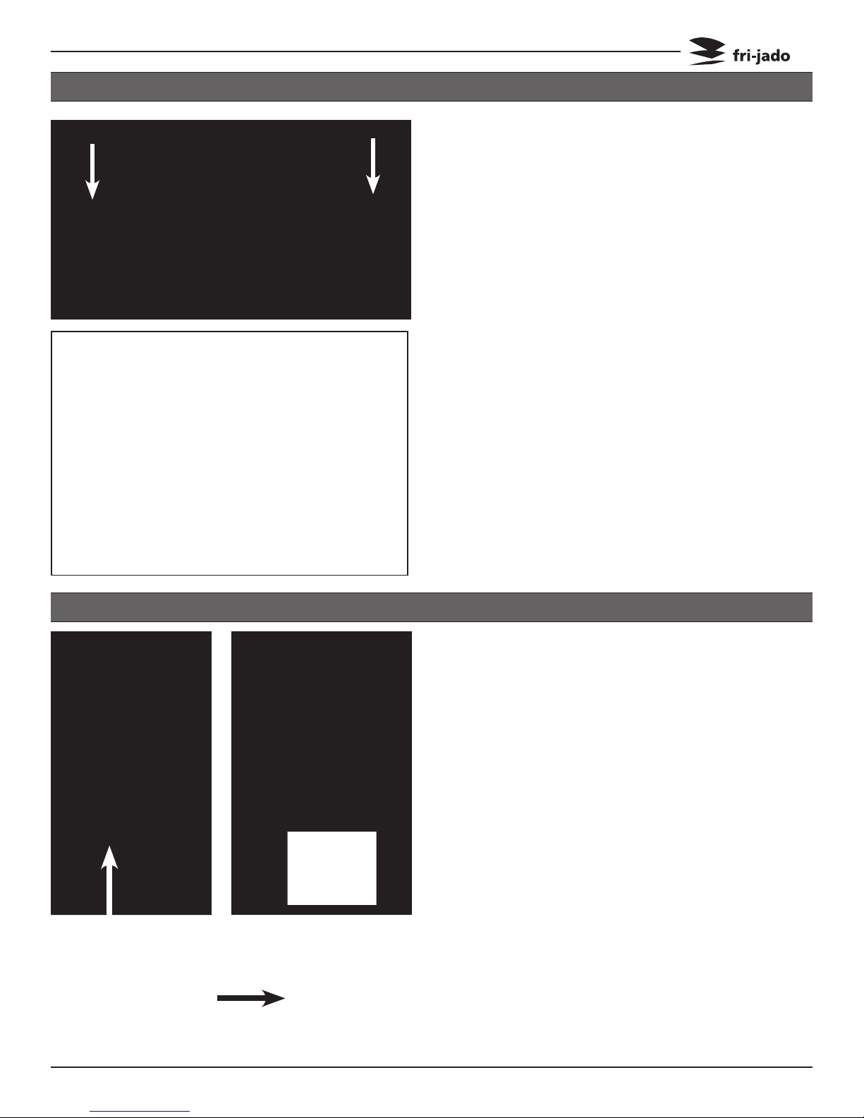
QUARTZ LAMP
Caution: Do not touch the glass with your hands.
The moisture from your hands could affect the
live span of the lamp. This moisture can be removed with alcohol while the lamp is cold.
Note: Use a clean rag or paper towel to replace
the lamp.
1. Remove the insulators of the lamp, see arrow.
2. Remove the bolt from each end of the lamp
and remove the lamp.
3. Install the lamp with the painted side towards
the top of the oven. Hold the metal with your
hand when tightening the bolts to prevent
the metal from twisting and damaging the
lamp.
4. Tighten the insulators evenly to prevent
damage.
MAIN SWITCH
1. Remove the instrument panel according
prior procedure.
2. Loosen the screws on the electric panel that
secure the switch.
3. Remove the switch and disconnect the wiring.
4. Reverse the procedure to install.
Note: The main switch until serial nuber
Main switch till serial
number 100050804
New main switch
Service Manual STG5/7 STW5/7 form 9123647 rev. 03/2014
100050804 is different than the new
main switch.
Page 15
REMOVAL AND REPLACEMENT OF PARTS
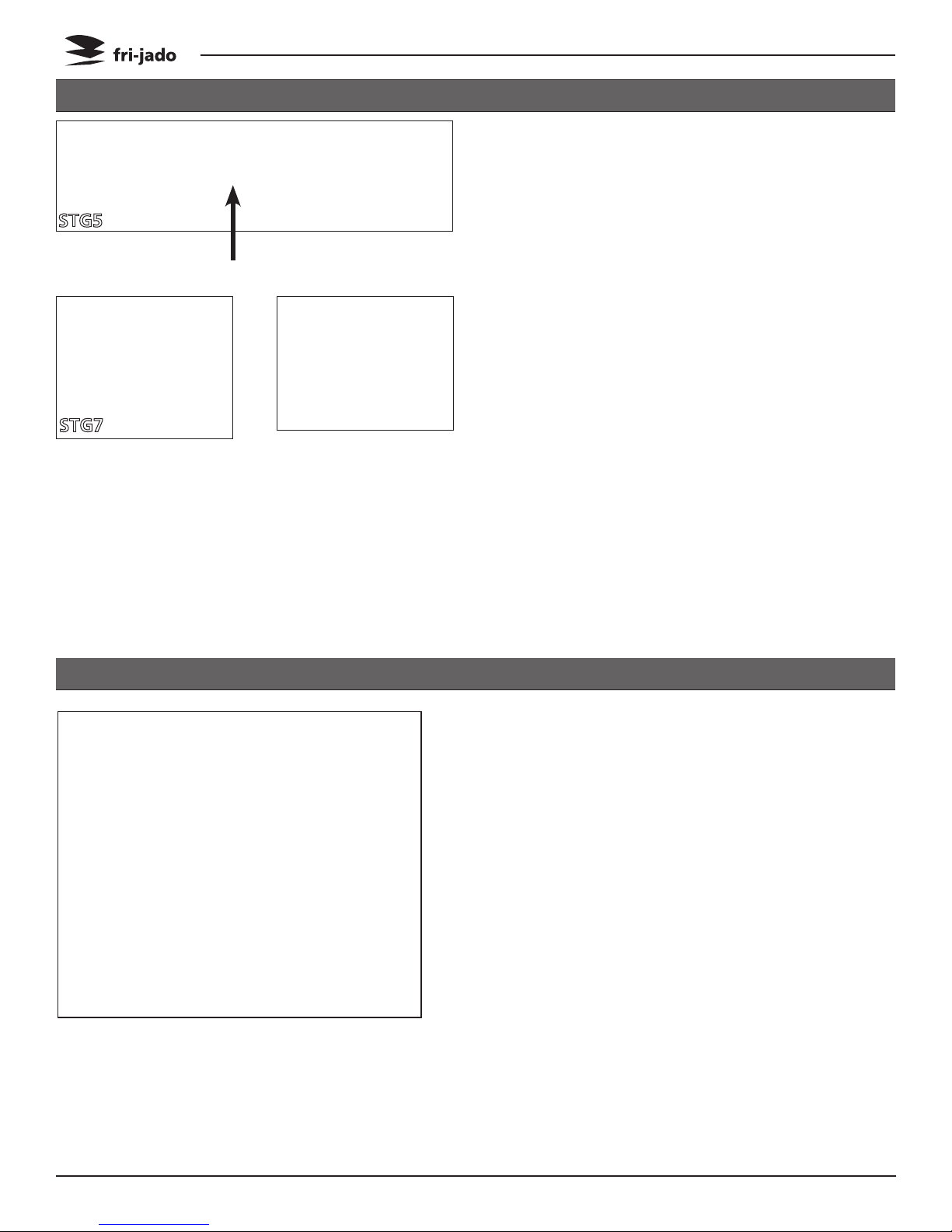
HIGH LIMIT THERMOSTAT
1. Remove the right side panel according prior
procedure.
2. Remove the suction and fan plate on the cei-
STG5
STG7
ling on the inside of the oven.
3. (STG 5 only) Remove the nut on the clamp
(see black arrow) and slide clamp towards
yourself. Loosen the screw in the clamp that
secures the probe and remove the probe.
4. (STG 7 only) Remove the thermostat-probe
from the clip in the oven and guide it outside
through the opening in the side wall.
5. Remove the screws on the electric panel that
secure the thermostat (see white arrow).
6. Remove the thermostat and disconnect the
wiring.
7. Reverse the procedure to install.
Note: Set the new high limit thermostat to its
maximum position.
CONTACTOR
1. Remove the right side panel according prior
procedure.
2. Disconnect the lead wires to the switch.
3. Push the locking tab down with a screw
driver and lift the contactor out to remove
it from the mounting bracket.
4. Reverse the procedure to install.
Page 16
Service Manual STG5/7 STW5/7 form 9123647 rev. 03/2014
REMOVAL AND REPLACEMENT OF PARTS
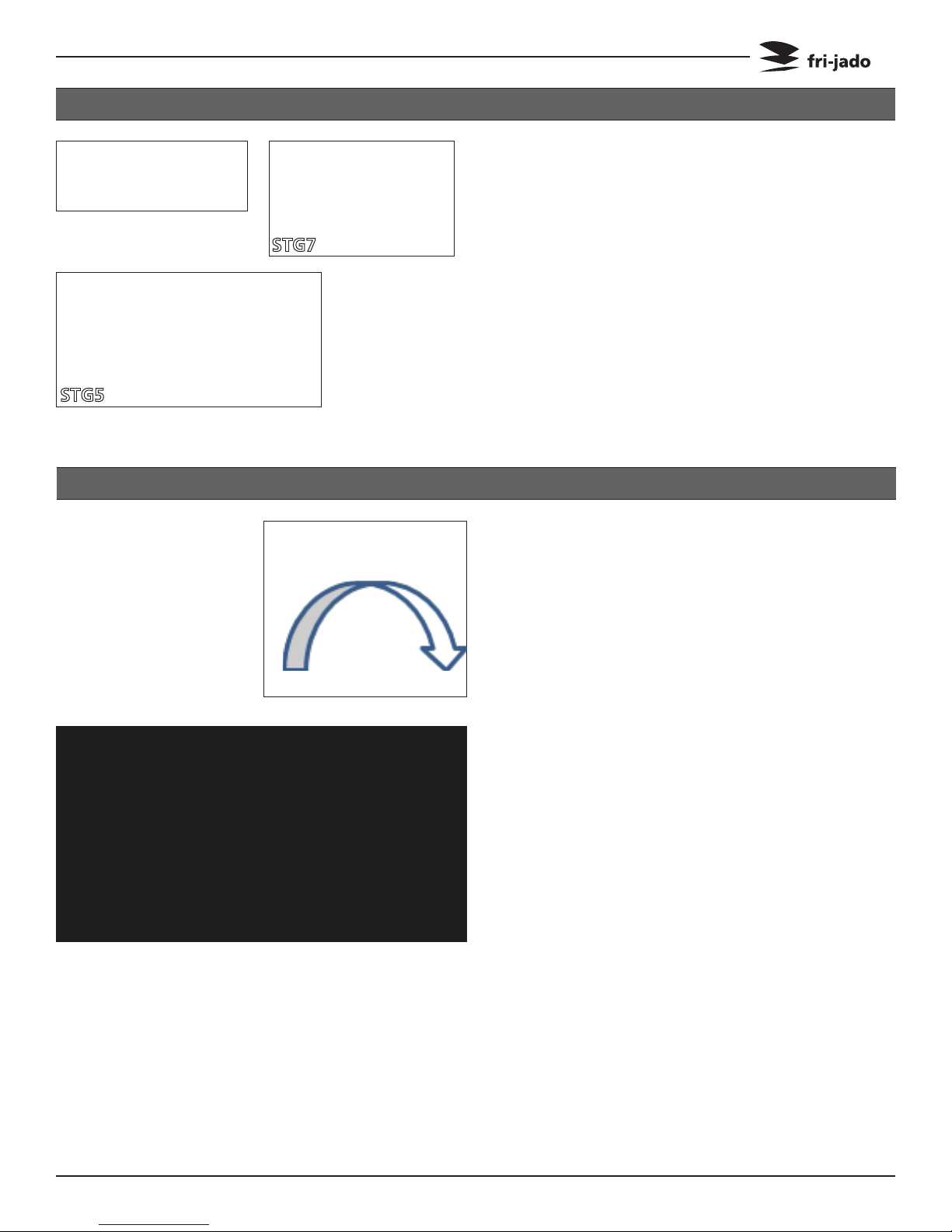
HEATING ELEMENT
1. Remove the rotor discs, right side panel,
suction and fan plate on the ceiling according prior procedures.
STG5
STG7
2. Disconnect the wiring from the element.
3. Remove the mounting nut.
4. Remove the element from the mounting
clip and pull it from the wall.
5. Reverse the procedure to install.
BLOWER MOTOR
1. Remove the right side panel and the top
cover according to prior procedures.
2. Remove the rotor discs, suction and fan
plate on the ceiling inside the oven.
3. Remove the wing nut on the fan blade and
remove fan blade. (Left handed threads)
4. Disconnect wiring of the motor.
5. Remove the screws that secure the motor
and remove the motor.
6. Reverse the procedure to install.
Note: The blower(s) are equipped with a capacitor of 1,5 uF. Check the direction of rotation
of the motor (clockwise, see arrow) and change the wiring if necessary.
Service Manual STG5/7 STW5/7 form 9123647 rev. 03/2014
Page 17
REMOVAL AND REPLACEMENT OF PARTS
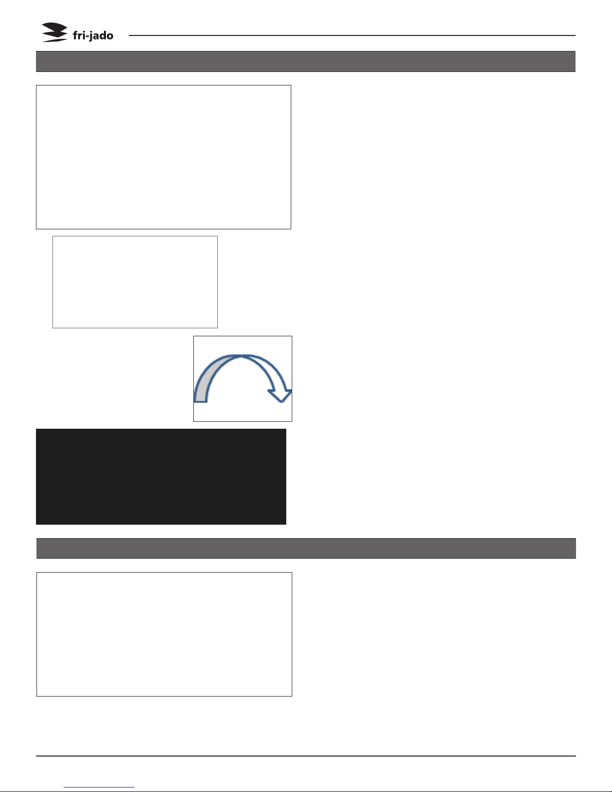
BLOWER MOTOR BOTTOM ROTISSERIE (STACKED STG)
1. Remove the right side panel according prior
procedures.
2. Remove the rotor discs, suction and fan
plate on the ceiling inside the bottom oven.
3. Remove the wing nut on the fan blade
and remove the fan blade. (Left handed
threads).
4. Remove fat drawer from upper oven.
5. Remove the bolts that secure the intermediate plate and remove this plate.
6. Remove the drip trays from the upper oven.
7. Remove the bolts that secure the top plate
(STG 5 must have a special top cover!) and
remove the top plate.
8. Disconnect wiring of the motor.
9. Remove the screws that secure the motor
and remove the motor.
10. Reverse the procedure to install.
Note: The blowers are equipped with a capacitor of 1,5 uF. Check the direction of rotation of
the motor (clockwise, see arrow) and change
the wiring if necessary.
PT500 SENSOR
1. Remove the right side panel according to
prior procedure.
Page 18
2. Disconnect the wiring of the sensor.
3. Remove the screw that secures the sensor
and remove the sensor.
4. Reverse the procedure to install.
Note: The wiring cable is an insulated cable
with a earthing screen.
Service Manual STG5/7 STW5/7 form 9123647 rev. 03/2014
REMOVAL AND REPLACEMENT OF PARTS
DRIVE MOTOR
1. Remove the right side panel and rotor discs
according prior procedure.
2. Disconnect the wiring of the motor. Check
where the wire, marked A is connected.
3. Remove the screws that secure the fan cover
and remove the cover.
4. Note down how far the drive arm or drive
block sticks out from the inner wall (see
white or black arrow).
5. (STG 5 only) Remove the nuts that secure the
motor and remove the motor.
6. (STG 7 only) Set the drive arm in a position
vertical downwards. This can be done manually or by turning the fan blade by hand.
7. Mark the position of the motor support with
a marker.
8. Remove the bolts that secure the motor and
the nuts that secure the motor support and
remove the motor.
9. Check the white Teflon ring. Replace this if
necessary.
10. Check the position of the red gasket between motor support and the side wall. Replace this if necessary.
11. Install the fan blade on the new motor.
12. Reverse the procedure to install.
Note: Always make a test run of 15 minutes on
maximum temperature to insure the motor is
well mounted and adjusted and turns parallel
to the side wall.
Service Manual STG5/7 STW5/7 form 9123647 rev. 03/2014
Page 19
REMOVAL AND REPLACEMENT OF PARTS
DOOR ADJUSTMENT (LEFT SIDE)
1. Remove the left side panel according prior
procedure.
2. Loosen the nuts (A) of the upper hinge. The
B
A
C
A
DOOR INSIDE
door must be closed.
3. Loosen the locknut (B) and adjust the bolt
(C) in or out to adjust the door.
4. Tighten the nuts of the hinge and mount
the left-hand panel.
1. Separate the inside door from the outside
door.
2. Lift the inside door upward out of the hinges.
3. Place the new door in the hinges.
4. Close the inside door on the outside door.
Note: Tightening of nuts max. 6 Nm. or
4.5 lbf.ft
Page 20
Service Manual STG5/7 STW5/7 form 9123647 rev. 03/2014

REMOVAL AND REPLACEMENT OF PARTS
DOOR OUTSIDE
1. Lift the inner door out of the hinges and lay
this aside.
2. Remove the left side panel according prior
procedure.
3. Remove the 2 nuts behind the upper hinge
and loosen the locknut according prior procedure. The door must be closed.
4. Hold the door on both sides and move this
towards yourself, before lifting it out of the
hinge on the bottom side. See to it that the
washers stay on the hinge.
Also remove the top hinge.
5. Place the top hinge on the new door.
6. Place the new door on the hinge on the
bottom side and push the 2 studs on the top
hinge through the openings on the top side
and screw the nuts on it .
7. Adjust the door according prior procedure.
Note: Tightening of nuts max. 6 Nm. or
4.5 lbf.ft
Service Manual STG5/7 STW5/7 form 9123647 rev. 03/2014
Page 21
 Loading...