

Fri-Jado BC 5-p, BB 3-e, BB 3-p, BB 5-e Installation Manual
Installation Manual Bake Basic form 9123764 rev. 03/2017WWW.FRIJADO.COM
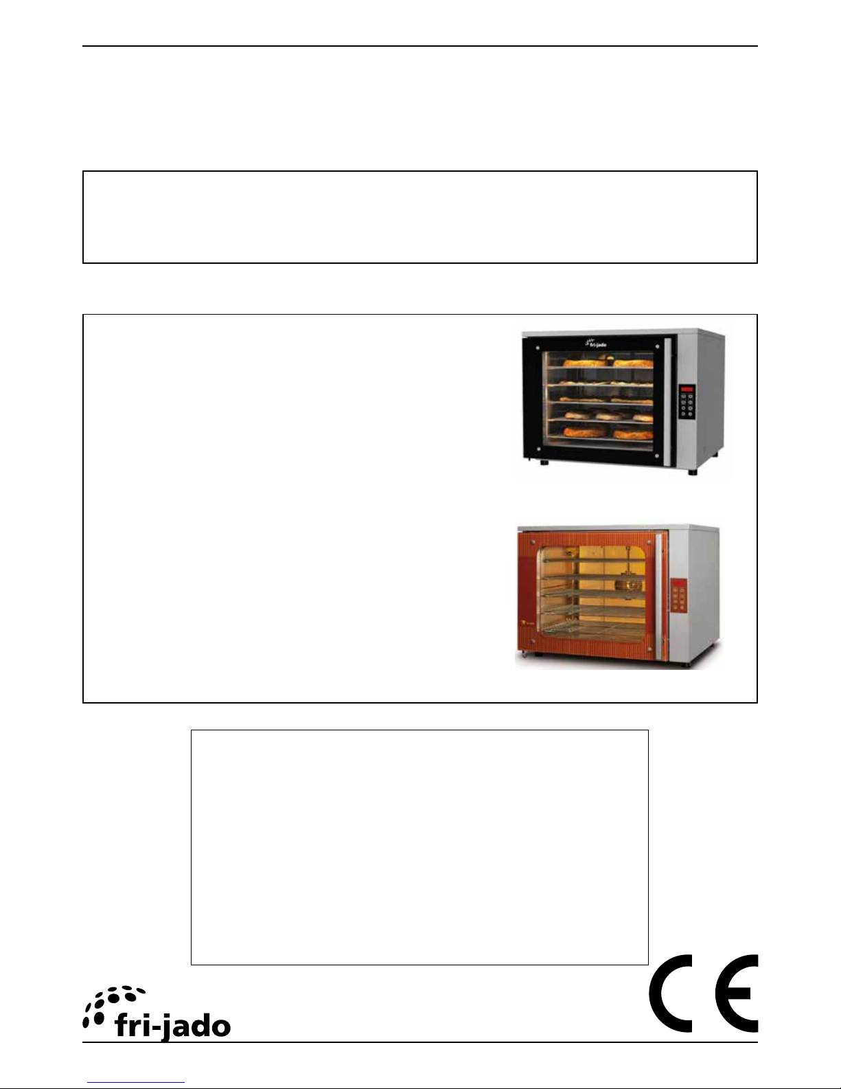
Bake Convection & Bake Basic
- NOTICE -
This manual is prepared for the use of trained Service Technicians and should
not be used by those not properly qualified. If you have attended a training
for this product, you may be qualified to perform all the procedures in this
manual.
This manual is not intended to be all encompassing. If you have not attended a
training for this product, you should read, in its entirety, the repair procedure
you wish to perform to determine if you have the necessary tools, instru-
ments and skills required to perform the procedure. Procedures for which you
do not have the necessary tools, instruments and skills should be performed
by a trained technician.
Reproduction or other use of this Manual, without the express written consent of
Fri-Jado, is prohibited.
INSTALLATION MANUAL
MODELS
BC 5-p
BB 3-e
BB 3-p
BB 5-e
BB 5-p
Model BB 5-p
Model BC 5-p

Installation Manual Bake Basic form 9123764 rev. 03/2017
Page 2
TABLE OF CONTENTS
EMPTY PAGE

Installation Manual Bake Basic form 9123764 rev. 03/2017
Page 3
TABLE OF CONTENTS
INDEX
Index .......................................................................................................................................................... 3
General technical data .............................................................................................................................. 4
Technical Data ....................................................................................................................................... 4
Installation procedures ............................................................................................................................. 6
Unpacking and removing the unit from the pallet ............................................................................. 6
Location .................................................................................................................................................. 6
Electrical supply ..................................................................................................................................... 6
Test run ................................................................................................................................................... 6
Instructions for operators ...................................................................................................................... 6
Installation of stand-alone units .............................................................................................................. 7
BB 3-p drop in or mounted on skirting bracket .................................................................................. 7
BB 3-p drop in (with downfalling door ) ......................................................................................... 8
BB 5-p drop in or mounted on skirting bracket .................................................................................. 9
BC & BB “footprint” and air-grids .................................................................................................... 10
Underframes and stacking ..................................................................................................................... 11
Assembly instructions underframe 2x9 tray ....................................................................................... 11
Assembly instructions underframe 2x5 tray ....................................................................................... 13
Stacking of Bake Basic units with kit 3709535. ................................................................................. 15
Installation examples of units on underframe ..................................................................................... 16
BB 3-p on underframe (2x9) ................................................................................................................ 16
BB 3-p + 3-P on underframe (2x9) with hood ................................................................................... 17
BB 3-p + 3-P on underframe (2x5) with hood ................................................................................... 18
BC 5-P or BB 5-p on underframe (2x9) ................................................................................................ 19
BC or BB 5-p + 5-P on underframe (2x5) with hood ......................................................................... 20
BB 3-p + 5-P on underframe (2x5) with hood .................................................................................... 21
BC 5-p + 5-P on underframe 3709550 with hood ............................................................................. 22
BB 3-p with down faling door on underframe (2x9) ....................................................................... 23
BB 3-p + 3-P with downfaling door on underframe (2x5) .............................................................. 24
GENERAL TECHNICAL DATA
Page 4
Installation Manual Bake Basic form 9123764 rev. 03/2017
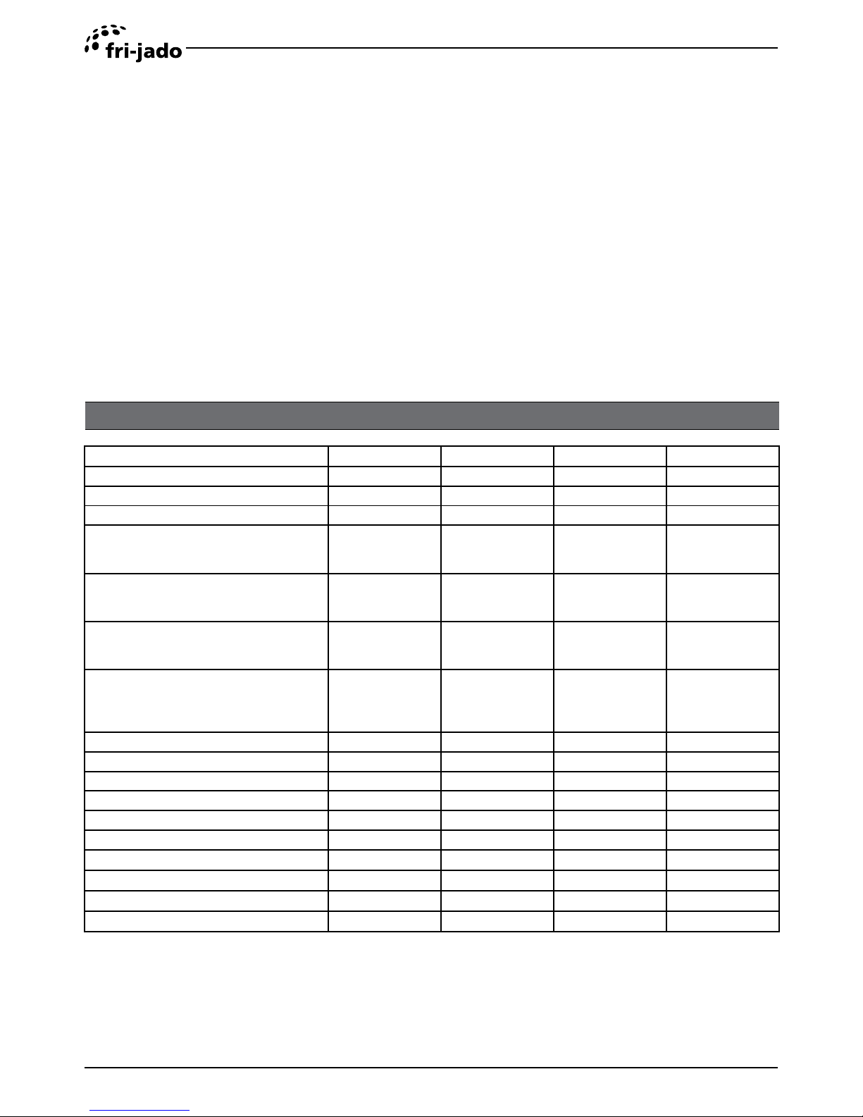
TECHNICAL DATA
STANDARD MODELS BS 3-e BB 3-p BB 5-e BB 5-p
Power 2840W 2840W 5760W 5760W
Voltage 230V 1~ 50/60Hz 230V 1~ 50/60Hz 400V 3N~ 50Hz 400V 3N~ 50Hz
Max. rated current 13A 13A 9,5 9,5
Fuses needed with power connection400V 3N~50…60Hz ( 3 phases with
neutral)
---------- ----------- 3x10A 3x 10A
Fuses needed with power connection
230V 3~50…60Hz (3 Phases without
neutral)
---------- ---------- 3x 20A 3x 20A
Fuses needed with power connection
230V 1~50…60Hz (1 Phases)
13A 13A 25A
Note: mount
other mains cable
25A
Note: mount
other mains cable
Standard plug from factory
(according to IEC 60309 and CEE-form)
1x EURO Plug
1x UK Plug, 13A
1x EURO Plug
1x UK Plug, 13A
16A 3P+N+E
5 pole CEEFORM
(according to IEC
60309)
16A 3P+N+E
5 pole CEEFORM
(according to IEC
60309)
Default cable 3x2,5 mm² 2mtr 3x2,5 mm² 2mtr 5x2,5 mm² 2,5mtr 5x2,5 mm² 2,5mtr
Gross weight 77 kg 77 kg 92 kg 92 kg
Net weight 63 kg 63 kg 75 kg 75 kg
Hight 460 mm 460 mm 650 mm 650 mm
Width 840 mm 840 mm 840 mm 840 mm
Depth 787 mm 787 mm 787 mm 787 mm
Waterinlet connection n/a ¾” n/a ¾”
Fume outlet 1 pc of 1” 2 pc of 1” 1 pc of 1” 2 pc of 1”
GENERAL TECHNICAL DATA
This manual covers the Bake Convection and Bake Basic series bake-off ovens.
• BC 5-p Bake-off oven with 5 levels, programmable
• BB 3-e Bake-off oven with 3 levels
• BB 3-p Bake-off oven with 3 levels, programmable
• BB 5-e Bake-off oven with 5 levels
• BB 5-p Bake-off oven with 5 levels, programmable
All of the information, illustrations and specifications contained in this manual are based on the
latest product information available at the time of printing.

GENERAL TECHNICAL DATA
Page 5
Installation Manual Bake Basic form 9123764 rev. 03/2017
• Unpacking of the unit.
• Remove the pallet under the unit with the help of a fork lift or at least 3 people.
• Put the unit on his location.
• Check if there is enough free space around the unit (see label.).
• Check the electrical supply.
• Check all settings and make a test run with all functions switched on.
• Give instructions to the operator.
UNPACKING AND REMOVING THE UNIT FROM THE PALLET
Immediately after unpacking the oven, check for possible shipping damage. If the oven is found to be damaged, save the
packaging material (make pictures) and contact the carrier within 15 days of delivery. Remove the pallet under the unit with
the help of a fork lift or at least 3 people.
LOCATION
The oven must be installed on a level and flat surface. The installation location must allow adequate clearances for servicing
and for proper operation.
Make sure that a free airflow for airgrids is ensured. See also chapter “Bake Basic “footprint”and airgrids.
ELECTRICAL SUPPLY
Prior to installation, test the electrical service to assure that it agrees with the specifications on the machine data plate loca-
ted on the backpanel. The connecting cable for the unit must be equipped with an approved plug connection. If use is to be
made of a permanent connection, the connecting cable must be connected to a manual on/off switch that is installed near
the unit in a clear visible way.
TEST RUN
Operate the Bake Basic oven at a temperature setting of 250°C, for 30 minutes. Within these 30 minutes the bakestar oven
could release some unpleasant odour as a result of the first heating of some metal parts
INSTRUCTIONS FOR OPERATORS
After installation of the oven, the operator of the unit has to be instructed.
The instruction has to cover the following subjects:
• Programming and options.
• Working of the unit.
• Free space of unit for servicing and for proper operation.
• Run through the user manual.
• Cleaning of the unit.
• How to react for obtaining information or making service calls.
INSTALLATION PROCEDURES
INSTALLATION PROCEDURES
Page 6
Installation Manual Bake Basic form 9123764 rev. 03/2017
PLACING AND CONNECTING
Page 7
Installation Manual Bake Basic form 9123764 rev. 03/2017
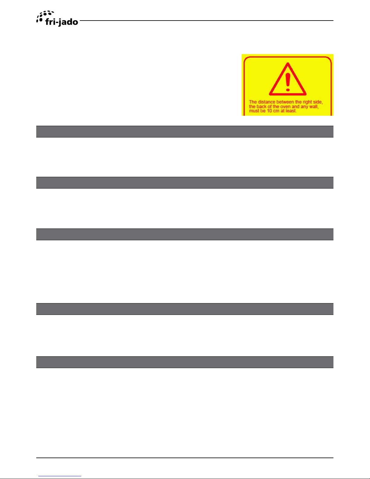
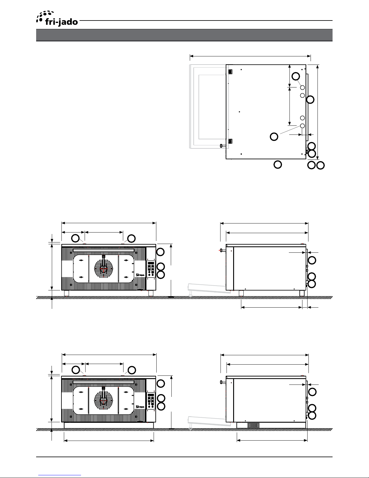
DESCRIPTION OF THE LABELS
1 Power cable 3 e and p models, 2mtr.
5 e and p models, 2,5 mtr.
2 Watersupply inlet “G”¾”
Tube length 1,5 mtr.
4 Fume outlet oven, 25mm (all models)
4p Fume outlet oven, 25mm (only p models)
5 Exhaust pipe hood, 180mm
7 Space between the oven and a wall, 100mm
8 Location for wall socket (in conformity with CE)
9 Location for aired tap “G” ¾ inch (only p models)
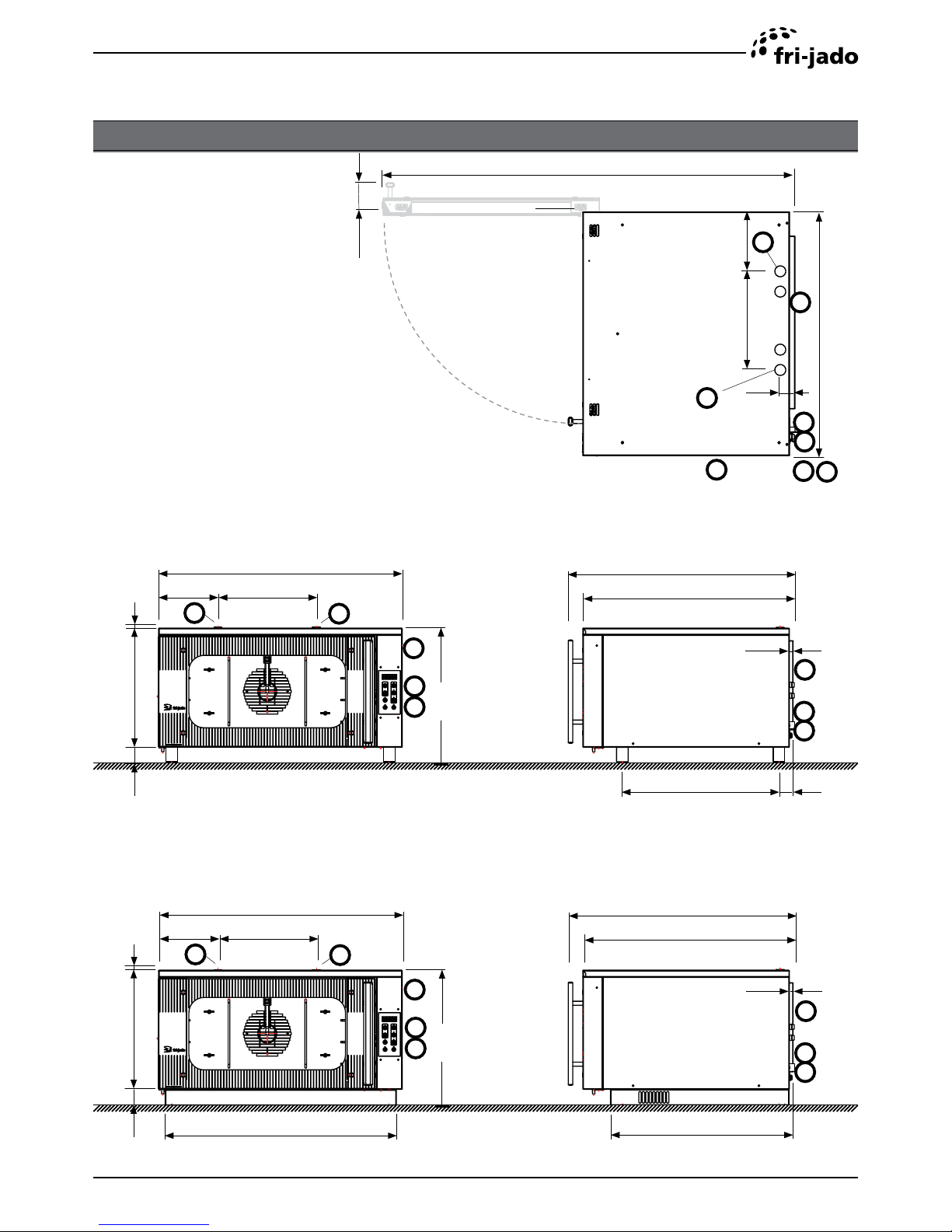
BB 3-P DROP IN OR MOUNTED ON SKIRTING BRACKET
Mounted on skirting bracket
INSTALLATION OF STAND-ALONE UNITS
946
340
205
47
8
9
1
2
4p
4
7
7
1415
100
460
840
205 340
727
777
1
2
8
9
7
7
4p
4
465
840
205 340
727
777
1
2
8
9
7
7
4p
4
798
631
15
15
540
50
410
55
5
410
50
5
PLACING AND CONNECTING
Page 8
Installation Manual Bake Basic form 9123764 rev. 03/2017
DESCRIPTION OF THE LABELS
1 Power cable 3 e and p models, 2mtr.
5 e and p models, 2,5 mtr.
2 Watersupply inlet “G”¾”
Tube length 1,5 mtr.
4 Fume outlet oven, 25mm (all models)
4p Fume outlet oven, 25mm (only p models)
5 Exhaust pipe hood, 180mm
7 Space between the oven and a wall, 100mm
8 Location for wall socket (in conformity with CE)
9 Location for aired tap “G” ¾ inch (only p models)
Mounted on skirting bracket
BB 3-P DROP IN (WITH DOWNFALLING DOOR )
946
340
205
47
8
9
1
2
4p
4
7
7
460
840
205 340
727
777
1
2
8
9
7
7
4p
4
465
840
205 340
727
777
1
2
8
9
7
7
4p
4
1060
798
631
15
15
540
50
410
55
5
410
50
5
 Loading...