

Page 1

n r
MANTECATORI ORIZZONTALI ELETTRONICI
ELECTRONIC HORIZONTAL BATCH FREEZER
MANUALE D’USO
E
MANUTENZIONE
OPERATING INSTRUCTION
l-ris
AND MAINTENANCE
Serie-Series-Serie-Serie
C119 06
C122 03
‘‘P - I
I
w
I t
X f l y l o r d F ’ «iKKw»«»’
^ ,ce cream machines
Azienda Certificata
UNI EN ISO 9001:2000
Numero Certifrcato
50 100 5650
Page 2
• T W L O R S^f/NGommr
■ » ■ teo era n a tiM C h in B B
IM PORTANTE
Vi raccomandiamo di leggere attentamente e interamente questo manuale prima di
utilizzare la Vostra macchina.
Nel Vostro proprio interesse fate attenzione in particolare alle avvertenze
contrassegnate nel modo seguente:
A p e r i c o l d A
II mancato rispetto di questo segnale causa rischi molto gravi per la salute, morte,
danni permanent! a medio o a lungo termine.
A avvertenzaA
II mancato rispetto di questo segnale puo causare rischi molto gravi per la salute,
morte, danni permanent! a medio o a lungo termine.
A c a u t e l a A
II mancato rispetto di questo segnale puo causare infortuni o danni alia macchina.
A attenzidn eA
Osservare queste avvertenze per ottenere il buon funzionamento della macchina
e/o la corretta manutenzione.
\L /
^-SUG GERIM ENTDA^ -
Solo osservando attentamente queste avvertenze e possibile ottenere dalla
macchina le massime prestazioni possibili.
1 - ITALIANO
FRGMTMEB2DGT2916000
Page 3
■ * v-T (r» cRnttunachnns
Ci congratuliamo con Voi per aver scelto di acquistare una macchina TAYLOR.
II seguente manuale, fornito a corredo della macchina, e da considerarsi parte integrante
ed essenziale della stessa e dovra essere consegnato aH’utilizzatore finale. Prima di
eseguire qualsiasi operazione si raccomanda di studiare attentamente le istruzioni in esso
contenute poiche solo un’attenta lettura vi permettera di ottenere dalla Vostra macchina il
massimo delle prestazioni. Nelle pagine seguenti sono presenti tutte le indicazioni
necessarie per eseguire correttamente le operazioni di installazione, funzionamento,
regolazione e manutenzione ordinaria. La TAYLOR si riserva il diritto di apportare senza
preavviso le modifiche che riterra necessarie per migliorare il proprio prodotto o il proprio
manuale tecnico inserendo le variant! nelle successive edizioni.
E vietata la riproduzione totale e/o parziale, I’adattamento o la traduzione del presente
manuale senza previa autorizzazione scritta da parte di TAYLOR S.r.l.
La macchina e coperta da garanzia secondo le condizioni illustrate sulla “CARTOLINA DI
GARANZIA “ a corredo che deve essere debitamente compilata e restituita a:
FRIGOMAT s.r.l., via 1° Maggio, 28 26862 GUARDAMIGLIO (LODI) - ITALIA
Perfavore scrivete nel campo sottostante il numero di matricola della Vostra macchina
Numero matricola
Timbro del concessionario
ITALIANO - 2
Page 4
l" D S y L O R ‘®y S ^ffiK io m a T
INDICE
1. TRASPORTO, MOVIMENTAZIONE E IMMAGAZZINAMENTO
1.1 Ispezione preliminare ........................................................ 4
1.2 Dimensioni e pesi delle macchine imballate
1.3 Indicazioni per la messa fuori servizio
2. MARCATURA E SEGNI GRAFICI ...............................
3. NORME GENERALI Dl SICUREZZA
4. INSTALLAZIONE
4.1 Impieghi .........................................
4.2 Limiti di impiego ............................................................ 8
4.3 Rumorosita ....................................................
4.4 Dotazione macchina ............................................................ 8
4.5 Messa in funzione
5. DISPOSITIVI Dl SICUREZZA 12
6. FUNZIONAMENTO 13
6.1 Macchina 13
6.2 Comandi 14
,6.3 Produzione gelato e granita
6.3.1 Cicio automatico
6.3.2 Cicio automatico hard
6.3.3 Cicio semiautomatico con controllo consistenza
6.3.4 Cicio semiautomatico con controllo tempo
6.3.5 Programme granita ............................................................ 23
6.3.6 Programme granita al caffe................................................ 25
6.4 Estrazione . 27
7. MANUTENZIONE 28
7.1 Manutenzione ordinaria
7.2 Manutenzione straordinaria
8. ISTRUZIONI PER L’IDENTIFICAZIONE DEI GUASTI
8.1 Gestione degli allarmi 36
8.2 Ricerca dei guasti 37
9. APPENDICI Al
9.1 Dati tecnici Al
9.2 Schemi circuito frigorifero
9.2.1 T4S A2
9.2.2 T5S A3
9.3 Impianto elettrico A4
9.4 Ricambi A5
.......... ....................
...........................................................
...........................................................
...........................................................
...........................................................
...........................................................
...........................................................
....................................................
.......
18
.....................
.....................
..... ...................
..........................
.........................
..........
................
4
4
4
5
8
8
.......
8
9
16
17
........ 19
..............
21
28
33
36
A2
7
3 - ITALIANO
Page 5
ITW LOR'®y ^^fKGomar
■ ■ " ^ ^ /C(l «W C/j/n ui!
1 TRASPORTO, MOVIMENTAZIONE E IMMAGAZZINAMENTO.
1.1 ISPEZIONE PRELIMINARE E IMMAGAZZINAMENTO
La macchina viaggia a rischio e pericolo del committente, se notate danneggiamenti
airimballaggio, fate immediatamente eccezione al vettore.
Fate ugualmente eccezione al vettore subito dope I’apertura dell’inriballo, anche se do
avviene qualche giorno dopo la consegna, se riscontrate qualche danneggiamento alia
macchina.
E sempre preferibile accettare la merce con RISERVA Dl VERIFICA.
L’apparecchio va movimentato con cura; cadute ed urti possono danneggiarlo anche
senza danni esteriori.
La temperatura di immagazzinamento deve essere compresa fra 0° e + 50°C, I’umidita
deve essere compresa fra 30 e 95% senza rugiada.
Una volta sballata la macchina, I’imballo deve essere conservato in luogo asciutto e fuori
dalla portata dei bambini, e puo essere riutilizzato, se correttamente conservato, per un
eventuale spostamento dell’attrezzatura.
1.2 DIMENSIONI E PESI DELLE MACCHINE IMBALLATE
MODELLO
C119
Cl 22
1.3 INDICAZIONI PER LA MESSA FUORI SERVIZIO
La macchina contiene materiali elettrici ed/o elettronici e puo
contenere fluidi e/o olii, nel caso in cui sia necessaria la rtiessa fuori
servizio o lo smaltimento, provvedere secondo le normative vigenti
nel paese di destinazione.
Anche i materiali deH’imballo (cassa o cartone), al momento della
messa fuori servizio, devono essere suddivisi per tipo e smaltiti
secondo le normative vigenti nel paese di destinazione.
MISURE (CM)
85,5X52X144 170-240
90X52X93
CASSA
PESO N- L (KG)
130-195
MISURE (CM) PESO N- L (KG)
85,5X52X144 170-220
90X52X93
BOX PALLET
130-175
ITALIANO - 4
Page 6
ITA YLO R S ’f 's s s s
2. MARCATURA E SEGNI GRAFICI
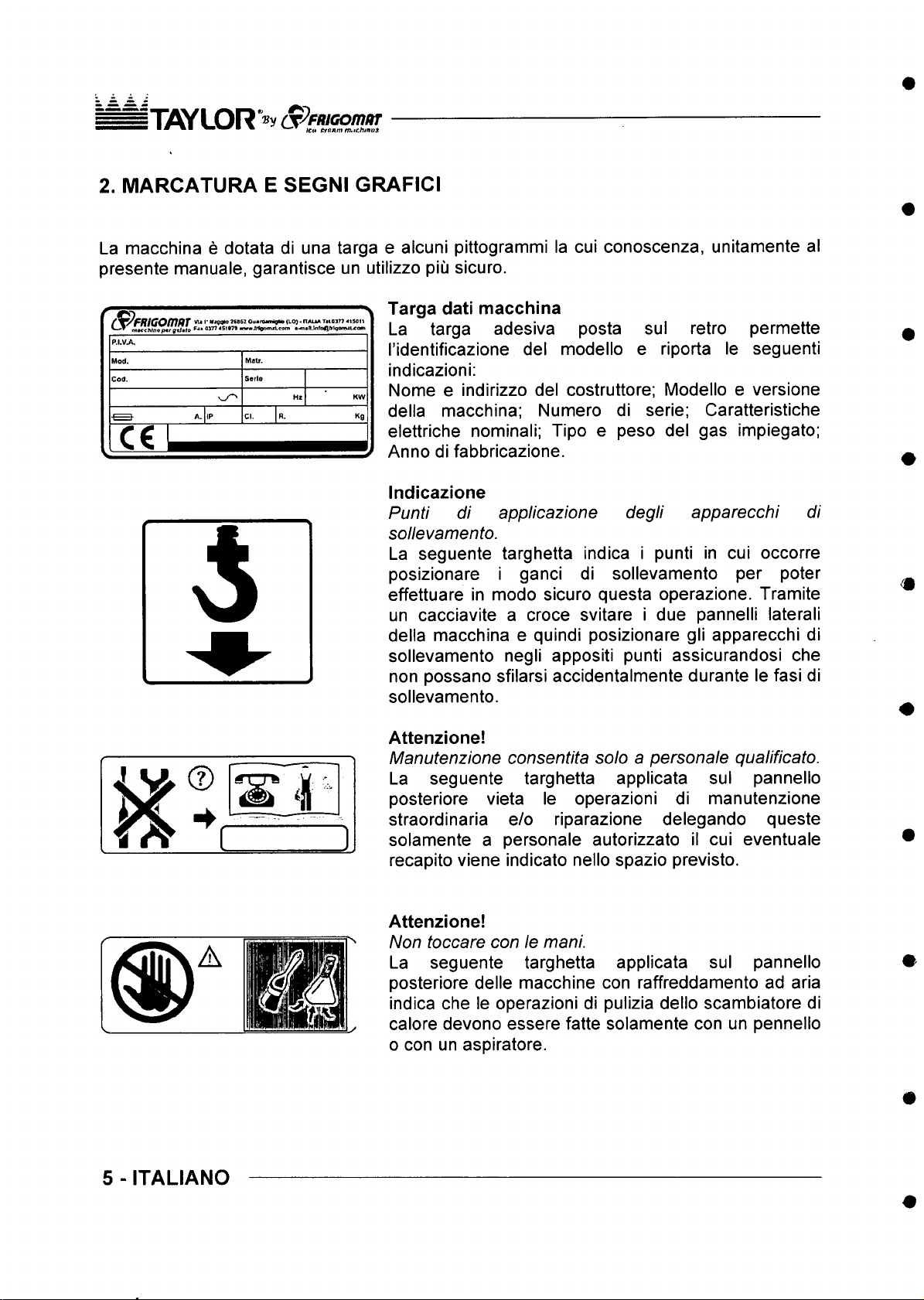
La macchina e dotata di una targa e alcuni pittogrammi la cui conoscenza, unitamente al
presente manuale, garantisce un utilizzo piu sicuro.
r R i C O fT t t tT '' *<00^^ ooira w^FW (10} • nAUA thoj tt aiso m
« 51»7B » w » J r t y > i n « i e o m »^ «H .l n fe ft B i1q a m U A O g i
C€
e - r j^ V
Targa dati macchina
La targa adesiva posta
I'identificazione del modello
sul retro permette
e riporta le seguenti
indicazioni;
Nome e indirizzo del costruttore; Modello e versione
della macchina: Numero di serie; Caratteristiche
K9
elettriche nominali; Tipo e peso del gas impiegato;
Anno di fabbricazione.
Indicazione
Pu nti di applicazione deg li app arecc hi di
solle vam en to.
La seguente targhetta indica i punti in cui occorre
posizionare i ganci di sollevamento per poter
effettuare in modo sicuro questa operazione. Tramite
un cacciavite a croce svitare i due pannelli laterali
della macchina e quindi posizionare gli apparecchi di
sollevamento negli appositi punti assicurandosi che
non possano sfilarsi accidentalmente durante le fasi di
sollevamento.
Attenzione!
M an ute nz io ne co nsentita solo a p ers on ale qualificato.
La seguente targhetta applicata sul pannello
posteriore vieta le operazioni di manutenzione
straordinaria e/o riparazione delegando queste
solamente a personale autorizzato il cui eventuale
recapito viene indicate nello spazio previsto.
5 - ITALIANO
Attenzione!
Non toccare con le mani.
La seguente targhetta applicata sul pannello
posteriore delle macchine con raffreddamento ad aria
indica che le operazioni di pulizia dello scambiatore di
calore devono essere fatte solamente con un pennello
o con un aspiratore.
Page 7
iT iifly L O R ‘®y (S^^ffUGom uT
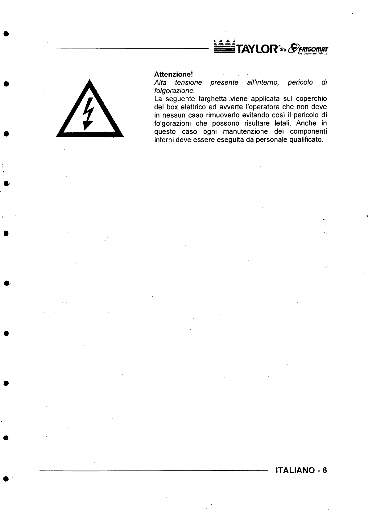
Attenzione!
Alta tension e pre se nte all’interno, pe rico lo di
folgorazione.
La seguente targhetta viene applicata sul coperchio
del box elettrico ed avverte I’operatore che non deve
in nessun caso rimuoverlo evitando cosi il pericolo di
folgorazioni che possono risultare letali. Anche in
questo caso ogni manutenzione dei componenti
interni deve essere eseguita da personale qualificato.
ITALIANO - 6
Page 8
iT if iY L O R * ® v S ^ fR iG o m a r
■ ,ca aenm riMci^tnas
3. NORME GENERALI Dl SICUREZZA
A p e r i c d l o A
Rispettare rigorosamente le norme general! di sicurezza e prevenzione infortuni di seguito
elencate:
- L’uso della macchina e consentito solo a personale in buono stato di salute,
responsabile e appositamente addestrato sugli usi consentiti e sui rischi present!.
- L’uso della macchina e consentito solo ad operator! che abbiano letto
completamente, compreso e assimilato quanto compreso nel presente manuale.
- E vietata la rimozione o la manomissione dei sistemi di sicurezza installati sulla
macchina.
- £ obbligatorio controllare che durante il funzionamento non si verifichino condizioni
di pericolo per le persone. In caso si manifestassero tali condizioni arrestare
immediatamente la macchina.
- E obbligatorio, dopo che si e terminate di lavorare con la macchina, togliere
tensione agendo sull’interruttore generate.
- E obbligatorio quando si rilevano rumorosita non abituali o anomalie di
funzionamento interrompere immediatamente ogni operazione in corso e ricercare
la causa di tali irregolarita. In caso di dubbio evitare operazioni improprie
rivolgendosi al servizio di assistenza tecnica del costruttore.
- Qualsiasi manomissione o modifica della macchina comporta automaticamente
I’immediata perdita della garanzia e sollevano il costruttore da ogni e qualsiasi
responsabilita per danni diretti o indiretti causati da tali manomissioni.
- E obbligatorio verificare che I’ambiente dove viene installata la macchina sia areato
e correttamente illuminate. La superfice su cui viene installata la macchina deve
essere solida, piana e ben livellata.
- £ obbligatorio durante le operazioni di carico, scarico e movimentazione utilizzare
apparecchi di sollevamento e movimentazione di portata adeguata alia massa
(peso) della macchina, impiegando dispositivi e accessor! di sollevamento di
caratteristiche e stato d’uso perfettamente idonei alio scope.
- Si raccomanda nelle operazioni di manutenzione di utilizzare solo ricambi originali
TAYLOR. II costruttore decline ogni responsabilita per danni causati dall’utilizzo di
accessor! non originali. L’uso di ricambi non originali comporta I’automatica perdita
della garanzia.
- E obbligatorio posizionare la macchina lontana da dispositivi che possano emettere
radiazioni elettromagnetiche che potrebbero provocare il cattivo funzionamento
delle schede elettroniche.
- Nel caso si renda necessario I’impiego di mezzi antincendio devono essere utilizzati
tipi compatibili con I’eventuale presenza di tensione a bordo.
- £ vietato indossare abiti lunghi e svolazzanti, cravatte, gioielli, sciarpe e altri
indumenti simili che potrebbero impigliarsi nelle parti mobili della macchina.
- I capelli lunghi vanno raccolti, le estremita delle maniche devono essere strette.
7 - ITALIANO
Page 9
s T A Y L O R "® y (S ^ fR K o m itr
■ ■ ^ ▼ fco Crn nm m ac hi n es
4. INSTALLAZIONE
4.1 IMPIEGHI
Apparecchio idoneo alia mantecazione delle miscele per gelato e alia produzione di
granita, secondo gli usi consentiti nei termini di Legge.
4.2 LIMITI DI IMPIEGO
Non utilizzare la macchina con tension! di alimentazione incostanti e/o oltre +/- 10% del
valore indicate in targa o con cavo di alimentazione danneggiato;
Non utilizzare la macchina in atmosfera esplosiva;
Non lavare la macchina con getti d’acqua ad alta pressione o con sostanze nocive;
Non esporre la macchina ad eccessivo calore o umidita;
Non impiegare miscele completamente sbilanciate e/o quantita non conform! alle
specifiche riportate sulle confezioni.
/ \ a vve rt en zaA
Gli usi non espressamente indicati nel presente manuale sono considerati impropri e
quindi tassativamente vietati. . .
II costruttore declina ogni e qualsiasi responsabilita per danni diretti o indiretti a persone,
animali o cose cagionati da un uso improprio della macchina.
4.3 RUMOROSITA’
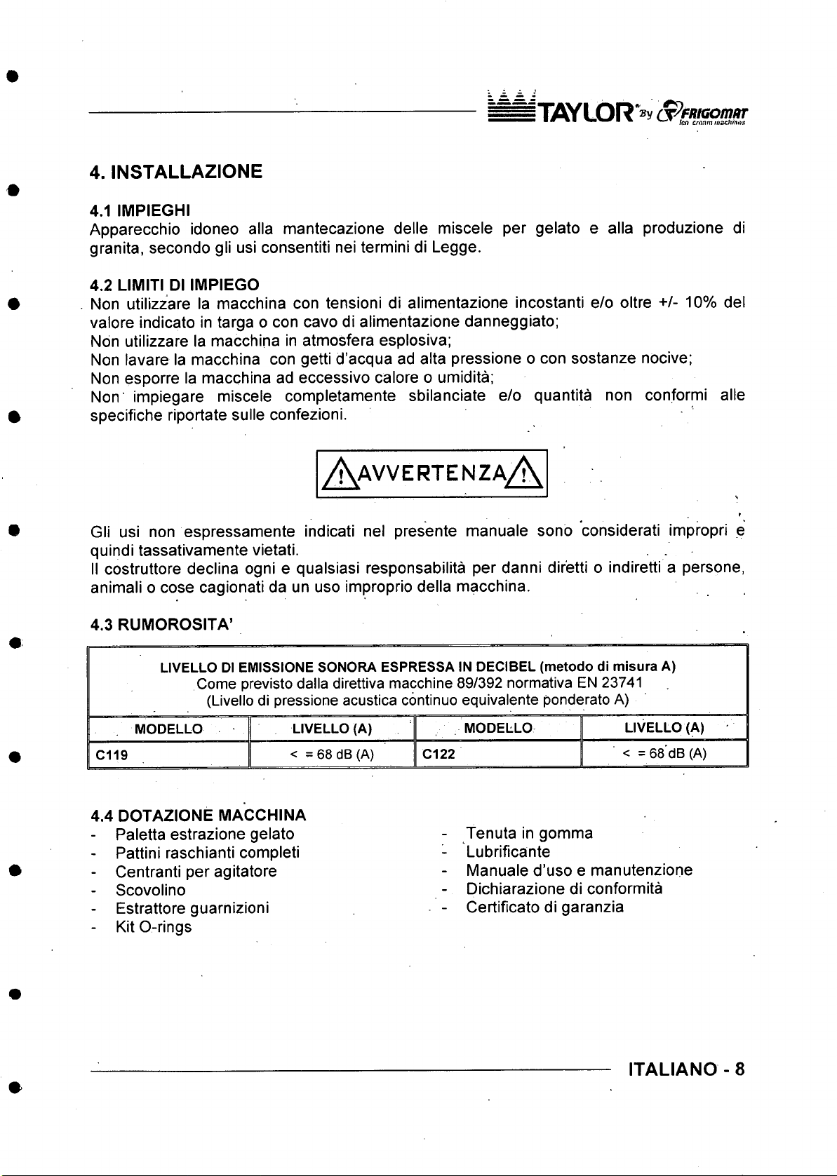
LIVELLO DI EMISSIONE SONORA ESPRESSA IN DECIBEL (metodo di misura A)
Come previsto dalla direttiva macchine 89/392 normativa EN 23741
(Livello di pressione acustica continue equivalente ponderate A)
LIVELLO (A)
< =68d B(A)
C119
MODELLO
LIVELLO (A) MODELLO
< =6 8dB( A) Cl 22
4.4 DOTAZIONE MACCHINA
- Paletta estrazione gelato
- Pattini raschianti completi
- Centranti per agitatore
- Scovolino
- Estrattore guarnizioni
Tenuta in gomma
Lubrificante
Manuale d’uso e manutenzione
Dichiarazione di conformita
Certificate di garanzia
- Kit 0-rings
ITALIANO - 8
Page 10
jT 7 S Y L 0 R '» y
■ *■ jjjg titofin^inachinss
4.5 MESSA IN FUNZIONE
A aVVERTENZaA
TAYLOR declina ogni e qualsiasi responsabilita per i danni causati dalla mancata
osservanza delle seguenti indicazioni. L’inosservanza e motivo della decadenza della
garanzia.
L’allacciamento della macchina alia rete idrica deve essere effettuato nel rispetto del
regolamenti nazionali del paesi dove si installa la macchina.
Per la messa in funzione, portare la macchina sul luogo di utilizzo verificando quanto
richiesto per la sua installazione:
1. Alimentazione elettrica 3 fasi + neutro + terra (5 fill - solo mod. trifase)
Alimentazione elettrica 2 fasi + terra (3 fili - solo mod. monofase);
2. Alimentazione acqua di rete fredda (13° - 20°C, solo mod. ad acqua);
3. Scarico per I’acqua di condensazione (solo mod. ad acqua).
• Verificare che la macchina sia posizionata su una superficie solida, stabile, piana e
livellata.
• Bloccare la macchina agendo suN’apposita leva di freno posta sulle ruote anteriori (solo
C119).
• Lasciare tra la macchina e le pareti o altri ostacoli almeno 10 cm dai pannelli laterali e
almeno 30 cm dal pannello posteriore. Nel caso di macchina con condensazione ad
acqua la distanza tra la parete ed il pannello posteriore puo essere di soli 10 cm.
• Verificare I’esatta corrispondenza tra la tensione e la potenza della rete di
alimentazione rispetto ai valori riportati nella targhetta dati posta sul pannello
posteriore;
• Collegare la macchina aH’impianto elettrico di alimentazione: prevedere a monte
dell’apparecchio un interruttore generale onnipolare con apertura minima dei contatti
pari a 3 mm di potenza adeguata, con sistema di protezione a fusibili o con
magnetotermico. Utilizzare una spina interbloccata di tipo approvato per permetterne
I’inserimento e il disinserimento solo a circuito aperto.
• II cavo deve essere ben steso, evitando arrotolamenti e sovrapposizioni, non esposto
ad eventual! urti o manomissioni; non deve essere in prossimita di liquid! o acqua e
font! di calore; non deve essere in alcun modo danneggiato, altrimenti farlo sostituire da
personate qualificato, prima dell’allacciamento della macchina alia rete, con un altro di
sezione e tipo 5G4 H07RN-F (versione 400 V), 5G6 H07RN-F (versione 220 V / 3).
• Ai fini della sicurezza, accertarsi che I’impianto di messa a terra a cui e collegata la
spina della macchina sia a norma e in perfetta efficienza.
9 - ITALIANO
Page 11

n i W L O R > (T^Fmaom oT
If needed, carry out an equipotential bonding,
using the screw placed on the rear of the machine
below the frame and marked with the symbol
shown to the left.
Make sure that the cold water supply line intended
for condensation has pressure values between 1
and 3 BAR and temperature between 13*" and
20X.
Connect the cold water supply pipe intended for
condensation onto the machine inlet as shown in
the figure. Use a 01/2" fitting and place a gate
valve in the operator's reach.
Connect the condensation water drain pipe onto
the machine outlet as shown in the figure, using a
01/2” fitting.
Always use new pipes suitable for hot water and
for pressure up to 10 bars both for delivery and
draining. Never use worn or consumed piping. Use
suitable DIN 3017 hose clamps.
The drain pipe must have an inclination of at least
3 cm for each meter of length.
After having connected the water inlet and outlet
pipes, with the machine stopped, open the cut-off
cock and make sure that water does not leak from
the drain.
Turn off the master switch and press the
PRODUCTION button to check the following:
1. Beater motor rotation direction (three-phase
models only).
The machine is equipped with a sophisticated
electronic system which is able to automatically
detect if the beater motor rotation direction is
the correct one (anti-clockwise).
If the phases are inverted in the plug, after a
few seconds of operating in production mode,
the machine stops and the display shows the
F23 alarm. To connect the phases properly cut
the power and invert the two phase wires in the
plug.
ENGLISH - 10
Page 12

iW LO R ^ ^ r P .’ lOfuM T
Condensation pressure (water models
2.
only).
With the machine in production mode, after a
few seconds condensation water must come
out of the drain pipe at a temperature of about
35°C. if this is not the case, the pressure switch
valve shown in the figure must be adjusted.
/ \ C A U T I □ N / \
Three-phase machines are powered with three-
phase + neutral lines: be careful never to
connect the phase lines with neutral. TAYLOR
will not be held liable for damage to the
machine deriving from incompliance with this
rule.
Press the STOP button to stop the machine .
Operating temperature should be between 15° and 35°C.
Humidity should be between 30 and 60%.
/ i\ p a n e e r A
TAYLOR will not be held liable for personal harm and/or damage to objects deriving from
incorrect installation and/or by failure to comply with work accident-prevention standards.
Never intervene on the machine with your hands, neither during normal operating cycles
nor during cleaning and maintenance, without first having stopped the machine by
pressing the STOP button and having turned off the master switch. Never clean the
appliance using a high-pressure water jet. Never shut the water cut-off cock while the
machine is running. Be careful never to damage the power cable. If so, have it replaced.
Machines with water cooling which are left in places at a temperature below or close to
0°C, must first have all the water drained from the condenser.
11 - ENGLISH
Page 13
ITifiy LOR »v (§ yfR iG o m a r
■ ■ * * ■ IcM crtmmn m tJtinna
5. DISPOSITIVI Dl SICUREZZA
Sicurezza anticesoiamento: Realizzata mediante circuito di sicurezza conforme alia
direttiva europea; interviene all’apertura del portello e/o al sollevamento della griglia di
sicurezza sulla tramoggia, commutando temporaneamente la macchina in STOP.
Sicurezza surriscaldamento motore agitatore: Realizzata mediante rele termico;
protegge da sovraccarichi il funzionamento del motore agitatore della macchina,
segnalando sul display il relative messaggio di allarme, emettendo un avviso acustico
intermittente e consentendo il ripristino direttamente da pulsantiera.
Sicurezza surriscaldamento motore compressore semiermetico: Realizzata mediante
rele termico a ripristino automatico; protegge da sovraccarichi il funzionamento del motore
compressore della macchina, segnalando sul display il relative messaggio di allarme,
emettendo un avviso acustico intermittente e consentendo il ripristino direttamente da
pulsantiera.
Sicurezza surriscaldamento motore compressore ermetico: Realizzata mediante
sensore termo-amperometrico a ripristino automatico: protegge da sovraccarichi il
funzionamento del motore compressore della macchina. L’intervento della protezione
determina I’arresto temporaneo del solo motore compressore.
Sicurezza sovrapressione circuito frigorifero: Realizzata mediante pressostato di
sicurezza approvato a ripristino automatico; protegge da sovrapressione I’integrita del
circuito frigorifero. L’intervento della protezione determina I’arresto temporaneo del solo
motore compressore.
Protezione contro il cortocirculto utenze ausiliarie: Realizzato da fusibili che
intervengono in caso di cortocircuito sull’unita logica o sull’alimentazione ausiliaria.
Circuito di sicurezza SELV: la pulsantiera e alimentata in bassa tensione tramite
trasformatore di sicurezza approvato a doppio isolamento, protetto da fusibili contro il
cortocircuito.
ITALIANO -12
Page 14
ITflY LOR S ^ F R K o m ttr
6. FUNZIONAMENTO
6.1 MACCHINA
A .
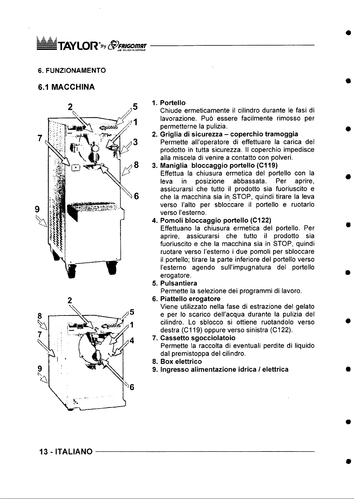
1. Portello
Chiude ermeticamente il cilindro durante le fasi di
lavorazione. Puo essere facilmente rimosso per
permetterne la pulizia.
2. Griglia di sicurezza - coperchio tramoggia
Permette all’operatore di effettuare la carica del
prodotto in tutta sicurezza. II coperchio impedisce
alia miscela di venire a contatto con polveri.
3. Maniglia bloccaggio portello (Cl 19)
Effettua la chiusura ermetica del portello con la
leva in posizione abbassata. Per aprire,
assicurarsi che tutto il prodotto sia fuoriuscito e
che la macchina sia in STOP, quindi tirare la leva
verso I’alto per sbloccare il portello e ruotarlo
verso I’esterno.
4. Pomoli bloccaggio portello (C l22)
Effettuano la chiusura ermetica del portello. Per
aprire, assicurarsi che tutto il prodotto sia
fuoriuscito e che la macchina sia in STOP, quindi
ruotare verso I’esterno i due pomoli per sbloccare
il portello: tirare la parte inferiore del portello verso
I’esterno agendo sull’impugnatura del portello
erogatore.
5. Pulsantiera
Permette la selezione dei programmi di lavoro.
6. Piattello erogatore
Viene utilizzato nella fase di estrazione del gelato
e per lo scarico dell’acqua durante la pulizia del
cilindro. Lo sblocco si ottiene ruotandolo verso
destra (Cl 19) oppure verso sinistra (Cl22).
7. Cassette sgocciolatoio
Permette la raccolta di eventuali perdite di liquido
dal premistoppa del cilindro.
8. Box elettrico
9. Ingresso alimentazione idrica / elettrica
13-ITALIANO
Page 15
6.2 COMANDI
ITflYLOR »y S ^fM G onuiT
■ * ■ ^ tea CfanmmnchhMSi
□
u
Q
U
□
o
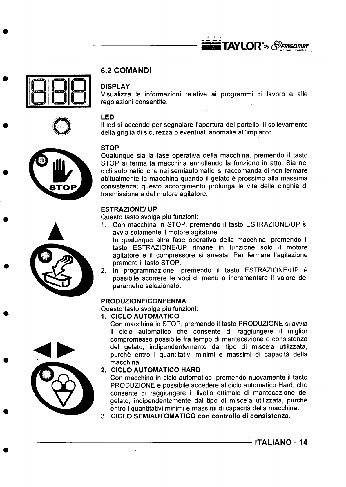
DISPLAY
Visualizza le informazioni relative ai programmi di lavoro e alle
regolazioni consentite.
LED
II led si accende per segnalare I’apertura del portello, il sollevamento
della griglia di sicurezza o eventuali anomalie airimpianto.
STOP
Qualunque sia la fase operativa della macchina, premendo il tasto
STOP si ferma la macchina annullando la funzione in atto. Sia nei
cicii automatici che nei semiautorhatici si raccomanda di non fermare
abitualmente la macchina quando il gelato e prossimo alia massima
consistenza; questo accorgimento prolunga la vita della cinghia di
trasmissione e del motore agitatore.
ESTRAZIONE/ UP
Questo tasto svolge piu funzioni:
1. Con macchina in STOP, premendo il tasto ESTRAZIONE/UP si
avvia solamente il motore agitatore.
In qualunque altra fase operativa della macchina, premendo il
tasto ESTRAZIONE/UP rimane in funzione solo il motore
agitatore e il compressore si arresta. Per fermare I’agitazione
premere il tasto STOP.
2. In programmazione, premendo il tasto ESTRAZIONE/UP e
possibile scorrere le voci di menu o incrementare il valore del
parametro selezionato.
PRODUZIONE/CONFERMA
Questo tasto svolge piu funzioni:
1. CICLO AUTOMATICO
Con macchina in STOP, premendo il tasto PRODUZIONE si avvia
il cicio automatico che consente di raggiungere il miglior
compromesso possibile fra tempo di mantecazione e consistenza
del gelato, indipendentemente dal tipo di miscela utilizzata,
purche entro i quantitativi minimi e massimi di capacita della
macchina.
2. CICLO AUTOMATICO HARD
Con macchina in cicio automatico, premendo nuovamente il tasto
PRODUZIONE e possibile accedere al cicio automatico Hard, che
consente di raggiungere il livello ottimale di mantecazione del
gelato, indipendentemente dal tipo di miscela utilizzata, purche
entro i quantitativi minimi e massimi di capacita della macchina.
3. CICLO SEMIAUTOMATICO con controllo di consistenza.
ITALIANO - 14
Page 16
j“|y S Y L O R '® y S ^ffa G o m a r
■ *■ ■ m » tr.a Cf(*t\fninAe/unBS
Con macchina in cicio automatico Hard, premendo nuovamente il
tasto PRODUZIONE e possibile accedere al cicio semiautomatico
con controllo di consistenza, che consente all’operatore di
selezionare manualmente il livello di consistenza che si vuole
ottenere.
4. Con macchina in programmazione, premendo il tasto
PRODUZiONE/CONFERMA si conferma la selezione della voce
di menu o il valore del parametro selezionato.
CICLO SEMIAUTOMATICO A TEMPO/DOWN
Questo tasto svolge piu funzioni:
1. CICLO SEMIAUTOMATICO con controllo del tempo.
Con macchina in STOP, premendo il tasto CICLO
SEMIAUTOMATICO A TEMPO/DOWN e possibile accedere al
cicio semiautomatico con controllo del tempo di mantecazione,
che consente all’operatore di selezionare manualmente il tempo
di lavorazione della propria miscela.
2. In programmazione, premendo ii tasto CICLO
SEMIAUTOMATICO A TEMPO/DOWN e possibile scorrere le
voci di menu o diminuire il valore del parametro selezionato.
PRODUZIONE GRANITA
Con macchina in STOP, premendo il tasto PRODUZIONE GRANITA
si abilitano i programmi GR1 con controllo di consistenza e
agitazione continua, e GR2 con controllo del tempo e agitazione
ciclica.
15-ITALIANO
Page 17
I l if iy L O R V ^ f f l/ G O / n / i r
■ ^ /CO e/rtfimnisc/jma*
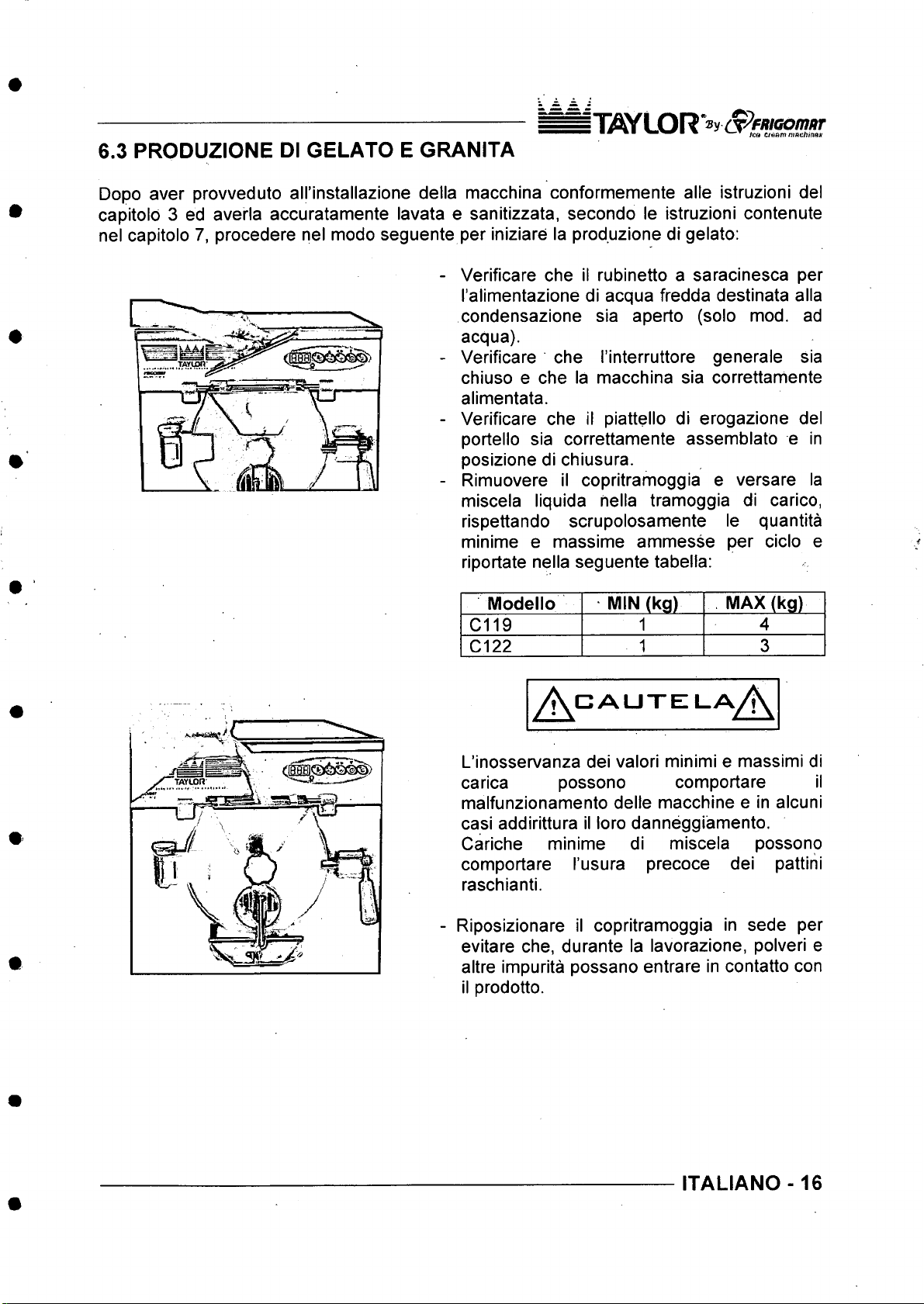
6.3 PRODUZIONE Dl GELATO E GRANITA
Dopo aver provveduto all’installazione della macchina conformemente alle istruzioni del
capitold 3 ed averla accuratamente lavata e sanitizzata, secondo le istruzioni contenute
nel capitolo 7, procedere nel modo seguente per iniziare la produzione di gelato:
- Verificare che il rubinetto a saracinesca per
I’alimentazione di acqua fredda destinata alia
condensazione sia aperto (solo mod. ad
acqua).
- Verificare che I’interruttore generale sia
chiuso e che la macchina sia correttamente
alimentata.
- Verificare che il piattello di erogazione del
portello sia correttamente assemblato e in
posizione di chiusura.
- Rimuovere il copritramoggia e versare la
miscela liquida nella tramoggia di carico,
rispettando scrupolosamente le quantita
minime e massime ammesse per cicio e
riportate nella seguente tabella:
Modello
C119
C122 1 3
A '
L’inosservanza dei valori minimi e massimi di
carica possono comportare il
malfunzionamento delle macchine e in alcuni
casi addirittura il loro danneggiamento.
Cariche minime di miscela possono
comportare I’usura precoce dei pattini
raschianti.
Riposizionare il copritramoggia in sede per
evitare che, durante la lavorazione, polveri e
altre impurita possano entrare in contatto con
il prodotto.
MIN (kg)
1
CAUTEILA
MAX (kg)
4
A
ITALIANO -16
Page 18
n y S Y L O R * ® y (S ^ fitK o m a r
• ^ ica ctmmtneiC.hina%
6.3.1 CICLO AUTOMATICO
Fig.2
Fig.3
n
P
r i
u O U
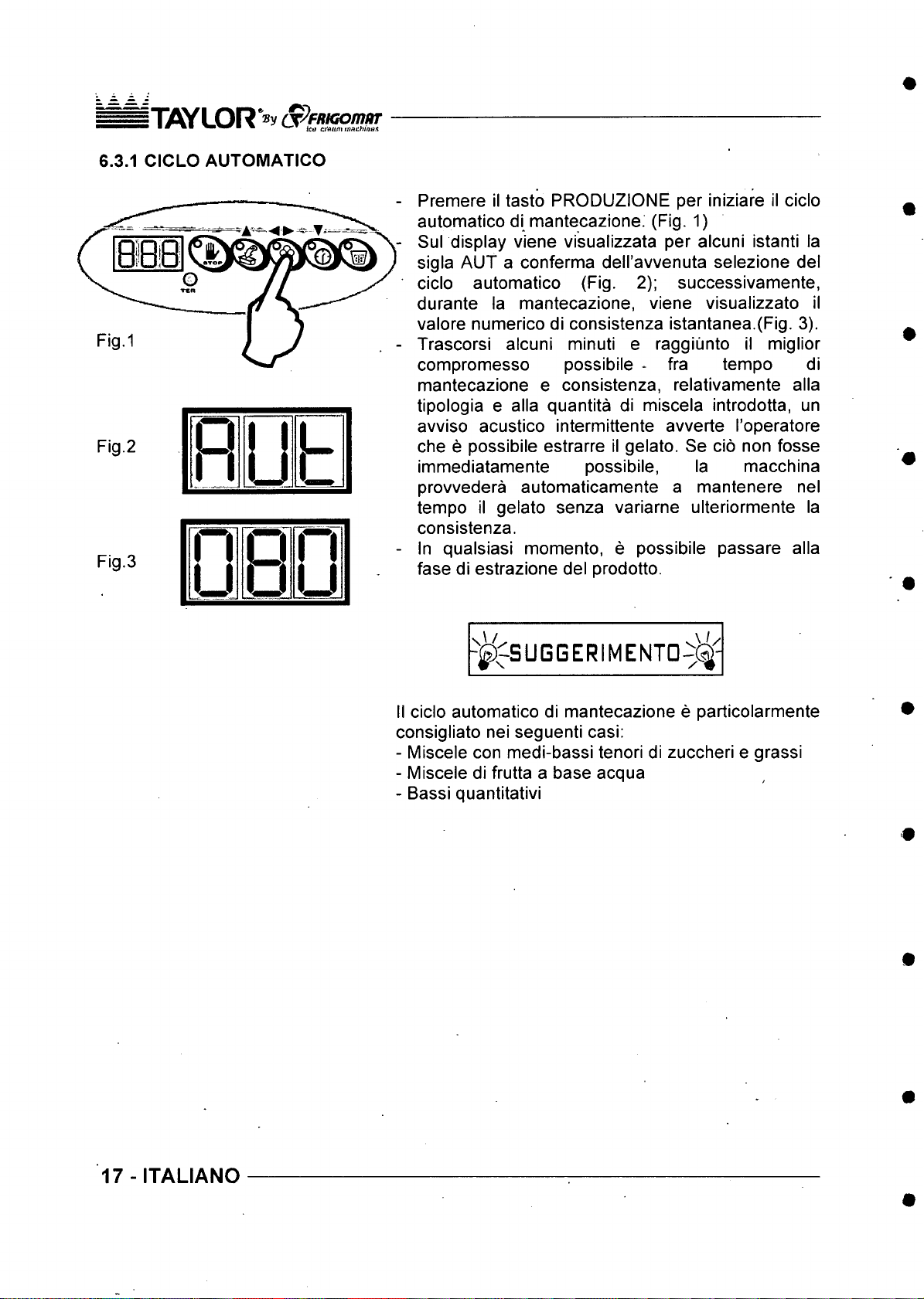
Premere il tasto PRODUZIONE per iniziare il cicio
automatico di mantecazione. (Fig. 1)
Sul display viene visualizzata per alcuni istanti la
sigla AUT a conferma deH’avvenuta selezione del
cicio automatico (Fig. 2); successivamente,
durante la mantecazione, viene visualizzato il
valore numerico di consistenza istantanea.(Fig. 3).
Trascorsi alcuni minuti e raggiunto il miglior
compromesso possibile * fra tempo di
mantecazione e consistenza, relativamente alia
tipologia e alia quantita di miscela introdotta, un
avviso acustico intermittente avverte I’operatore
che e possibile estrarre il gelato. Se do non fosse
immediatamente possibile, la macchina
provvedera automaticamente a mantenere nel
tempo il gelato senza variarne ulteriormente la
consistenza.
In qualsiasi momento, e possibile passare alia
fase di estrazione del prodotto.
-|)^SUGGERIMENTD-5 ^-
II cicio automatico di mantecazione e particolarmente
consigliato nei seguenti casi:
- Miscele con medi-bassi tenori di zuccheri e grassi
- Miscele di frutta a base acqua
- Bassi quantitativi
17 - ITALIANO
Page 19
6.3.2 CiCL0 AUTOMATICO HARD-
Fig.2
Fig.3
R l y
h
I T if lY LOR (X ^ FRiG o m /iT
• ■ m w - T ir.o aaum tu nch utH it
Premere il tasto PRODUZIONE per iniziare il cicio
automatico di mantecazione, come descritto nel
paragrafo precedente.
Sul display viene visualizzata per alcuni istanti la
sigla AUT a conferma deH’avvenuta selezione del
cicio automatico.
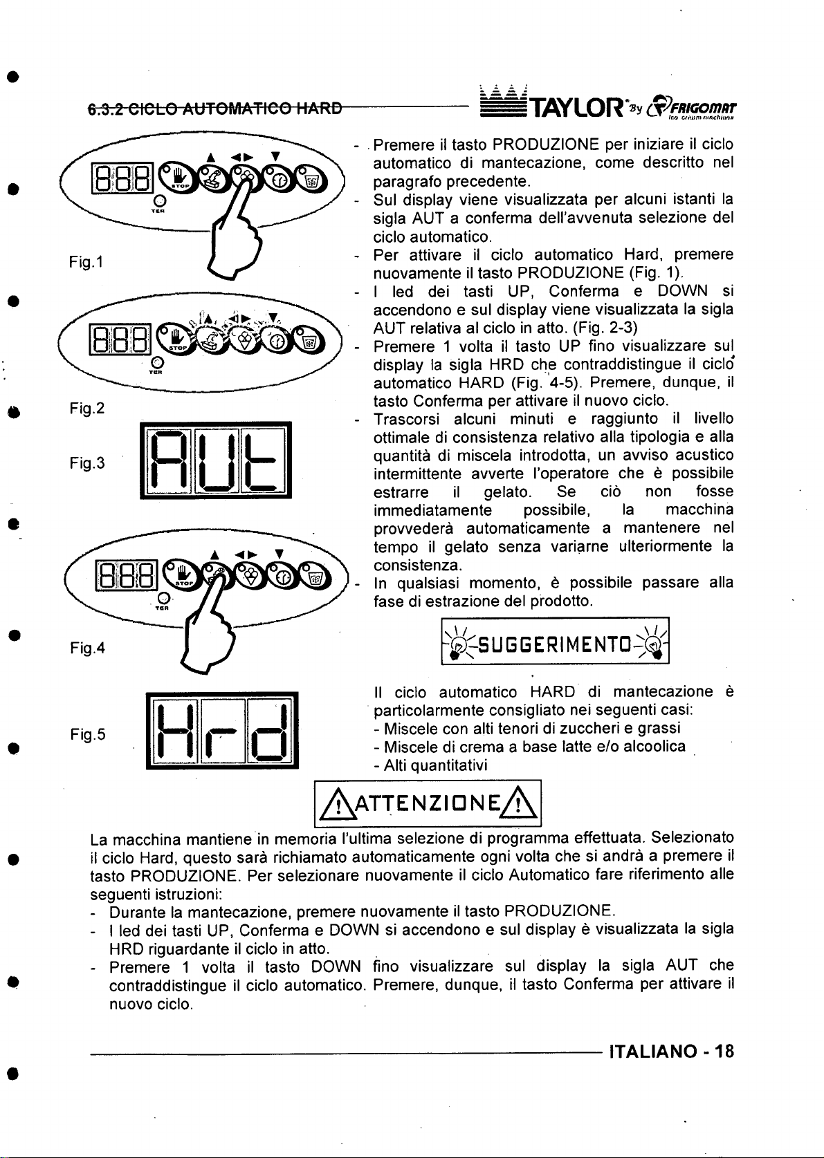
Per attivare il cicio automatico Hard, premere
nuovamente il tasto PRODUZIONE (Fig. 1).
I led dei tasti UP, Conferma e DOWN si
accendono e sul display viene visualizzata la sigla
AUT relativa al cicio in atto. (Fig. 2-3)
Premere 1 volta il tasto UP fino visualizzare sul
display la sigla HRD che contraddistingue il cicio
automatico HARD (Fig. 4-5). Premere, dunque, il
tasto Conferma per attivare il nuovo cicio.
Trascorsi alcuni minuti e raggiunto il livello
ottimale di consistenza relative alia tipologia e alia
quantita di miscela introdotta, un avviso acustico
intermittente avverte I’operatore che e possibile
estrarre il gelato. Se do non fosse
immediatamente possibile, la macchina
provvedera automaticamente a mantenere nel
tempo il gelato senza variarne ulteriormente la
consistenza.
In qualsiasi momento, e possibile passare alia
fase di estrazione del prodotto.
A /
^^SUGGERIMENTD-^(f
II cicio automatico HARD di mantecazione e
particolarmente consigliato nei seguenti casi;
- Miscele con alti tenori di zuccheri e grassi
- Miscele di crema a base latte e/o alcoolica
- Alti quantitativi
Fig.5
L.
I r
1
o
A attenzioneA
La macchina mantiene in memoria I’ultima selezione di programme effettuata. Selezionato
il cicio Hard, questo sara richiamato automaticamente ogni volta che si andra a premere il
tasto PRODUZIONE. Per selezionare nuovamente il cicio Automatico fare riferimento alle
seguenti istruzioni:
- Durante la mantecazione, premere nuovamente il tasto PRODUZIONE.
- I led dei tasti UP, Conferma e DOWN si accendono e sul display e visualizzata la sigla
HRD riguardante il cicio in atto.
- Premere 1 volta il tasto DOWN fino visualizzare sul display la sigla AUT che
contraddistingue il cicio automatico. Premere, dunque, il tasto Conferma per attivare il
nuovo cicio.
ITALIANO -18
Page 20
I'TO/LOR S^fR Kio m iiT
6.3.3 CICLO SEMIAUTOMATICO CON CONTROLLO Dl CONSISTENZA (solo utenti
esperti)
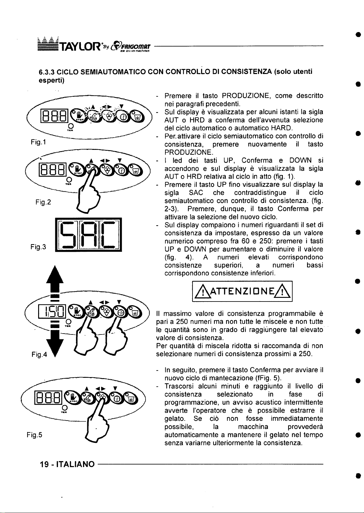
Premere il tasto PRODUZIONE, come descritto
nei paragrafi precedenti.
Sul display e visualizzata per alcuni istanti la sigla
AUT o HRD a conferma dell’avvenuta selezione
del cicio automatico o automatico HARD.
Per.attivare il cicio semiautomatico con controllo di
consistenza, premere nuovamente il tasto
PRODUZIONE.
I led dei tasti UP, Conferma e DOWN si
accendono e sul display e visualizzata la sigla
AUT 0 HRD relativa al cicio in atto (fig. 1).
Premere il tasto UP fino visualizzare sul display la
sigla SAC che contraddistingue il cicio
semiautomatico con controllo di consistenza. (fig.
2-3). Premere, dunque, il tasto Conferma per
attivare la selezione del nuovo cicio.
• Sul display compaiono i numeri riguardanti il set di
consistenza da impostare, espresso da un valore
numerico compreso fra 60 e 250: premere i tasti
UP e DOWN per aumentare o diminuire il valore
(fig. 4). A numeri elevati corrispondono
consistenze superiori, a numeri bassi
corrispondono consistenze inferiori.
Fig.3
c
[ J
R l n
h
L
Fig.4
19 -ITALIANO
A attenzioneA
II massimo valore di consistenza programmabile e
pari a 250 numeri ma non tutte le miscele e non tutte
le quantita sono in grado di raggiiingere tal elevato
valore di consistenza.
Per quantita di miscela ridotta si raccomanda di non
selezionare numeri di consistenza prossimi a 250.
- In seguito, premere il tasto Conferma per avviare il
nuovo cicio di mantecazione (fFig. 5).
- Trascorsi alcuni minuti e raggiunto il livello di
consistenza selezionato in fase di
programmazione, un avviso acustico intermittente
avverte I’operatore che e possibile estrarre il
gelato. Se do non fosse immediatamente
possibile, la macchina provvedera
automaticamente a mantenere il gelato nel tempo
senza variarne ulteriormente la consistenza.
Page 21
5 T flY L O R * ® y cpeRfG o m nT
■ ■% •' V - ▼ h:a r..'oam »wch!nos
In qualsiasi momento, e possibile passare alia
fase d’estrazione del prodotto.
- j ^ ^ S U G G E R I M E N T D ^ ^ -
Al fine di correggere eventual! errori di
programmazione iniziali, durante I’esecuzione del
cicio semiautomatico e sempre possibile variare il set
di consistenza impostato tramite la seguente
procedura:
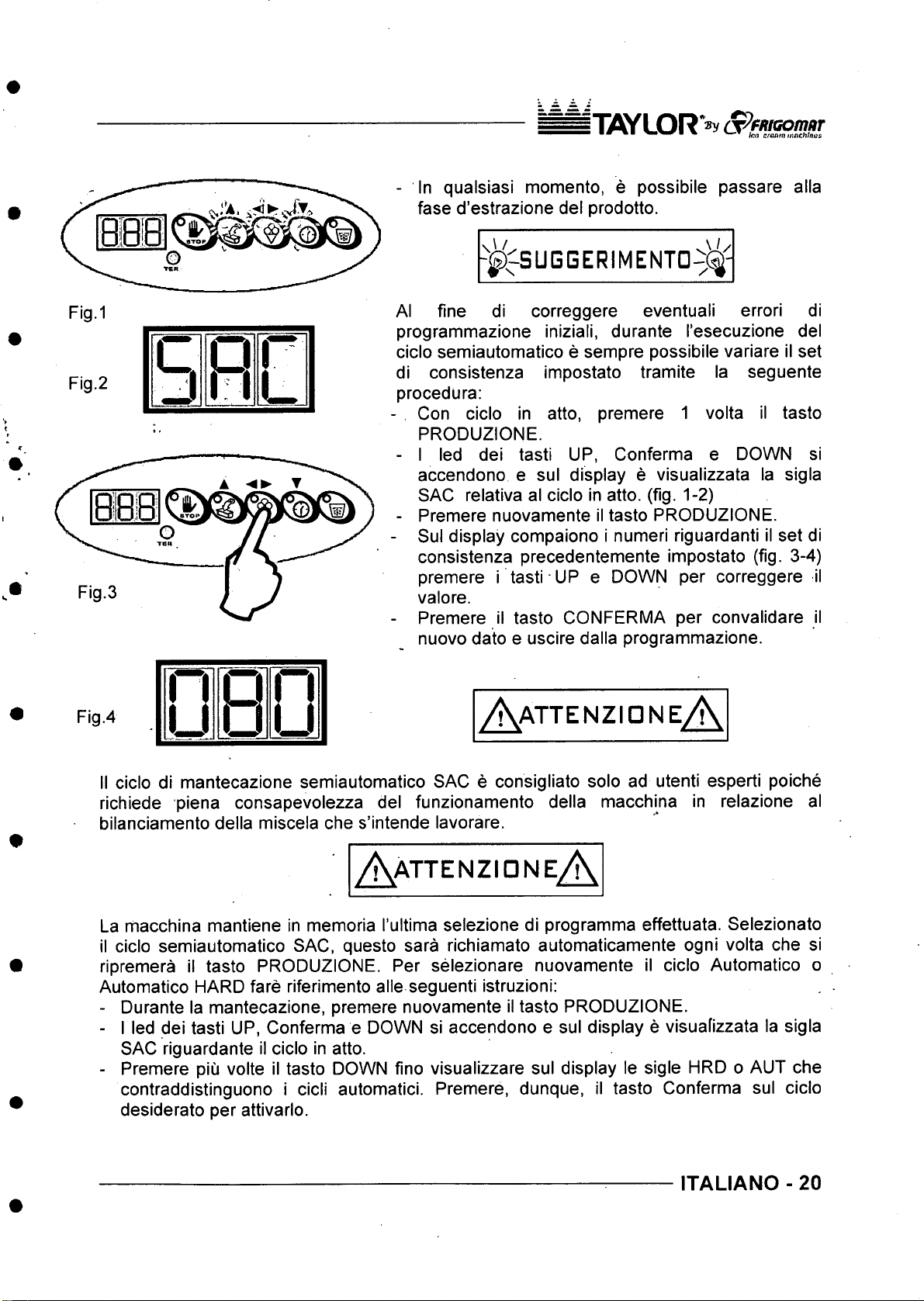
- Con cicio in atto, premere 1 volta il tasto
PRODUZIONE.
- I led dei tasti UP, Conferma e DOWN si
accendono e sul display e visualizzata la sigla
SAC relativa al cicio in atto. (fig. 1-2)
- Premere nuovamente il tasto PRODUZIONE.
- Sul display compaiono i numeri riguardanti il set di
consistenza precedentemente impostato (fig. 3-4)
premere i tasti UP e DOWN per correggere il
valore.
- Premere il tasto CONFERMA per convalidare il
nuovo dato e uscire dalla programmazione.
Fig.4
II cicio di mantecazione semiautomatico SAC e consigliato solo ad utenti esperti poiche
richiede piena consapevolezza del funzionamento della macchina in relazione al
bilanciamento della miscela che s’intende lavorare.
A a t t e n z ion e A
A a t t e n z io n e A
La macchina mantiene in memoria I’ultima selezione di programma effettuata. Selezionato
il cicio semiautomatico SAC, questo sara richiamato automaticamente ogni volta che si
ripremera il tasto PRODUZIONE. Per selezionare nuovamente il cicio Automatico o
Automatico HARD fare riferimento alle seguenti istruzioni:
- Durante la mantecazione, premere nuovamente il tasto PRODUZIONE.
- I led dei tasti UP, Conferma e DOWN si accendono e sul display e visuafizzata la sigla
SAC riguardante il cicio in atto.
- Premere piu volte il tasto DOWN fino visualizzare sul display le sigle HRD o AUT che
contraddistinguono i deli automatic!. Premere, dunque, il tasto Conferma sul cicio
desiderato per attivarlo.
ITALIANO - 20
Page 22
I T iOY L O R c p F R K o m a r
6.3.4 CICLO SEMIAUTOMATICO CON CONTROLLO DEL TEMPO (solo utenti esperti)
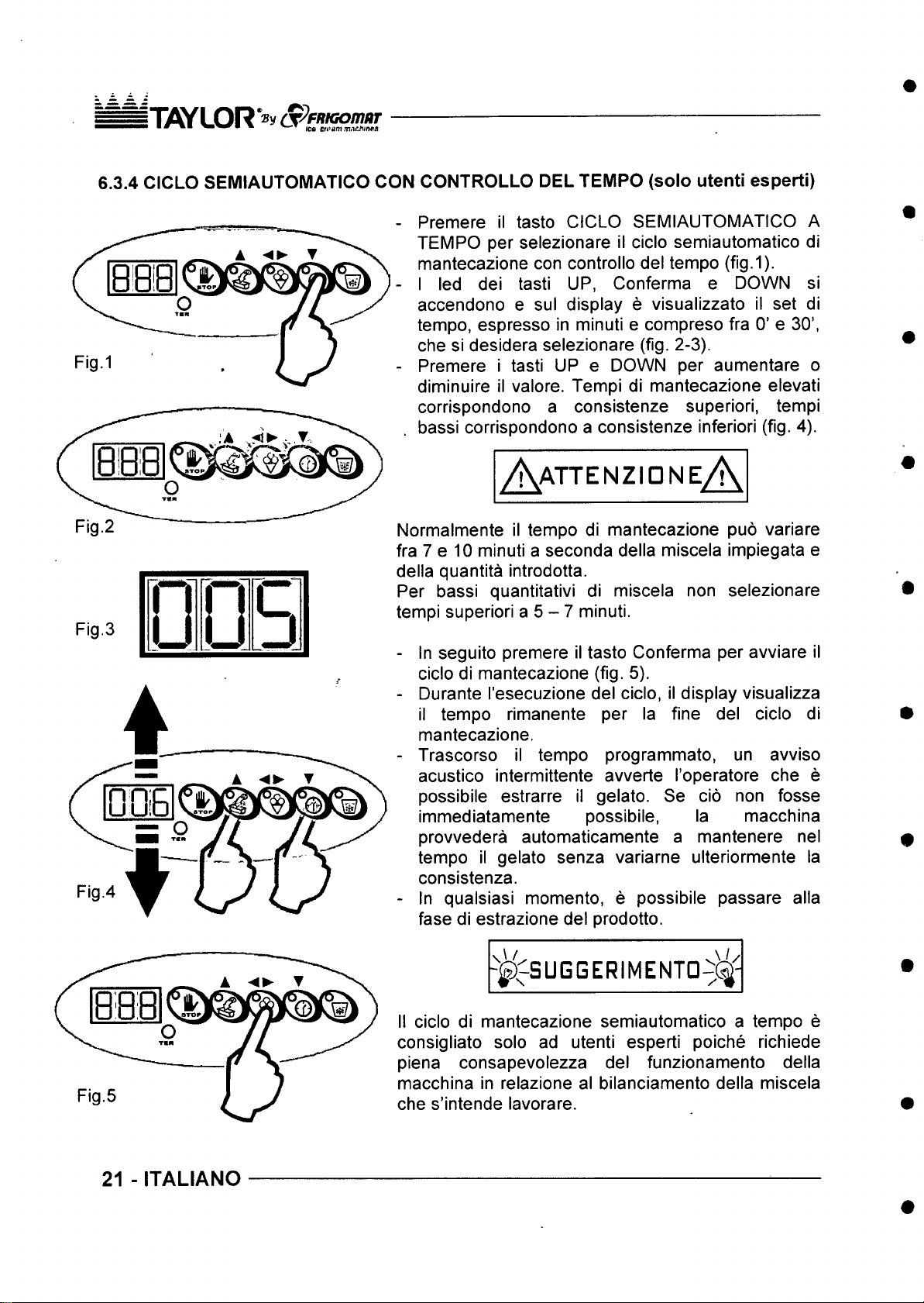
Premere il tasto CICLO SEMIAUTOMATICO A
TEMPO per selezionare il cicio semiautomatico di
mantecazione con controllo del tempo (fig.1).
I led dei tasti UP, Conferma e DOWN si
accendono e sul display e visualizzato il set di
tempo, espresso in minuti e compreso fra 0’ e 30’,
che si desidera selezionare (fig. 2-3).
Premere i tasti UP e DOWN per aumentare o
diminuire il valore. Tempi di mantecazione elevati
corrispondono a consistenze superiori, tempi
bassi corrispondono a consistenze inferiori (fig. 4).
A a t t e n z i d n e A
Fig.2
Fig.3
m
U l
n
u
\ Q
u J
Normalmente il tempo di mantecazione puo variare
fra 7 e 10 minuti a seconda della miscela impiegata e
della quantita introdotta.
Per bassi quantitativi di miscela non selezionare
tempi superiori a 5 - 7 minuti.
- In seguito premere il tasto Conferma per avviare il
cicio di mantecazione (fig. 5).
- Durante I’esecuzione del cicio, il display visualizza
il tempo rimanente per la fine del cicio di
mantecazione.
- Trascorso il tempo programmato, un avviso
acustico intermittente avverte I’operatore che e
possibile estrarre il gelato. Se do non fosse
immediatamente possibile, la macchina
provvedera automaticamente a mantenere nel
tempo il gelato senza variarne ulteriormente la
consistenza.
- In qualsiasi momenta, e possibile passare alia
fase di estrazione del prodotto.
- ^ ^ S U G G E R I M E N T D ^ ^ -
21 - ITALIANO
II cicio di mantecazione semiautomatico a tempo e
consigliato solo ad utenti esperti poiche richiede
piena consapevolezza del funzionamento della
macchina in relazione al bilanciamento della miscela
che s’intende lavorare.
Page 23
i T W L O R ’®y (S^FRIGOmOT
• ■ " ^ ^ ^ hui crow n m pch hwi
/K attenzidne
Al fine di correggere eventuali ''errori di
programmazione iniziali, durante' I’esecuzione del
cicio semiautomatico e sempre possibile variare il set
di tempo impostato tramite la seguente prqcedura:
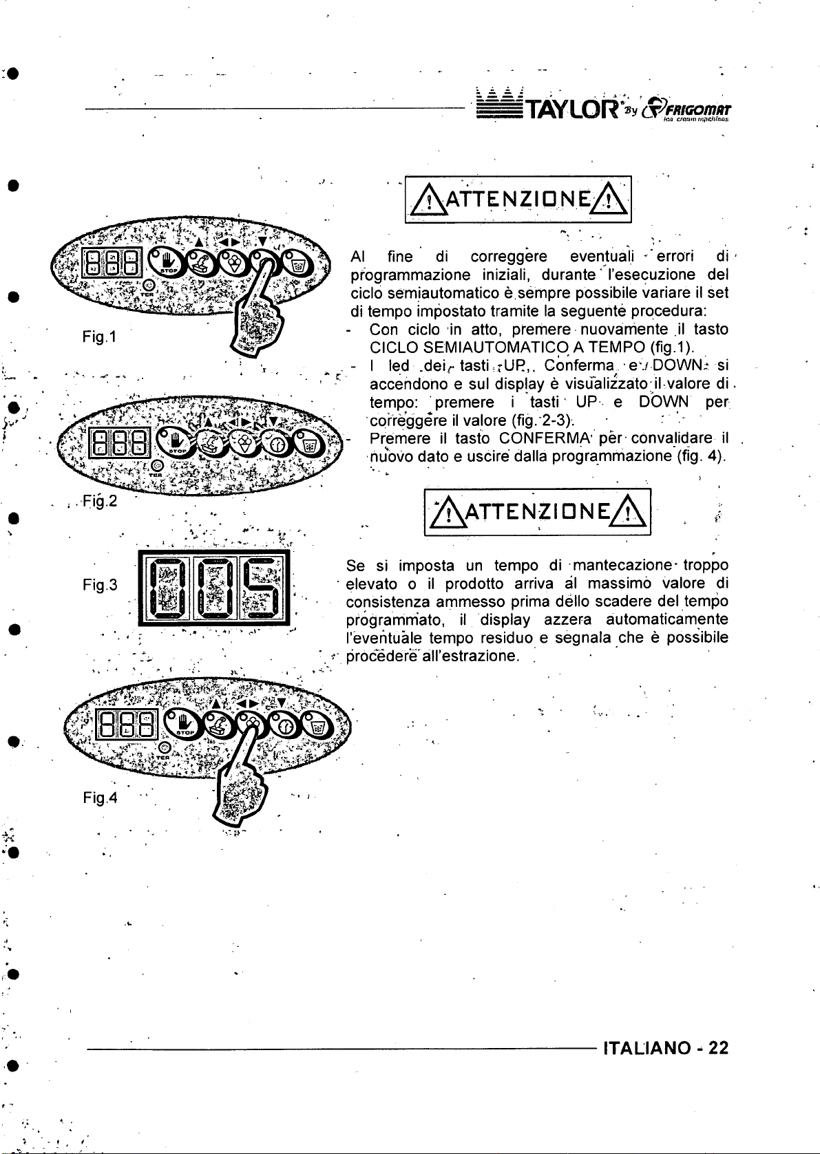
Con cicio in atto, prerhere nuovamente il tasto
CICLO SEMIAUTOMATICpATEMPO (fig.1).
- I led .deir tasti ^rUR,. Gonferma^ ev DOWN.- si
a -
accendono e sul display e visualizzato il valore di
tempo: premere i tasti UP e DOWN per
cprreggere il valore (fig.‘2-3).
Premere il tasto CONFERMA per convalidare il
nuovo dato e uscire dalla programmazione (fig. 4).
Fig.2
Fig.3
\w
TKattenzid ne
Se si imposta un tempo di mantecazione-troppo
elevato o il prodotto arriva al massimo valore di
consistenza ammesso prima dello scadere del tempo
pfogramm'ato, il display azzera automaticamente
I’everituale tempo residuo e segnala che e possibile
procedere all’estrazione.
ITALIANO - 22
Page 24
ififlYLOR (jp F R K o m itT
■ *■ ■ m WT tea tmarnmitthrma
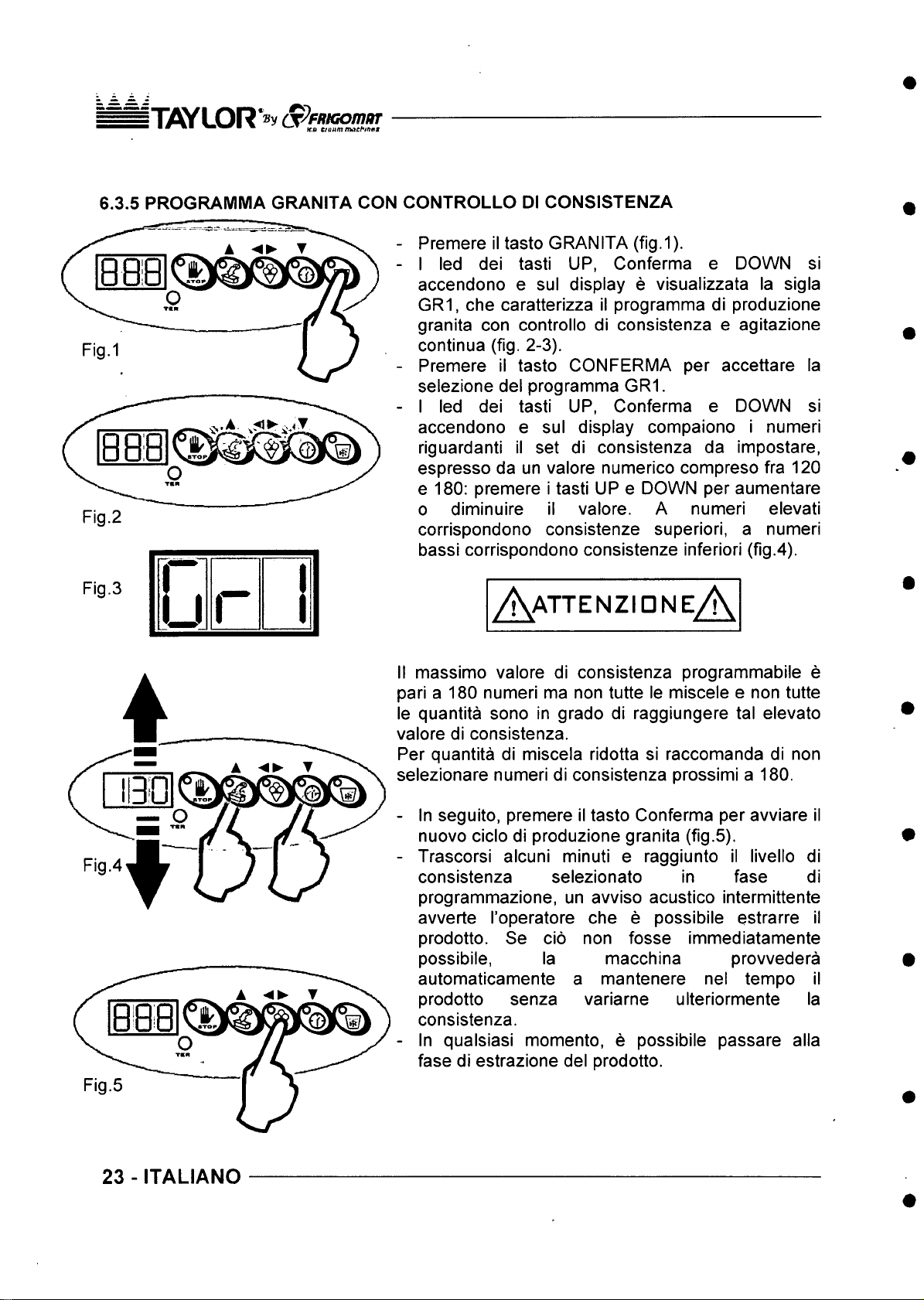
6.3.5 PROGRAMMA GRANITA CON CONTROLLO Dl CONSISTENZA
Premere il tasto GRANITA (fig.1).
I led del tasti UP, Conferma e DOWN si
accendono e sul display e visualizzata la sigla
GR1, che caratterizza il programma di produzione
granita con controllo di consistenza e agitazione
continua (fig. 2-3).
Premere il tasto CONFERMA per accettare la
selezione del programma GR1.
I led dei tasti UP, Conferma e DOWN si
accendono e sul display compaiono i numeri
riguardanti il set di consistenza da impostare,
espresso da un valore numerico compreso fra 120
e 180: premere i tasti UP e DOWN per aumentare
Fig.2
0 diminuire il valore. A numeri elevati
corrispondono consistenze superiori, a numeri
bassi corrispondono consistenze inferiori (fig.4).
Fig.3
u
r
/ \ attenzidne/ \
II massimo valore di consistenza programmabile e
pari a 180 numeri ma non tutte le miscele e non tutte
le quantita sono in grado di raggiungere tal elevato
valore di consistenza.
Per quantita di miscela ridotta si raccomanda di non
selezionare numeri di consistenza prossimi a 180.
- In seguito, premere il tasto Conferma per avviare il
nuovo cicio di produzione granita (fig.5).
- Trascorsi alcuni minuti e raggiunto il livello di
consistenza selezionato in fase di
programmazione, un avviso acustico intermittente
avverte I’operatore che e possibile estrarre il
prodotto. Se do non fosse immediatamente
possibile, la macchina provvedera
automaticamente a mantenere nel tempo il
prodotto senza variarne ulteriormente la
consistenza.
- In qualsiasi momento, e possibile passare alia
fase di estrazione del prodotto.
23 - ITALIANO
Page 25
^ T if l Y L O R V S ^ fitiG o iim iT
■ kinaraitm marMs
.L/.
<U /
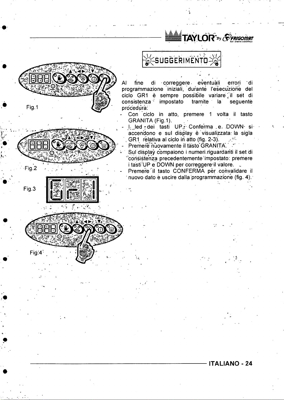
■^SUGGERIMENTD^(%
Al fine di correggere- eventual! error! d!
programmazione !n!z!al!, durante I’esecuzione del
cicio GR1 e sempre posslBlIe varlare jF set d!
consistenza ' Impostato tramite la seguente
prdcedura:
- Con cIcIo In atto, premere 1 volta !l tasto
GRANITA (F!g.1).
- I; Jed rde! tast! UP,r Confe’rma .e. DOWN- s!
accendono e sul display e visualizzata: la sigla
, GR1 relativa al cicio in atto (fig. 2-3).
- Premefe huovamente il tasto'GRANITA.'
h
Fig.2
Fig.3
T.’'-
•<
- Sul display compaiono i numeri riguardariti il set di
cdrisistenza precedentemente’impostato: premere
i tasti'UP e DOWN per correggere-il valore. ^
- Premere il tasto CONFERMA per cohyalidare il
nuovo dato e uscire dalla programmazione (fig. 4).
ITALIANO - 24
Page 26
ifTSYLOR^y (S^fM G omar
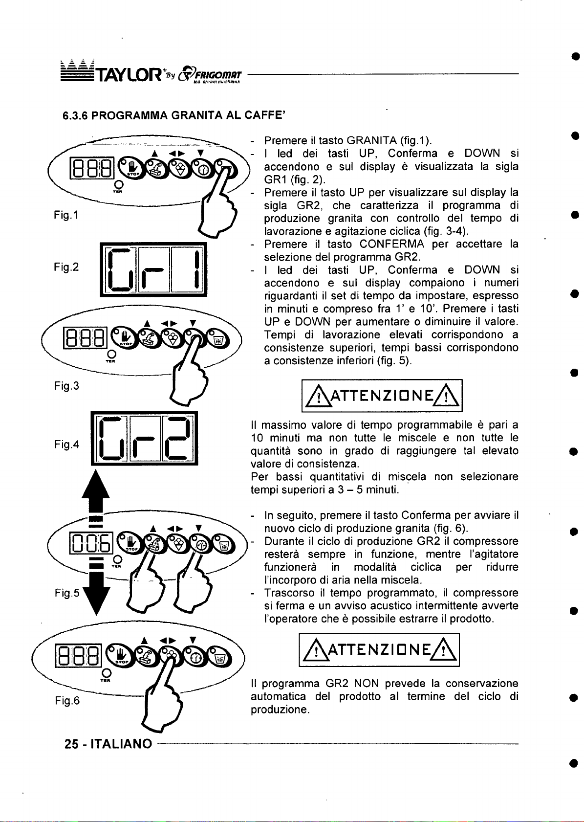
6.3.6 PROGRAMMA GRANITA AL CAFFE’
- Premere il tasto GRANITA (fig.1).
- I led del tasti UP, Conferma e DOWN si
- Premere il tasto UP per visualizzare sul display la
- Premere il tasto CONFERMA per accettare la
Fig.2
c
r
A ▼
- I led dei tasti UP, Conferma e DOWN si
R 11 1
O
TCR
accendono e sul display e visualizzata la sigla
GR1 (fig. 2).
sigla GR2, che caratterizza il programma di
produzione granita con controllo del tempo di
lavorazione e agitazione ciclica (fig. 3-4).
selezione del programma GR2.
accendono e sul display compaiono i numeri
riguardanti il set di tempo da impostare, espresso
in minuti e compreso fra T e 10’. Premere i tasti
UP e DOWN per aumentare o diminuire il valore.
Tempi di lavorazione elevati corrispondono a
consistenze superiori, tempi bassi corrispondono
a consistenze inferiori (fig. 5).
Fig.3
Fig.4
G
r
a
A a t t e n z i d n e A
II massimo valore di tempo programmabile e pari a
10 minuti ma non tutte le miscele e non tutte le
quantita sono in grado di raggiungere tal elevato
valore di consistenza.
Per bassi quantitativi di miscela non selezionare
tempi superiori a 3 - 5 minuti.
- In seguito, premere il tasto Conferma per avviare il
nuovo cicio di produzione granita (fig. 6).
- Durante il cicio di produzione GR2 il compressore
restera sempre in funzione, mentre I’agitatore
funzionera in modalita ciclica per ridurre
I’incorporo di aria nella miscela.
- Trascorso il tempo programmato, il compressore
si ferma e un avviso acustico intermittente avverte
I’operatore che e possibile estrarre il prodotto.
A a t t e n z io n e A
25 - ITALIANO
II programma GR2 NON prevede la conservazione
automatica del prodotto al termine del cicio di
produzione.
Page 27
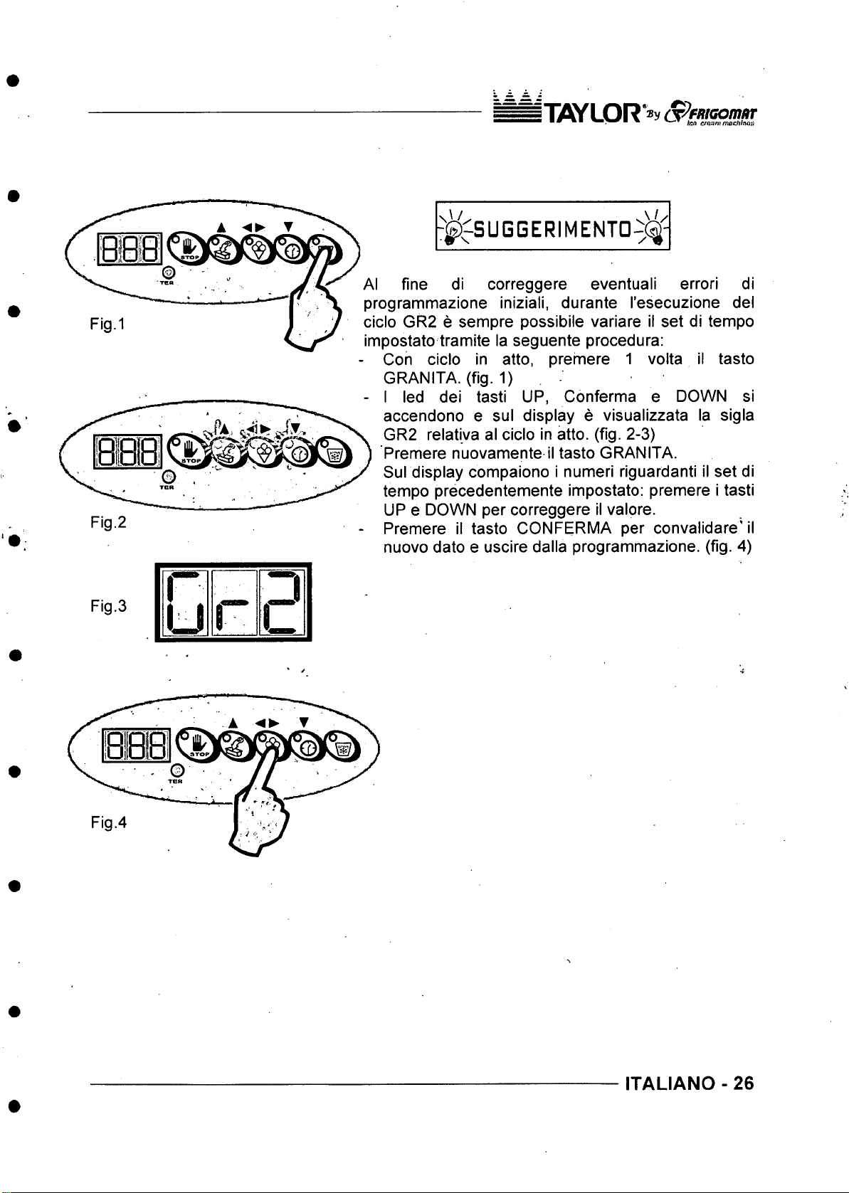
Fig.2
5TflYLOR‘®y
■ ■ " * ■ ^ ▼ Ia n cfonm m ochhoa
- ^ ^ S U G G E R IM E N T D - 5 ^-
Al fine di correggere eventual! errori di
programmazione iniziali, durante I’esecuzione del
cicio GR2 e sempre possibile variare II set di tempo
impostato tramite la seguente procedura:
Con cicio in atto, premere 1 volta il tasto
GRANITA. (fig. 1)
- I led dei tasti UP, Conferma e DOWN si
accendono e sul display e visualizzata la sigla
GR2 relativa al cicio in atto. (fig. 2-3)
Premere nuovamente il tasto GRANITA.
Sul display compaiono i numeri riguardanti il set di
tempo precedentemente impostato: premere i tasti
UP e DOWN per correggere il valore.
Premere il tasto CONFERMA per convalidare' il
nuovo dato e uscire dalla programmazione. (fig. 4)
Fig.3
ITALIANO - 26
Page 28
IT ifi y LOR S ^f/ttG o m iir
■ KO etanninMciiinfift
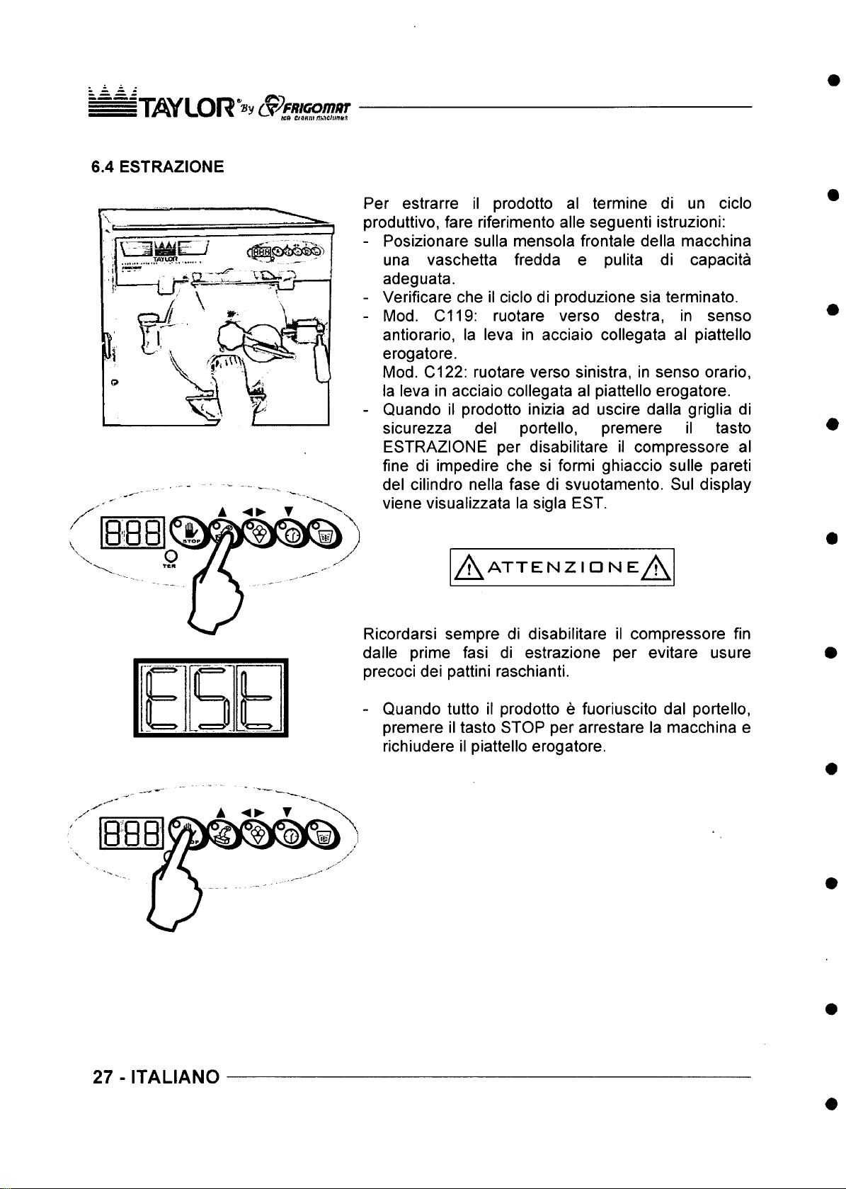
6.4 ESTRAZIONE
Per estrarre il prodotto al termine di un cicio
produttivo, fare riferimento alle seguenti istruzioni:
- Posizionare sulla mensola frontale della macchina
una vaschetta fredda e pulita di capacita
adeguata.
- Verificare che il cicio di produzione sia terminato.
- Mod. C119: ruotare verso destra, in senso
antiorario, la leva in acciaio collegata al piattello
erogatore.
Mod. C122: ruotare verso sinistra, in senso orario,
la leva in acciaio collegata al piattello erogatore.
- Quando il prodotto inizia ad uscire dalla griglia di
sicurezza del portello, premere il tasto
ESTRAZIONE per disabilitare il compressore al
fine di impedire che si formi ghiaccio sulle pareti
del cilindro nella fase di svuotamento. Sul display
viene visualizzata la sigla EST.
(U
I ■ - —^
AT TEN Z I ON E
A
Ricordarsi sempre di disabilitare il compressore fin
dalle prime fasi di estrazione per evitare usure
precoci dei pattini raschianti.
- Quando tutto il prodotto e fuoriuscito dal portello,
premere il tasto STOP per arrestare la macchina e
richiudere il piattello erogatore.
A
27 - ITALIANO
Page 29

Iw U D R ^ v ^FR H x> m m ‘
7. MAINTENANCE
7.1 ROUTINE MAINTENANCE (INTENDED FOR USER)
A aTTENTIDN A
The fats present in the ice cream mixtures are ideal fields for the proliferation of bacterial
loads and mould. To eliminate this serious problem, all the parts which come into contact
with the product must be thoroughly washed and sanitised by careful procedures and
using suitable sanitising products. The stainless and plastic materials used on our
machines, in fact, comply with the strictest international provisions and their special shape
facilitates their washing. However this is not enough to prevent the formation of mould and
bacteria caused by insufficient or incorrect cleaning.
TAYLOR recommends thoroughly washing and sanitising the parts in direct contact with
the product after each work shift and in compliance with hygienic standards in force in the
Country where the machine is installed.
To correctly clean your machine, refer to the following operations:
PREWASHING
Pour the maximum admitted load of warm
(approximately 50°C) drinking water into the
machine.
Press the ESTRAZIONE (EXTRACTION) button in
order to start the beater motor and let it run for about
3'. Open the dispenser disk to drain all the wash
water. Repeat the procedure until the water coming
out is clear and clean.
Pour the maximum load admitted
cleansing/sanitising solution into the machine.
Press the ESTRAZIONE (EXTRACTION) button in
order to start the beater motor and let it run for about
15'. Open the dispenser disk to drain all the
sanitising solution.
We suggest using the following sanitising
solution:^:
of
Ecolab P3 Topax-san
(4% dilution = 200 ml).
ENGLISH -28
Page 30

:TflYLOR"®y orV/w(so/nar-
Pour the maximum admitted load of cold drinking
water into the machine to rinse the surfaces which
were just treated with the sanitiser.
Drain the rinse water and turn the machine off.
When pre-washing is over, all the removable parts in
contact with the product must be disassembled and
sanitised in a separate tub.
SANITISING REMOVABLE PARTS
PREPARATION OF WASHING TUB
Wash your hands well and/or wear disposable
gloves.
Fill a clean tub with a sufficient amount of drinking
water at approximately 50°C and the sanitizer.
Prepare the supplied brush and the OR disassembly
We suggest using the following sanitising
solution:
Ecolab P3 Topax-san
1
\
(4% dilution = 200 ml every 5 litres of water).
device and immerse them in the solution.
REMOVING AND CLEANING THE DOOR {C119)
Lift the blocking lever and open the door by rotating it
to the left.
Pull the hinge pin upwards and remove the door,
holding it with both hands.
A w a r n in g A
Handle the door with great care: because of its great
weight, should it fall, it could cause injuries to staff and
damages to things.
29 - ENGLISH
• Rest the door on a clean work surface and
disassemble its parts:
7. Remove the plastic lid from the hopper.
8. Unscrew and remove the plastic knob.
Page 31

iW L O R *By (y^fR iG om /ir
9. Remove the steel lever that controls the
dispenser disk from the central door pin.
10. Remove the spring.
11. Remove the dispenser disk.
12. Use the OR disassembly device to remove the 2
OR gaskets from their place.
Immerse the previously disassembled components
into the tub with the sanitising solution and brush the
surfaces with care. Pay special attention to the safety
grid and gaskets.
REMOVING AND CLEANING THE DOOR (C122)
Rotate the two knobs to unblock the door outwards,
pull the lower part of the door outwards acting on the
lever handle that controls the dispenser disk.
Remove the door holding it with both hands.
A w a r n in g A
Handle the door with great care: because of its great
weight, should it fall, it could cause injuries to staff
and damages to things.
Rest the door on a clean work surface and
disassemble its parts:
1. Remove the plastic lid from the hopper.
2. Unscrew and remove the plastic knob.
3. Remove the steel lever that controls the dispenser
disk from the central door pin.
4. Remove the spring.
5. Remove the dispenser disk.
6. Use the OR disassembly device to remove the 2
OR gaskets from their place.
Immerse the previously disassembled components
into the tub with the sanitising solution and brush the
surfaces with care. Pay special attention to the safety
grid and gaskets.
ENGLISH -30
Page 32

iWLOR By ^P p fu cpnw r-
REMOVING AND CLEANING STIRRER
Pull the beater towards you to remove it from the
batch freezing cylinder.
Recover the seal gasket placed on the back of the
beater.
Remove the scrapers from the beater by pressing
firmly on the small fixing tooth.
Remove the metallic springs from the scrapers.
Immerse the previously disassembled components
into the tub with the sanitising solution and brush the
surfaces with care. Pay special attention to the seats
of the scrapers and metallic springs.
A aTTENTIDN A
All the disassembled parts must remain soaking in the Ecolab P3 Topax-san sanitizer
(4% dilution) for at least 15’ before they are rinsed with plenty of cold drinking water.
SANITISING FIXED PARTS
While the removable parts soak in the sanitizer
inside the tub, proceed sanitising the fixed parts of
the machine:
SANITISING THE CYLINDER
Immerse a disposable paper cloth in the sanitising
liquid.
Pass the cloth over all the cylinder surfaces.
Also pass the cloth over the outer edge of the
cylinder until reaching the surfaces of the front panel
and bib.
A at tenti dn A
Never use any type of solvents and/or thinners to preserve the plastic parts and
gaskets during washing.
Chemical sanitising products must be used in compliance with standards in force and
with the utmost caution.
During sanitising operations, do not touch parts with tissues, sponges, rags or any
other non-sterile material.
31 - ENGLISH
Page 33
^TiWLOR ®y S^fK K iom ar
■ ■" • ■ #ro c^o/mi ;Hflc/j/n.»ji
RISCIACQUO E ASCIUGATURA
Lavarsi bene le mani e/o utilizzare guanti monouso in
lattice.
Estrarre dalla vasca di sanificazione tutti i componenti
precedentemente smontati, scovolinati e immersi.
Sciacquarli con abbondante acqua potabile fredda
avendo cura di rimuovere tutti i possibili residui di
soluzione sanificante.
Appoggiare i componenti risciacquati con acqua su un
banco puiito e lasciare asciugare all’ aria.
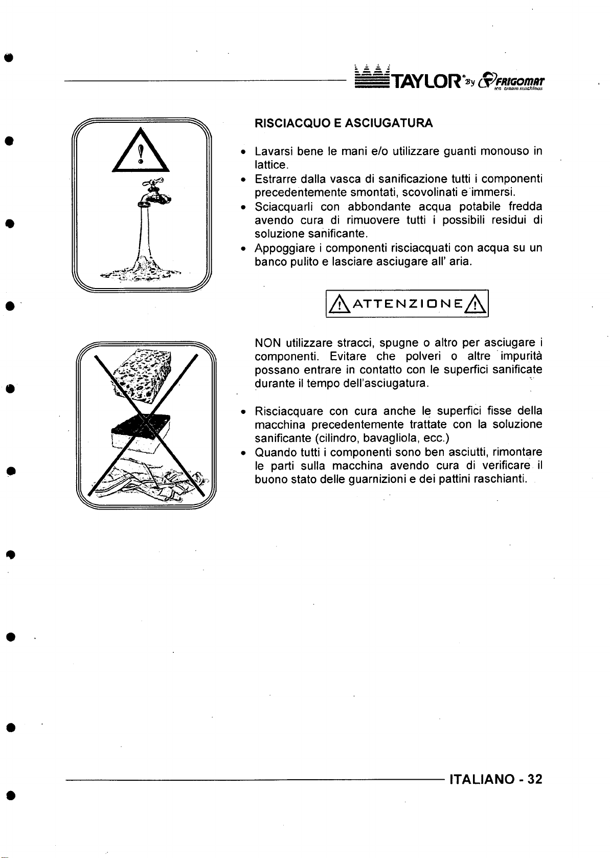
/ \ A T T E N Z m N E / \
NON utilizzare stracci, spugne o altro per asciugare i
componenti. Evitare die polveri o altre impurita
possano entrare in contatto con le superfici sanificate
durante il tempo dell’asciugatura.
Risciacquare con cura anche le superfici fisse della
macchina precedentemente trattate con la soluzione
sanificante (cilindro, bavagliola, ecc.)
Quando tutti i componenti sono ben asciutti, rimontare
le parti sulla macchina avendo cura di verificare il
buono state delle guarnizioni e dei pattini raschianti.
ITALIANO - 32
Page 34
TO/LOR'»y appftiG o m m
*■ ■ ■■ ■ ^ tea ttaniutrjtO'.itiKH
7.2 MANUTENZIONE STRAORDINARIA (RIVOLTO AL PERSONALE QUALIFICATO)
C AU TE LA
A '
Queste operazioni devono essere eseguite solo ed esclusivamente da personale
qualificato autorizzato. TAYLOR S.r.l. declina ogni responsabilita per danni a cose o
persone che possano verificarsi a causa dall’inosservanza di quanto sopra.
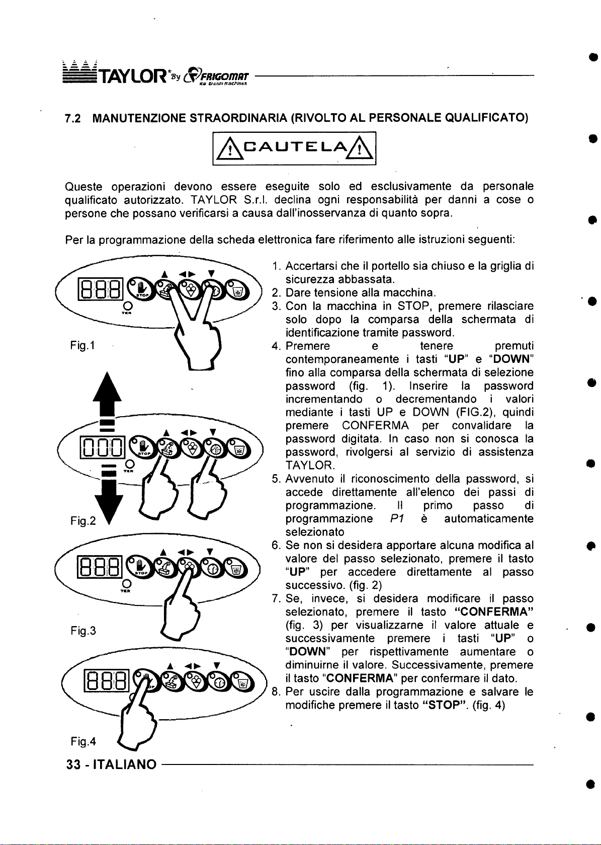
Per la programmazione della scheda elettronica fare riferimento alle istruzioni seguenti:
1. Accertarsi che II portello sia chiuso e la griglia di
sicurezza abbassata.
2. Dare tensione alia macchina.
3. Con la macchina in STOP, premere rilasciare
solo dopo la comparsa della schermata di
identificazione tramite password.
4. Premere e tenere premuti
contemporaneamente i tasti “UP” e “DOWN”
fino alia comparsa della schermata di selezione
password (fig. 1). Inserire la password
incrementando o decrementando i valori
mediante i tasti UP e DOWN (FIG.2), quindi
premere CONFERMA per convalidare la
password digitata. In caso non si conosca la
password, rivolgersi al servizio di assistenza
TAYLOR.
5. Awenuto il riconoscimento della password, si
accede direttamente all’elenco dei passi di
programmazione. II primo passo di
programmazione
selezionato
6. Se non si desidera apportare alcuna modifica al
valore del passo selezionato, premere il tasto
“UP” per accedere direttamente al passo
successivo. (fig. 2)
7. Se, invece, si desidera modificare il passo
selezionato, premere il tasto “CONFERMA”
(fig. 3) per visualizzarne il valore attuale e
successivamente premere i tasti “UP” o
“DOWN” per rispettivamente aumentare o
diminuirne il valore. Successivamente, premere
ii tasto “CONFERMA” per confermare il dato.
8. Per uscire dalla programmazione e salvare le
modifiche premere il tasto “STOP”, (fig. 4)
A
P1 e automaticamente
Fig.4
33 - ITALIANO
Page 35
5T7SYLOR"®y (S^fRiG om ur
■ ■ " • ■ /firt <yea,ii
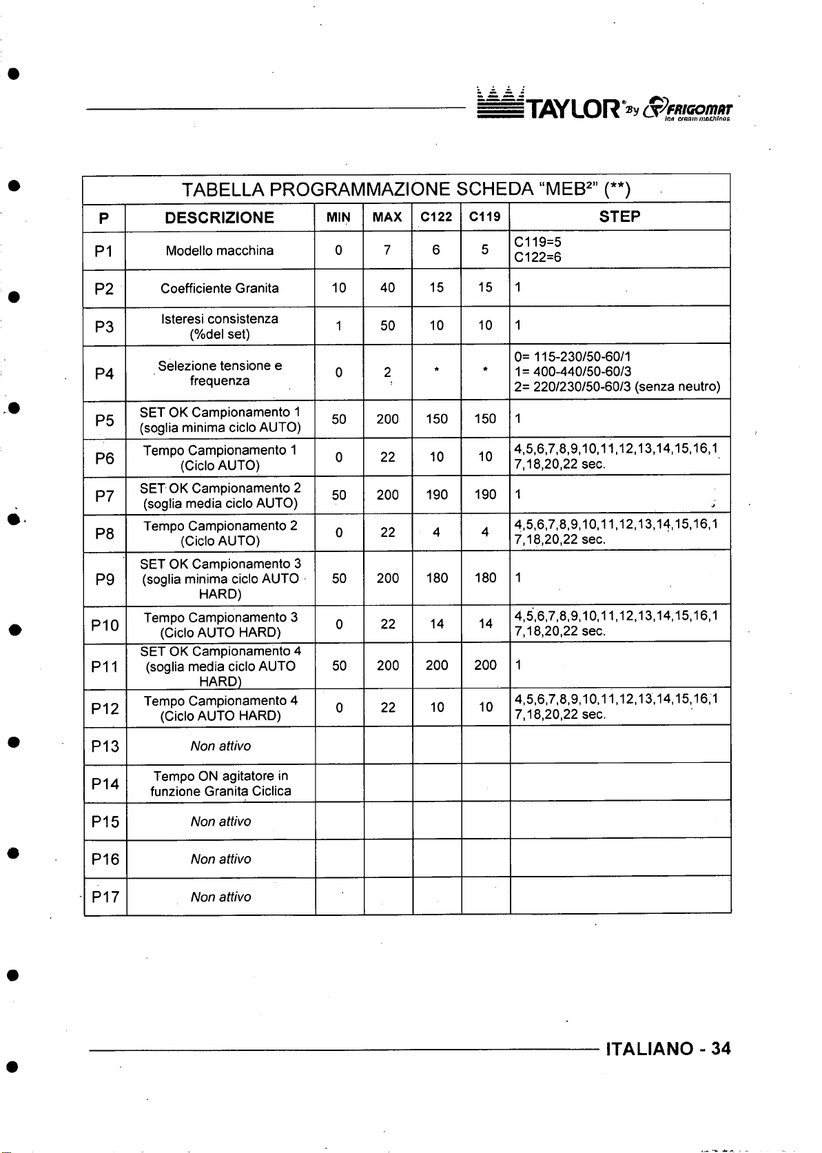
TABELLA PROGRAMM A ZIONE SCHEDA “MEB^” (**)
P
P1
P2
P3
P4
P5
P6
P7
P8
P9
P10
P11
P12
DESCRIZIONE
Modello macchina
Coefficiente Granita
Isteresi consistenza
(%del set)
Selezione tensione e
frequenza
SET OK Campionamento 1
(soglia minima cicio AUTO)
Tempo Campionamento 1
(Cicio AUTO)
SET OK Campionamento 2
(soglia media cicio AUTO)
Tempo Campionamento 2
(Cicio AUTO)
SET OK Campionamento 3
(soglia minima cicio AUTO
HARD)
Tempo Campionamento 3
(Cicio AUTO HARD)
SET OK Campionamento 4
(soglia media cicio AUTO
HARD)
Tempo Campionamento 4
(Cicio AUTO HARD)
MIN
MAX
0
10 40
1 50
0
50 200
0
50
0
50 200
0
50
0
Cl 22 C119
7 6
15 15
10 10
2
22 10
200
22 4
22
200 200
22 10
* *
150 150
190 190
180 180
14
STEP
C119=5
5
Cl 22=6
1
1
0= 115-230/50-60/1
1= 400-440/50-60/3
2= 220/230/50-60/3 (senza neutro)
1
4,5,6,7,8,9,10,11,12,13,14,15,16,1
10
7,18,20,22 sec.
1
4,5,6,7,8,9,10,11,12,13,14,15,16,1
4
7,18,20,22 sec.
1
4,5,6,7,8,9,10,11,12,13,14,15,16,1
14
7,18,20,22 sec.
1
200
4,5,6,7,8,9,10,11,12,13,14,15,16,1
10
7,18,20,22 sec.
P13
P14
P15
P16
P17
Non attivo
Tempo ON agitatore in
funzione Granita Ciclica
Non attivo
Non attivo
Non attivo
ITALIANO - 34
Page 36
i Ti OY LOR S^ FR iG om oT
tcR cjMinn^tchintiS
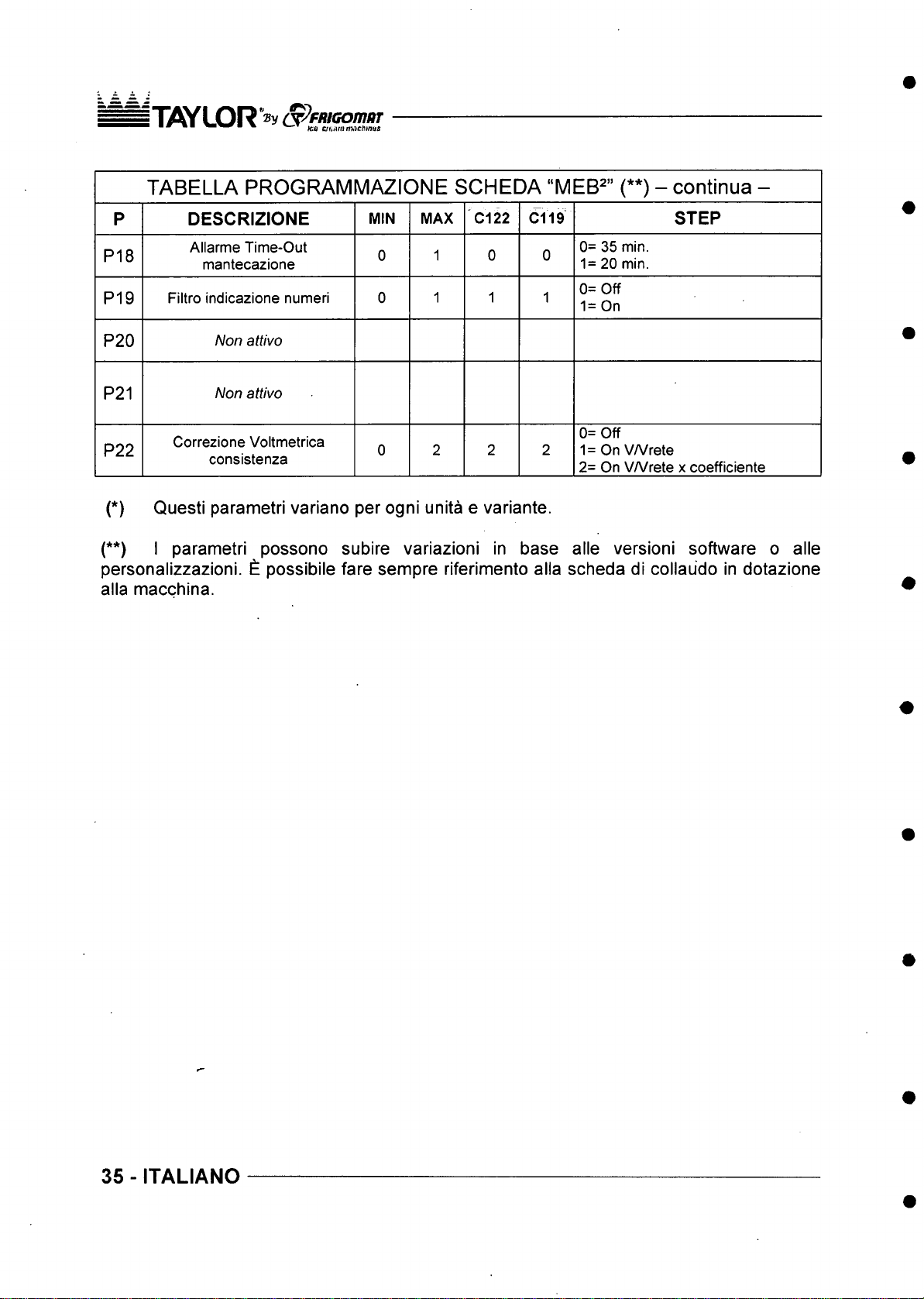
TABELLA PROGRAM M AZIO NE SCHEDA “MEB^” (**) - continua -
P
P18
P19
P20
P21
P22
DESCRIZIONE
Allarme Time-Out
mantecazione
Filtro indicazione numeri 0
MIN MAX
Non attivo
Non attivo
Correzione Voltmetrica
consistenza
0
0 2 2
C122
1 0 0
1
C119
1 1
STEP
0= 35 min.
1= 20 min.
0= Off
1= On
0= Off
2
1 = On VA/rete
2= On VA/rete x coefficiente
(*) Questi parametri variano per ogni unita e variante.
(**) I parametri possono subire variazioni in base alle versioni software o alle
personalizzazioni. £ possibile fare sempre riferimento alia scheda di collaudo in dotazione
alia macchina.
35 - ITALIANO
Page 37
n W L O R * » y S^ fR tG om a t
* \co iiTtfammacMnas
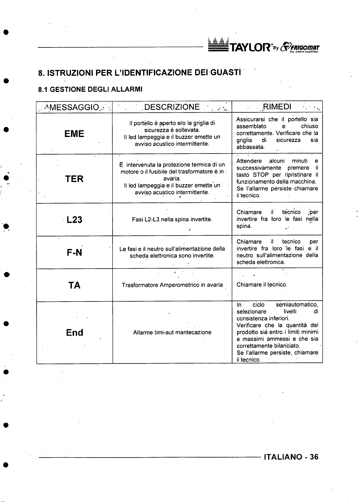
8. ISTRUZIONI PER L’IDENTIFICAZIONE DEI GUASTI
8.1 GESTIONE DEGLI ALLARMI
,, AMESSAGG\0^^ .
EME
TER
L23
F-N
DESCRIZIONE , . v
II portello e aperto e/o la griglia di
sicurezza e sollevata.
II led lampeggia e II buzzer emette un
avviso acustico intermittente.
£ intervenuta la protezione termica di un
motore o II fusibile del trasformatore e in^
avaria.
II led lampeggia e II buzzer emette un
avviso acustico intermittente.
Fasi L2-L3 nella spina invertite.
Le fasi e il neutro suH’alimentazione della
scheda elettronica sono irivertite.
*r
RIMEDI ■ ».
Assicurarsi che il portello sia
assemblato e chiuso
correttamente. Verificare che la
griglia di sicurezza sia
abbassata.
Attendere alcuni minuti e
successivamente premere il
tasto STOP per ripristinare il
funzionamento della niacchina.
Se I’allarme persiste-chiamare
il tecnico.
Chiamare il tecnico .-per
invertire fra loro le fasi nella
spina.
Chiamare il tecnico per
invertire fra loro 'le fasi e il
neutro sull’alimentazione della
scheda elettronica.
TA
End
Trasformatore Amperometrico in avaria
Allarme timi-aut mantecazione
Chiamare il tecnico.
In cicio semiautomatico,
selezionare livelli di
consistenza inferiori.
Verificare che la quantita del
prodotto sia entro i limitj minimi
e massimi ammessi e che sia
correttamente bilan'ciato.
Se I’allarme persiste, chiamare
il tecnico.
ITALIANO - 36
Page 38
n y v / L O R
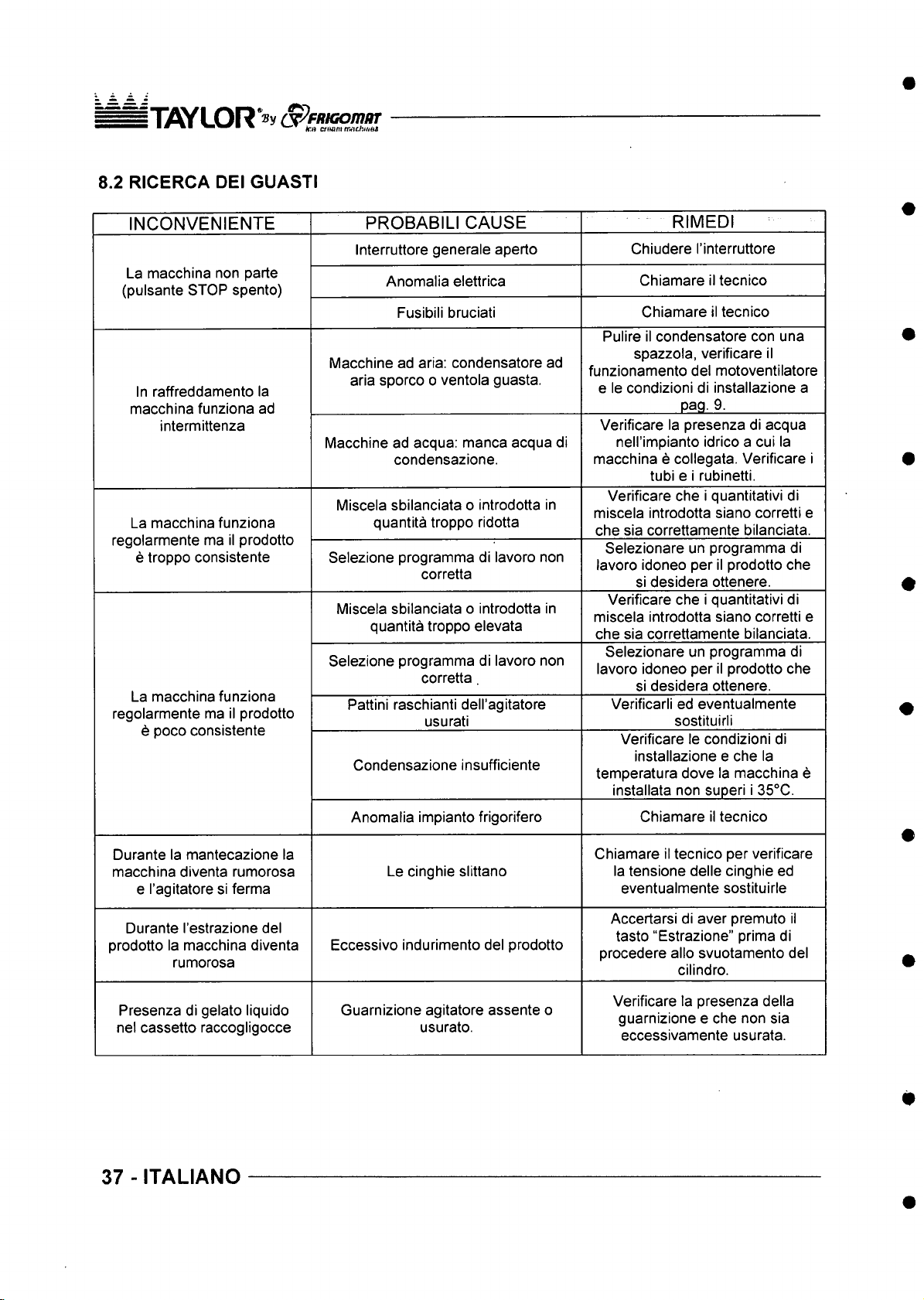
8.2 RICERCA DEI GUASTI
INCONVENIENTE
La macchina non parte
(pulsante STOP spento)
In raffreddamento la
macchina funziona ad
intermittenza
La macchina funziona
regolarmente ma il prodotto
e troppo consistente
La macchina funziona
regolarmente ma il prodotto
6 poco consistente
PROBABILI CAUSE
Interruttore generate aperto
Anomalia elettrica
Fusibili bruciati
Macchine ad aria: condensatore ad
aria sporco o ventola guasta.
Macchine ad acqua: manca acqua di
condensazione.
Miscela sbilanciata o introdotta in
quantita troppo ridotta
Selezione programma di lavoro non
corretta
Miscela sbilanciata o introdotta in
quantita troppo elevata
Selezione programma di lavoro non
corretta.
Pattini raschianti dell'agitatore
usurati
Condensazione insufficiente
RIMED!
Chiudere I’interruttore
Chiamare il tecnico
Chiamare il tecnico
Pulire il condensatore con una
spazzola, verificare il
funzionamento del motoventilatore
e le condizioni di installazione a
pag. 9.
Verificare la presenza di acqua
nell’impianto idrico a cui la
macchina e collegata. Verificare i
tubi e i rubinetti.
Verificare che i quantitativi di
miscela introdotta siano corretti e
che sia correttamente bilanciata.
Selezionare un programma di
lavoro idoneo per il prodotto che
si desidera ottenere.
Verificare che i quantitativi di
miscela introdotta siano corretti e
che sia correttamente bilanciata.
Selezionare un programma di
lavoro idoneo per il prodotto che
si desidera ottenere.
Verificarli ed eventualmente
sostituirli
Verificare le condizioni di
installazione e che la
temperatura dove la macchina e
installata non superi i 35°C.
Durante la mantecazione la
macchina diventa rumorosa
e I’agitatore si ferma
Durante I’estrazione del
prodotto la macchina diventa
rumorosa
Presenza di gelato liquido
nel cassetto raccogligocce
37 - ITALIANO
Anomalia impianto frigorifero
Le cinghie slittano
Eccessivo indurimento del prodotto
Guarnizione agitatore assente o
usurato.
Chiamare il tecnico
Chiamare il tecnico per verificare
la tensione delle cinghie ed
eventualmente sostituirle
Accertarsi di aver premuto il
tasto “Estrazione” prima di
procedere alio svuotamento del
cilindro.
Verificare la presenza della
guarnizione e che non sia
eccessivamente usurata.
Page 39
s T X ^ L O R S ^fftiG om /fT
• ^ V -.T hit ae im machh o a
Page 40
i"nflY LO R *® y (T ^fR iG om ftr
■ fc o C/BV)lir/7J>9C/fl«OS
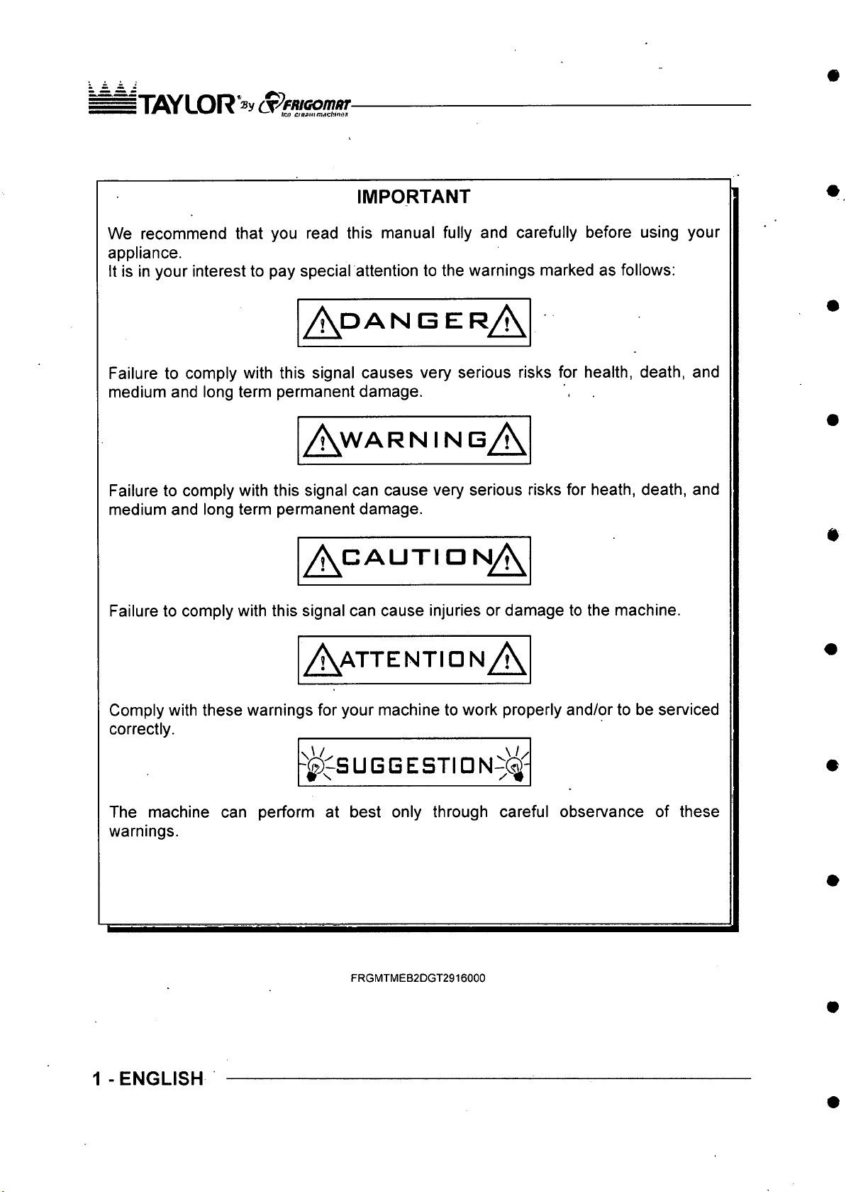
IMPORTANT
We recommend that you read this manual fully and carefully before using your
appliance.
It is in your interest to pay special attention to the warnings marked as follows:
/ \ d a n g e r A
Failure to comply with this signal causes very serious risks for health, death, and
medium and long term permanent damage.
A w ar ning A
Failure to comply with this signal can cause very serious risks for heath, death, and
medium and long term permanent damage.
A < ^ a u t i d n A
Failure to comply with this signal can cause injuries or damage to the machine.
A a t t en tid n A
Comply with these warnings for your machine to work properly and/or to be serviced
correctly.
h^^S U G G ES TI D N ^ C ^i
The machine can perform at best only through careful observance of these
warnings.
■ U /
1 - ENGLISH
FRGMTMEB2DGT2916000
Page 41
IliflYLOR »y opFftiGomiir
■ ^ fco avarna m c hlnas
We congratulate you for having chosen to purchase a TAYLOR machine.
This manual, supplied together with the machine, must be considered as an integral and
essential part of it and must be delivered .to the final user. Before carrying out any
operations, we recommend studying these instructions carefully.‘Only by reading them
carefully can you obtain the maximum performance frorri your machine. The following
pages carry all of the indications required to correctly. perforhri installatiori, operation,
adjustments and routine maintenance. tAYLOR reserves the right to carry out the
modifications it deems necessary to improve'its product or the technical manual without
prior warning, inserting the variations inThe subsequent editions. ,
Total and/or partial reproduction, adaptation or translations of this manual without prior
written consent by TAYLOR S.r.l is prohibited.
The machine is,covered by warranty according to the terms illustrated in the "WARRANTY
CARD" supplied. It must be properly filled in and returned to:
FRIGOMAT s.r.l., via 1® Maggio, 28 26862 GUARDAMIGLIO (LODI) - ITALY
Please write the serial number of your machine in the field below.
Serial number
Stamp of dealer
ENGLISH - 2
Page 42
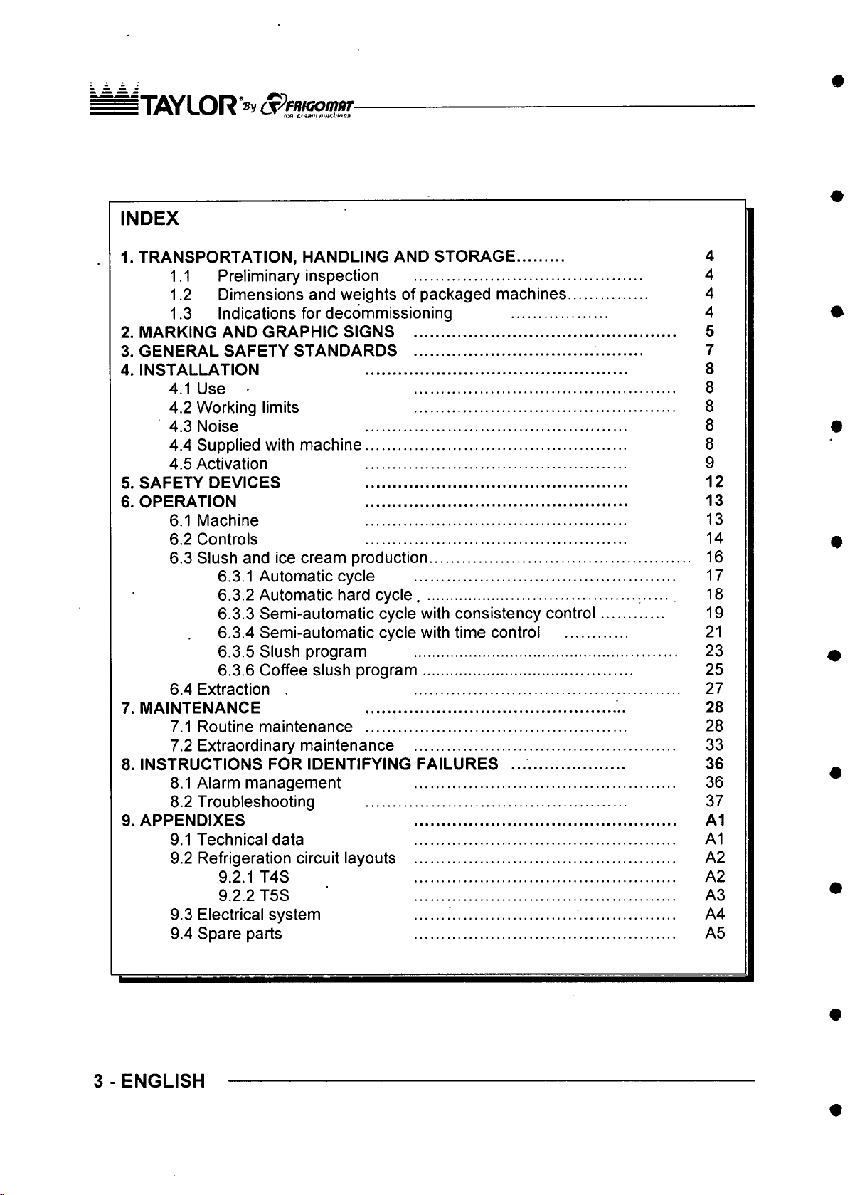
INDEX
1. TRANSPORTATION, HANDLING AND STORAGE
1.1 Preliminary inspection
1.2 Dimensions and weights of packaged machines.
1.3 Indications for decommissioning
2. MARKING AND GRAPHIC SIGNS ....................................
3. GENERAL SAFETY STANDARDS ....................................
4. INSTALLATION
4.1 Use •
4.2 Working limits
4.3 Noise ...............................................
4.4 Supplied with machine...............................................
4.5 Activation ...............................................
5. SAFETY DEVICES
6. OPERATION
6.1 Machine ...............................................
6.2 Controls ...............................................
6.3 Slush and ice cream production
6.3.1 Automatic cycle
6.3.2 Automatic hard cycle..................................................
6.3.3 Semi-automatic cycle with consistency control
6.3.4 Semi-automatic cycle with time control
6.3.5 Slush program ............................................................
6.3.6 Coffee slush program................................................
6.4 Extraction .
7. MAINTENANCE
7.1 Routine maintenance
7.2 Extraordinary maintenance
8. INSTRUCTIONS FOR IDENTIFYING FAILURES ..........................
8.1 Alarm management
8.2 Troubleshooting
9. APPENDIXES ............................................................
9.1 Technical data
9.2 Refrigeration circuit layouts
9.2.1 T4S A2
9.2.2 T5S A3
9.3 Electrical system A4
9.4 Spare parts A5
...............................................
...............................................
...............................................
.........................................................
...........................................................
...........................................................
...................................
...................................
...................................
...........................................................
...........................................................
............................................................
...........................................................
...........................................................
...........................................................
...........................................................
..........
.............
..............
..............
...........
...........
...........
...........
..........
.....
.........
............
............. 27
...........
...........
...........
...........
4
4
4
4
5
7
8
8
8
8
8
9
12
13
13
14
16
17
18
19
21
23
25
28
28
33
36
36
37
A1
A1
A2
3 - ENGLISH
Page 43
I TOY LOR* ®v S ^f/tiG om /ir
• * * ■ m V.-<T ^ f/o a m n'aehinn<
1 TRANSPORTATION, HANDLING AND STORAGE.
1.1 PRELIMINARY INSPECTION AND STORAGE
The machine is transported at the risk and peril of the customer. If you notice any damage
to the packaging, immediately inform the carrier.
Inform the carrier right after opening the package if the machine is damaged even if it is a
few days after delivery.
It is always preferable to accept goods SUBJECT TO CLEARANCE.
The appliance must be handled with care; it can be damaged by falls and blows even
without exterior damages.
Storage temperature must be between 0° and + 50°C, and humidity between 30 and 95%
with no dew.
Once the appliance has been unpacked, the packaging must be kept in a dry place out of
the reach of children. If stored properly, it can be reused if the machine is moved.
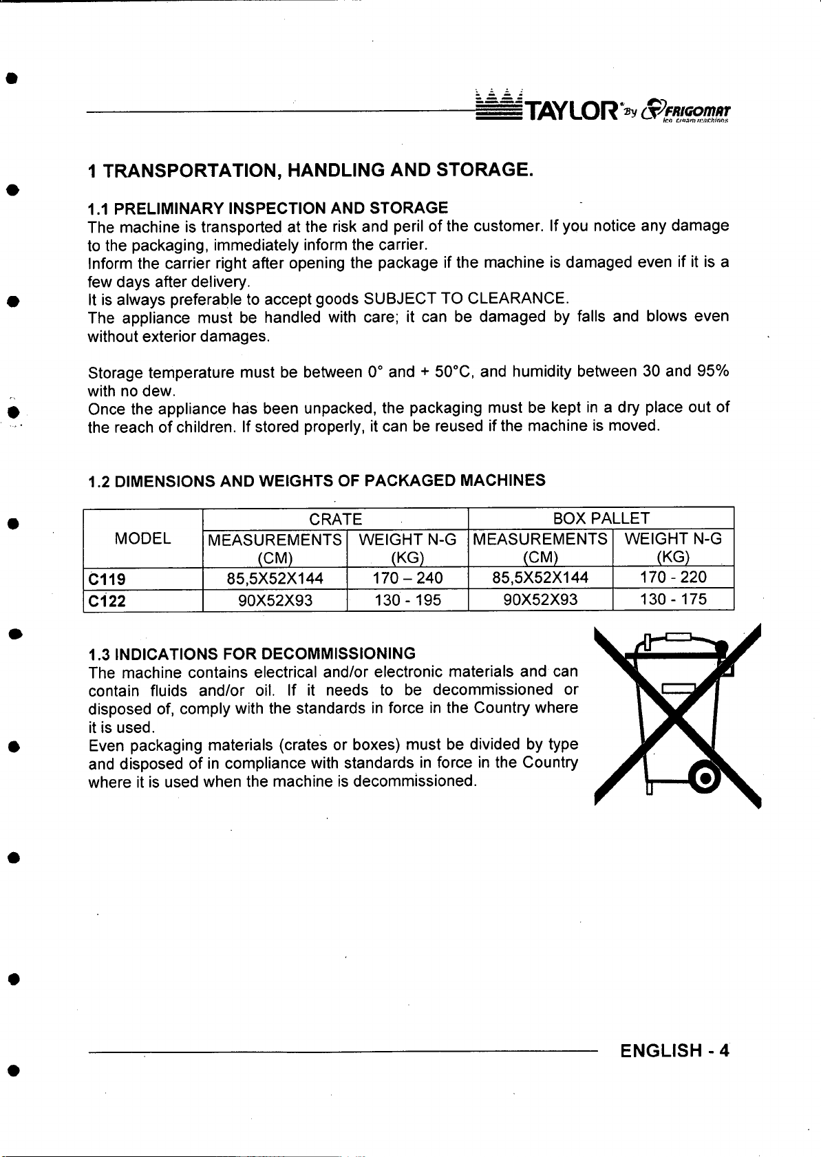
1.2 DIMENSIONS AND WEIGHTS OF PACKAGED MACHINES
CRATE
MODEL
C119
Cl 22
1.3 INDICATIONS FOR DECOMMISSIONING
The machine contains electrical and/or electronic materials and can
contain fluids and/or oil. If it needs to be decommissioned or
disposed of, comply with the standards in force in the Country where
it is used.
Even packaging materials (crates or boxes) must be divided by type
and disposed of in compliance with standards in force in the Country
where it is used when the machine is decommissioned.
MEASUREMENTS
(CM)
85,5X52X144
90X52X93
WEIGHT N-G
(KG)
170-240
130-195
MEASUREMENTS
85,5X52X144
90X52X93
BOX PALLET
(CM)
WEIGHT N-G
(KG)
170-220
130-175
ENGLISH - 4
Page 44
nyS YLOR "® v S ^F/tK o m ^ r
• * ^ rim rJu tw s
2. MARKING AND GRAPHIC SIGNS
The machine is provided with an identification plate and some pictograms. They must be
known along with the manual to guarantee safe use.
C D ^
P X VA .
M o d .
C o d .
VU 1’ Maogb >20B U • rTAUA T «l.0372 4tS OI1
M eU .
S e rt e
Hz
A . IP C L 1R .
C€
i ©
]
Machine data plate
The adhesive plate applied on the rear enables to
identify the model. It includes the following indications;
Name and address of the manufacturer; machine
model and version; serial number; nominal electrical
K W
features; type and weight of gas used; year of
K g
manufacture.
Indication
Lifting e qu ip m en t h ook ing points:
This plate indicates the points where the lifting hooks
must be placed to carry out this operation safely. Use
a Phillips screwdriver to unscrew the two side panels
of the machine and position the lifting equipment in
the relevant points, making sure that they cannot
accidentally slip off during lifting operations.
Attention!
M ain ten an ce reserv ed fo r qu alified pe rs onnel. This
plate applied on the rear panel prohibits extraordinary
maintenance and/or repairs to anyone but authorised
personnel, whose address is indicated in the space
provided.
5 - ENGLISH
Attention!
Do not touch with yo ur hands.
This plate applied on the rear panel of machines with
air cooling indicates that the heat exchanger can only
be cleaned using a brush or vacuum cleaner.
Page 45
n iflJ /L O R S ^ fn id o m a r
■ ■ m tuoom mnehiiMS
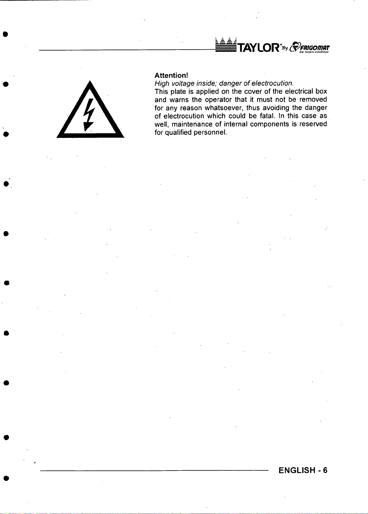
Attention!
High vo ltage inside; d ang er o f electrocution.
This plate is applied on the cover of the electrical box
and warns the operator that it must not be removed
for any reason whatsoever, thus avoiding the danger
of electrocution which could be fatal. In this case as
well, maintenance of internal components is reserved
for qualified personnel.
ENGLISH -6
Page 46
IT A YL O R
3. GENERAL SAFETY STANDARDS
/ \ d a n g e r A
Strictly observe the general safety and accident-prevention standards listed hereafter;
- Use of the machine is reserved for personnel in good health, responsible and
appropriately trained as to allowed use and risks present.
- Use of the machine is reserved for operators who have read, understood and taken
in all that is included in this manual.
- It is forbidden to remove or tamper with the safety systems installed on the
machine.
- While the appliance is operating, it is mandatory to check that danger situations for
persons do not occur. Should these conditions occur, stop the appliance
immediately.
- When you have finished working with the machine, it is mandatory to cut power by
acting on the master switch.
- When unusual noise or anomalous functioning is perceived, it is mandatory to
immediately stop operations in progress and to search for the cause of these
irregularities. If in doubt, avoid improper operations by contacting the technical
assistance service of the manufacturer.
- Any tampering or modification of the machine automatically entails the immediate
termination of the warranty and relieves the manufacturer of all and any liability for
direct or indirect damage caused.
- It is mandatory to check that the place where the machine is installed is ventilated
and correctly illuminated. The surface where the appliance is installed must be
solid, flat and levelled.
- During loading, unloading and handling operations, it is mandatory to use
equipment with a capacity adequate for the mass (weight) of the machine, using
hoisting devices and accessories with features and state of use suitable for the
purpose.
- Use only original TAYLOR spare parts when performing maintenance. The
manufacturer will not be held liable for damage caused by use of non-original spare
parts. Use of non-original spare parts entails automatic termination of the warranty.
- It is mandatory to position the machine far away from equipment which emits
electromagnetic radiation which could cause the circuit boards to malfunction.
- If fire-prevention equipment needs to be used, use types which are compatible with
the presence of voltage on board.
- It is forbidden to wear long and loose apparel, ties, jewellery, scarves or similar
clothing which could get caught in the moving parts of the machine.
- Hair must be tied and shirt-sleeves tight.
7 - ENGLISH
Page 47
^ T flY L O R »y S ^Fm co m sT
4. INSTALLATION
4.1 USE
Appliance suitable for batch freezing of ice cream mixtures and slush production,
according to use allowed by Law.
4.2 WORKING LIMITS
Do not use the machine with inconstant power supplies or +/- 10% beyond the value
indicated on the plate or with the power cable damaged;
Do not use the machine in explosive atmospheres;
Do not wash the machine with high-pressure water jets or with harmful substances;
Do not expose the machine to excessive heat or humidity;
Do not use unbalanced mixtures and/or amounts which do not comply with the
specifications carried on the packs.
A w ar ningA
Use not expressly indicated in this manual is to be considered improper and therefore
must be strictly avoided.
The manufacturer will not be held liable for direct or indirect harm to persons or animals or
damage to objects caused by improper use of the machine.
4.3 NOISE
SOUND EMISSION LEVEL EXPRESSED IN DECIBELS (measurement method A)
As foreseen by Machinery Directive 89/392 standard EN 23741
(A-weighted equivalent continuous sound pressure level)
V ' LEVEL (A) -
< = 68 dB (A)
C119
MODEL
LEVEL(A)
< = 68 dB (A)
A ; .MODEL ‘ ;
C122
4.4 SUPPLIED WITH MACHINE
- Ice cream extraction spatula
- Complete scrapers
- Centring pin for beater
- Brush
- Gasket extractor
Rubber Seal
Lubricant
Use and maintenance manual
Declaration of conformity
Warranty certificate
- 0-ring kit
ENGLISH - 8
Page 48
n7SY LO R "»y S^FHiG om iiT
4.5 ACTIVATION
A w ar n ingA
TAYLOR declines all and any liability for damage caused by failure to comply with the
following indications. This lack of compliance causes the warranty to terminate.
Connection of the machine to the water mains must be performed respecting national
regulations of the Country where the machine is installed.
To commission the machine, bring it to the place of use, checking what is requested for its
installation;
1. Electrical power supply 3 phases + neutral + earth (5 wires - only three-phase
mod.)
Electrical power supply 2 phases + earth (3 wires - only single-phase mod.);
2. Cold water mains supply (13° - 20°C, only water mod.);
3. Condensation water drain (only water mod.).
• Make sure the appliance is positioned on a solid, stable, flat and levelled surface.
• Block the machine by acting on the relevant brake lever on the front wheels (C119
only).
• Leave at least 10 cm from the side panels and 30 cm from the rear panel between the
machine and the walls or other obstacles. For machines with water condensation, the
distance between the wall and the rear panel must be 10 cm.
• Check the exact correspondence between the voltage and power of the mains
compared to the values carried on the data plate applied on the rear panel;
• Connect the machine to the electrical power supply system. Install a omnipolar master
switch upstream the appliance with minimum contact opening of 3 mm of adequate
power, with a fuse and circuit breaker protective system. Use an approved interlocking
plug to allow only the open circuit to connect and disconnect.
• The cable must be well laid, without being rolled-up or overlapped. It must not be
exposed to blows or tampering. It must not be in the vicinity of liquids or water and heat
sources. It must not be damaged in any way. If so, before connecting the machine to
the mains, have it replaced by qualified personnel with another having a 5G4 H07RN-F
(400 V version), 5G6 H07RN-F (220 V / 3 version) cross-section.
• For safety purposes, make sure the earthing system to which the machine plug is
connected is compliant with standards and perfectly efficient.
9 -ENGLISH
Page 49

IWUDR "sy
If needed, carry out an equipotential bonding,
using the screw placed on the rear of the machine
below the frame and marked with the symbol
shown to the left.
Make sure that the cold water supply line intended
for condensation has pressure values between 1
and 3 BAR and temperature between 13° and
20°C.
Connect the cold water supply pipe intended for
condensation onto the machine inlet as shown in
the figure. Use a 01/2" fitting and place a gate
valve in the operator's reach.
Connect the condensation water drain pipe onto
the machine outlet as shown in the figure, using a
01/2” fitting.
Always use new pipes suitable for hot water and
for pressure up to 10 bars both for delivery and
draining. Never use worn or consumed piping. Use
suitable DIN 3017 hose clamps.
The drain pipe must have an inclination of at least
3 cm for each meter of length.
After having connected the water inlet and outlet
pipes, with the machine stopped, open the cut-off
cock and make sure that water does not leak from
the drain.
Turn off the master switch and press the
PRODUCTION button to check the following:
1. Beater motor rotation direction {three-phase
models only).
The machine is equipped with a sophisticated
electronic system which is able to automatically
detect if the beater motor rotation direction is
the correct one (anti-clockwise).
If the phases are inverted in the plug, after a
few seconds of operating in production mode,
the machine stops and the display shows the
F23 alarm. To connect the phases properly cut
the power and invert the two phase wires in the
plug.
ENGLISH-10
Page 50

iT /C /L O R "» y
Condensation pressure (water models
2.
only).
With the machine in production mode, after a
few seconds condensation water must come
out of the drain pipe at a temperature of about
35®C. If this is not the case, the pressure switch
valve shown in the figure must be adjusted.
A c a u t i □ n/ \
Three-phase machines are powered with three-
phase + neutral lines: be careful never to
connect the phase lines with neutral. TAYLOR
will not be held liable for damage to the
machine deriving from incompliance with this
rule.
Press the STOP button to stop the machine .
Operating temperature should be between 15“ and 35“C.
Humidity should be between 30 and 60%.
/ \ d a n g e r A
TAYLOR will not be held liable for personal harm and/or damage to objects deriving from
incorrect installation and/or by failure to comply with work accident-prevention standards.
Never intervene on the machine with your hands, neither during normal operating cycles
nor during cleaning and maintenance, without first having stopped the machine by
pressing the STOP button and having turned off the master switch. Never clean the
appliance using a high-pressure water jet. Never shut the water cut-off cock while the
machine is running. Be careful never to damage the power cable. If so, have it replaced.
Machines with water cooling which are left in places at a temperature below or close to
0“C, must first have all the water drained from the condenser.
11 - ENGLISH
Page 51

IWUDR " »y (X^FRIGO/n/IT
5. SAFETY DEVICES
Shearing-prevention safety device: Implemented by means of a safety circuit compliant
with the European directive, it intervenes when the door is opened and/or when the safety
grid on the hopper is lifted, temporarily switching the machine to STOP mode.
Beater motor overheating safety device: Implemented by means of a thermal relay; it
protects the machine beater motor operation from overloads, by signalling the relative
alarm message on the display, emitting an intermittent acoustic signal and enabling to
reset directly from the push button control panel.
Semi-hermetic compressor motor overheating safety device: Implemented by means
of an automatic reset thermal relay; it protects the machine compressor motor operation
from overloads, by signalling the relative alarm message on the display, emitting an
intermittent acoustic signal and enabling to reset directly from the push button control
panel.
Hermetic compressor motor overheating safety device: Implemented by means of an
automatic reset thermal-current sensor: it protects the machine compressor motor
operation from overloads. The protection device intervention determines the temporary
stop of the compressor motor only.
Refrigeration circuit over-pressure safety device: Implemented by means of the
approved automatic-reset safety pressure switch; it protects the integrity of the
refrigeration circuit from over-pressure. The protection device intervention determines the
temporary stop of the compressor motor only.
Protection against short circuit of auxiliary utilities: Implemented by fuses which
intervene on the logic unit or auxiliary power supply in the event of short-circuits.
SELV safety circuit: the push button control panel is powered at low voltage by means of
an approved dual-insulation safety transformer, protected against short circuits by fuses.
ENGLISH -12
Page 52

^ = T A Y L O R >
6. OPERATION
6.1 MACHINE
1. Door
Closes the cylinder hermetically during the
processing phases. It can be easily removed for
cleaning.
2. Safety grid - hopper cover
Allows the operator to load the product safely.
The cover keeps the mixture from coming into
contact with dust.
3. Door blocking handle (C119)
Seals the door with the lever lowered. To open,
ensure that all the product has come out and that
the machine is in STOP mode, then pull the lever
upwards to unblock the door and rotate it
outwards.
4. Door blocking knobs (Cl 22)
Close the door hermetically. To open, ensure that
all the product has come out and that the machine
is in STOP mode, then rotate the two knobs
outwards to unblock the door, pull the lower part of
the door outwards acting on the handle of the
dispenser door.
5. Control panel
Enables to select the work programs.
6. Dispenser disk
Used when extracting ice cream and emptying
water to clean the cylinder. It is unblocked by
5
1
rotating it to the right (C119) or to the left (Cl 22).
7. Drip drawer
Collects leakage of liquid from the cylinder gland
follower.
8. Electrical box
9. Water / electrical power inputs
13-ENGLISH
Page 53
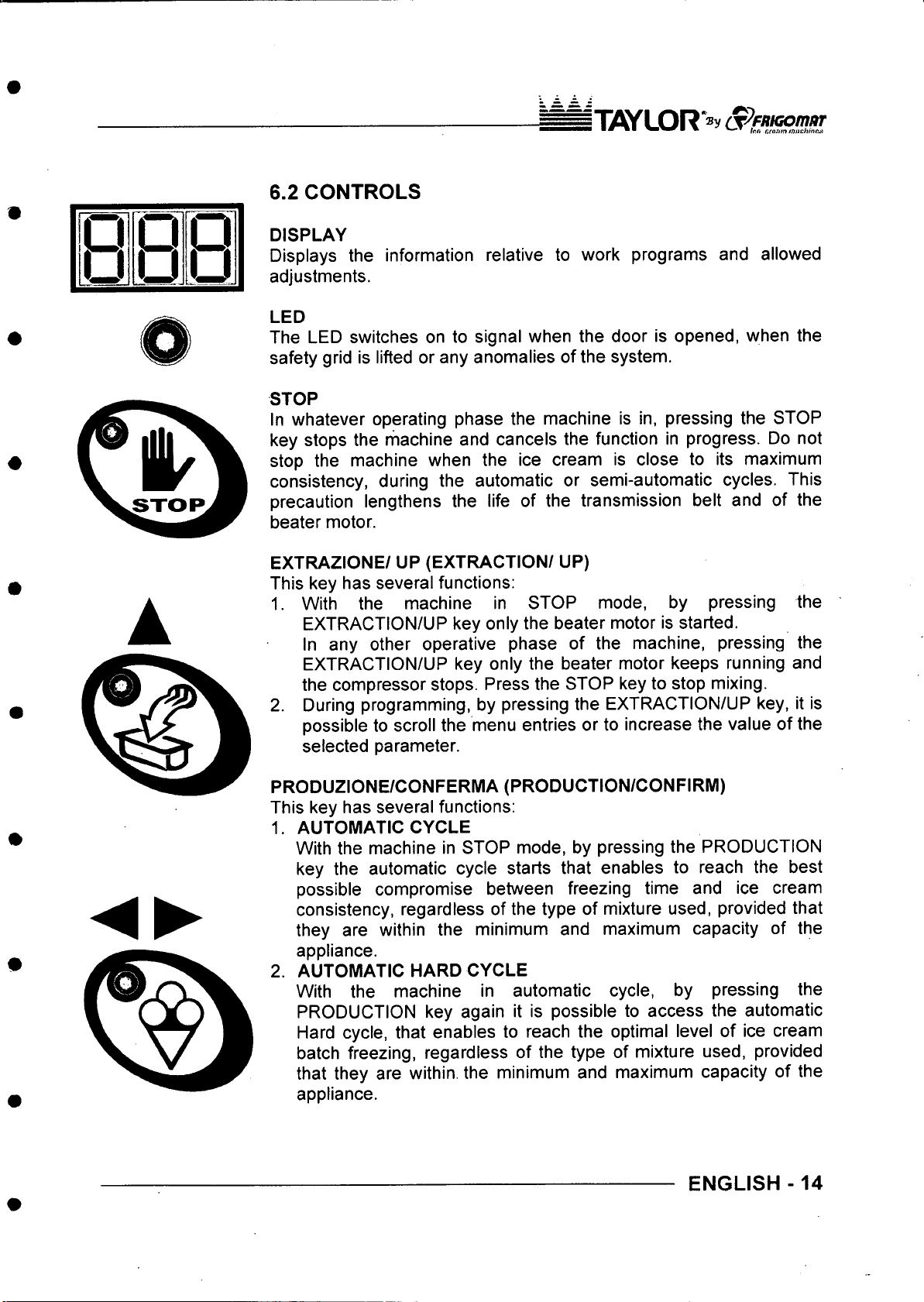
6.2 CONTROLS
j1 iflY L O R“®y (S^ fM G o m a r
■ ■ * * ■ m m w « * ttaum m a c h in e
O O P
D
U U
DISPLAY
Displays the information relative to work programs and allowed
adjustments.
LED
The LED switches on to signal when the door is opened, when the
safety grid is lifted or any anomalies of the system.
STOP
In whatever operating phase the machine is in, pressing the STOP
key stops the machine and cancels the function in progress. Do not
stop the machine when the ice cream is close to its maximum
consistency, during the automatic or semi-automatic cycles. This
precaution lengthens the life of the transmission belt and of the
beater motor.
EXTRAZIONE/ UP (EXTRACTION/ UP)
This key has several functions:
1. With the machine in STOP mode, by pressing
EXTRACTION/UP key only the beater motor is started.
In any other operative phase of the machine, pressing the
EXTRACTION/UP key only the beater motor keeps running and
the compressor stops. Press the STOP key to stop mixing.
2. During programming, by pressing the EXTRACTION/UP key, it is
possible to scroll the menu entries or to increase the value of the
selected parameter.
the
PRODUZIONE/CONFERMA(PRODUCTION/CONFIRM)
This key has several functions:
1. AUTOMATIC CYCLE
With the machine in STOP mode, by pressing the PRODUCTION
key the automatic cycle starts that enables to reach the best
possible compromise between freezing time and ice cream
consistency, regardless of the type of mixture used, provided that
they are within the minimum and maximum capacity of the
appliance.
2. AUTOMATIC HARD CYCLE
With the machine in automatic cycle, by pressing the
PRODUCTION key again it is possible to access the automatic
Hard cycle, that enables to reach the optimal level of ice cream
batch freezing, regardless of the type of mixture used, provided
that they are within, the minimum and maximum capacity of the
appliance.
ENGLISH-14
Page 54
ITAYLOR
SEMI-AUTOMATIC CYCLE with consistency control.
With the machine in automatic Hard cycle, by pressing the
PRODUCTION key again it is possible to access the semi
automatic cycle with consistency control that enables the operator
to manually select the level of consistency one wishes to achieve.
During programming, pressing the PRODUCTION/CONFIRM key
4.
confirms the selection of the menu entry or the value of the
selected parameter.
SEMI-AUTOMATIC TIME/DOWN CYCLE
This key has several functions:
1. SEMI-AUTOMATIC CYCLE with time control.
With the machine in STOP mode, by pressing the SEMI
AUTOMATIC TIME/DOWN CYCLE key it is possible to access
the batch freezing time control, which enables the operator to
manually select the processing time of the mixture.
2. During programming, by pressing the SEMI-AUTOMATIC
TIME/DOWN CYCLE key it is possible to scroll the menu entries
or to reduce the value of the selected parameter.
SLUSH PRODUCTION
With the machine in STOP mode, by pressing the SLUSH
PRODUCTION key one enables the GR1 programs with consistency
control and continuous mixing, and GR2 with time control and cyclic
mixing.
15-ENGLISH
Page 55
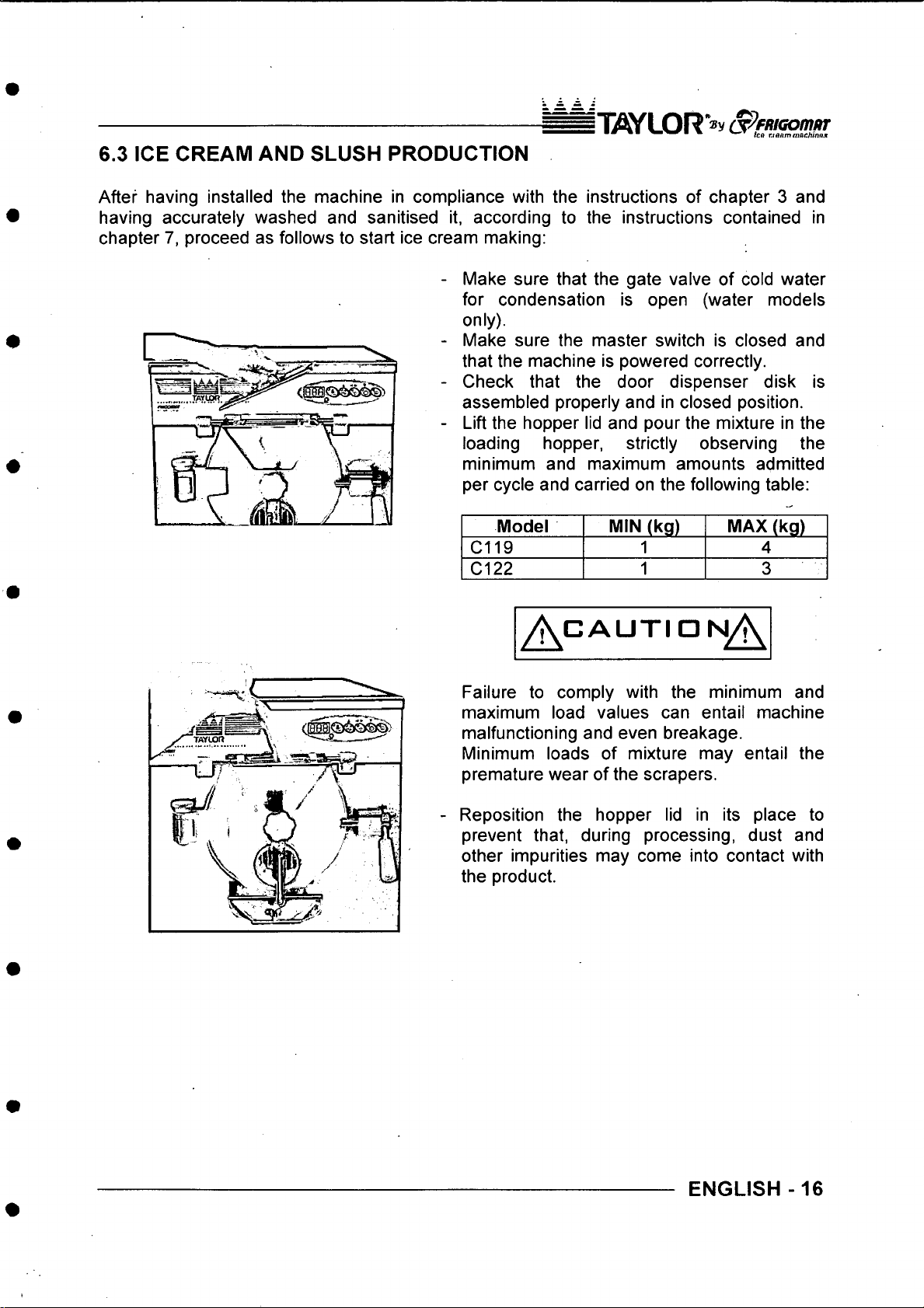
IT if iY LO R ®v S^FRiGomar
■ ^ ten rianmnjac/7*nfl.»
6.3 ICE CREAM AND SLUSH PRODUCTION
After having installed the machine in compliance with the instructions of chapter 3 and
having accurately washed and sanitised it, according to the instructions contained in
chapter 7, proceed as follows to start ice cream making:
- Make sure that the gate valve of cold water
for condensation is open (water models
only).
- Make sure the master switch is closed and
that the machine is powered correctly.
- Check that the door dispenser disk is
assembled properly and in closed position.
- Lift the hopper lid and pour the mixture in the
loading hopper, strictly observing the
minimum and maximum amounts admitted
per cycle and carried on the following table:
Model MIN (kg) MAX (kg)
C119
C122
1 4
1 3
A CA U T I O N ^
Failure to comply with the minimum and
maximum load values can entail machine
malfunctioning and even breakage.
Minimum loads of mixture may entail the
premature wear of the scrapers.
Reposition the hopper lid in its place to
prevent that, during processing, dust and
other impurities may come into contact with
the product.
ENGLISH -16
Page 56
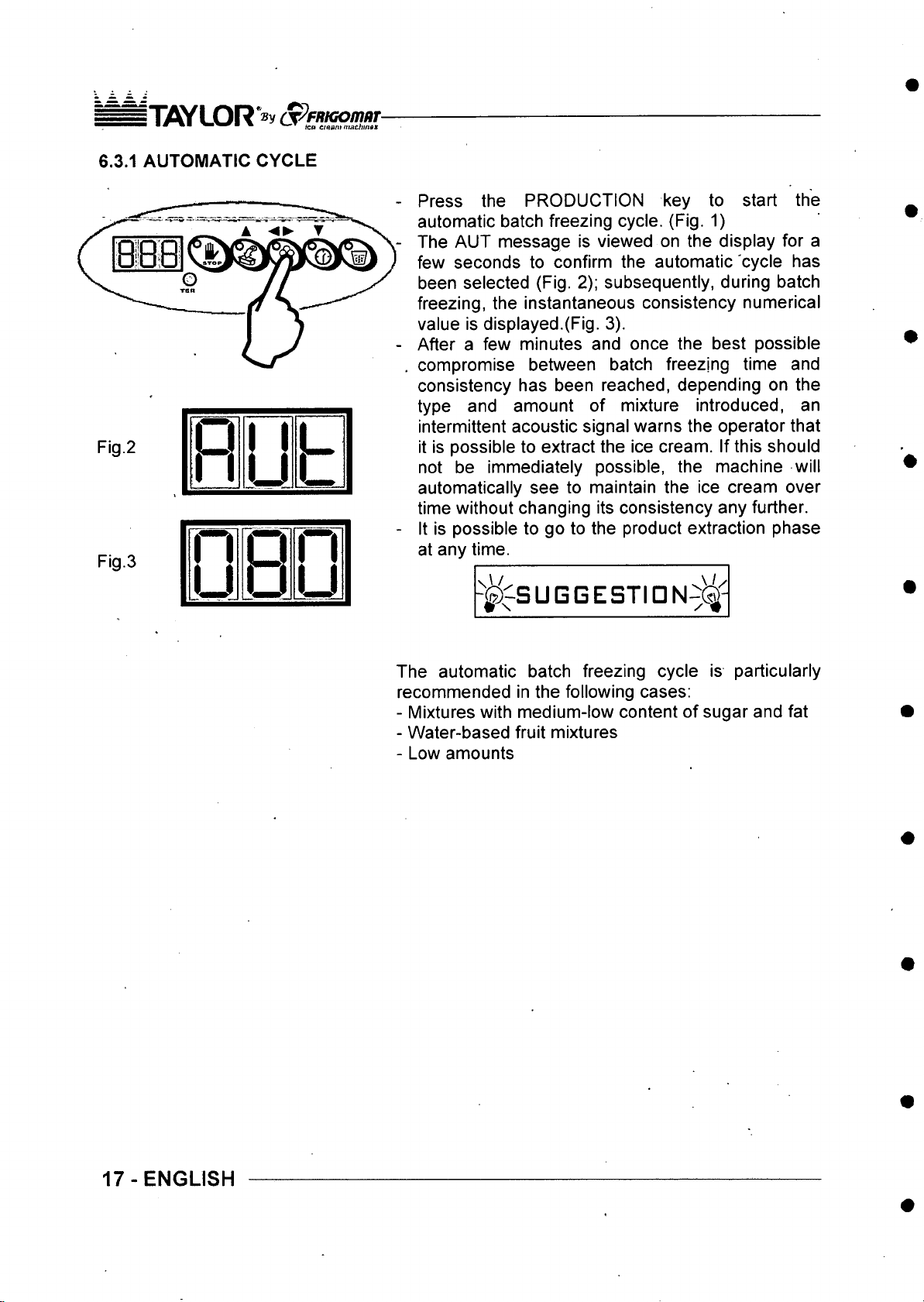
|"n flY LO R *®y (^FR iG om iir
■ m m » ■ ■ m ic a et fi ent n t a c im »n
6.3.1 AUTOMATIC CYCLE
Fig.2
Fig.3
n
11
n
u a
1
u
p
L
u
Press the PRODUCTION key to start the
automatic batch freezing cycle. (Fig. 1)
The AUT message is viewed on the display for a
few seconds to confirm the automatic cycle has
been selected (Fig. 2); subsequently, during batch
freezing, the instantaneous consistency numerical
value is displayed.(Fig. 3).
After a few minutes and once the best possible
compromise between batch freezing time and
consistency has been reached, depending on the
type and amount of mixture introduced, an
intermittent acoustic signal warns the operator that
it is possible to extract the ice cream. If this should
not be immediately possible, the machine will
automatically see to maintain the ice cream over
time without changing its consistency any further.
It is possible to go to the product extraction phase
at any time.
- ^ S U G G E S T ID N ^ ^
The automatic batch freezing cycle is particularly
recommended in the following cases;
- Mixtures with medium-low content of sugar and fat
- Water-based fruit mixtures
- Low amounts
17-ENGLISH
Page 57
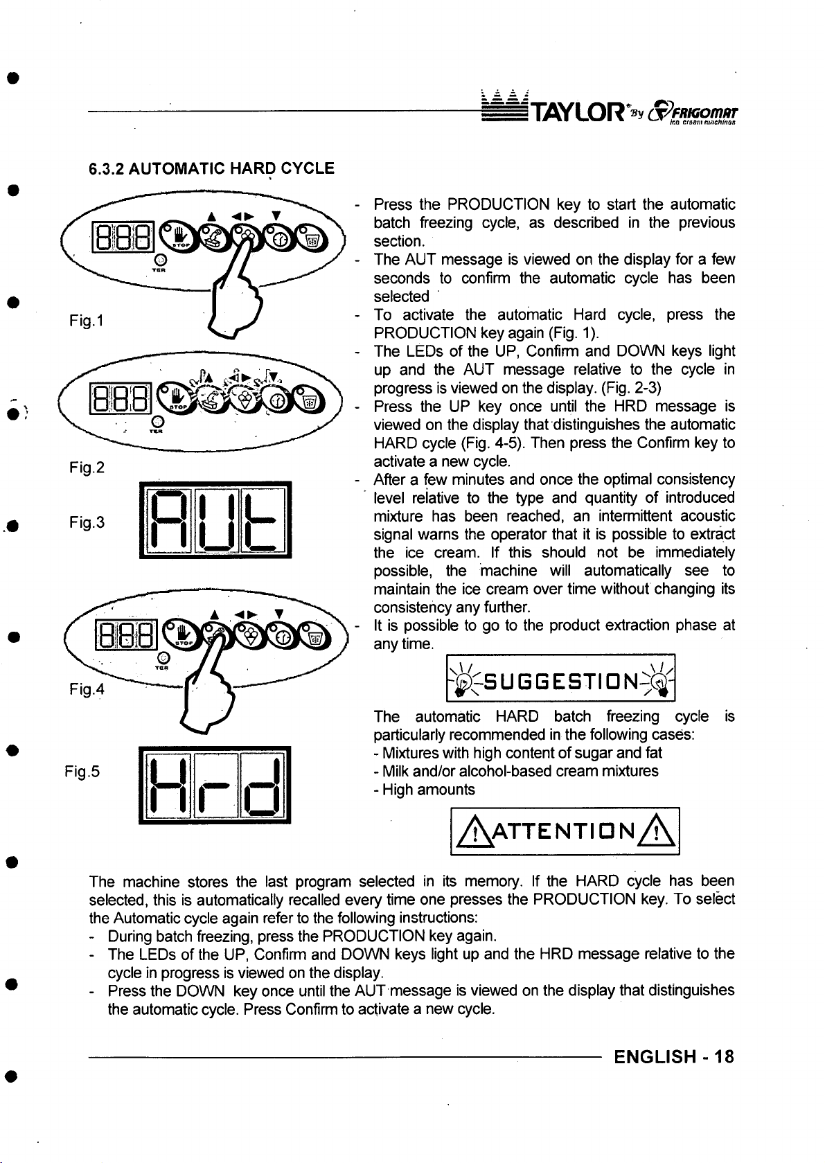
6.3.2 AUTOMATIC HARD CYCLE
Fig.2
Fig.3
□
h
u
b
j1iflyL O R *® V (y?F/tK!Om iiT
■ m V - .T ir.o emsiiifuacJUnos
Press the PRODUCTION key to start the automatic
batch freezing cycle, as described in the previous
section.
The AUT message is viewed on the display for a few
seconds to confirm the automatic cycle has been
selected
To activate the automatic Hard cycle, press the
PRODUCTION key again (Fig. 1).
The LEDs of the UP, Confirm and DOWN keys light
up and the AUT message relative to the cycle in
progress is viewed on the display. (Fig. 2-3)
Press the UP key once until the HRD message is
viewed on the display that distinguishes the automatic
HARD cycle (Fig. 4-5). Then press the Confirm key to
activate a new cycle.
After a few minutes and once the optimal consistency
level relative to the type and quantity of introduced
mixture has been reached, an intermittent acoustic
signal warns the operator that it is possible to extract
the ice cream. If this should not be immediately
possible, the machine will automatically see to
maintain the ice cream over time without changing its
consistency any further.
It is possible to go to the product extraction phase at
any time.
___________________
- j^^S U G G E S T I O N ^ ^ -
The automatic HARD batch freezing cycle
particularly recommended in the following cases:
- Mixtures with high content of sugar and fat
Fig.5
u
h f
□
- Milk and/or alcohol-based cream mixtures
- High amounts
A a t ten t iq n A
The machine stores the last program selected in its memory. If the HARD cycle has been
selected, this is automatically recalled every time one presses the PRODUCTION key. To select
the Automatic cycle again refer to the following instructions:
- During batch freezing, press the PRODUCTION key again.
- The LEDs of the UP, Confirm and DOWN keys light up and the HRD message relative to the
cycle in progress is viewed on the display.
- Press the DOWN key once until the AUT message is viewed on the display that distinguishes
the automatic cycle. Press Confirm to activate a new cycle.
ENGLISH-18
IS
Page 58
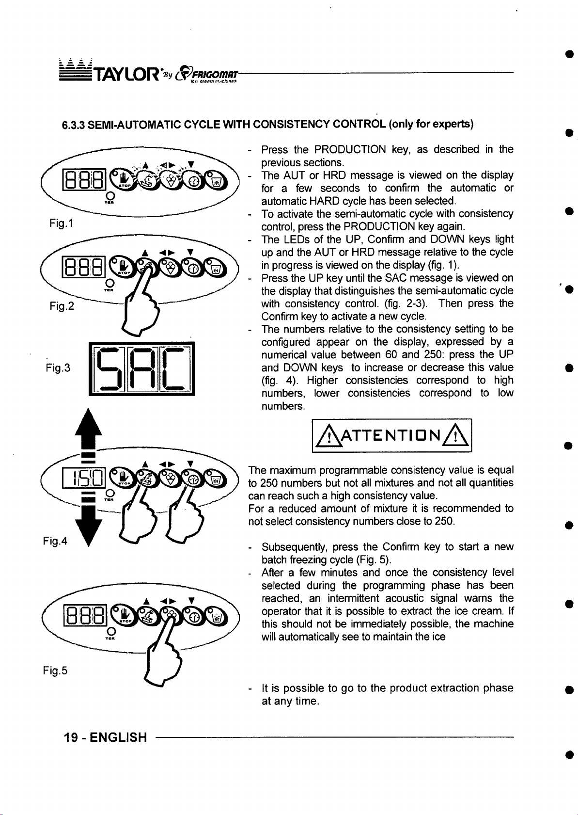
n7S Y LO R*®y S ^ m a o n m
■ ■ m -w.* ten eiBmnnurJ\me^
6.3.3 SEMI-AUTOMATIC CYCLE WITH CONSISTENCY CONTROL (only for experts)
Press the PRODUCTION key, as described in the
previous sections.
The AUT or HRD message is viewed on the display
for a few seconds to confirm the automatic or
automatic HARD cycle has been selected.
To activate the semi-automatic cycle with consistency
control, press the PRODUCTION key again.
The LEDs of the UP, Confirm and DOWN keys light
up and the AUT or HRD message relative to the cycle
in progress is viewed on the display (fig. 1).
Press the UP key until the SAC message is viewed on
the display that distinguishes the semi-automatic cycle
with consistency control, (fig. 2-3). Then press the
Confirm key to activate a new cycle.
The numbers relative to the consistency setting to be
configured appear on the display, expressed by a
numerical value between 60 and 250: press the UP
Fig.3
SH
and DOWN keys to increase or decrease this value
(fig. 4). Higher consistencies correspond to high
numbers, lower consistencies correspond to low
numbers.
Fig.4
A a t t e n t id n A
The maximum programmable consistency value is equal
to 250 numbers but not all mixtures and not all quantities
can reach such a high consistency value.
For a reduced amount of mixture it is recommended to
not select consistency numbers close to 250.
- Subsequently, press the Confirm key to start a new
batch freezing cycle (Fig. 5).
- After a few minutes and once the consistency level
selected during the programming phase has been
reached, an intermittent acoustic signal warns the
operator that it is possible to extract the ice cream. If
this should not be immediately possible, the machine
will automatically see to maintain the ice
- It is possible to go to the product extraction phase
at any time.
19-ENGLISH
Page 59
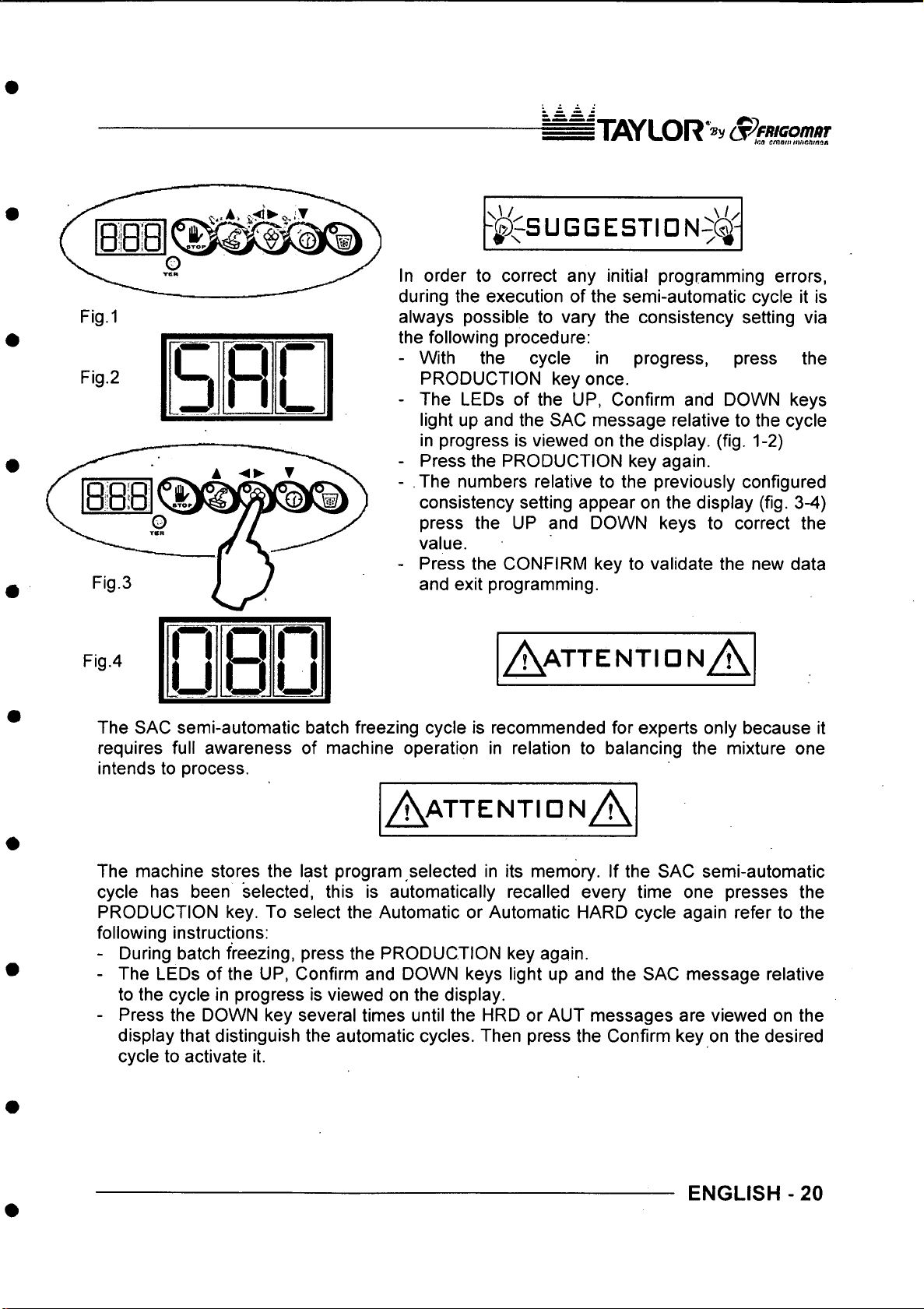
niWLOR*®y
- j ^ ^S U G G E S TI D N ^^ -
In order to correct any initial programming errors,
during the execution of the semi-automatic cycle it is
always possible to vary the consistency setting via
the following procedure:
- With the cycle in progress, press the
PRODUCTION key once.
- The LEDs of the UP, Confirm and DOWN keys
light up and the SAC message relative to the cycle
in progress is viewed on the display, (fig. 1-2)
- Press the PRODUCTION key again.
- The numbers relative to the previously configured
consistency setting appear on the display (fig. 3-4)
press the UP and DOWN keys to correct the
value.
- Press the CONFIRM key to validate the new data
and exit programming.
Fig.4
The SAC semi-automatic batch freezing cycle is recommended for experts only because it
requires full awareness of machine operation in relation to balancing the mixture one
intends to process.
I I
u
8
A atten tio nA
ij
A attentidn A
The machine stores the last program selected in its memory. If the SAC semi-automatic
cycle has been selected, this is automatically recalled every time one presses the
PRODUCTION key. To select the Automatic or Automatic HARD cycle again refer to the
following instructions:
- During batch freezing, press the PRODUCTION key again.
- The LEDs of the UP, Confirm and DOWN keys light up and the SAC message relative
to the cycle in progress is viewed on the display.
- Press the DOWN key several times until the HRD or AUT messages are viewed on the
display that distinguish the automatic cycles. Then press the Confirm key on the desired
cycle to activate it.
ENGLISH - 20
Page 60
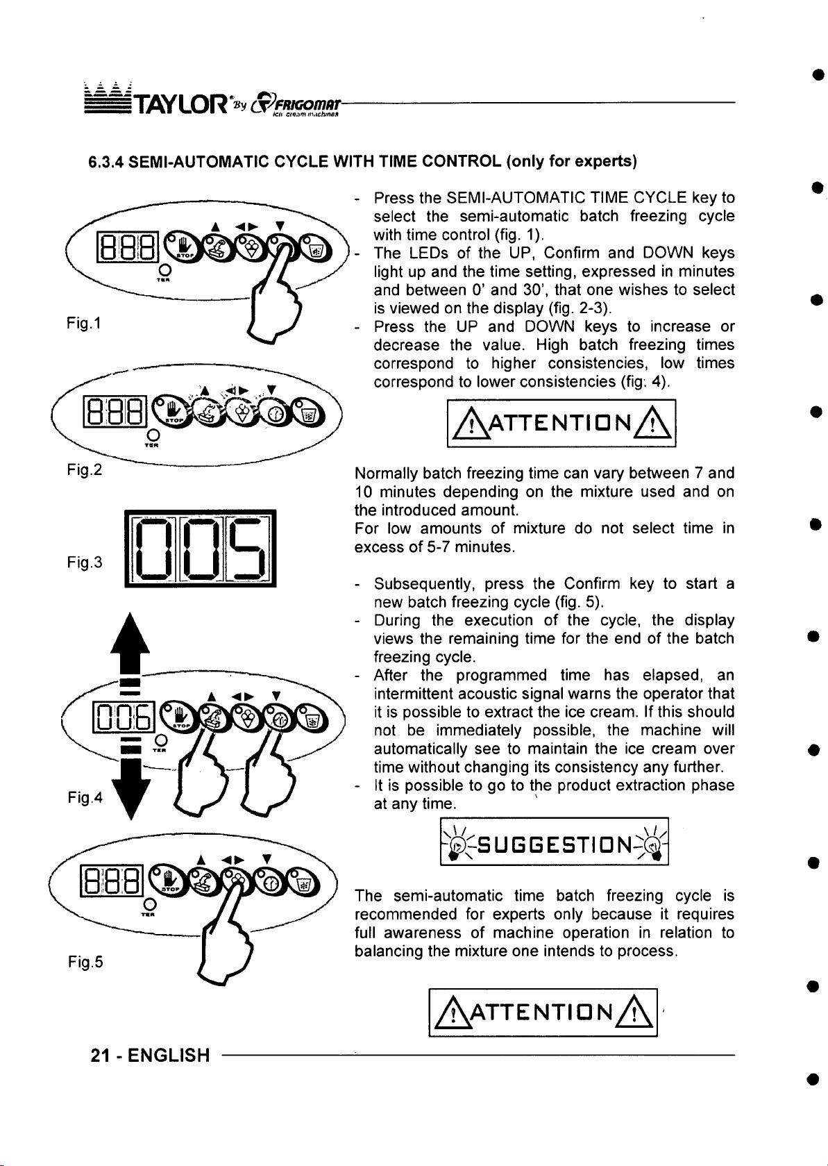
IT flY LO R *® y (jpfR iG om aT
■ ■" • ■ /cft cip:m /n.jc/UftflJi
6.3.4 SEMI-AUTOMATIC CYCLE WITH TIME CONTROL (only for experts)
Press the SEMI-AUTOMATIC TIME CYCLE key to
select the semi-automatic batch freezing cycle
with time control (fig. 1).
The LEDs of the UP, Confirm and DOWN keys
light up and the time setting, expressed in minutes
and between 0’ and 30’, that one wishes to select
is viewed on the display (fig. 2-3).
Press the UP and DOWN keys to increase or
decrease the value. High batch freezing times
correspond to higher consistencies, low times
correspond to lower consistencies (fig. 4).
A a t t e n t id n A
Fig.2
Fig.3
n
u
u
b
Normally batch freezing time can vary between 7 and
10 minutes depending on the mixture used and on
the introduced amount.
For low amounts of mixture do not select time in
excess of 5-7 minutes.
- Subsequently, press the Confirm key to start a
new batch freezing cycle (fig. 5).
- During the execution of the cycle, the display
views the remaining time for the end of the batch
freezing cycle.
- After the programmed time has elapsed, an
intermittent acoustic signal warns the operator that
it is possible to extract the ice cream. If this should
not be immediately possible, the machine will
automatically see to maintain the ice cream over
time without changing its consistency any further.
- It is possible to go to the product extraction phase
at any time.
-j ^ iS U G G E S T m N .i ^ -
21 - ENGLISH
The semi-automatic time batch freezing cycle is
recommended for experts only because it requires
full awareness of machine operation in relation to
balancing the mixture one intends to process.
A a t te n t io n A
Page 61
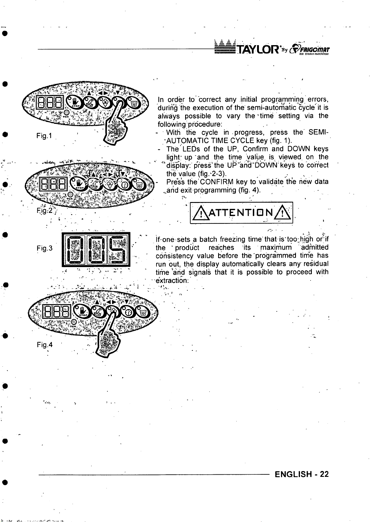
n iW L O R S ^ e m a d m ar
■ ' " " • • " ■ » v ,- * /go cfan ni ftuir.Mnos
In order to correct any initial programming errors,
during the execution of the semi-autornatic cycle'it is
always possible to vary the’time setting via the
following procedure:
- With the cycle in progress, press the SEMI-
; AUTOMATIC TIME CYCLE key (fig. 1).
- The LEDs of the UP, Confirm and DOWN keys
light; up and the time value, is. viewed on the
""‘ display: press’the UP'ahcl^DbwN' keys to correct
the value (fig.’2-3). ^ ,
- Press the CONFIRM key to validate the hew data
..and exit programming (fig. 4).
Fig-2y
Fig.3
ATTENTION/!
* .1
If'One sets a batch freezing time that is*too;high or if
the ‘ product reaches its maxirfium admitted
consistency value before the'programmed time has
run out, the display automatically clears any residual
tirhe and signals that it is possible to proceed with
extraction;
ENGLISH -22
Page 62
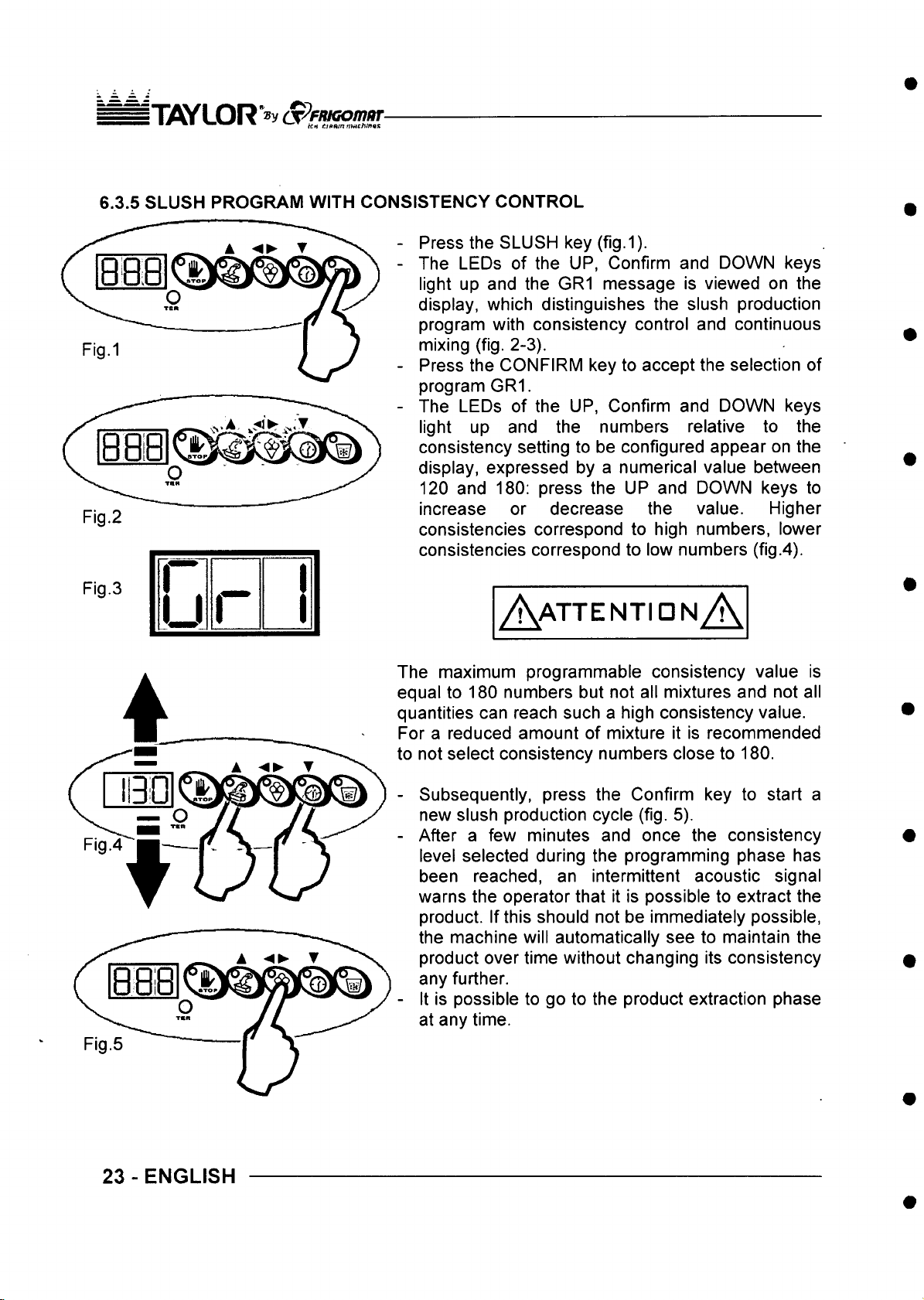
ITflYL OR S ^ fn K om a r
■ * ■ ^ V --T f.,anm tjMChmvs
6.3.5 SLUSH PROGRAM WITH CONSISTENCY CONTROL
Press the SLUSH key (fig. 1).
The LEDs of the UP, Confirm and DOWN keys
light up and the GR1 message is viewed on the
display, which distinguishes the slush production
program with consistency control and continuous
mixing (fig. 2-3).
Press the CONFIRM key to accept the selection of
program GR1.
The LEDs of the UP, Confirm and DOWN keys
light up and the numbers relative to the
consistency setting to be configured appear on the
display, expressed by a numerical value between
120 and 180; press the UP and DOWN keys to
Fig.2
increase or decrease the value. Higher
consistencies correspond to high numbers, lower
consistencies correspond to low numbers (fig.4).
Fig.3
u
A a t t e n tid n A
The maximum programmable consistency value is
equal to 180 numbers but not all mixtures and not all
quantities can reach such a high consistency value.
For a reduced amount of mixture it is recommended
to not select consistency numbers close to 180.
- Subsequently, press the Confirm key to start a
new slush production cycle (fig. 5).
- After a few minutes and once the consistency
level selected during the programming phase has
been reached, an intermittent acoustic signal
warns the operator that it is possible to extract the
product. If this should not be immediately possible,
the machine will automatically see to maintain the
product over time without changing its consistency
any further.
- It is possible to go to the product extraction phase
at any time.
23-ENGLISH
Page 63
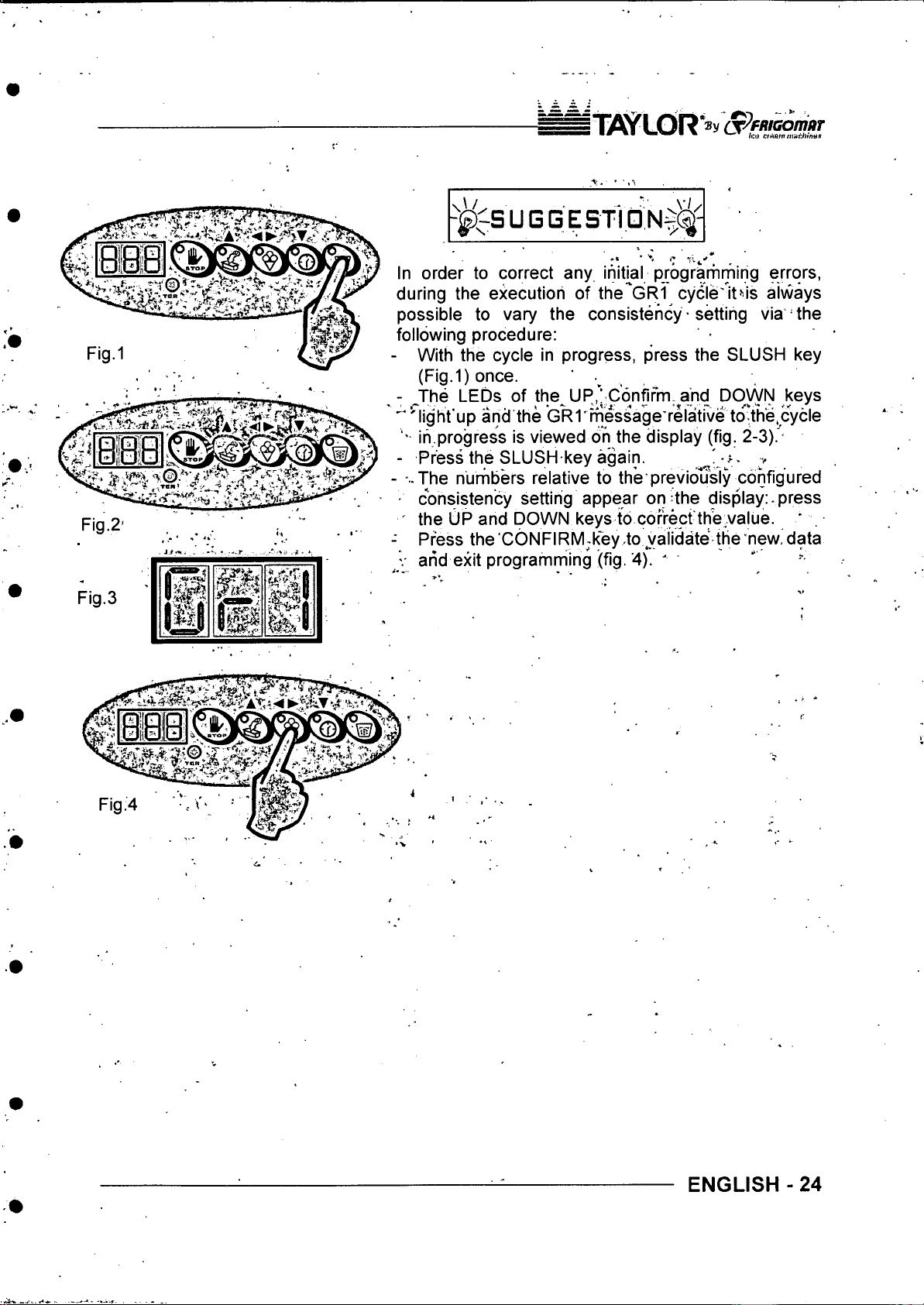
ITW?LOR ®v C p fn iG o m r
^ ^ - S U G G E S f ld N $ i ^
\ 'y
In order to correct any initial progrartiming errors,
during the execution of the'GRI cycle'itMs always
possible to vary the consistency • setting via the
following procedure:
- With the cycle in progress, press the SLUSH key
(Fig.1) once. ,
^The LEDs of the UP,’;C6nfifrTi-^and DOWN keys
^ light'up and the GRI' message relative to th'e.c^^^
' ih progress is viewed oh the display (fig. 2 -3 )!-
- Press the SLUSH key again. - '
- -..The nurribers relative to the previously configured
■ consistency setting appear on the display: press
Fig.2-
Fig.3
Press the'GONFIRM;key to validate the new, data
arid exit programming (fig. 4). '
ENGLISH - 24
Page 64
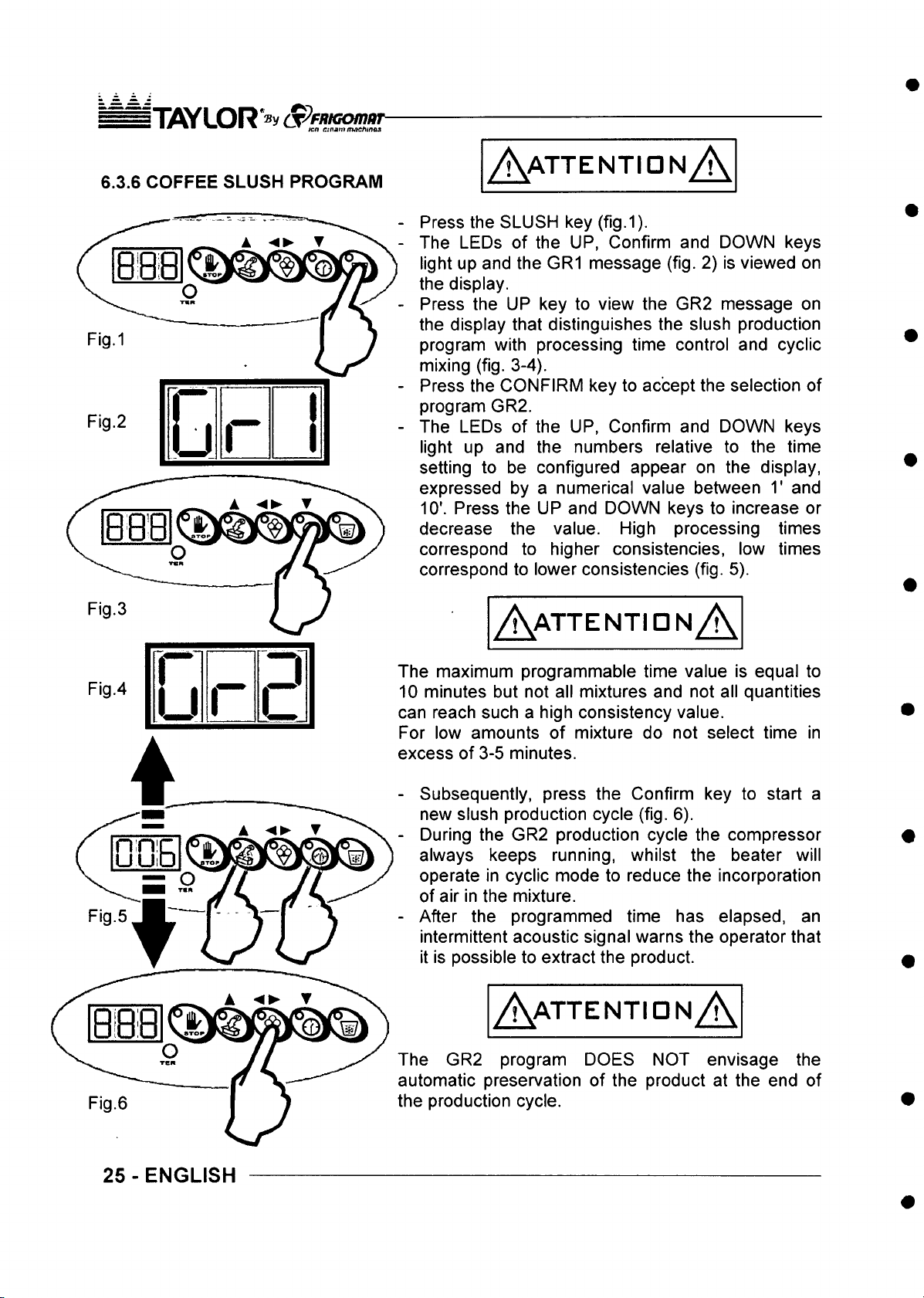
T flY L O R *® y S^fR iG o m ar
’ tea etf^a m n uiC hin^
6.3.6 COFFEE SLUSH PROGRAM
O
▼VR
Fig.3
A aTTENTIDN A
- Press the SLUSH key (fig.1).
- The LEDs of the UP, Confirm and DOWN keys
light up and the GR1 message (fig. 2) is viewed on
the display.
- Press the UP key to view the GR2 message on
the display that distinguishes the slush production
program with processing time control and cyclic
mixing (fig. 3-4).
- Press the CONFIRM key to accept the selection of
program GR2.
- The LEDs of the UP, Confirm and DOWN keys
light up and the numbers relative to the time
setting to be configured appear on the display,
expressed by a numerical value between T and
10'. Press the UP and DOWN keys to increase or
decrease the value. High processing times
correspond to higher consistencies, low times
correspond to lower consistencies (fig. 5).
A a t t e n t id n A
Fig.4
n
u
r
PI
L
The maximum programmable time value is equal to
10 minutes but not all mixtures and not all quantities
can reach such a high consistency value.
For low amounts of mixture do not select time in
excess of 3-5 minutes.
- Subsequently, press the Confirm key to start a
new slush production cycle (fig. 6).
- During the GR2 production cycle the compressor
always keeps running, whilst the beater will
operate in cyclic mode to reduce the incorporation
of air in the mixture.
- After the programmed time has elapsed, an
intermittent acoustic signal warns the operator that
it is possible to extract the product.
A a t t e n t id n A
The GR2 program DOES NOT envisage the
automatic preservation of the product at the end of
the production cycle.
25 - ENGLISH
Page 65
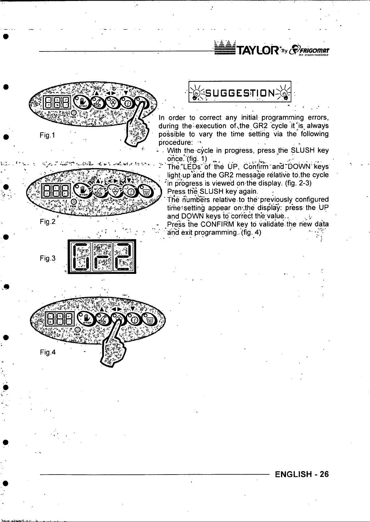
n ys yL O R '» y S^P niG omur
" ▼ k f t Cfdom nm ch iiu ui
Fig.2
Fig.3
TRWrw-
IlS i
- ^l SU G G E STI DN - 5( ^ ^
, , r- « r- r.-r. r-i ... vU /
In order to correct any initial programming errors,
during the-execution of..the GR2 cycle it*’is always
possible to vary the time setting via the following
procedure: ^
■ With the cycle in progress, press Jthe SLUSH key
fc.
once?'(fig. 1) '
The 'LEDs’ of the UP, Confirm an^'DOWN'keys
.........
light up*'and the GR2 message relative to.the cycle
'"in progress is viewed on the display, (fig. 2-3)
Press the SLUSH key again.
‘ th*e numbers relative to the’previously configured
time'setting appear om.the display: press the UP
and DOWN keys to correct the vajue.. .
- ^Press the CONFIRM key to validate the new data
■ ari^ exit programming..’(fig. 4) ' * '.O
-
ENGLISH - 26
Page 66
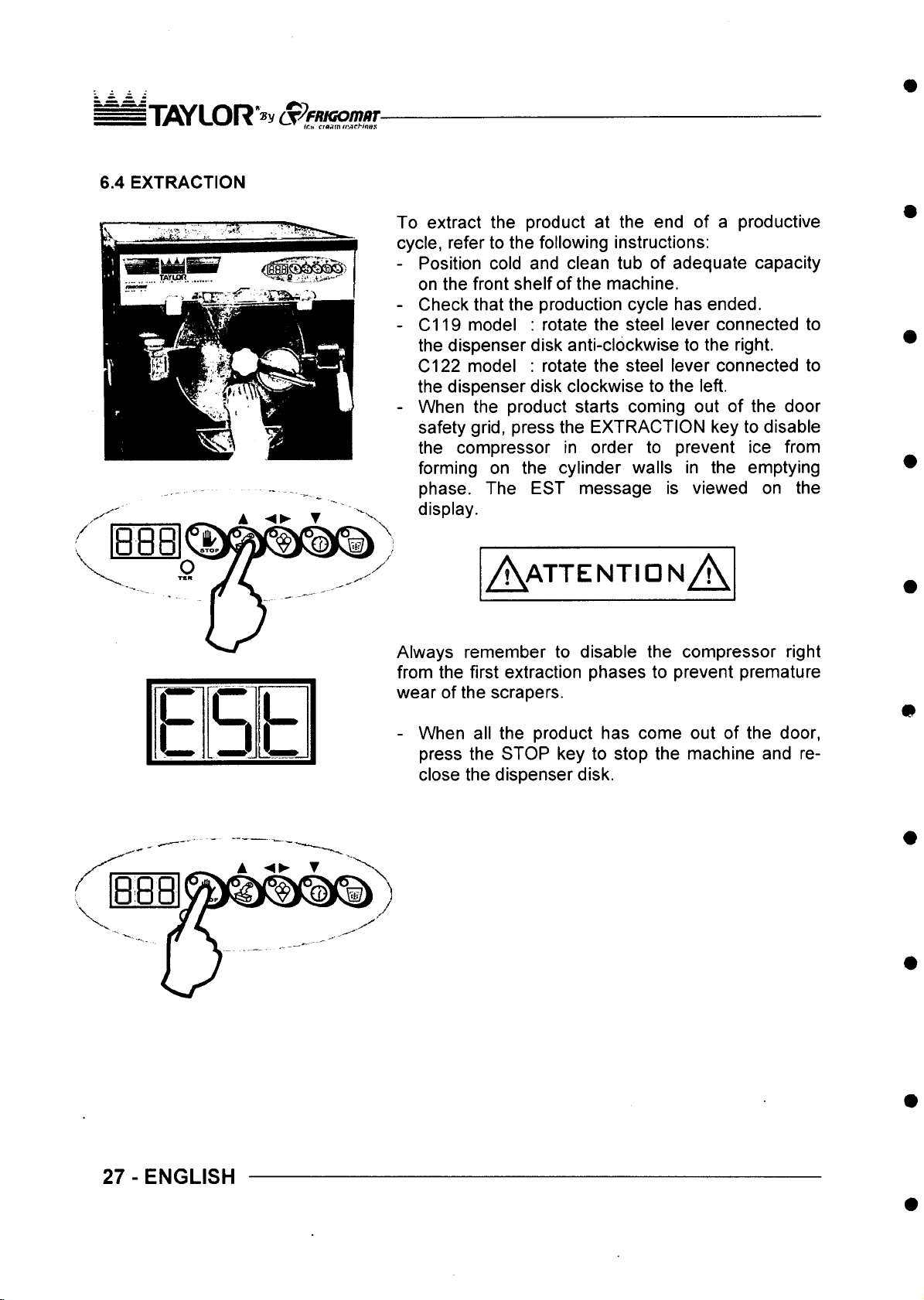
il]flY L O R *» y (T ^fHiG om/ir
• ^ ^ cfpam«!flrHnss
6.4 EXTRACTION
To extract the product at the end of a productive
cycle, refer to the following instructions:
- Position cold and clean tub of adequate capacity
on the front shelf of the machine.
- Check that the production cycle has ended.
- C119 model : rotate the steel lever connected to
the dispenser disk anti-clockwise to the right.
model : rotate the steel lever connected to
C l 22
the dispenser disk clockwise to the left.
- When the product starts coming out of the door
safety grid, press the EXTRACTION key to disable
the compressor in order to prevent ice from
forming on the cylinder walls in the emptying
phase. The EST message is viewed on the
display.
c
c
u □ J
L J
A a t t e n t io n A
Always remember to disable the compressor right
from the first extraction phases to prevent premature
wear of the scrapers.
- When all the product has come out of the door,
press the STOP key to stop the machine and re
close the dispenser disk.
27 - ENGLISH
Page 67
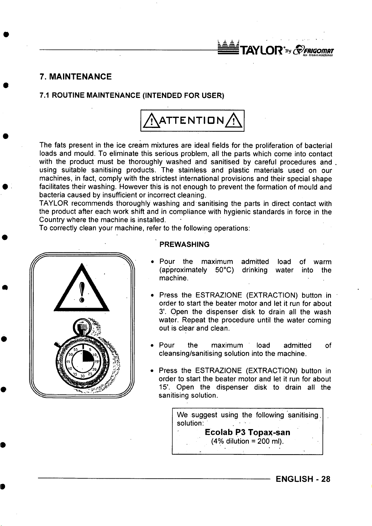
IT iflY L O R ®y a P ftiiG o m iiT
* ■ .m W T ien nffsattunne hinaf!
7. MAINTENANCE
7.1 ROUTINE MAINTENANCE (INTENDED FOR USER)
A a t t e n t id n A .
The fats present in the ice cream mixtures are ideal fields for the proliferation of bacterial
loads and mould. To eliminate this serious problem, all the parts which come into contact
with the product must be thoroughly washed and sanitised by careful procedures and
using suitable sanitising products. The stainless and plastic materials used on our
machines, in fact, comply with the strictest international provisions and their special shape
facilitates their washing. However this is not enough to prevent the formation of mould and
bacteria caused by insufficient or incorrect cleaning.
TAYLOR recommends thoroughly washing and sanitising the parts in direct contact with
the product after each work shift and in compliance with hygienic standards in force in the
Country where the machine is installed.
To correctly clean your machine, refer to the following operations:
PREWASHING
• Pour the maximum admitted load of warm
(approximately 50°C) drinking water into the
machine.
• Press the ESTRAZIONE (EXTRACTION) button in
order to start the beater motor and let it run for about
3'. Open the dispenser disk to drain all the wash
water. Repeat the procedure until the water coming
out is clear and clean.
Pour the maximum load admitted
cleansing/sanitising solution into the machine.
Press the ESTRAZIONE (EXTRACTION) button in
order to start the beater motor and let it run for about
15'. Open the dispenser disk to drain all the
sanitising solution.
We suggest using the following sanitising.
solution:
of
Ecolab P3 Topax-san
(4% dilution = 200 ml).
ENGLISH -28
Page 68
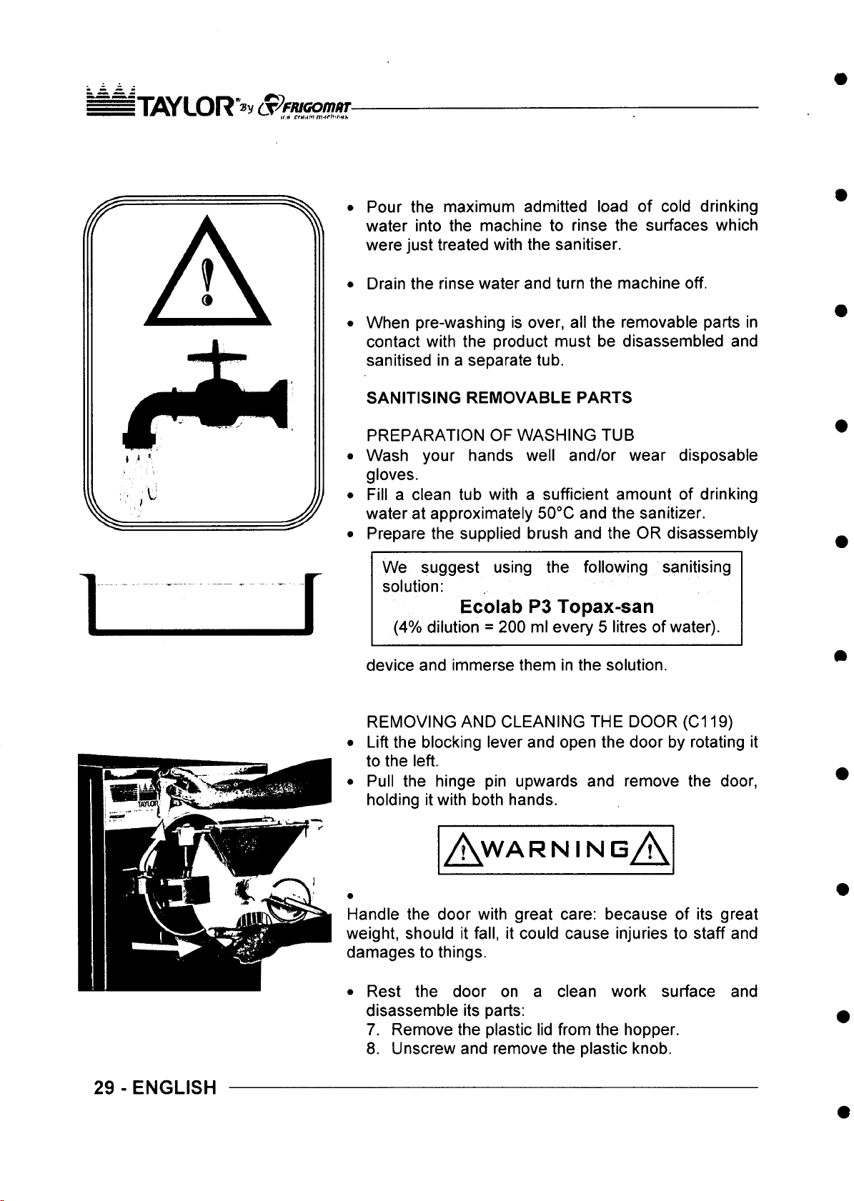
ITOYLOR a p fiu G o m iiT
Pour the maximum admitted load of cold drinking
water into the machine to rinse the surfaces which
were just treated with the sanitiser.
Drain the rinse water and turn the machine off.
When pre-washing is over, all the removable parts in
contact with the product must be disassembled and
sanitised in a separate tub.
SANITISING REMOVABLE PARTS
PREPARATION OF WASHING TUB
Wash your hands well and/or wear disposable
gloves.
Fill a clean tub with a sufficient amount of drinking
water at approximately 50°C and the sanitizer.
Prepare the supplied brush and the OR disassembly
1
f
We suggest using the following sanitising
solution:
Ecolab P3 Topax-san
(4% dilution = 200 ml every 5 litres of water).
device and immerse them in the solution.
REMOVING AND CLEANING THE DOOR (C119)
Lift the blocking lever and open the door by rotating it
to the left.
Pull the hinge pin upwards and remove the door,
holding it with both hands.
A.w a r n i n e A
Handle the door with great care: because of its great
weight, should it fall, it could cause injuries to staff and
damages to things.
29 - ENGLISH
• Rest the door on a clean work surface and
disassemble its parts:
7. Remove the plastic lid from the hopper.
8. Unscrew and remove the plastic knob.
Page 69
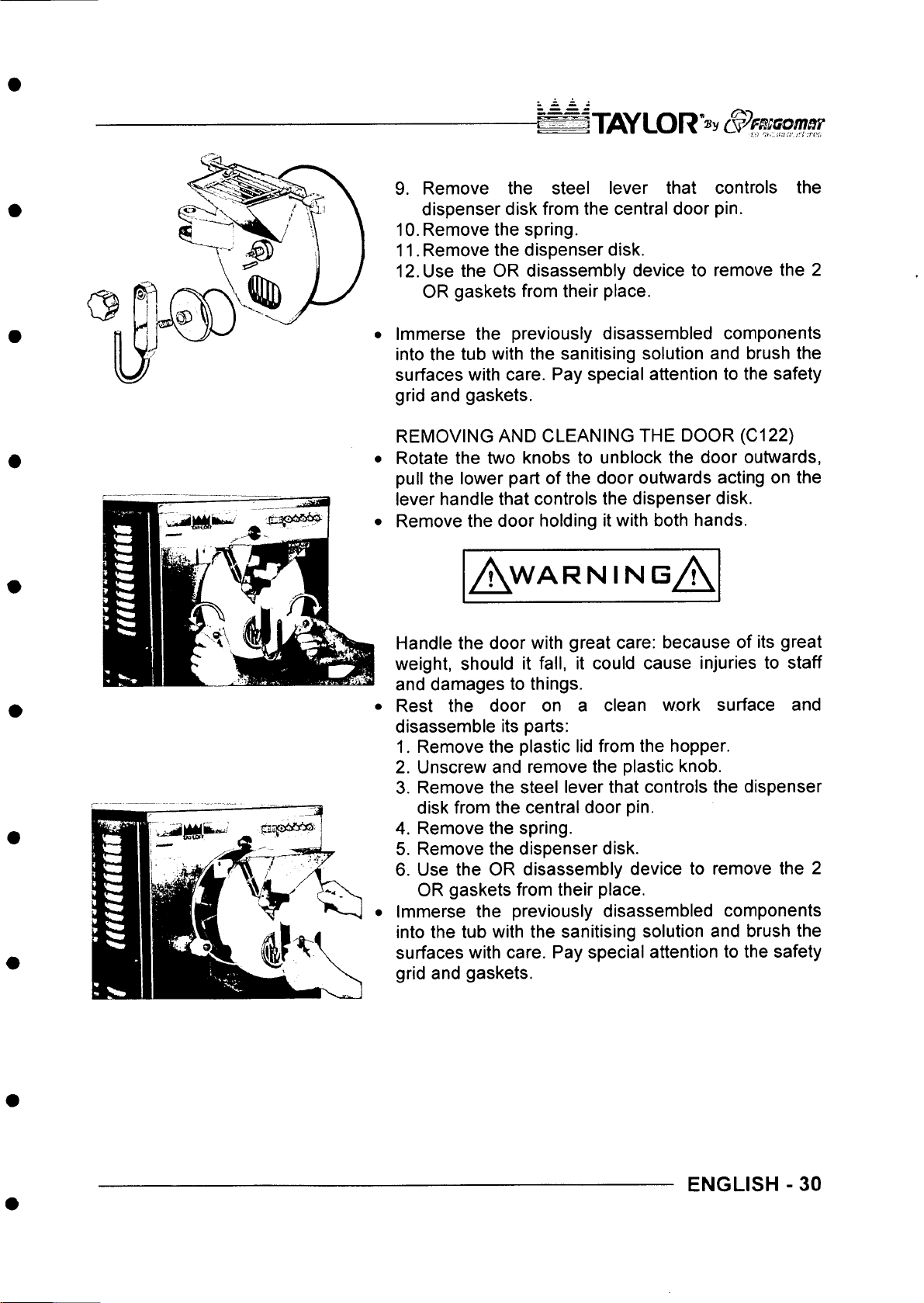
iTA/LOR
9. Remove the steel lever that controls the
dispenser disk from the central door pin.
10. Remove the spring.
11. Remove the dispenser disk.
12. Use the OR disassembly device to remove the 2
OR gaskets from their place.
Immerse the previously disassembled components
into the tub with the sanitising solution and brush the
surfaces with care. Pay special attention to the safety
grid and gaskets.
REMOVING AND CLEANING THE DOOR (C122)
Rotate the two knobs to unblock the door outwards,
pull the lower part of the door outwards acting on the
lever handle that controls the dispenser disk.
Remove the door holding it with both hands.
A w a r n in g A
Handle the door with great care: because of its great
weight, should it fall, it could cause injuries to staff
and damages to things.
Rest the door on a clean work surface and
disassemble its parts:
1. Remove the plastic lid from the hopper.
2. Unscrew and remove the plastic knob.
3. Remove the steel lever that controls the dispenser
disk from the central door pin.
4. Remove the spring.
5. Remove the dispenser disk.
6. Use the OR disassembly device to remove the 2
OR gaskets from their place.
Immerse the previously disassembled components
into the tub with the sanitising solution and brush the
surfaces with care. Pay special attention to the safety
grid and gaskets.
ENGLISH -30
Page 70
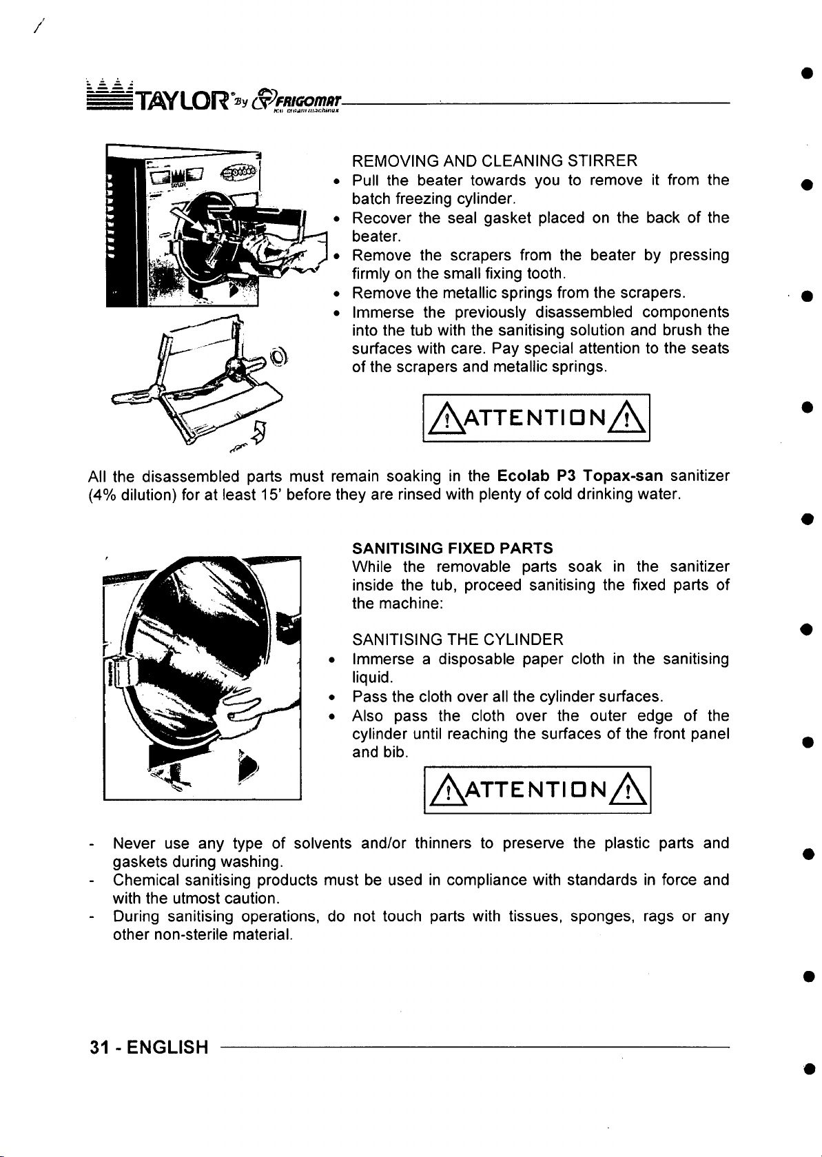
/
IT iO y L O R ^ ^ fR IG O m U T
■ ■ * icAt cu ^aitt iM Ch in Q s
REMOVING AND CLEANING STIRRER
Pull the beater towards you to remove it from the
batch freezing cylinder.
Recover the seal gasket placed on the back of the
beater.
Remove the scrapers from the beater by pressing
firmly on the small fixing tooth.
Remove the metallic springs from the scrapers.
Immerse the previously disassembled components
into the tub with the sanitising solution and brush the
surfaces with care. Pay special attention to the seats
of the scrapers and metallic springs.
A a t t e n t id n A
All the disassembled parts must remain soaking in the Ecolab P3 Topax-san sanitizer
(4% dilution) for at least 15’ before they are rinsed with plenty of cold drinking water.
SANITISING FIXED PARTS
While the removable parts soak in the sanitizer
inside the tub, proceed sanitising the fixed parts of
the machine:
SANITISING THE CYLINDER
Immerse a disposable paper cloth in the sanitising
liquid.
Pass the cloth over all the cylinder surfaces.
Also pass the cloth over the outer edge of the
cylinder until reaching the surfaces of the front panel
and bib.
A a t t e n t id n A
Never use any type of solvents and/or thinners to preserve the plastic parts and
gaskets during washing.
Chemical sanitising products must be used in compliance with standards in force and
with the utmost caution.
During sanitising operations, do not touch parts with tissues, sponges, rags or any
other non-sterile material.
31 - ENGLISH
Page 71
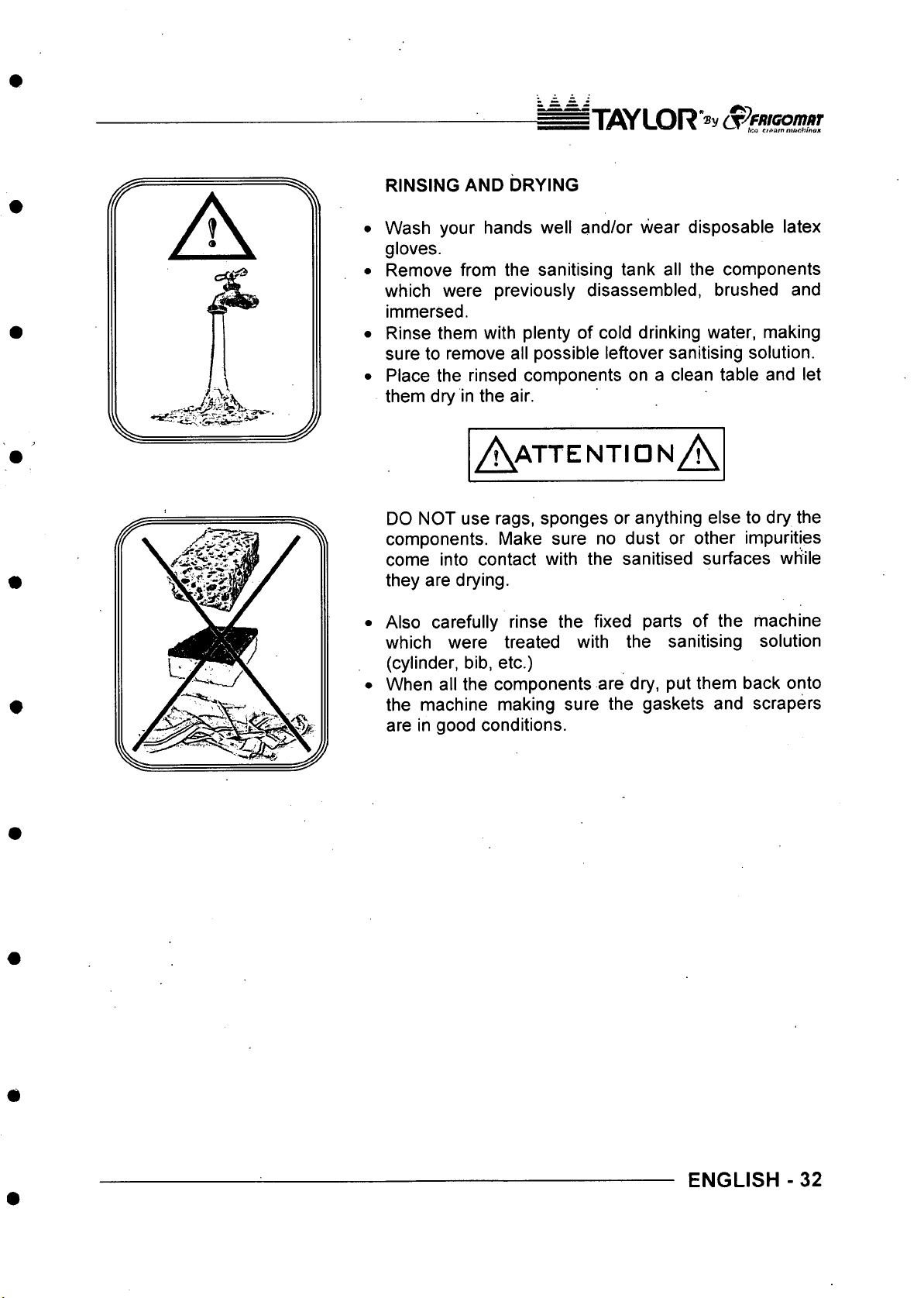
o P f R iG o itu iT
RINSING AND DRYING
Wash your hands well and/or wear disposable latex
gloves.
Remove from the sanitising tank all the components
which were previously disassembled, brushed and
immersed.
Rinse them with plenty of cold drinking water, making
sure to remove all possible leftover sanitising solution.
Place the rinsed components on a clean table and let
them dry in the air.
/K a t t e n t io n A
DO NOT use rags, sponges or anything else to dry the
components. Make sure no dust or other impurities
come into contact with the sanitised surfaces while
they are drying.
Also carefully rinse the fixed parts of the machine
which were treated with the sanitising solution
(cylinder, bib, etc.)
When all the components are dry, put them back onto
the machine making sure the gaskets and scrapers
are in good conditions.
ENGLISH -32
Page 72
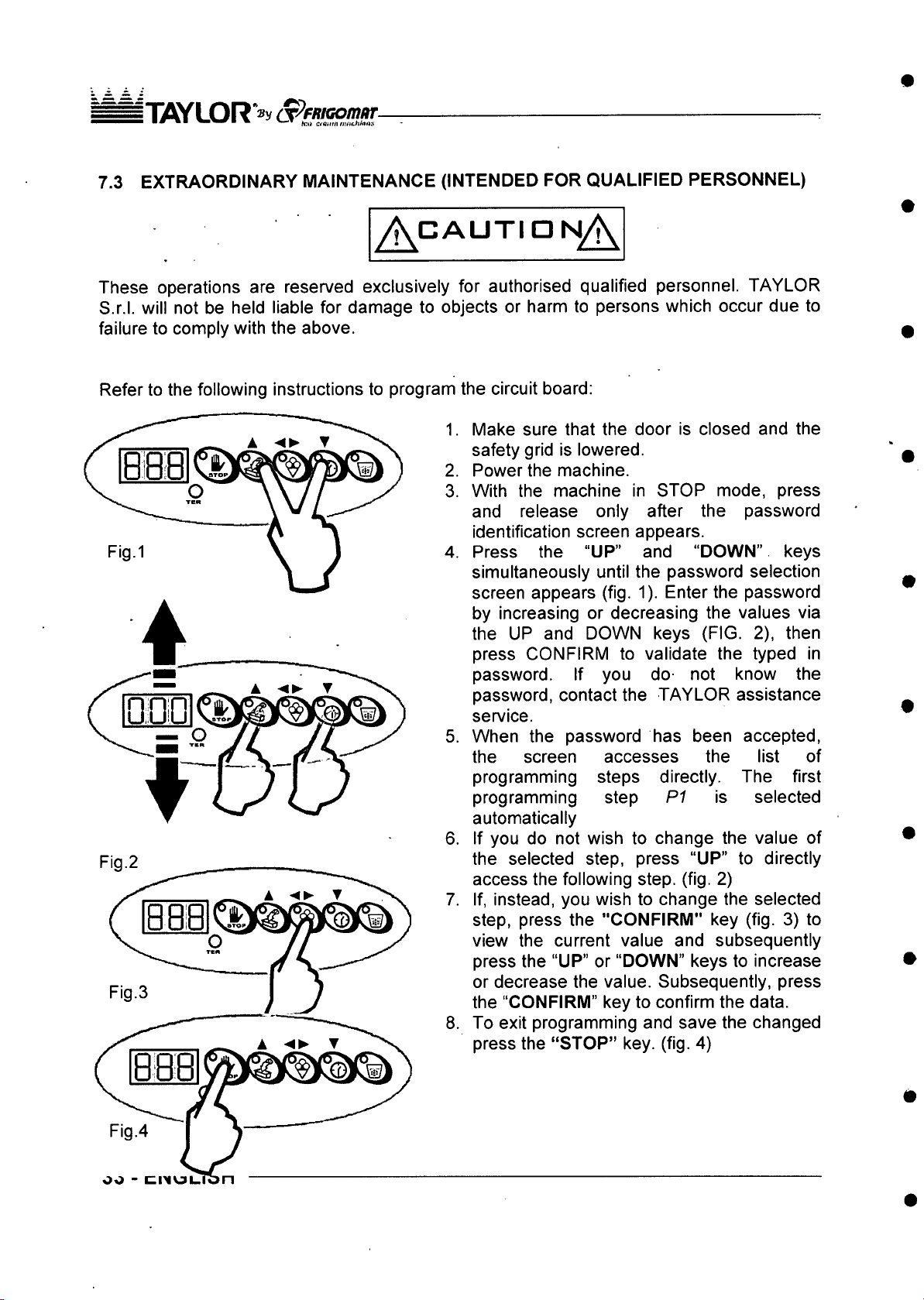
i T7iYLOR"®y S^fRKonutr
■ mm ■ m - w * ctamn nu ichlnns
7.3 EXTRAORDINARY MAINTENANCE (INTENDED FOR QUALIFIED PERSONNEL)
/^ C A U T ID N /\
These operations are reserved exclusively for authorised qualified personnel. TAYLOR
S.r.l. will not be held liable for damage to objects or harm to persons which occur due to
failure to comply with the above.
Refer to the following instructions to program the circuit board:
Make sure that the door is closed and the
1.
safety grid is lowered.
Power the machine.
2.
With the machine in STOP mode, press
3.
and release only after the password
identification screen appears.
Press the “UP” and “DOWN” keys
4.
simultaneously until the password selection
screen appears (fig. 1). Enter the password
by increasing or decreasing the values via
the UP and DOWN keys (FIG. 2), then
press CONFIRM to validate the typed in
password. If you do not know the
password, contact the TAYLOR assistance
service.
When the password has been accepted,
5.
the screen accesses the list of
programming steps directly. The first
P 1 is selected
Fig.2
programming step
automatically
If you do not wish to change the value of
6.
the selected step, press “UP” to directly
access the following step. (fig. 2)
If, instead, you wish to change the selected
7.
step, press the "CONFIRM" key (fig. 3) to
view the current value and subsequently
press the “UP” or “DOWN” keys to increase
or decrease the value. Subsequently, press
the “CONFIRM” key to confirm the data.
To exit programming and save the changed
8.
press the “STOP” key. (fig. 4)
OO - CI^IOL.
Page 73
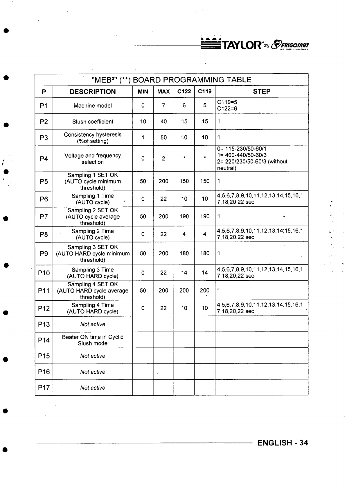
IT O Y L O R ^ y (S ^ F R K io m a r
"MEB^" (**) BOARD PR OGRAM M ING TABLE
P
P1
P2
P3
P4
P5
P6
P7
P8
P9
P10
P11
P12
DESCRIPTION
Machine model 0
Slush coefficient
Consistency hysteresis
(%of setting)
Voltage and frequency
selection
Sampling 1 SET OK
(AUTO cycle minimum
threshold)
Sampling 1 Time
(AUTO cycle)
Sampling 2 SET OK
(AUTO cycle average
threshold)
Sampling 2 Time
(AUTO cycle)
Sampling 3 SET OK
(AUTO HARD cycle minimum
threshold)
Sampling 3 Time
(AUTO HARD cycle)
Sampling 4 SET OK
(AUTO HARD cycle average
threshold)
Sampling 4 Time
(AUTO HARD cycle)
MIN
50
MAX
10 40
1
0 2
50
0 22 10
50 200 190
0
50 200 180
0
0
200 150 150
200 200 200
C122 C119
7 6
50
22 4
22 14 14
22 10 10
15 15
10 10
*
10
190 1
180
STEP
C119=5
5
C l22=6
1
1
0= 115-230/50-60/1
1=400-440/50-60/3
*
2= 220/230/50-60/3 (without
neutral)
1
4,5,6,7,8,9,10,11,12,13,14,15,16,1
7,18,20,22 sec.
4,5,6,7,8,9,10,11,12,13,14;15,16,1
4
7,18,20,22 sec.
1
4.5,6,7,8,9,10,11,12,13,14,15,16,1
7,18,20,22 sec.
1
4,5,6,7,8,9,10,11,12,13,14,15,16,1
7,18,20,22 sec.
P13
P14
P15
P16
P17
Not active
Beater ON time in Cyclic
Slush mode
Not active
Not active
Not active
ENGLISH - 34
Page 74
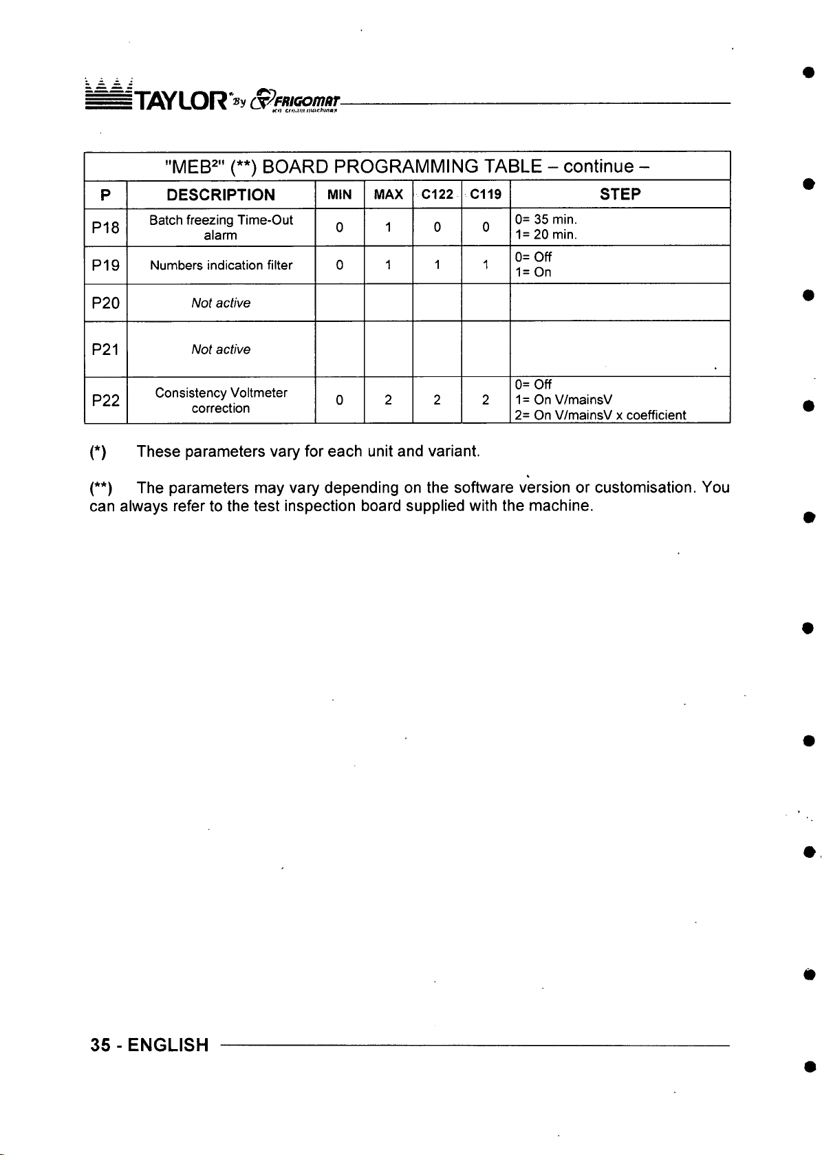
IT flY L O R *» y (^ F M & D tn o T
"MEB^" (**) BOARD PROGRA MMING TABLE - continue -
P
P18
P19
P20
P21
P22
DESCRIPTION
Batch freezing Time-Out
alarm
Numbers indication filter 0
MIN MAX
Not active
Not active
Consistency Voltmeter
correction
0
0
C122
1 0 0
1
2 2 2
C119
1 1
STEP
0= 35 min.
1= 20 min.
0= Off
1= On
0= Off
1 = On V/mainsV
2= On V/mainsV x coefficient
(*) These parameters vary for each unit and variant.
(**) The parameters may vary depending on the software version or customisation. You
can always refer to the test inspection board supplied with the machine.
35 - ENGLISH
Page 75
^ ? F R ia o m R T
macchine per gelato
WEEE
INFORMAZIONE AGLI UTENTI
^ T L I V " ^ UNI EN IS O 9 0 0 1 :2000
_ _ _ N u m e r o C ert ifi c a to
, 5 U U 50 i 00 565 0
A z ien d a C er tif lca ta
Ai sensi dell’art. 13 del Decreto Legislative 25 Luglio 2005, n. 151 “Attuazione delle Direttive 2002/95/CE,
2002/96/CE e 2003/108/CE, relative alia riduzione dell’uso di sostanze pericolose nelle apparecchiature
elettriche ed elettroniche, nonche alio smaltimento dei rifiuti”
II simbolo del cassonetto barrato riportato sull’apparecchiatura o sulla confezione indica che il prodotto deve
essere raccolto separatamente dagli altri rifiuti.
La raccolta differenziata della presente apparecchiatura giunta a fine vita 6 organizzata e gestita dal produttore.
L’utente che vorr^ disfarsi della presente apparecchiatura dovr^ quindi contattare il produttore e seguire il
sistema che questo ha adottato per consentire la raccolta separata dell’apparecchiatura giunta a fine vita.
L'adeguata raccolta differenziata per I’avvio successive dell'apparecchiatura dimessa al riciclaggio, al
trattamento e alio smaltimento ambientalmente compatibile contribuisce ad evitare possibili effetti negativi
suN’ambiente e sulla salute e favorisce il reimpiego e/o ricicio dei materiali di cui 6 composta I’apparecchiatura.
Lo smaltimento abusivo del prodotto da parte del detentore comporta I’applicazione delle sanzioni
amministrative previste dalla normativa vigente
USER’S NOTICE
As per the “ European directives 2002/95/EC, 2002/96/EC and 2003/108/EC, on the restriction of the use
of certain hazardous substances in electric and electronic equipment and disposal of waste”.
The above symbol indicated on the equipment or the packaging, means that the relevant products waste at the
end of its life must be disposed in separate way.
The disposal of this equipment at the end of its life is handled by the producer. The user who wants to dispose
of this equipment must contact the producer and comply with the system adopted by the producer to properly
dispose of the equipment.
The proper dismantling of the equipment, its recycling, treatment and environmentally-friendly disposal
contribute to the protection of the environment and human health and encourage the re-utilization and/or
recycling of the materials used in the equipment.
The incorrect disposal of the product by the user may lead to the application of the levy of fines as
appiicabie to the iocai legisiation.
Page 76
^ F R i a o m n T
macchinepergelato
Nach „Aktualisierung der Vorschrift 2002/95/EG, 2002/96/EG und 2003/108/EG, beziiglich der
Anwendungsverminderung von gefahrlichen Substanzen in elektrischen und elektronischen
Geraten/Maschinen, als auch fur die Abfallentsorgung
Das Symbol der durchgestrichenen Abfalltonne auf Geraten/Maschinen Oder auf Ihrer Verpackung zeigt an,
dass das Produkt bei Gebrauchsende separat von den anderen Abfallen entsorgt warden muss.
Die getrennte Abfallentsorgung des vorliegenden Gerates/Maschine, welches seine eigene Gebrauchsdauer
erreicht hat wird vom Hersteller organisiert. Der Bediener/Benutzer der das Gerat/Maschine entsorgen muss,
muss sich somit mit dem Hersteller in Verbindung setzen und den von diesem angenommenen
Entsorgungsablauf zur getrennten Abfallentsorgung des an das Gebrauchsende angelangte Gerat/Maschine
Die entsprechend durchgefuhrte Abfallentsorgung zum folgenden Recycling der entsorgten
Gerate/Maschinen, als auch die Verarbeitung und fachgerechte Umweltentsorgung tragt dazu bei, negative
Umwelt- und Gesundheitseinflusse zu produzieren und fOrdert die Wiederverwertung u/o Recycling der
Materialien, aus denen sich das Gerat/Maschine zusammensetzt.
Die missbrauchliche Entsorgung von Produkten von Seiten des Halters fiihrt zur Auferiegung von
Verwaitungssanktionen, die von den giiltigen Normen vorgeschrieben werden.
BEDIENER-/BENUTZERHINWEIS
befolgen.
r- n"i v/i
A z ien d a C or tific a ta
UN I EN 180 9 0 0 1 :2000
N u me ro C e rtif ica to
50 1 00 5 6 50
INFORMATIONS A LA CLIENTELE
Aux termes de“Application des Directives 2002/95/CE, 2002/96/CE et 2003/108/CE, concernant ia
diminution de I’utiiisation des matieres dangereuses dans les appareiis eiectriques et electroniques,
ainsi que i’eiimination des dechets”
Le symbols de la poubelle barr6e appliqua sur I’appareil ou sur I’emballage, indique que le produit en fin de
vie utile doit §tre aiimin6 separament des autres dachets.
Le ramassage diffarencia de I'appareil en fin de vie est organisa et gara par le producteur. Par consaquent,
I’usager qui souhaitera aiiminer son matariel devra contactor le producteur et suivre la procadure que ce
dernier aura adoptae pour permettre le ramassage diffarencia des aquipements en fin de vie.
Un ramassage diffarencia appropria pour I’envoi des aquipements aiiminas vers le recyclage, le traitement et
raiimination compatible avec le respect de I’environnement, contribue a aviter tout aventuel impact nagatif
sur I’environnement et sur la santa et favorise la rautilisation et le recyclage des matahaux composant les
appareiis aiiminas.
Toute elimination abusive du produit de la part de I’usager comporte I’application des sanctions
administratives prevues par la reglementation en vigueur.
INFORMACION A LOS USUARIOS
de acuerdo con la “ApUcacion de las Directivas 2002/95/CE, 2002/96/CE y 2003/108/CE, relativas a la
reduccidn del uso de sustancias peligrosas en los aparatos electricos y electronicos, as! como la
eliminacidn de los residuos"
El simbolo del contenedor tachado presente en el aparato o en la caja indica que el producto al final de su
propia Vida util ha de ser recogido separadamente de los otros residuos.
La recogida selectiva del presente aparato al final de su vida es organizada y gestionada por el productor.
For lo tanto, el usuario que quiera deshacerse del presente aparato tendr^ que contactar con el productor y
seguir el sistema que 6ste ha adoptado para consentir la recogida separada del aparato que ha llegado al
final de su vida.
La adecuada recogida selectiva del aparato, que se ha dejado de usar, para el sucesivo envio a la fase de
reciclaje, al tratamiento y a la eliminacibn ambientalmente compatible contribuye a evitar posibles efectos
negatives sobre el ambiente y la salud y favorece la reutilizacibn y/o reciclaje de los materiales de la que
estb formado el aparato.
La eiiminacibn abusiva del producto por parte del propietario conlleva la aplicacibn de las sanciones
administrativas previstas por la normativa vigente.
Page 77
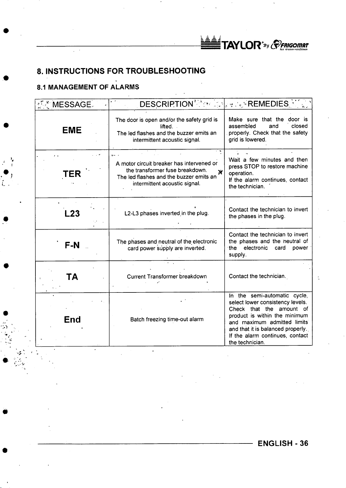
8. INSTRUCTIONS FOR TROUBLESHOOTING
8.1 MANAGEMENT OF ALARMS
IT iflY l O R'® y (jp f R iG o m m
• ^ fco ertffl/71 mi7chin««
’. - t m e s s a g e : -
E ME
TER
L 23
F -N
DESCRIPTION*
The door is open and/or the safety grid is
lifted.
The led flashes and the buzzer emits an
intermittent acoustic signal.
A motor circuit breaker has intervened or
the transformer fuse breakdown. ^
The led flashes and the buzzer emits an
intermittent acoustic signal.
L2-L3 phases inverted, in the plug.
The phases and neutral of the electronic
card power supply are inverted.
. - . ' . '“R EM EDIES ,' V :'
Make sure that the door is
assembled and closed
, properly. Check that the safety
grid is lowered.
Wait a few minutes and then
press STOP to restore machine
operation.
If the alarm continues, contact
the technician.
Contact the technician to invert
the phases in the plug.
Contact the technician to invert
the phases and the neutral of
the electronic card power
supply.
■'r *
T A
En d
Current Transformer breakdown
Batch freezing time-out alarm
Contact the technician.
In the semi-automatic cycle,
select lower consistency levels.
Check that the amount of
product is within the minimum
and maximum admitted limits
and that it is balanced properly..
If the alarm continues, contact
the technician.
ENGLISH -36
Page 78
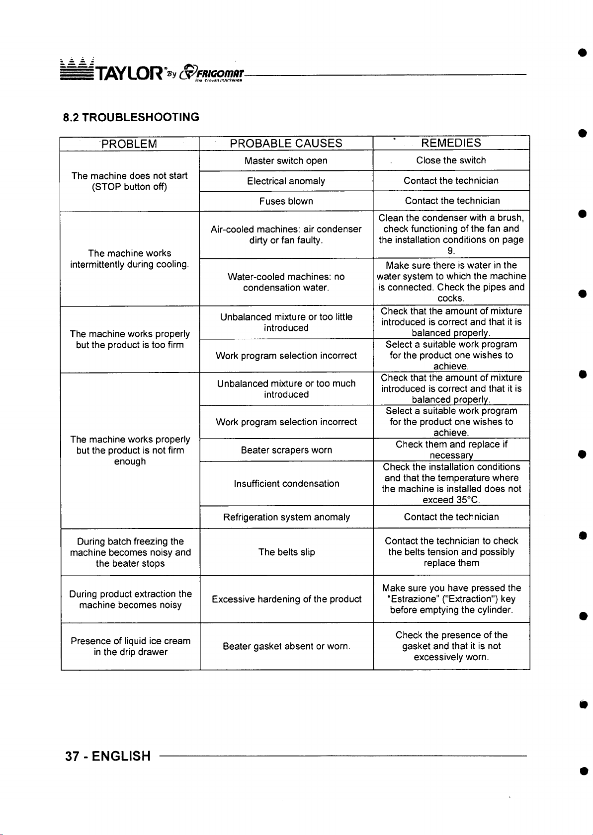
n i W L O R a P f/U G o m m
8.2 TROUBLESHOOTING
PROBLEM
The machine does not start
(STOP button off)
The machine works
intermittently during cooling.
The machine works properly
but the product is too firm
The machine works properly
but the product is not firm
enough
PROBABLE CAUSES
Master switch open
Electrical anomaly
Fuses blown
Air-cooled machines: air condenser
dirty or fan faulty.
Water-cooled machines: no
condensation water.
Unbalanced mixture or too little
introduced
Work program selection incorrect
Unbalanced mixture or too much
introduced
Work program selection incorrect
Beater scrapers worn
Insufficient condensation
REMEDIES
Close the switch
Contact the technician
Contact the technician
Clean the condenser with a brush,
check functioning of the fan and
the installation conditions on page
9.
Make sure there is water in the
water system to which the machine
is connected. Check the pipes and
cocks.
Check that the amount of mixture
introduced is correct and that it is
balanced properly.
Select a suitable work program
for the product one wishes to
achieve.
Check that the amount of mixture
introduced is correct and that it is
balanced properly.
Select a suitable work program
for the product one wishes to
achieve.
Check them and replace if
necessary
Check the installation conditions
and that the temperature where
the machine is installed does not
exceed 35°C.
During batch freezing the
machine becomes noisy and
the beater stops
During product extraction the
machine becomes noisy
Presence of liquid ice cream
in the drip drawer
37 - ENGLISH
Refrigeration system anomaly
The belts slip
Excessive hardening of the product
Beater gasket absent or worn.
Contact the technician
Contact the technician to check
the belts tension and possibly
replace them
Make sure you have pressed the
“Estrazione” ("Extraction") key
before emptying the cylinder.
Check the presence of the
gasket and that it is not
excessively worn.
Page 79
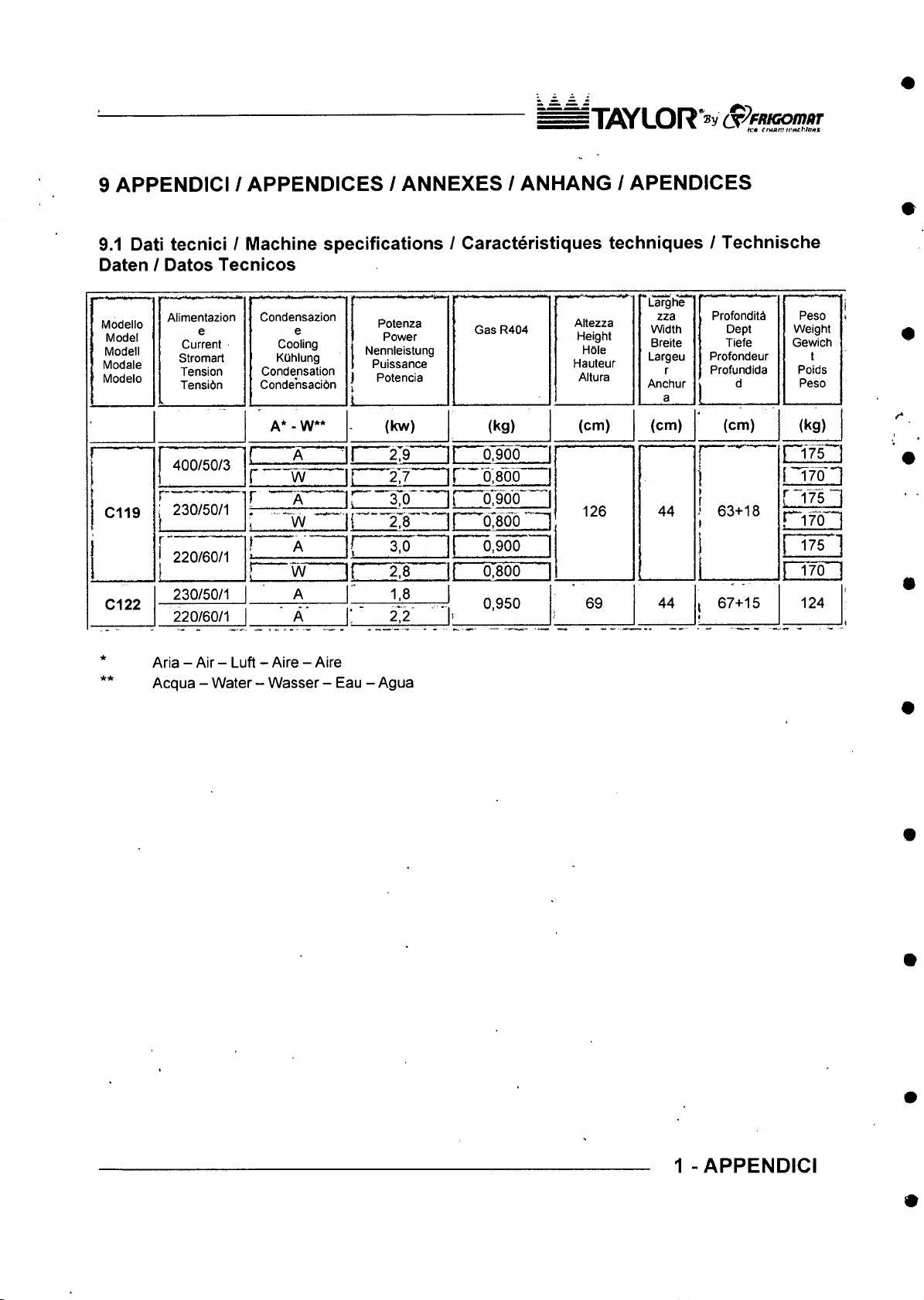
iX flY L O R »y S p F R K io m fiT
9 APPENDICI / APPENDICES / ANNEXES / ANHANG / APENDICES
9.1 Dati tecnici / Machine specifications / Caracteristiques techniques / Technische
Daten / Datos Tecnicos
Modello
Model
Modell
Modale
Modelo
C119
C122
Alimentazion
e
Current
Stromart
Tension
Tensidn
j 400/50/3
j 230/50/1
j 220/60/1
230/50/1
220/60/1
Condensazion
e
Cooling
KQhlung
Condensation
Condehsacibn
A* - W**
! A
r w
r A '~ .......
* ■ ~ w
f A
t,,.-
..............
! w
—
A
A '
1 Potenza
j Power
j
Nennieistung
1 Puissance
J Potencia
i
t
(kw)
1 2,9
! 2.7
r “ ^0 ‘
i 278
1 3,0
i 2,8
1,8
: ■
2:2
Aria - Air - Luft - Aire - Aire
Acqua - Water - Wasser - Eau - Agua
Gas R404
(kg)
^07906
r
0,800
r~67 900
! d?8M
0,900
0,800
0,950
J
*Larghe
Altezza
Height
Hole
Hauteur
Altura
(cm)
126 44
69
zza
Width
Breite
Largeu
r
Anchur
a
Profonditb
Dept
Tiefe
Profondeur
Profundida
d
(cm) (cm)
1 ■
r i7 T ~
I~ T 7^''
t
1 63+18
t
r “ 175 “
p17CT“
r i 7 5 '
1
44 , 67+15 124
Peso
Weight
Gewich
t
Poids
Peso
(kg)
1 - APPENDICI
Page 80
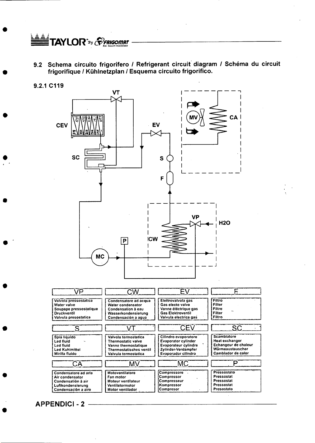
i T OY LOR *®v cPfRiGom itr
• ■ • • ■ ten aeam matblnax
9.2 Schema circuito frigorifero / Refrigerant circuit diagram / Schema du circuit
frigorifique / Kuhinetzplan / Esquema circuito frigorifico.
9.2.1 C119
CEV
VP
Valvola pressostatica
Water valve
Soupape pressostatique
Druckventil Wasserkondensiefung
Valvula presostatica
s
Spia liquido Valvola termostatica j
Led fluid Thermostatic valve j
Led fluid Vanne thermostatique j
Led Kuhimittel Thermostatisches ventll j
Mirilla fluido Valvula termostatica |
CA 1 MV
Condensatore ad aria
Air condensator
Condensatidn b air
Luftkondenslerung
Condensacibn a aire Motor ventilador ^
APPENDICI -2
.............
CW
_______
Condensatore ad acqua
Water condensator
Condensation i eau
Condensacibn a agua
V T . ■ ^ •
Motoventilatore
Fan motor
Moteur ventilateur
Ventilatormotor
J
Elettrovalvola gas
Gas electo valve
Vanne blectrique gas
Gas Elektroventil
Valvula electrica gas
Cllindro evaporators
Evaporator cylinder
Evaporateur cylindre
Zylinder-Verdampfer
Evaporador cilindro
MC
Compressors .
Compressor
Compresseur
Kompressor
Compresor
EV F
Filtro
Filter
Filtre
Filter
Filtro
[ _ SC . ■
Scambiatore
Heat exchanger
Echangeur de chaleur
Warmeaustauscher
Cambiador de calor
Pressostato
Pressostat
Pressostat
Pressostat
Presostato
P
Page 81
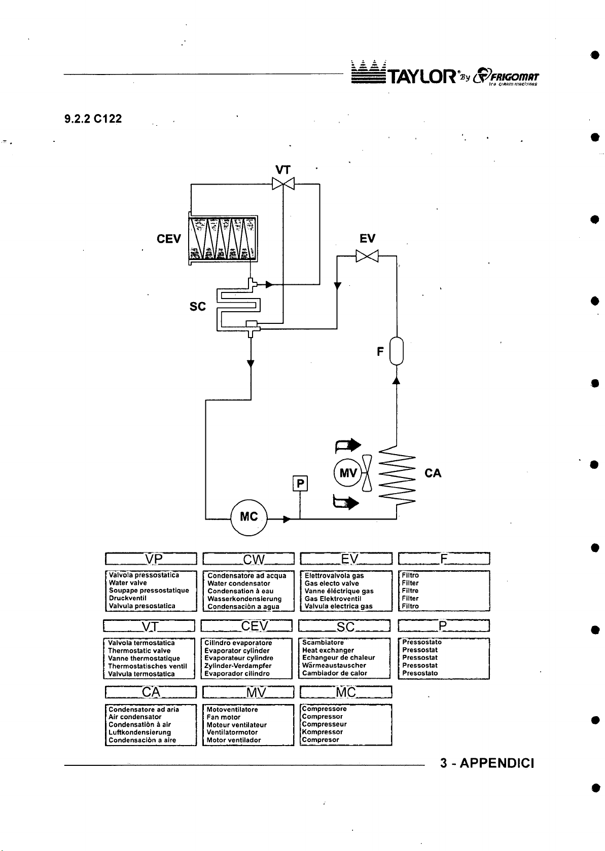
9.2.2 C122
|"TiflYLOR*®y (X^fRKom ur
VT
CEV
I VP
Valvola pressostatica
Water valve
Soupape pressostatique
Druckventil
Valvula presostatica
i . VT [
Valvola termostatica Cllindro evaporators
Thermostatic valve Evaporator cylinder
Vanne thermostatique
Thermostatlsches ventll
Valvula termostatica
[ CA
Condensatore ad aria Motoventllatore
Air condensator
Condensatidn ^ air
Luftkondenslerung Ventilatormotor
Condensacldn a aire
Condensatore ad acqua Elettrovalvola gas
Water condensator Gas electo valve
Condensation ^ eau Vanne ^l^ctrlque gas
Wasserkondenslerung Gas Elektroventll
Condensacion a agua
_____
Evaporateur cylindre
Zylinder-Verdampfer
Evaporador cllindro
I MV
Fan motor
Moteur ventilateur
Motor ventilador
X W
CEV_ _
r ^ E v
Valvula electrica gas Filtro
I
I
_____
Scambiatore
Heat exchanger
Echangeur de chaleur Pressostat
Warmeaustauscher
Cambiador de calor
s c
........
_____
I
MC
Compressors
Compressor
Compresseur
Kompressor
Compresor
CA
Filtro
Filter
Filtre
Filter
Pressostato
Pressostat
Pressostat
Presostato
.
...........
P !
3 - APPENDICI
Page 82
■ ■ Mfl cre a m m nth in o y
S p em aom ar
9.3 IMPIANTO ELETTRICO / ELECTRIC SYSTEM / GROUPE ELECTRIQUE /
ELEKTRISCHE ANLAGE / INSTALACION ELECTRICA
Lo schema elettrico funzionale ed il lay-out del box elettrico, specifico per ogni modello, e
collocate sulla parte esterna del coperchio del box stesso.
The functional wiring diagram and the electric box lay-out, different for each model are
located on the box cover.
Le schema electrique de fonctionnement et le lay-out de la boTte electrique, specifique
pour chaque modele, se trouve sur la partie exterieure du couvercle de cette boTte.
Das Elektroschema und das Lay-out der Elektro-Box ist auf dem Deckel der selben AufJen
angebracht und ist fur jedes Modell spezifisch bezogen.
El esquema electrico funcional y el lay-out de la caja electrica, especifico para cada
modelo, se halla en la parte externa de la tapa de la caja misma.
APPENDICI -4
Page 83
iW L O R - v Op/weo/n/w
9.4 RICAMBI / SPARE PARTS / PIECES DETACHEES / ERSATZTEILE / REPUESTOS
Per la richiesta delle parti di ricambio, si raccomanda di indicare sempre il numero di codice
relative e la denominazione riportata sulla legenda di ciascuna tavola. Si raccomanda inoltre di
comunicare sempre il modello ed il numero di matricola della macchina, nonche le caratteristiche
della stessa (voltaggio, frequenza e fasi), facilitando in tal modo I’identificazione del particolare.
Per ordinare la componentistica di ricambio del compressore indicare sempre anche il modello
specificate sulla targhetta del motore. In case di sostituzione di pezzi, richiedere solo ricambi
ORIGINALI TAYLOR ad un concessionario o ad un Rivenditore Autorizzato. TAYLOR declina ogni
responsabilit^ per danni a persone e/o cose derivanti dall’utilizzo di ricambi non originali.
For spare parts ordering, always mention the corresponding code number and the name reported
on each table caption. It is also recommended to always mention the machine model and the serial
number as well as the technical data (voltage, frequency and phases), to make the identification of
the component easier. To order spare parts for the compressor, always mention the model
specified on the motor nameplate. In case it is necessary to replace a component, always ask a
distributor or an authorized retailer for ORIGINAL spare parts. TAYLOR declines any liability for
damages to people and/or things due to employment of non-original spare parts.
En cas de demande de pieces d6tachees, Ton recommande vivement d’indiquer le num6ro de
code correspondent et la description figurant sur la I6gende de cheque tableau. L’on recommande
aussi de communiquer le module et le numero d’immatriculation de la machine, ainsi que ses
caracteristiques (voltage, frequence et phases), afin de faciliter I’identification de la piece. Pour
commander les composants de rechange du compresseur, il faut egalement indiquer le module qui
est specifie sur la plaque d'identification du moteur. En cas de remplacement de pieces, demander
uniquement des pieces detachees ORIGINALES TAYLOR en vous adressant a un
concessionnaire ou a un Revendeur Autoris6. TAYLOR decline toute responsabilite en cas de
dommages aux personnes ou aux choses qui d6riveraient de I'utilisation de pieces detachees non
originales.
Fur die Anfrage von Ersatzteilen raten wir Ihnen, immer die Kodenummer und die entsprechende
Benennung einer jeden Tafel mitzuteilen. Wir raten weiterhin, immer das Modell und die
Seriennummer der Maschine mitzuteilen als auch die Maschineneigenschaften (Voltleistung,
Frequenz und Phasen), urn die Erkennung von Besonderheiten zu vereinfachen. Urn Ersatzteile
des Kompressors zu bestellen, muB man auch das direkte Modell angeben, welches auf dem
Motorschild verzeichnet ist. Im Austauschfall von Teilen nur Originalteilen der Firma Firgomat beim
Konzessionar Oder autorisiertem Wiederverkaufer anfragen. Die Firma TAYLOR ist von jeglichem
Schadensersatz an Personen u/o Gegenstanden entbunden, die auf den Einsatz von nicht
originalen Ersatzteilen zuruckzufuhren sind.
Para la peticion de las partes de recambio, se recomienda indicar siempre el numero de codigo
relative y la denominacibn indicada en la leyenda de cada tabla. Ademas, se recomienda
comunicar siempre el modelo y el numero de matricula de la mbquina, asi como las caracteristicas
de la misma (voltaje, frecuencia y fases), facilitando de esta manera la identificacion de la parte.
Para pedir los componentes de recambio del compresor indicar siempre tambibn el modelo
especificado en al placa del motor. En case de sustitucibn de piezas, pedir sblo recambios
ORIGINALES TAYLOR a un concesionario o a un Revendedor Autorizado. TAYLOR declina
cualquier responsabilidad por dahos a personas y/o cosas derivados del uso de recambios no
originales.
5 - APPENDICI
Page 84
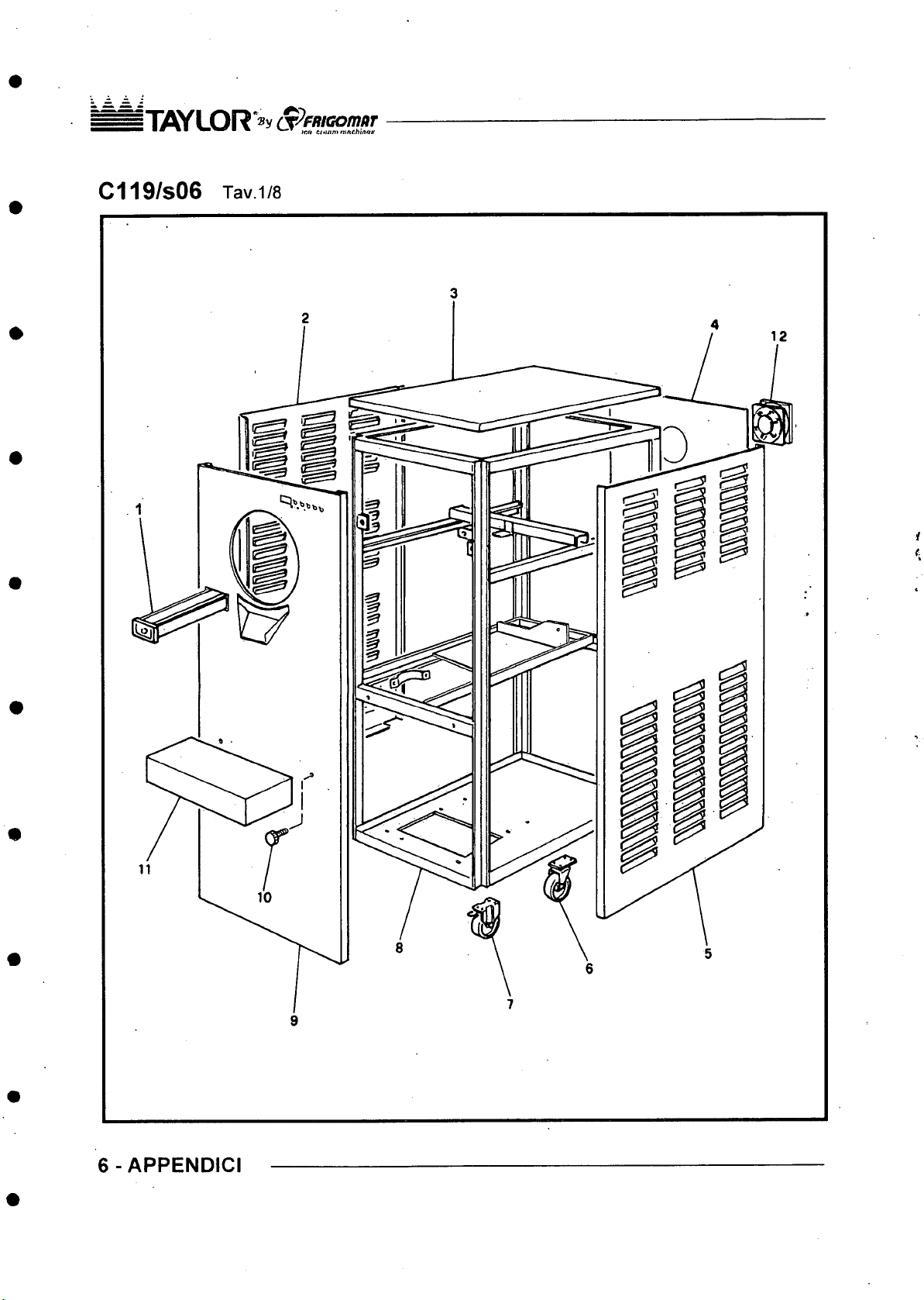
|"nW L O R *® y S ^ fR iG o m tir
" • * ■ m cinan tninch in fiK
C119/S06 Tav1/8
6-APPENDICI
Page 85
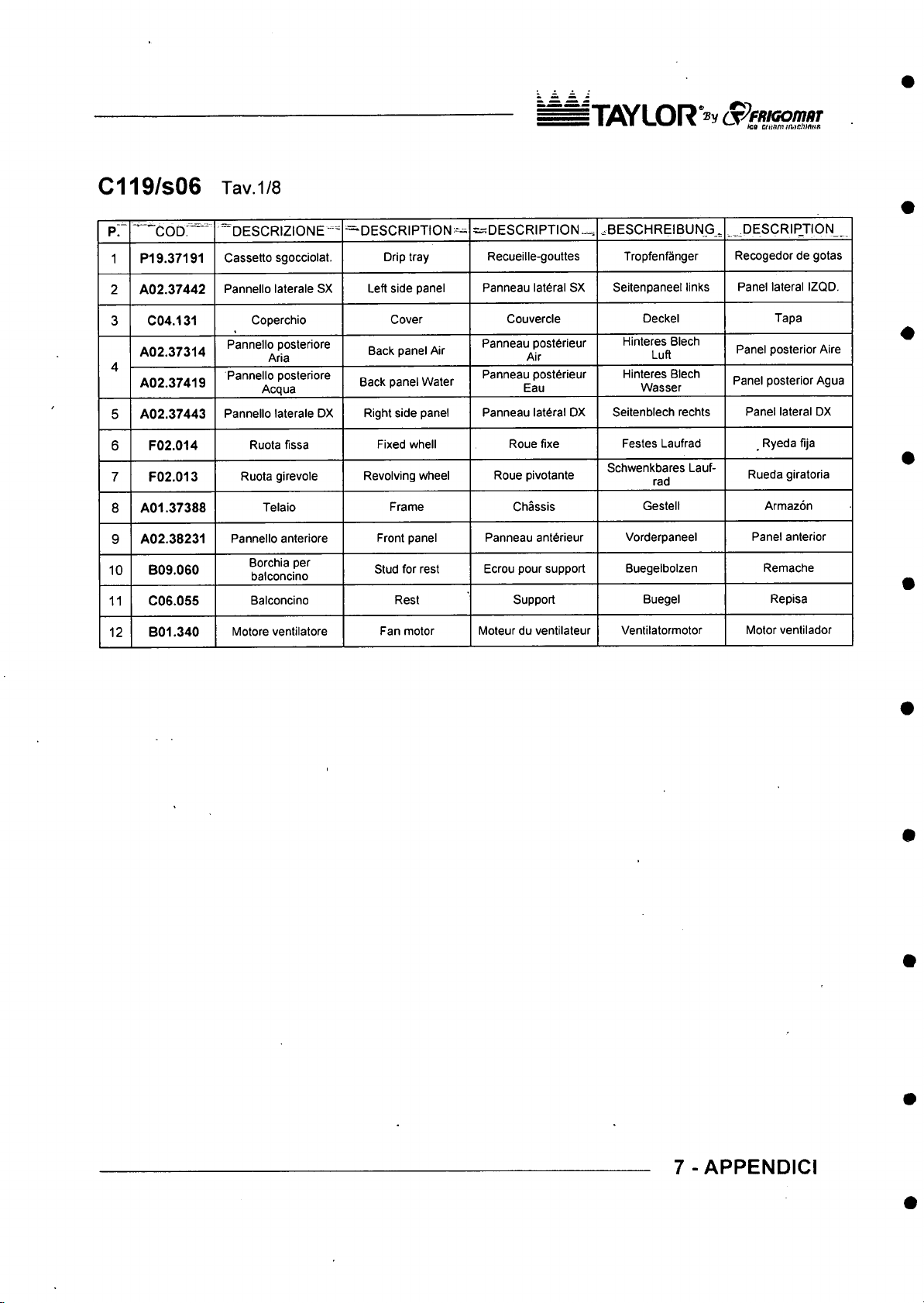
C119/S06 Tav1/8
IT O Y L O R S ^pn iG on m
■ Hi9 aitmui^-irJnnuR
‘^ ’ 'COD“
p;
PI 9.37191
1
A02.37442
2
3 C04.131
A02.37314
4
A02.37419
A02.37443
5
F02.014
6
7 F02.013
A01.37388
8
A02.38231
9
B09.060
10
C06.055
11
B01.340
12
” D ESCRIZIONE“ =^
Cassetto sgocciolat.
Pannello laterale SX
Coperchio
Pannello posteriore
Aria
Pannello posteriore
Acqua
Pannello laterale DX
Ruota fissa
Ruota girevole
Telaio
Pannello anteriore
Borchia per
balconcino
Balconcino
Motore ventilatore
— DESCR IP TION^
Drip tray
Left side panel
Cover
Back panel Air
Back panel Water
Right side panel
Fixed w/hell
Revolving wheel
Frame Chassis
Front panel
Stud for rest
Rest
Fan motor
=:sDESCRIPTION.^
Recueille-gouttes
Panneau lateral SX
Couvercle
Panneau post6heur
Air
Panneau post6rieur
Eau
Panneau lateral DX
Roue fixe
Roue pivotante
Panneau anterieur Vorderpaneel
Ecrou pour support
Support Buegel
Moteur du ventilateur
.B ESCHREIBU NG,
Tropfenfanger
Seitenpaneel links
Deckel
Hinteres Blech
Luft
Hinteres Blech
Wasser
Seitenblech rechts
Festes Laufrad
Schwenkbares Lauf
rad
Gestell Armazon
Buegelbolzen
Ventilatormotor Motor ventilador
._OES CRIPJIO N_
Recogedor de gotas
Panel lateral IZQD.
Tapa
Panel posterior Aire
Panel posterior Agua
Panel lateral DX
Ryeda fija
Rueda giratoria
Panel anterior
Remache
Repisa
7 - APPENDICI
Page 86
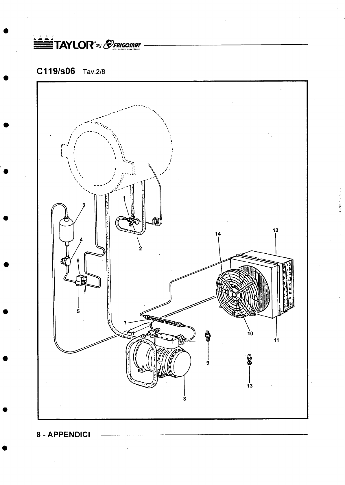
i1iflY LO R *® y S ^ fi tiG o m itr
" • • ■ m % i,-» afinrn ntfiehlnax
C119/S06 Tav2/8
8-APPENDICI
Page 87
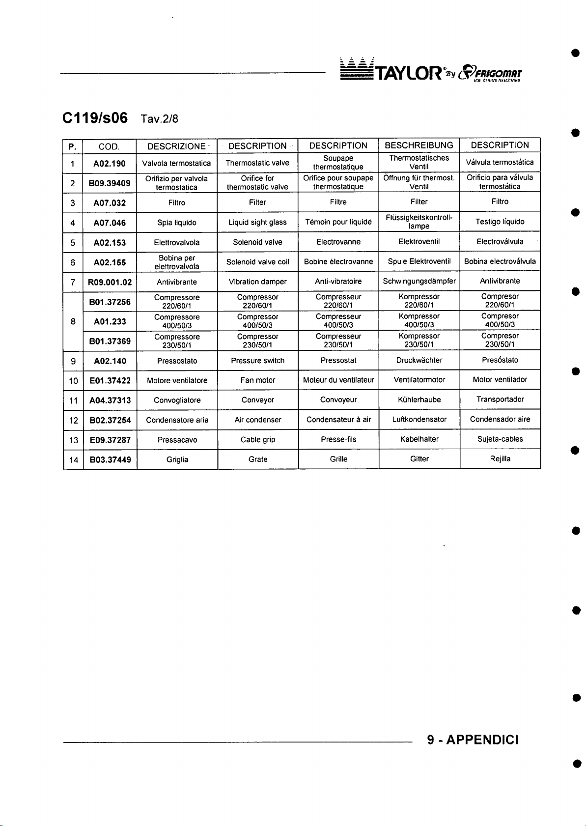
C119/S06 Tav2/8
ITflYL OR o P fR K ionm r
■ m:b e/ar3nrfthJt/:/rt«R
1
2
3
COD.
A02.190
B09.39409
A07.032
p.
4 A07.046
5 A02.153
6 A02.155
R09.001.02
7
B01.37256
8
A01.233
B01.37369
A02.140
g
E01.37422
10
A04.37313
11
B02.37254
12
DESCRIZIONE^
Valvola termostatica
Orifizio per valvola
termostatica
Filtro
Spia liquido
Elettrovalvola
Bobina per
elettrovalvola
Antivibrante
Compressore
220/60/1
Compressore
400/50/3
Compressore
230/50/1
Pressostato
Motore ventilatore
Convogliatore
Condensatore aria
DESCRIPTION
Thermostatic valve
Orifice for
thermostatic valve
Filter
Liquid sight glass
Solenoid valve
Solenoid valve coil
Vibration damper
Compressor
220/60/1
Compressor
400/50/3
Compressor
230/50/1
Pressure switch
Fan motor
Conveyor
Air condenser
DESCRIPTION
Soupape
thermostatique
Orifice pour soupape
thermostatique
Filtre
Tdmoin pour liquide
Electrovanne
Bobine 6lectrovanne
Anti-vibratoire
Compresseur
220/60/1
Compresseur
400/50/3
Compresseur
230/50/1
Pressostat
Moteur du ventilateur
Convoyeur
Condensateur d air
BESCHREIBUNG
Thermostatisches
Ventil
Offnung fiir thermost.
Ventil
Filter Filtro
Fliissigkeitskontroll-
lampe
Elektroventil
Spule Elektroventil
Schwingungsdampfer Antivibrante
Kompressor
220/60/1
Kompressor
400/50/3
Kompressor
230/50/1
Druckwachter Presostato
Ventilatormotor
Kiihlerhaube
Luftkondensator Condensador aire
DESCRIPTION
Valvula termostatica
Orificio para valvula
termostatica
Testigo li'quido
Electrovalvula
Bobina electrovalvula
Compresor
220/60/1
Compresor
400/50/3
Compresor
230/50/1
Motor ventilador
Transportador
13
14
E09.37287
B03.37449
Pressacavo
Griglia
Cable grip
Grate
Presse-fils
Grille
Kabelhalter Sujeta-cables
Gitter Rejilla
9 - APPENDICI
Page 88
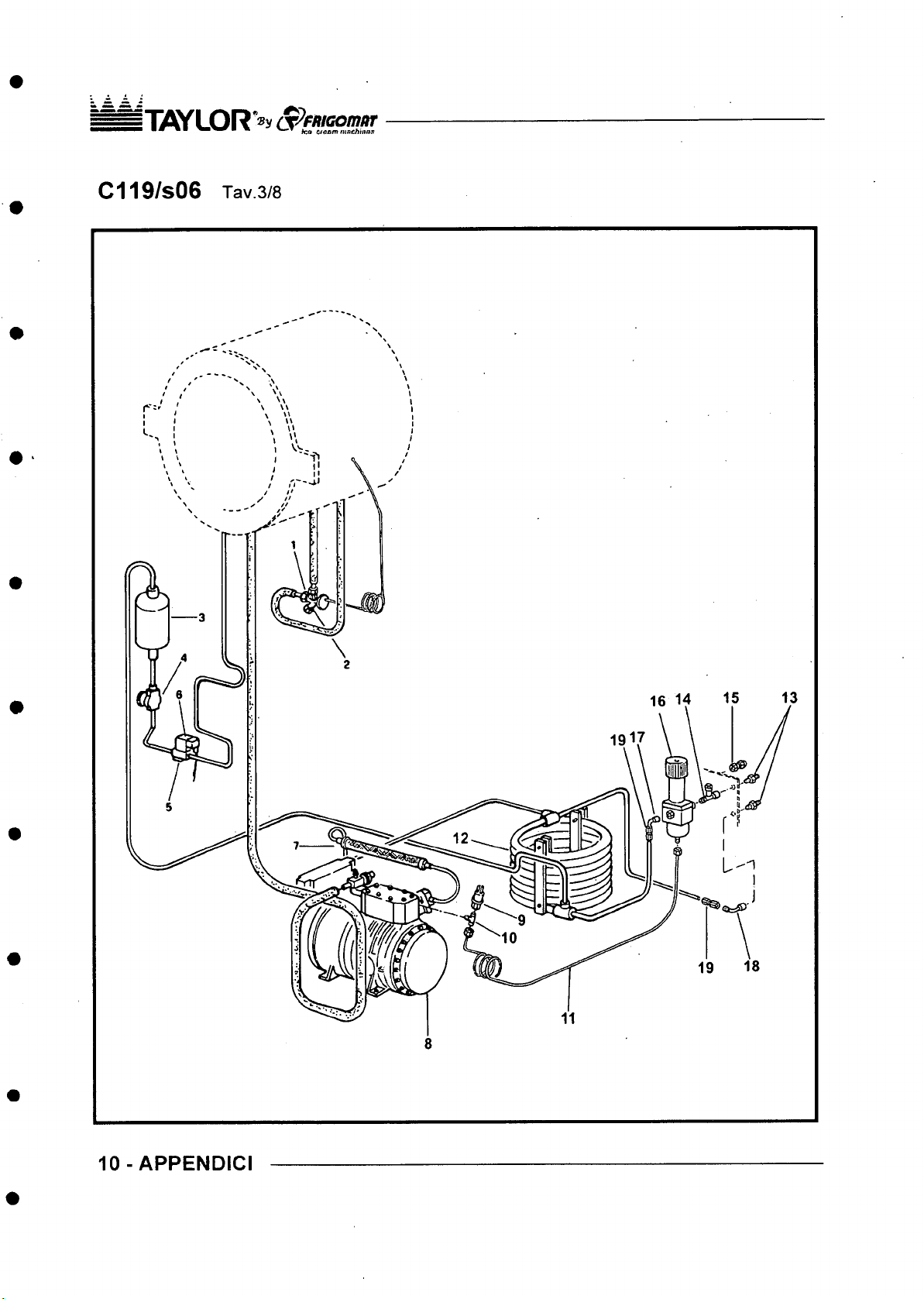
il/C f LOR*®y S^fftiGomar
■ ■» • ■ machinaa
C119/S06 Tav3/8
10 - APPENDICI
Page 89
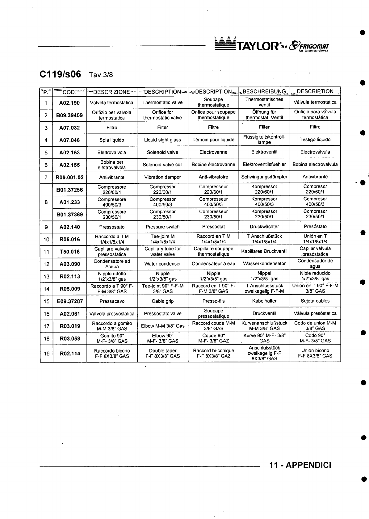
C119/S06 Tav3/8
liy S Y L O R
■ *■ ■ m w» ten en!Rn\tMCiWHlH
— c o d ;“
^ p r
A02.190
1
B09.39409
2
A07.032
3
4 A07.046
A02.153
5
A02.155
6
R09.001.02
7
B01.37256
8
A01.233
B01.37369
A02.140
9
R06.016
10
T50.016
11
A03.090
12
R02.113
13
R05.009
14
E09.37287
15
16 A02.061
17 R03.019
18 R03.058
R02.114
19
~DES CRIZION E='-
Valvola termostatica
Orifizio per valvola
termostatica
Filtro
Spia liquido
Elettrovalvola
Bobina per
elettrovalvola
Antivibrante
Compressore
220/60/1
Compressore
400/50/3
Compressore
230/50/1
Pressostato
Raccordo a T M
1/4x1/8x1/4
Caplllare valvola
pressostatica
Condensatore ad
Acqua
Nippio ridotto
1/2”x3/8” gas
Raccordo a T 90° F-
F-M 3/8" GAS
Pressacavo
Valvola pressostatica Pressostatc valve
Raccordo a gomito
M-M 3/8" GAS
Gomito 90°
M-F- 3/8” GAS
Raccordo bicono
F-F 8X3/8" GAS
--D ES CR IP TION-^
Thermostatic vaive
Orifice for
thermostatic valve
Filter Filtre
Liquid sight glass
Solenoid valve
Solenoid valve coil
Vibration damper
Compressor
220/60/1
Compressor
400/50/3
Compressor
230/50/1
Pressure switch
Tee-joint M
1/4x1/8x1/4
Capillary tube for
water valve
Water condenser
Nipple
1/2”x3/8” gas
Tee-joint 90° F-F-M
3/8“ GAS
Cable grip
Elbow M-M 3/8” Gas
Elbow 90°
M-F- 3/8” GAS
Double taper
F-F 8X3/8” GAS
= DESCRIPTION=..
Soupape
thermostatique
Orifice pour soupape
thermostatique
T6moin pour liquide
Electrovanne
Bobine 6lectrovanne
Anti-vibratoire
Compresseur
220/60/1
Compresseur
400/50/3
Compresseur
230/50/1
Pressostat
Raccord en T M
1/4x1/8x1/4
Capillaire soupape
thermostatique
Condensateur d eau
Nipple
1/2”x3/8” gas
Raccord en T 90° F-
F-M 3/8" GAS
Presse-fils
Soupape
pressostatique
Raccord coud6 M-M
3/8" GAS
Coude 90°
M-F- 3/8" GAZ
Raccord bi-conique
F-F 8X3/8" GAZ
iBESC HREIBUNG ^
Thermostatisches
ventil
Offnung fiir
thermostat. Ventil
Filter Filtro
Flussigkeitskontroll-
lampe
Elektroventil
Elektroventiisfuehler
Schwingungsdampfer
Kompressor
220/60/1
Kompressor
400/50/3
Kompressor
230/50/1
Druckwachter Presostato
T AnschluBstuck
1/4x1/8x1/4
Kapillares Druckventil
Wasserkondensator
Nippel
1/2”x3/8” gas
T Anschlussstuck
zweikegelig F-F-M
Kabelhalter
Druckventil VSIvula presbstatica
Kurvenanschlulistuck
M-M 3/8” GAS
Kurve 90° M-F- 3/8”
GAS
AnschlulistOck
zweikegelig F-F
8X3/8” GAS
,_.,PESCRIP JI0N^,
Valvula termostatica
Orificio para valvula
termostatica
Testigo Ifquido
Electrovalvula
Bobina electrovalvula
Antivibrante
Compresor
Compresor
Compresor
Union en T
1/4x1/8x1/4
Capilar valvula
presostatica
Condensadorde
Niple reducido
1/2”x3/8” gas
Union en T 90° F-F-M
Sujeta-cables
Codo de union M-M
M-F- 3/8” GAS
Unibn bicono
F-F 8X3/8” GAS
220/60/1
400/50/3
230/50/1
agua
3/8" GAS
3/8" GAS
Codo 90°
11 - APPENDICI
Page 90
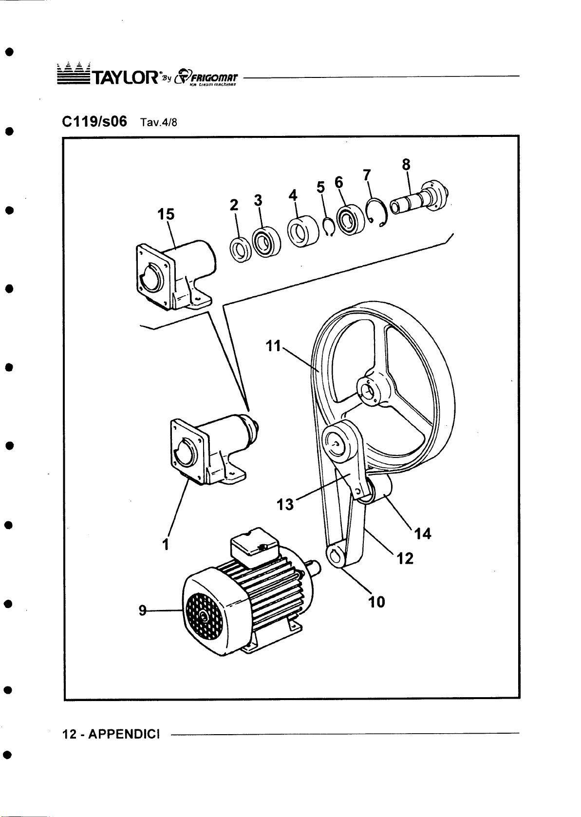
liy S Y L O R S p P B iG o m iiT
■ fc n ttt t v m m nchinna
C119/S06 Tav4/8
12 - APPENDICI
Page 91
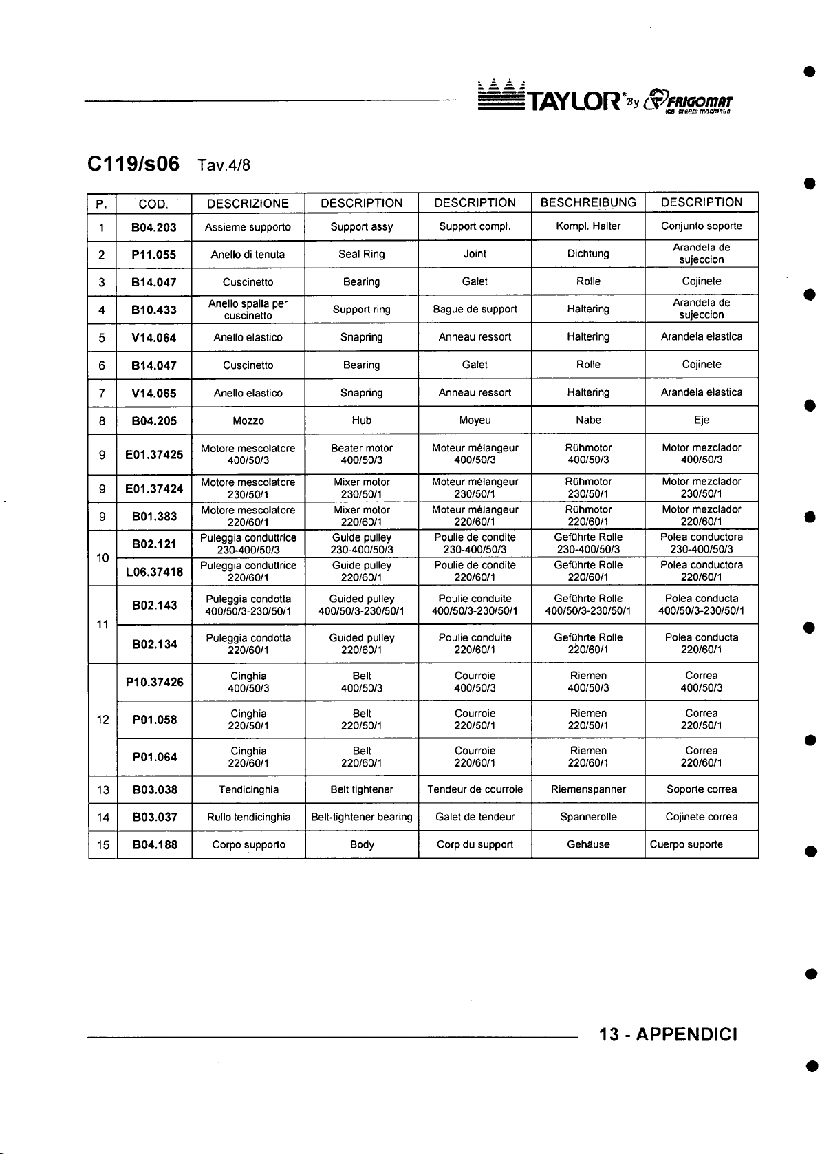
C119/S06 Tav4/8
I TiOYLOR ^^f»icofl7/w
■ le a aa a t ttm ^c / u n a a
p. COD.
1 B04.203
P11.055
2
3 B14.047
4 B10.433
V14.064
5
B14.047
6
7
V14.065
8 B04.205
E01.37425
9
E01.37424
9
B01.383
9
B02.121
10
L06.37418
B02.143
11
B02.134
DESCRIZIONE
Assieme supporto
Anello di tenuta
Cuscinetto
Anello spalla per
cuscinetto
Anello elastico
Cuscinetto
Anello elastico
Mozzo
Motore mescolatore
400/50/3
Motore mescolatore
230/50/1
Motore mescolatore
220/60/1
Puleggia conduttrice
230-400/50/3
Puleggia conduttrice
220/60/1
Puleggia condotta
400/50/3-230/50/1
Puleggia condotta
220/60/1
DESCRIPTION
Support assy
Seal Ring
Bearing
Support ring
Snapring
Bearing Galet
Snapring Anneau ressort
Hub
Beater motor
400/50/3
Mixer motor
230/50/1
Mixer motor
220/60/1
Guide pulley
230-400/50/3
Guide pulley
220/60/1
Guided pulley
400/50/3-230/50/1
Guided pulley
220/60/1
DESCRIPTION BESCHREIBUNG
Support compl. KompI, Halter Conjunto soporte
Bague de support
Anneau ressort
Moteur m6langeur
400/50/3
Moteur m6langeur
230/50/1
Moteur mSlangeur
220/60/1
Poulie de condite
230-400/50/3
Poulie de condite
220/60/1
Poulie conduite
400/50/3-230/50/1
Poulie conduite
220/60/1
Joint
Galet Rolle
Moyeu Nabe
Dichtung
Haltering
Haltering Arandela elastica
Rolle Cojinete
Haltering
ROhmotor
400/50/3
ROhmotor
230/50/1
ROhmotor
220/60/1
GefUhrte Rolle
230-400/50/3
GefOhrte Rolle
220/60/1
GefOhrte Rolle
400/50/3-230/50/1
Gefuhrte Rolle
220/60/1
DESCRIPTION
Arandela de
sujeccion
Cojinete
Arandela de
sujeccion
Arandela elastica
Eje
Motor mezclador
400/50/3
Motor mezclador
230/50/1
Motor mezclador
220/60/1
Polea conductora
230-400/50/3
Polea conductora
220/60/1
Polea conducta
400/50/3-230/50/1
Polea conducta
220/60/1
PI 0.37426
12
P01.058
P01.064
B03.038
13
14 B03.037
B04.188
15
Cinghia
400/50/3
Cinghia
220/50/1
Cinghia
220/60/1
Tendicinghia
Rullo tendicinghia Belt-tightener bearing Galet de tendeur
Corpo supporto
Belt
400/50/3
Belt
220/50/1
Belt
220/60/1
Belt tightener Tendeur de courroie Riemenspanner Soporte correa
Body Corp du support Gehduse Cuerpo suporte
Courroie
400/50/3
Courroie
220/50/1
Courroie
220/60/1
Riemen
400/50/3
Riemen
220/50/1
Riemen
220/60/1
Spannerolle Cojinete correa
Correa
400/50/3
Correa
220/50/1
Correa
220/60/1
13 - APPENDICI
Page 92
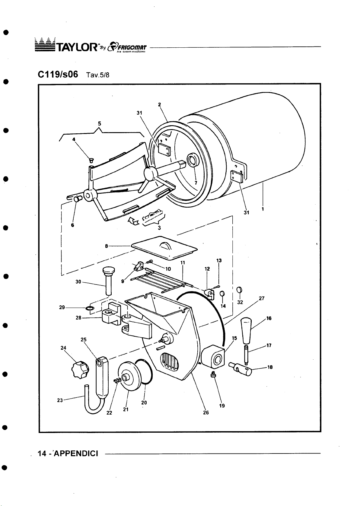
i“IiflY LO R *® y S ^ F R iG o m o T
* ■ " • ■ ' ' ' ■ * h'.a tia am ninth,n o.s
14 - APPENDIC I
Page 93
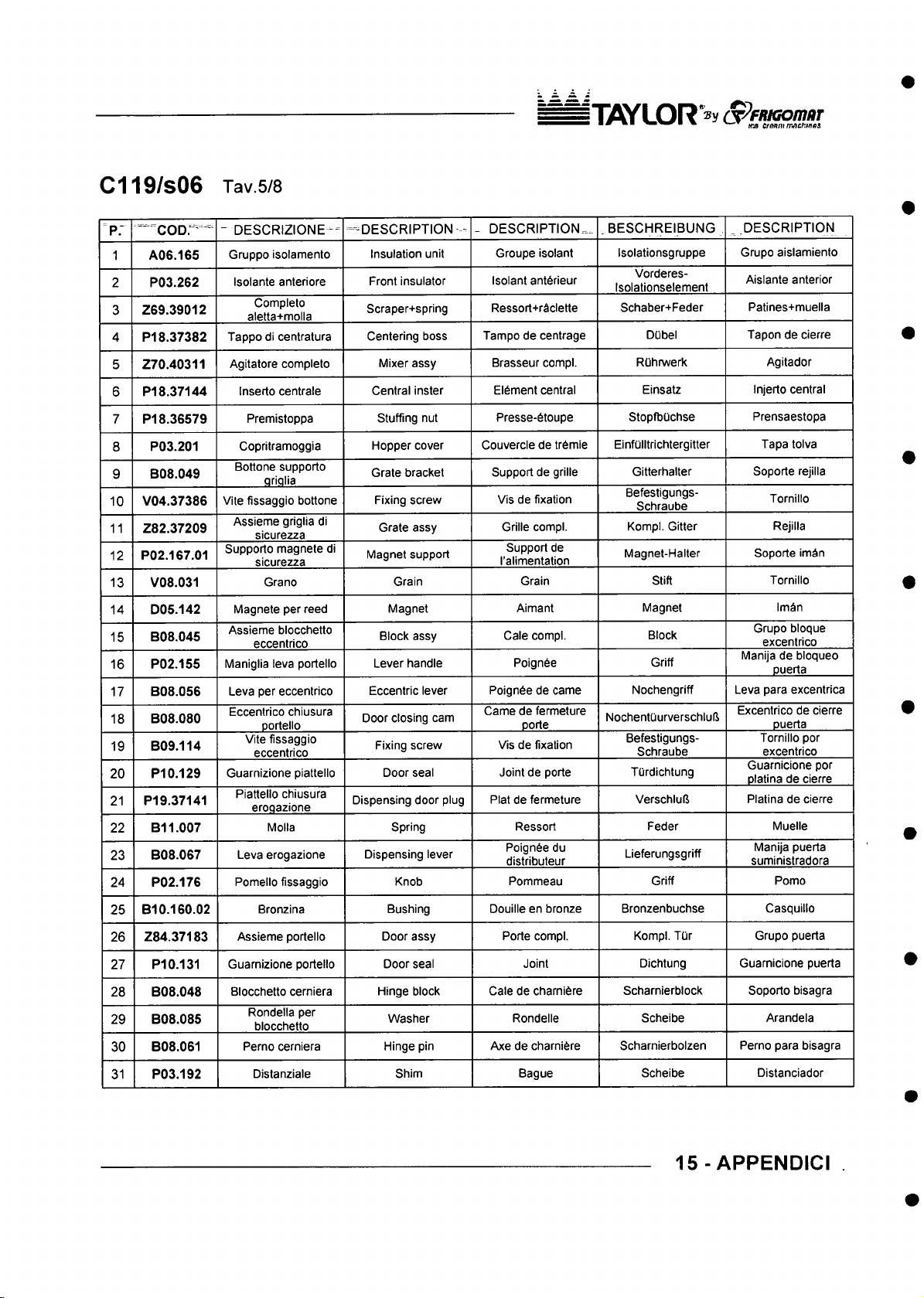
C119/S06 Tav5/8
iT 7SYL0R"® y S ^ ffU G o m a T
■ m WT c/aflm/rw5£/:i/?es
“ coor^ ^
"p :
A06.165
1
P03.262
2
Z69.39012
3
4 P18.37382
5 Z70.40311
PI 8.37144
6
P18.36579
7
P03.201
8
B08.049
9
V04.37386
10
Z82.37209
11
P02.167.01
12
V08.031
13
D05.142
14
B08.045
15
P02.155
16
B08.056
17
B08.080
18
B09.114
19
PI 0.129
20
PI 9.37141
21
B11.007
22
B08.067
23
24 P02.176
B10.160.02
25
26 Z84.37183
27 P10.131
B08.048
28
B08.085
29
B08.061
30
P03.192
31
- DESCRIZIONE-
Gruppo isolamento
Isolante anteriore
Completo
aletta+molla
Tappo di centratura
Agitatore completo
Inserto centrale
Premistoppa
Copritramoggia
Bottone supporto
qrialia
Vite fissaggio bottone
Assieme griglia di
sicurezza
Supporto magnete di
sicurezza
Grano
Magnete per reed
Assieme blocchetto
eccentrico
Maniglia leva portello
Leva per eccentrico
Eccentrico chiusura
oortello
Vite fissaggio
eccentrico
Guarnizione piattello
Piattello chiusura
eroaazione
Molla
Leva erogazione
Pomello fissaggio
Bronzina
Guarnizione portello
Blocchetto cerniera
Rondella per
blocchetto
Perno cerniera
Distanziale
-DESCRIPTION -
Insulation unit
Front insulator
Scraper+spring
Centering boss
Mixer assy
Central inster
Stuffing nut
Hopper cover
Grate bracket
Fixing screw
Grate assy
Magnet support
Grain
Magnet
Biock assy
Lever handle
Eccentric lever
Door closing cam
Fixing screw
Door seal
Dispensing door plug Plat de fermeture
Spring
Dispensing lever
Knob
Bushing Douille en bronze
Door assy
Door seal
Hinge block
Washer Rondelle
Hinge pin
Shim Bague
- DESCRIPTION^ .BESCHREIBUNG
Groupe isolant
Isolant anterieur
Ressort+raclette
Tampo de centrage
Brasseur compl.
Element central
Presse-dtoupe
Couvercle de tr6mie
Support de grille
Vis de fixation
Grille compl.
Support de
I’alimentation
Grain
Aimant
Cale compl.
Poignde
Poign6e de came
Came de fermeture
porte
Vis de fixation
Joint de porte
Ressort
Poignde du
distributeur
Pommeau
Porte compl.
Joint
Cale de charnifere
Axe de charni^re
_ DESCRIPTION
Isolationsgruppe
Vorderes-
Isolationselement
Schaber+Feder
DUbel
ROhrwerk
Einsatz Injerto central
StopfbOchse
EinfOlltrichtergitter Tapa tolva
Gitterhalter Soporte rejilla
Befestigungs-
Schraube
Kompl. Gitter Rejilla
Magnet-Halter Soporte imSn
Stift
Magnet
Block
Griff
Nochengriff Leva para excentrica
NochentCiurverschluli
Befestigungs-
Schraube
TUrdichtung
Verschluli
Feder Muelle
Lieferungsgriff
Griff Porno
Bronzenbuchse
Kompl. T(jr Grupo puerta
Dichtung Guarnicione puerta
Scharnierblock
Scheibe Arandela
Scharnierbolzen Perno para bisagra
Scheibe
Grupo aislamiento
Aislante anterior
Patines+muella
Tapon de cierre
Agitador
Prensaestopa
Tornillo
Tornillo
Im^in
Grupo bloque
excentrico
Manija de bloqueo
puerta
Excentrico de cierre
Duerta
Tornillo por
excentrico
Guarnicione por
platina de cierre
Platina de cierre
Manija puerta
suministradora
Casquillo
Soporto bisagra
Distanciador
15 - APPENDICI
Page 94
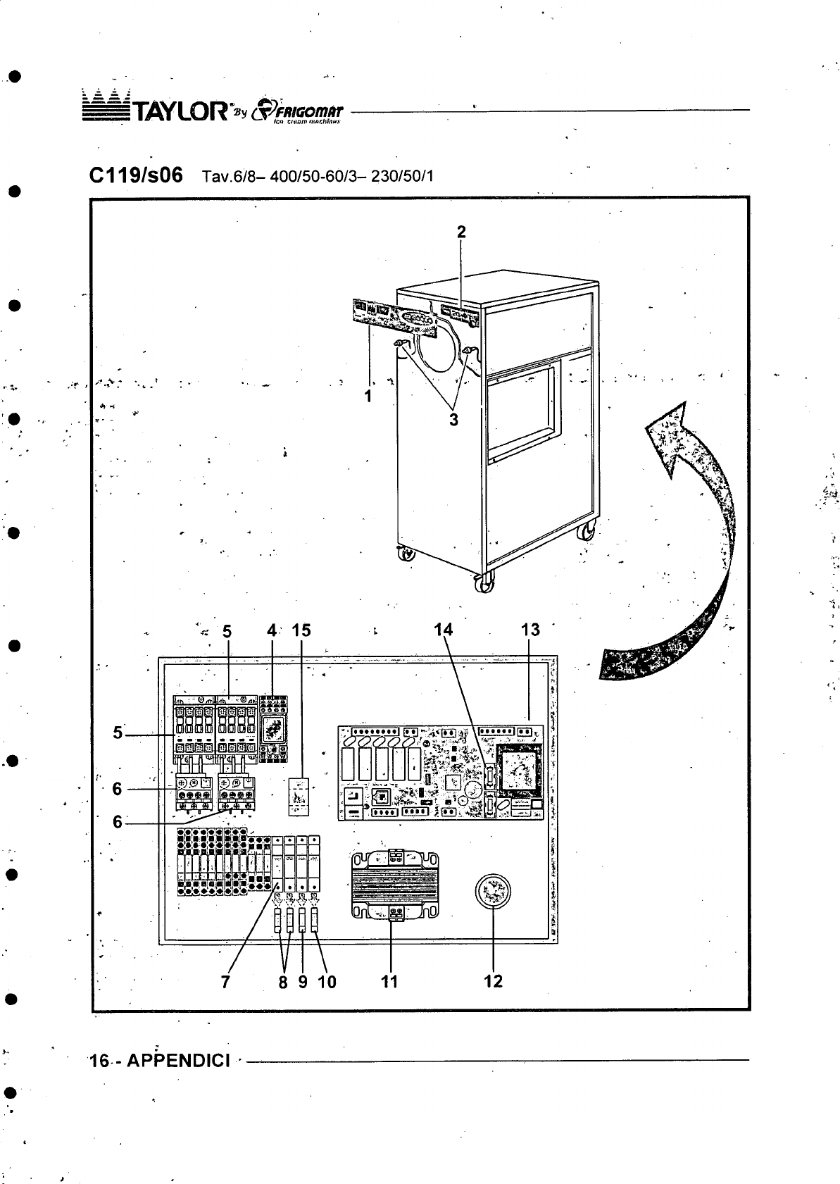
ifi fl Y LOR S^F/iiG om itr
• ^ V—▼ c/iiow mnchlnux
C119/s06 Tav.6/8- 400/50-60/3- 230/50/1
16 - APPENDICI
Page 95
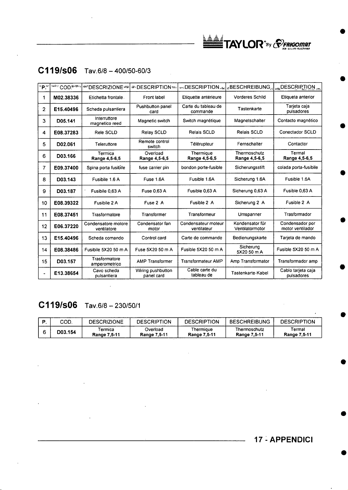
C119/s06 Tav.6/8 - 400/50-60/3
IT flY L O R ^ y S ^ F R K io m tiT
■pr ~" ^C O D .= ^
1 M 02 .38336
2 E l 5.404 9 6
D05.141
3
4 E08.37283
D02.061
5
6 D 03.166
7 E09.37400
D03.143
8
D03.187
9
E08.39322
10
11 E08.37451
E06.37220
12
E15.40496
13
E08.38486
14
D03.15 7
15
E13.38654
-
— D ESC RIZIO NE™
Etichetta frontale
Scheda pulsantiera
Interruttore
magnetico reed
Rele SOLD
Teleruttore
Termica
Range 4,5-6,5
Spina porta fusibile
Fusibile 1.6 A Fuse 1.6A
Fusibile 0,63 A
Fusibile 2 A
Trasformatore
Condensatore motore
ventilatore
Scheda comando
Fusibile 5X20 50 m A
Trasformatore
amperometrico
Cavo scheda
pulsantiera
— DES CRIPTION
Pushbutton panel
Magnetic switch
Remote control
Range 4,5-6,5
fuse carrier pin bondon porte-fusible
Condensator fan
Fuse 5X20 50 m A
AMP Transformer
Wiring pushbutton
^;D E S CR IP T IO N ^ i:B ESC HR EIB UN G. ^DE SCR IPJ ION ...,^
Front label
card
Relay SCLD
switch
Overload
Fuse 0,63 A Fusible 0,63 A
Fuse 2 A Fusible 2 A
Transformer
motor
Control card Carte de commande
panel card
Etiquette ant6rieure
Carte du tableau de
commande
Switch magnStique
Relais SCLD Relais SCLD
T6l6rupteur
Thermique
Range 4,5-6,5
Fusible 1.6A
Transformeur
Condensateur moteur
ventilateur
Fusible 5X20 50 m A
Transformateur AMP Amp Transformator Transformador amp
Cable carte du
tableau de
Vorderes Schild Etiqueta anterior
Tastenkarte
Magnetschalter
Fernschalter Contactor
Thermoschutz
Range 4,5-6,5
Sicherungsstift colada porta-fusibile
Sicherung 1.6A Fusible 1.6A
Sicherung 0,63 A Fusible 0,63 A
Sicherung 2 A Fusible 2 A
Umspanner Trasformador
Kondensator fur
Ventilatormotor
Bedienungskarte Tarjeta de mando
Sicherung
5X20 50 m A
Tastenkarte-Kabel
Tarjeta caja
pulsadores
Contacto magn6tico
Conectador SCLD
Termal
Range 4,5-6,5
Condensador por
motor ventilador
Fusible 5X20 50 m A
Cablo tarjeta caja
pulsadores
C119/s06 Tav.6/8 - 230/50/1
P.
COD. DES CRIZIO NE DES CRIPTION
6 D03.154
Termica
Range 7,5-11
Overload
Range 7,5-11
DES CRIPTION
Thermique
Range 7,5-11
BES CH REIB UNG
Thermoschutz
Range 7,5-11
17-APPENDICI
DES CRIPTION
Termal
Range 7,5-11
Page 96
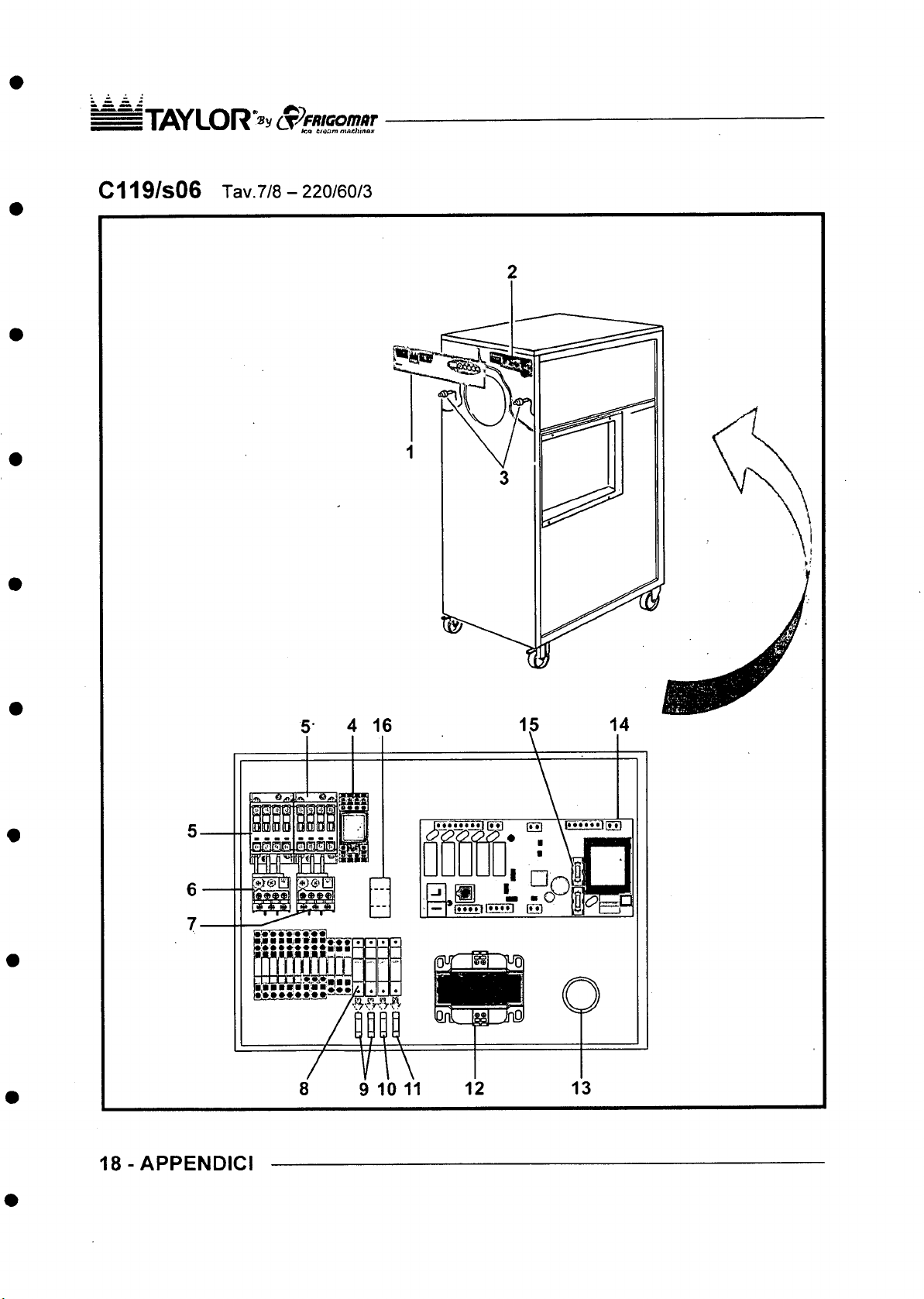
ITflYL OR S ^^ffio o m ar
■ ■ ■■ ■ * ’ lea Cfoam niAChinas
C119/s06 Tav.7/8 - 220/60/3
6
7-
1 8 - APPEN DICI
E}0SE3£
nr^Pfrn
B M E ie
9 10 11
Page 97
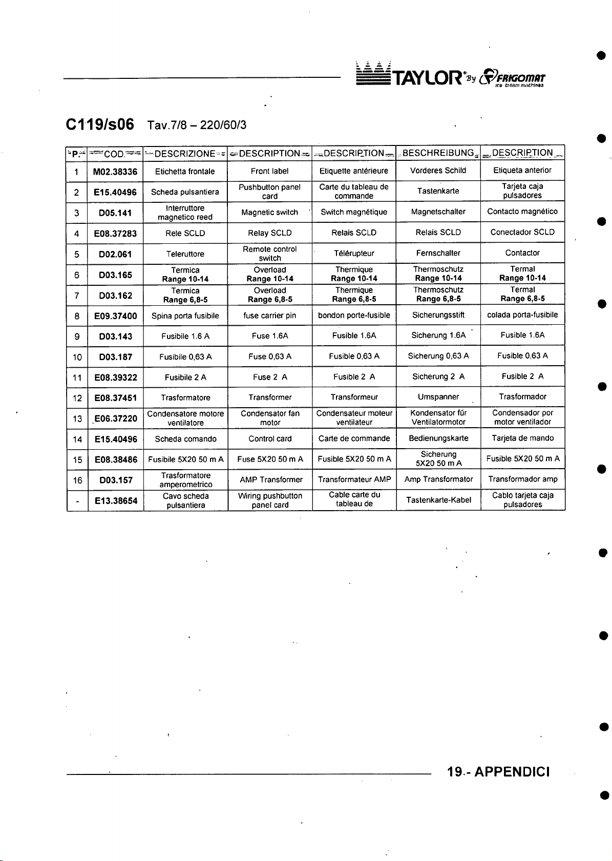
C119/s06 Tav.7/8 - 220/60/3
i“|y V y L O R ‘®y S ^ fn K o m a T
■ ■% \-.T c/nmt»nw£W»M
-p ." = C O D .= = ^
M02 .38336
1
E l 5.4049 6
2
D05.141
3
4 E08.37283
D02.061
5
D03.165
6
7 D 03.162
E09.37400
8
D03.143
9
D03.187
10
E08.39322
11
E08.37451
12
E06.37220
13
14 E l 5.40496
E08.38486
15
D03.157
16
E l 3.38654
-
=-“ DESGRIZIONE-=
Etichetta frontale
Scheda pulsantiera
Interruttore
magnetico reed
Rele SOLD
Teleruttore
Termica
Range 10-14
Termica
Range 6,8-5
Spina porta fusibile
Fusibiie 1.6 A
Fusibiie 0,63 A
Fusibile 2 A
Trasformatore
Condensatore motore
ventilatore
Scheda comando
Fusibile 5X20 50 m A
Trasformatore
amperometrico
Cavo scheda
pulsantiera
^D E S C R IP T IO N ^
Front label Etiquette ant6rieure
Pushbutton panel
card
Magnetic switch
Relay SCLD
Remote control
switch
Overload
Range 10-14
Overload
Range 6,8-5
fuse carrier pin
Fuse 1.6A
Fuse 0,63 A
Fuse 2 A
Transformer Transformeur
Condensator fan
motor
Controi card
Fuse 5X20 50 m A
AMP Transformer
Wiring pushbutton
panel card
^DESCRIP.TION=:r,
Carte du tabieau de
commande
Switch magn6tique
Relais SCLD
T6i6rupteur
Thermique
Range 10-14
Thermique
Range 6,8-5
bondon porte-fusibie
Fusible 1.6A
Fusible 0,63 A
Fusible 2 A
Condensateur moteur
ventilateur
Carte de commande
Fusible 5X20 50 m A
Transformateur AMP
Cable carte du
tableau de
,.BESC HREIBUNG , ^D E SCR LP JIO N _
Vorderes Schild
Tastenkarte
Magnetschalter Contacto magndtico
Relais SCLD
Fernschalter
Thermoschutz
Range 10-14
Thermoschutz
Range 6,8-5
Sicherungsstift
Sicherung 1.6A Fusible 1.6A
Sicherung 0,63 A Fusible 0,63 A
Sicherung 2 A Fusible 2 A
Umspanner Trasformador
Kondensator fur
Ventilatormotor
Bedienungskarte Tarjeta de mando
Sicherung
5X20 50 m A
Amp Transformator Transformador amp
Tastenkarte-Kabel
Etiqueta anterior
Tarjeta caja
pulsadores
Conectador SCLD
Contactor
Termal
Range 10-14
Termal
Range 6,8-5
colada porta-fusibile
Condensador por
motor ventilador
Fusible 5X20 50 m A
Cablo tarjeta caja
pulsadores
19 - APPENDICI
Page 98
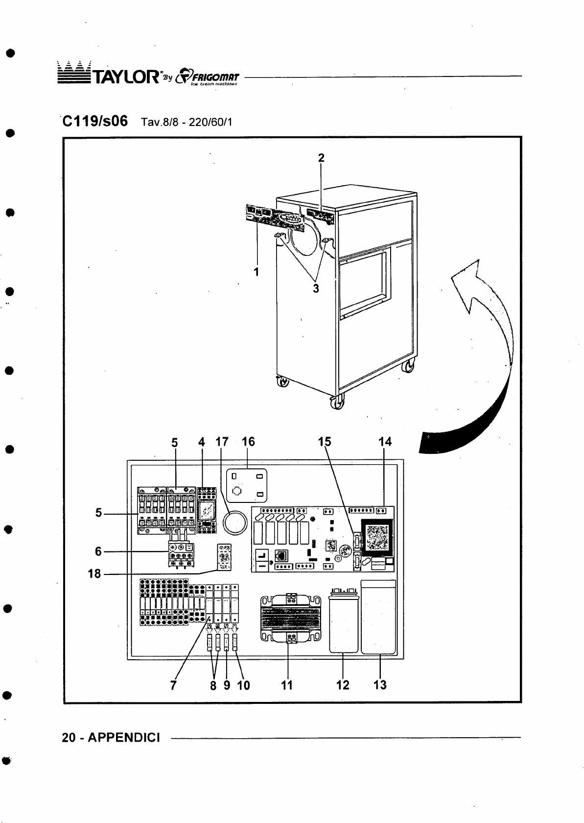
jT if lY L O R* » y op/w/com/w
C119/s06 Tav.8/8 - 220/60/1
18
5 4 17 16
6
8 9 10
20-A PP E ND ICI
Page 99
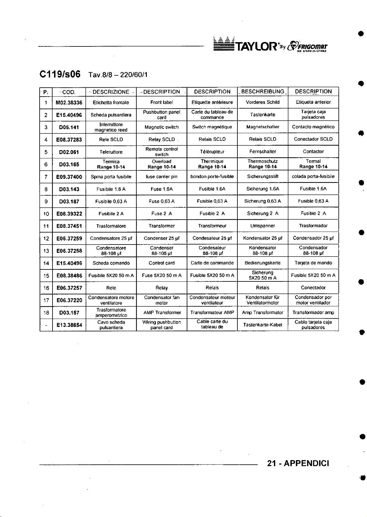
Page 100
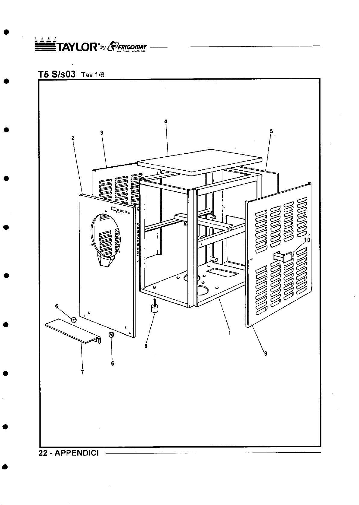
 Loading...