

Frigobox HKEB-HCNB-261-X, HKEB-HCNB-351-X Service Manual

SERVICESERVICE
MANUALMANUAL
SPLIT TYPE AIR CONDITIONERSPLIT TYPE AIR CONDITIONER
CONTENTS
1.PART NAMES AND FUNCTIONS...................
2.SPECIFICATION............................................
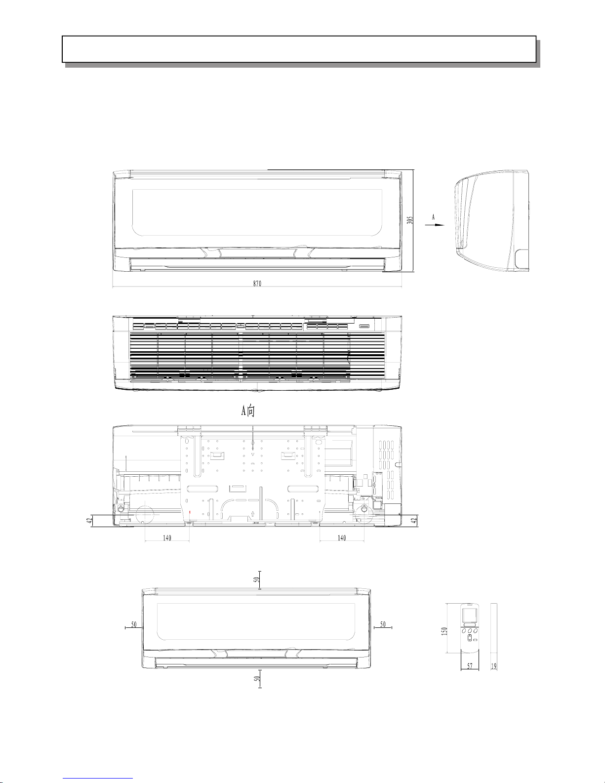
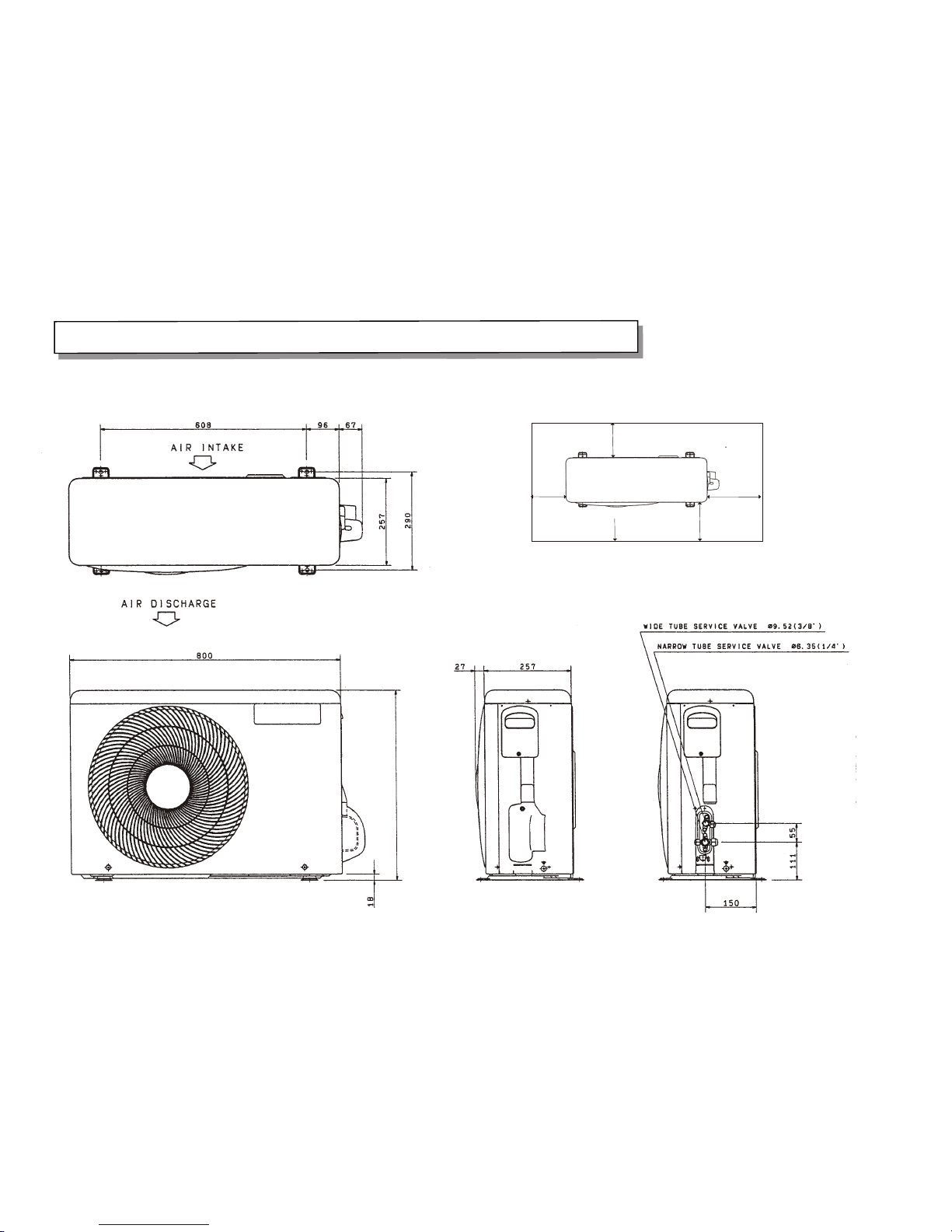
3.OUTLINES AND DIMENSIONS.......................
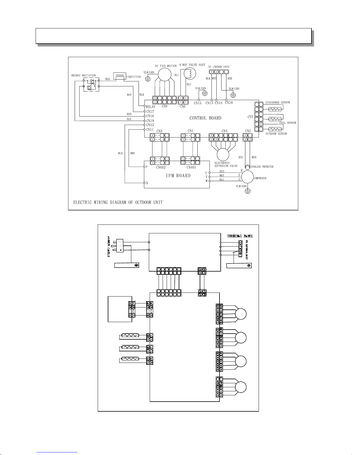
4.WIRING DIAGRAM.........................................
5.REFRIGERANT SYSTEM DIAGRAM...............
6.CONTROL MODE ................................
7.SERVICE FLOW CHART......................................
8.ELECTRIC .CONTROL.............................
9.SENSOR PARAMETER................................
10.DISASSEMBLY INSTRUCTIONS...................
11.PARTS LIST.................................................
HKEB-HCNB-261-X
HKEB-HCNB-351-X
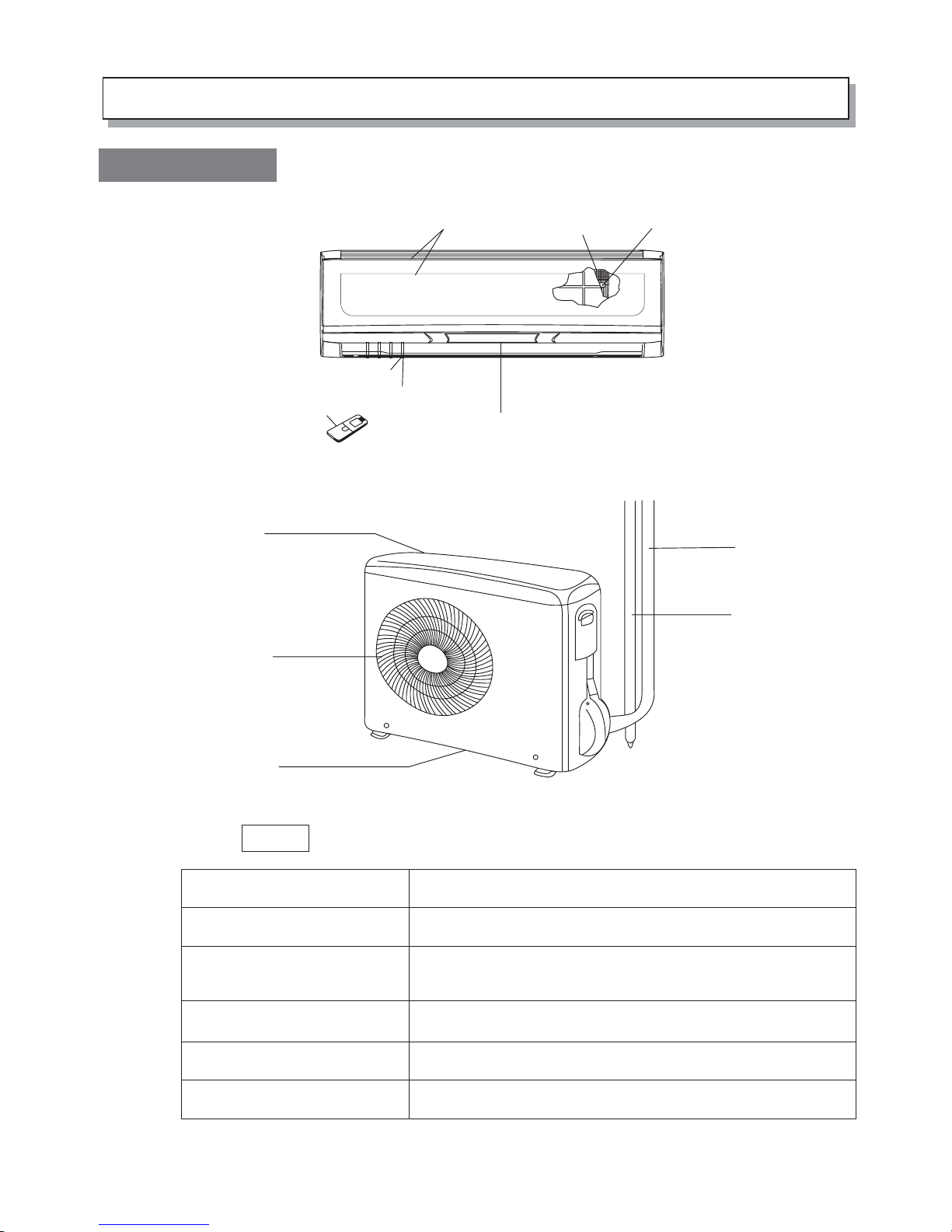
1. PART NAMES AND FUNCTIONS
1.Diagram of Structure
This air conditioner consists of an indoor unit and an outdoor unit. You can
control the air conditioner with the remote controller.
NOTE
Air Intake
Air Outlet
Remote Controller
Refrigerant Tubes
Outdoor(Condensing)Unit
Drain Hose
Air from the room is drawn into this section and passes
through air filters which remove dust.
Conditioned air is blown out of the air conditioner through
the air outlet.
The wireless remote controller controls power ON/OFF,
operation mode selection, temperature, fan speed, timer
setting, and air sweeping.
The indoor and outdoor units are connected by copper
tubes through which refrigerant gas flows.
The outdoor unit contains the compressor, fan motor, heat
exchanger coil, and other electrical components.
Moisture in the room condenses and drains off through this hose
Air filter
Air outlet
Impeller
Blue backlight LCD screen
Indoor sensor
Remote controller
Tubes and cable
Drain hose
Air inlet (rear and side)
Air outlet
Water drainage
Indoor unit
Outdoor unitt
Air intake
Appearance of the indoor may differ from some the picutres in the manual.
22、、SSPPEECCIIFFIICCAATTIIOONN
NOTE :Test conditions:Cooling : Indoor: DB27℃/ WB19℃ Heating: Indoor: DB20℃/ WB15℃
Outdoor DB35℃/ WB24℃ Outdoor DB7℃/ WB 6℃
Model HKEB -HCNB -261X
Function Cooling Heating
Power supply 220-230V~ 50Hz
Capacity k W 2.5 (0,39-3,2) 3.1 (0,40-3,53)
Dehumidification l /h 1.5
Capacity
Air flow m3/h 800 800
Power outlet A 16
Running current A 3.54/5.89 4.8/8.08
Power input k W 0.53 (0,3-1,05) 0.66 (0,3-1,25)
Auxiliary heater A(KW) --
Starting current A -Power factor % 90%
Electrical data
Compressor motor current A --
Coefficient of performance(C.O.P) 4.7/4.7
Model DA91A1F-22FD
Output W 750
Compressor
Winding resistance (at20℃)
Ω
1.10
Model SIC-37CV-F835-1 Indoor
fan motor Winding resistance (at20℃)
Ω -
Model DR-8938-504A-G Outdoor
fan motor Winding resistance (at20℃)
Ω -
Width mm 870
Height mm 225
Indoor unit
Depth mm 305
Width mm 800
Height mm 565
Dimensions
Outdoor unit
Depth mm 260
Indoor unit kg 11 Weight
Outdoor unit kg 34.5
Liquid pipe mm 6.35 Refrigerant
piping Gas pipe mm 9.52
Air direction 6
Indoor unit dB 46Sound leve l
(Hi)
Outdoor unit dB 53
Indoor unit rpm 1200 Fan speed
(Hi)
Outdoor unit rpm 760
Refrigerant filling capacity(R410A) kg 1.15
RT1(at25℃) k Ω 5
RT2(at25℃) k Ω 5
Special remarks
Sensor
RT 3(at0℃) k Ω 16.44

22、、SSPPEECCIIFFIICCAATTIIOONN
NOTE :Test conditions:Cooling : Indoor: DB27℃/ WB19℃ Heating: Indoor: DB20℃/ WB15℃
Outdoor DB35℃/ WB24℃ Outdoor DB7℃/ WB 6℃
Model HKEB - HCNB - 351 X
Function Cooling Heating
Power supply 220-230V~ 50Hz
Capacity k W 3.5 (0,39-3,98) 4.0 (0,4-4,49)
Dehumidification l /h 1.5
Capacity
Air flow m3/h 800 800
Power outlet A 16
Running current A 4.75/7.0 5.62/9.5
Power input k W 0.98 (0,3-1,3) 0.94 (0,3-1,6)
Auxiliary heater A(KW) --
Starting current A -Power factor % 90
Electrical data
Compressor motor current A --
Coefficient of performance(C.O.P) 3.57/4.26
Model DA91A1F-22FD
Output W 750
Compressor
Winding resistance (at20℃)
Ω
1.10
Model SIC-37CV-F835-1 Indoor
fan motor Winding resistance (at20℃)
Ω -
Model DR-8938-504A-G Outdoor
fan motor Winding resistance (at20℃)
Ω -
Width mm 870
Height mm 225
Indoor unit
Depth mm 305
Width mm 800
Height mm 565
Dimensions
Outdoor unit
Depth mm 260
Indoor unit kg 11 Weight
Outdoor unit kg 34.5
Liquid pipe mm 6.35 Refrigerant
piping Gas pipe mm 9.52
Air direction 6
Indoor unit dB 46 Sound leve l
(Hi)
Outdoor unit dB 53
Indoor unit rpm Fan speed
(Hi)
Outdo or unit rpm
Refrigerant filling capacity(R410A) kg 1.15
RT1(at25℃) k Ω 5
RT2(at25℃) k Ω 5
Special remarks
Sensor
RT 3(at0℃) k Ω 16.44
5.REFRIGERANT SYSTEM DIAGRAM3.OUTLINES AND DIMENSIONS
HKEB - HCNB 261-351 X
>25cm
>5cm
>10cm
Outlet
>40cm
5.REFRIGERANT SYSTEM DIAGRAM
3.OUTLINES AND DIMENSIONS
567.5
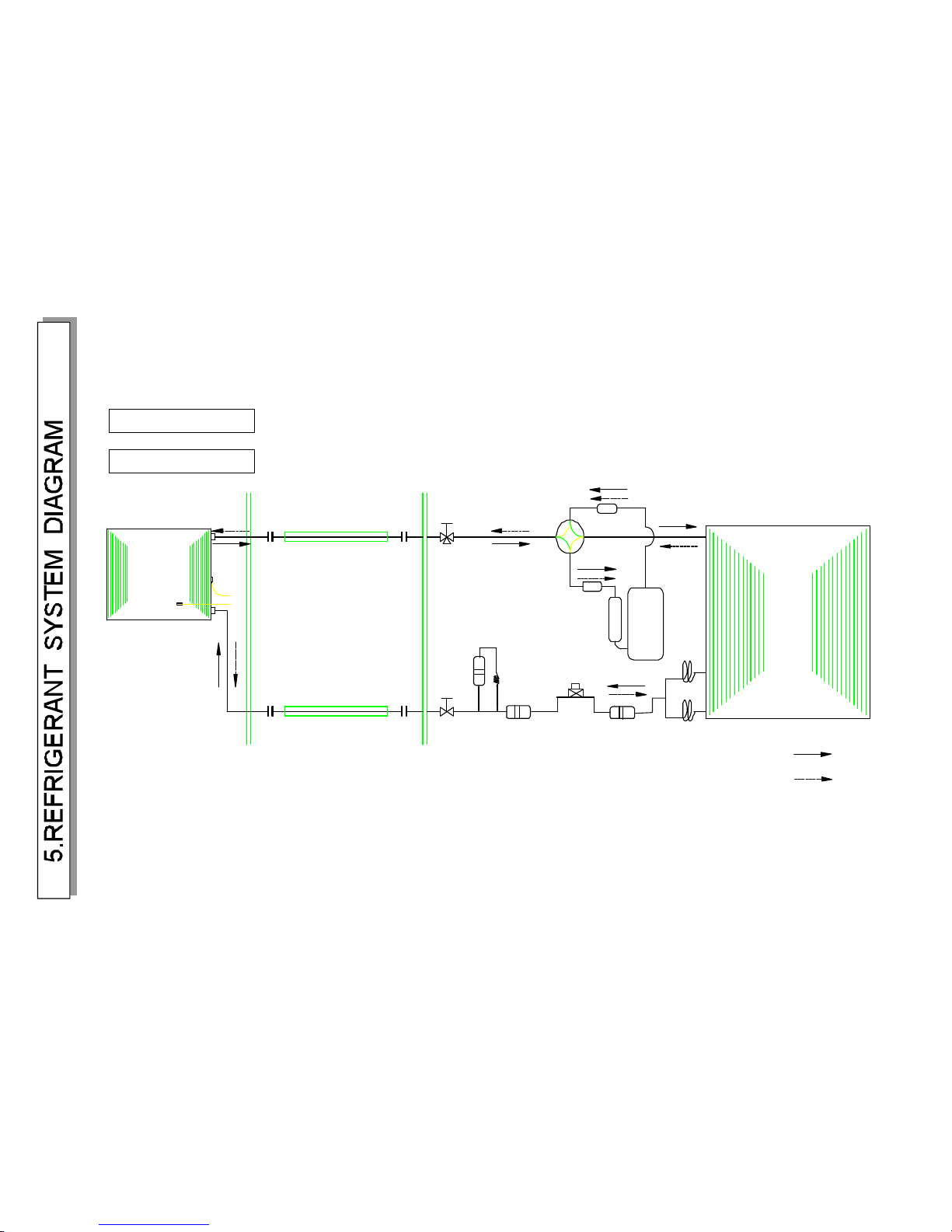
4.WIRINGDIAGRAM
ROOMSENSOR
COILSENSOR
CN101
FILTERBOARD
AIR OUTLETSENSOR
DISPLAY BOARD
CONTROLBOARD
21124334655
6
CN102
CN401
CN103
CN104
CN105
EVAPORATOR
CN701
CN106
21124334655
6
CN201
CN603
CN602
CN606
CN605
CN604
CN609
CN608
CN607
CN701
BRN
YLW/GRN
RED
YLW/GRN
WHT
BLK
YLW/GRN
BLU
EVAPORATOR
HORIZONTAL
FLAPMOTOR1
HORIZONTAL
FlAP MOTOR2
VERTICAL
FLAP MOTOR
DC FAN MOTOR
ELECTRIC WIRING DIAGRAM OF INDOOR UNIT
2
1
0
1
0
1
1
1
1
1
0
1
0
1
1
1
1
7
7
8
8
7
7
8
7
7
8
8
4
3
3
4
6
5
5
6
1
1
2
3
3
44
5
5
6
6
43
2 4
3
3
4
6
5
5
6
HKEB HCNB 261 X
(.52)φ9
(6.35)φ
Compressor
Rerigerant pipe
(With heat insulator)
Service valve
Indoortemperature
Heatexchanger
sensor
Flare connection
Refrigerant pipe
(With heat insulator)
Flare connection
Service valve
INDOORUNIT
Heatex changer
OUTDOORUNIT
Muffler
Desiccationfilter
4-way valve
Heating cycle
Cooling cycle
sensor
Indoorcoil
Muffler
Strainer
φ×51.500
Capillary tube
φ×51.500
Strainer
Electric expansion valve
HKEB HCNB 351 X
Limitations to refrigerant piping length and height difference
Maximum allowed refrigerant piping length (single line) and height difference
Models
HKEB-HCNB 261X
HKEB-HCNB 351X
Max. piping length
(m), single line: A
Piping diameter (mm)
Liquid side Gas side
9.52
6.35
9.52
6.35
Height Difference (m)
Indoor Unit above
Indoor unit below
15
15
7
7
7
7
Max. allowed
height difference:
7 metres
Max. refrigerant piping length (A): 15 metres
Indoor
Unit
Outdoor
Unit
Additional refrigerant charge (R410A refrigerant)
Models
HKEB-HCNB 261X
HKEB-HCNB 351X
Precharged amount
(g) up to 7 metres
1150
1150
Additional R410A charge according to piping length
7m
0g
0g
10m
75g
75g
15m
200g
200g
Calculation of the additional refrigerant charge: R410A g = [(A-7) meters x 25g/m]
Temperature range for regular operation:
Outdoor air temperature: • In Cooling mode: +16°C ~ +43°C
• In Heating mode: -15°C ~ +30°C
If this appliance is operated under temperature conditions out of the above specified temperature range, this may result
in malfunction and/or operation could stop due to intervention of built-in protective functions.
5.REFRIGERANT SYSTEM DIAGRAM
EVACUATION PROCEDURES
Connect the refrigerant pipes (both the liquid and gas
pipes) between the indoor and the outdoor units.
Remove the service port cap of the stop valve on the sid e o f the
outdoor unit gas pipe. (The sto p valv e w ill no t wor k in i ts initial
state fresh out of the factory (totally closed with cap on).
Connect the gage manifold valve and the vacuum pump to the service port o f the stop valve on the ga s pipe
side of the outdoor unit.
Run the vacuum pump for more than 15 minutes and at this time confirm that the pressure gage indicates
-0.1 Mpa (-76 cmHg).
Check the vacuum with the gage manifold valve, then close the gage manifold valve, and stop the
vacuum pump.
Leave it as is for one or two minutes .Make sure the pointer of the gage manifold valve remains in the.
same position.
Close
Open
Hexagonal
wrench
Stop valve
pipe
Connection
Gage manifold valve
Stop valve
Liquid pipe
Stop valve
Hexagonal
wrench
Gas pipe
Caps
Service port
Vacuum pump
Remove the gage manifold valve qu ickly from the ser vice port of the stop valve.
After refrigerant pipes are connected and evacuated, fully open all stop valves
on gas and liquid pipe sides.
Operating without fully opening lowers the performance and causes trouble.
£º
Pipe length
7m maximum
No gas charge is
needed.
Pipe length
exceeding 7m
Charge the prescribed
amount of gas.
Tighten the cap to the service port to obtain the initial status.
Retighten the cap.
Leak test
5.REFRIGERANT SYSTEM DIAGRAM
 Loading...