


SERVICESERVICE
MANUALMANUAL
SPLIT TYPE AIR CONDITIONERSPLIT TYPE AIR CONDITIONER
CONTENTS
1.PART NAMES AND FUNCTIONS...................
2.SPECIFICATION............................................
3.OUTLINES AND DIMENSIONS.......................
4.WIRING DIAGRAM.........................................
5.REFRIGERANT SYSTEM DIAGRAM...............
6.CONTROL MODE ................................
7.SERVICE FLOW CHART......................................
8.ELECTRIC .CONTROL.............................
9.SENSOR PARAMETER................................
10.DISASSEMBLY INSTRUCTIONS...................
11.PARTS LIST.................................................
HKEB-HCNB-261-X
HKEB-HCNB-351-X
1. PART NAMES AND FUNCTIONS
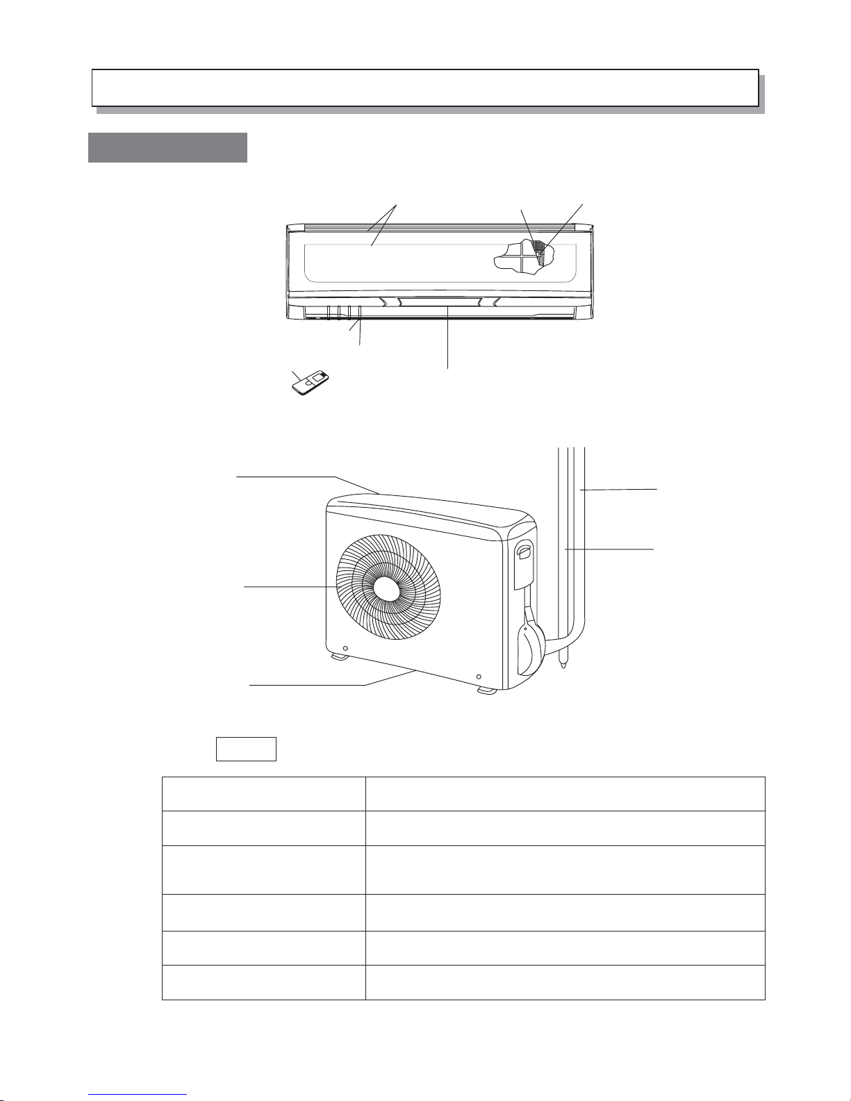
1.Diagram of Structure
This air conditioner consists of an indoor unit and an outdoor unit. You can
control the air conditioner with the remote controller.
NOTE
Air Intake
Air Outlet
Remote Controller
Refrigerant Tubes
Outdoor(Condensing)Unit
Drain Hose
Air from the room is drawn into this section and passes
through air filters which remove dust.
Conditioned air is blown out of the air conditioner through
the air outlet.
The wireless remote controller controls power ON/OFF,
operation mode selection, temperature, fan speed, timer
setting, and air sweeping.
The indoor and outdoor units are connected by copper
tubes through which refrigerant gas flows.
The outdoor unit contains the compressor, fan motor, heat
exchanger coil, and other electrical components.
Moisture in the room condenses and drains off through this hose
Air filter
Air outlet
Impeller
Blue backlight LCD screen
Indoor sensor
Remote controller
Tubes and cable
Drain hose
Air inlet (rear and side)
Air outlet
Water drainage
Indoor unit
Outdoor unitt
Air intake
Appearance of the indoor may differ from some the picutres in the manual.
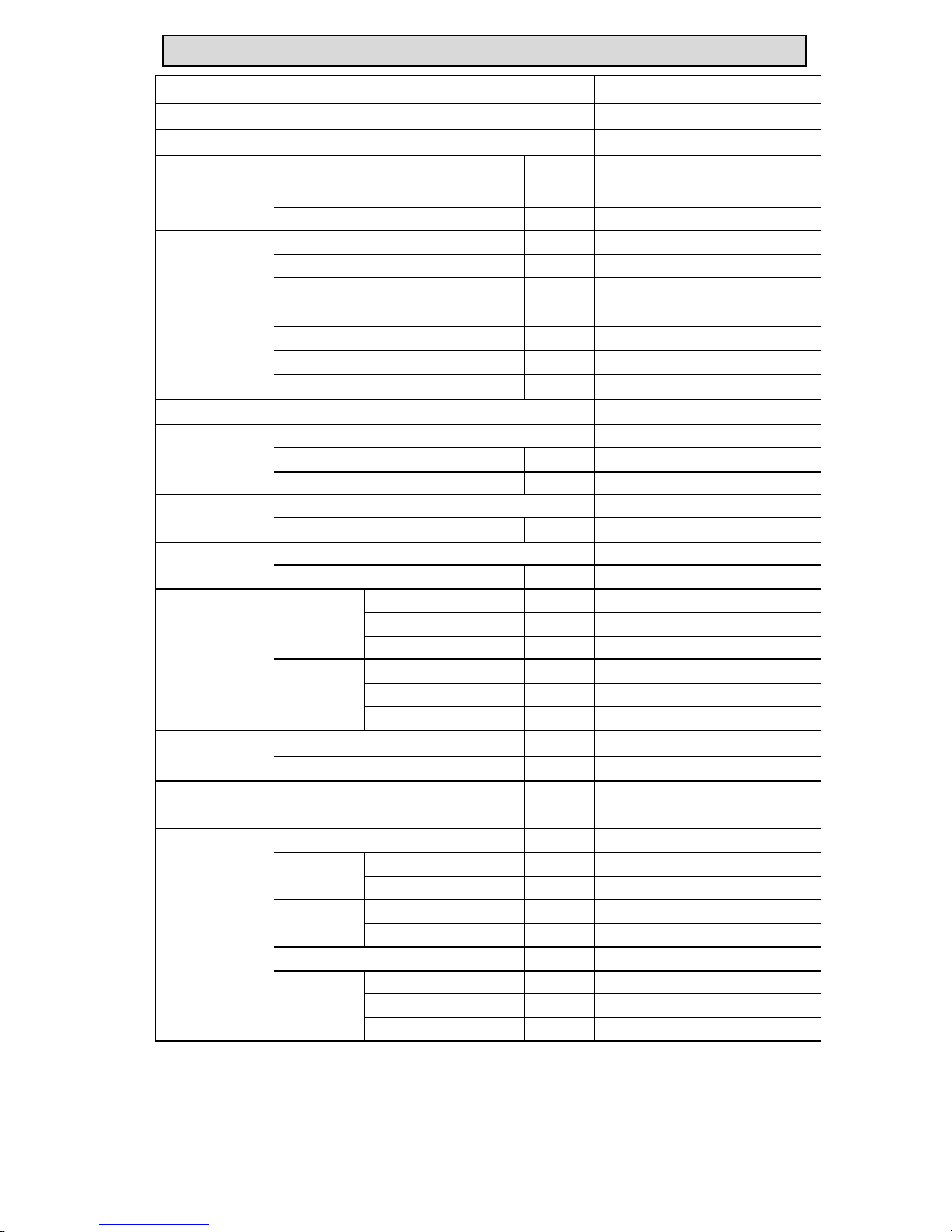
22、、SSPPEECCIIFFIICCAATTIIOONN
NOTE :Test conditions:Cooling : Indoor: DB27℃/ WB19℃ Heating: Indoor: DB20℃/ WB15℃
Outdoor DB35℃/ WB24℃ Outdoor DB7℃/ WB 6℃
Model HKEB -HCNB -261X
Function Cooling Heating
Power supply 220-230V~ 50Hz
Capacity k W 2.5 (0,39-3,2) 3.1 (0,40-3,53)
Dehumidification l /h 1.5
Capacity
Air flow m3/h 800 800
Power outlet A 16
Running current A 3.54/5.89 4.8/8.08
Power input k W 0.53 (0,3-1,05) 0.66 (0,3-1,25)
Auxiliary heater A(KW) --
Starting current A -Power factor % 90%
Electrical data
Compressor motor current A --
Coefficient of performance(C.O.P) 4.7/4.7
Model DA91A1F-22FD
Output W 750
Compressor
Winding resistance (at20℃)
Ω
1.10
Model SIC-37CV-F835-1 Indoor
fan motor Winding resistance (at20℃)
Ω -
Model DR-8938-504A-G Outdoor
fan motor Winding resistance (at20℃)
Ω -
Width mm 870
Height mm 225
Indoor unit
Depth mm 305
Width mm 800
Height mm 565
Dimensions
Outdoor unit
Depth mm 260
Indoor unit kg 11 Weight
Outdoor unit kg 34.5
Liquid pipe mm 6.35 Refrigerant
piping Gas pipe mm 9.52
Air direction 6
Indoor unit dB 46Sound leve l
(Hi)
Outdoor unit dB 53
Indoor unit rpm 1200 Fan speed
(Hi)
Outdoor unit rpm 760
Refrigerant filling capacity(R410A) kg 1.15
RT1(at25℃) k Ω 5
RT2(at25℃) k Ω 5
Special remarks
Sensor
RT 3(at0℃) k Ω 16.44

22、、SSPPEECCIIFFIICCAATTIIOONN
NOTE :Test conditions:Cooling : Indoor: DB27℃/ WB19℃ Heating: Indoor: DB20℃/ WB15℃
Outdoor DB35℃/ WB24℃ Outdoor DB7℃/ WB 6℃
Model HKEB - HCNB - 351 X
Function Cooling Heating
Power supply 220-230V~ 50Hz
Capacity k W 3.5 (0,39-3,98) 4.0 (0,4-4,49)
Dehumidification l /h 1.5
Capacity
Air flow m3/h 800 800
Power outlet A 16
Running current A 4.75/7.0 5.62/9.5
Power input k W 0.98 (0,3-1,3) 0.94 (0,3-1,6)
Auxiliary heater A(KW) --
Starting current A -Power factor % 90
Electrical data
Compressor motor current A --
Coefficient of performance(C.O.P) 3.57/4.26
Model DA91A1F-22FD
Output W 750
Compressor
Winding resistance (at20℃)
Ω
1.10
Model SIC-37CV-F835-1 Indoor
fan motor Winding resistance (at20℃)
Ω -
Model DR-8938-504A-G Outdoor
fan motor Winding resistance (at20℃)
Ω -
Width mm 870
Height mm 225
Indoor unit
Depth mm 305
Width mm 800
Height mm 565
Dimensions
Outdoor unit
Depth mm 260
Indoor unit kg 11 Weight
Outdoor unit kg 34.5
Liquid pipe mm 6.35 Refrigerant
piping Gas pipe mm 9.52
Air direction 6
Indoor unit dB 46 Sound leve l
(Hi)
Outdoor unit dB 53
Indoor unit rpm Fan speed
(Hi)
Outdo or unit rpm
Refrigerant filling capacity(R410A) kg 1.15
RT1(at25℃) k Ω 5
RT2(at25℃) k Ω 5
Special remarks
Sensor
RT 3(at0℃) k Ω 16.44
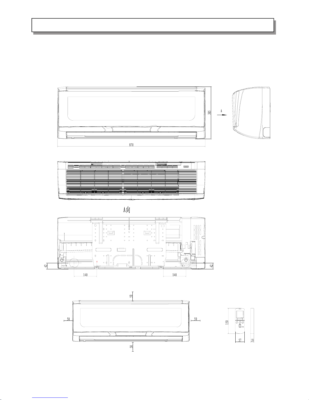
5.REFRIGERANT SYSTEM DIAGRAM3.OUTLINES AND DIMENSIONS
HKEB - HCNB 261-351 X
>25cm
>5cm
>10cm
Outlet
>40cm
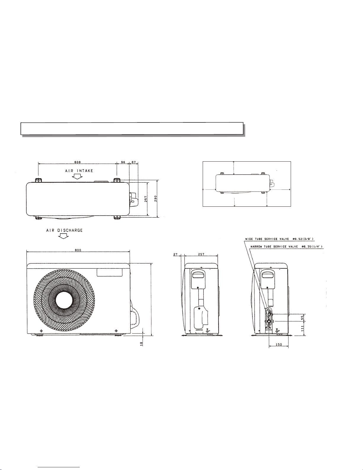
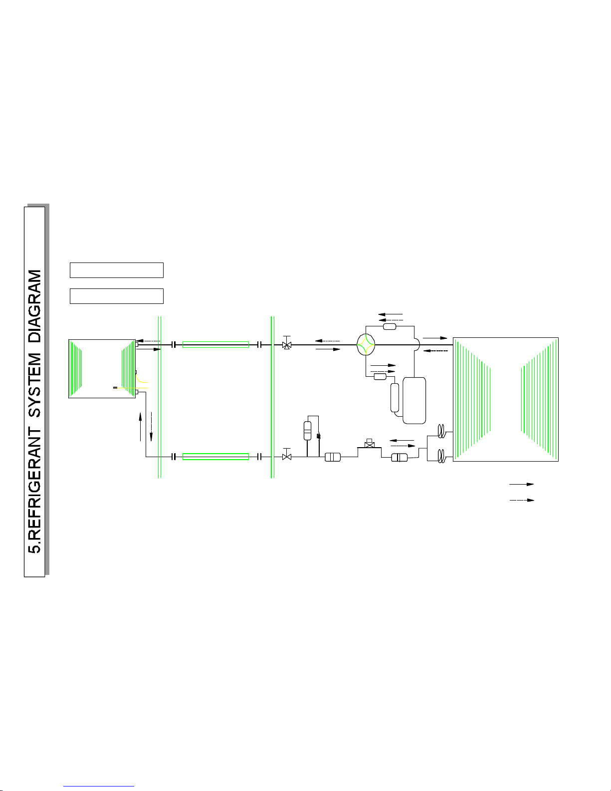
5.REFRIGERANT SYSTEM DIAGRAM
3.OUTLINES AND DIMENSIONS
567.5
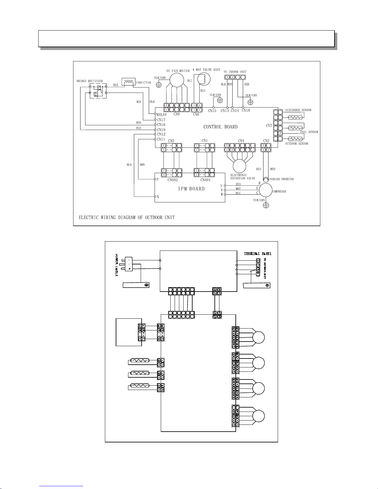
4.WIRINGDIAGRAM
ROOMSENSOR
COILSENSOR
CN101
FILTERBOARD
AIR OUTLETSENSOR
DISPLAY BOARD
CONTROLBOARD
21124334655
6
CN102
CN401
CN103
CN104
CN105
EVAPORATOR
CN701
CN106
21124334655
6
CN201
CN603
CN602
CN606
CN605
CN604
CN609
CN608
CN607
CN701
BRN
YLW/GRN
RED
YLW/GRN
WHT
BLK
YLW/GRN
BLU
EVAPORATOR
HORIZONTAL
FLAPMOTOR1
HORIZONTAL
FlAP MOTOR2
VERTICAL
FLAP MOTOR
DC FAN MOTOR
ELECTRIC WIRING DIAGRAM OF INDOOR UNIT
2
1
0
1
0
1
1
1
1
1
0
1
0
1
1
1
1
7
7
8
8
7
7
8
7
7
8
8
4
3
3
4
6
5
5
6
1
1
2
3
3
44
5
5
6
6
43
2 4
3
3
4
6
5
5
6
HKEB HCNB 261 X
(.52)φ9
(6.35)φ
Compressor
Rerigerant pipe
(With heat insulator)
Service valve
Indoortemperature
Heatexchanger
sensor
Flare connection
Refrigerant pipe
(With heat insulator)
Flare connection
Service valve
INDOORUNIT
Heatex changer
OUTDOORUNIT
Muffler
Desiccationfilter
4-way valve
Heating cycle
Cooling cycle
sensor
Indoorcoil
Muffler
Strainer
φ×51.500
Capillary tube
φ×51.500
Strainer
Electric expansion valve
HKEB HCNB 351 X
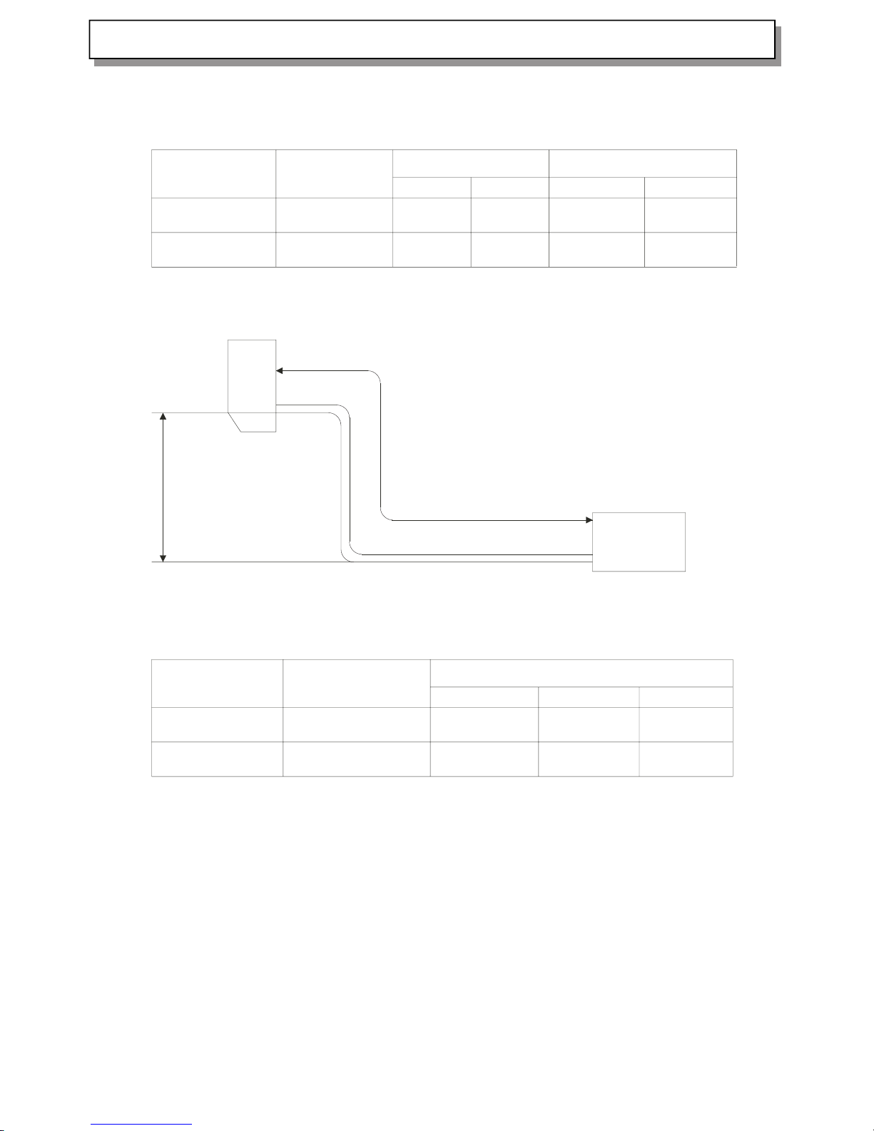
Limitations to refrigerant piping length and height difference
Maximum allowed refrigerant piping length (single line) and height difference
Models
HKEB-HCNB 261X
HKEB-HCNB 351X
Max. piping length
(m), single line: A
Piping diameter (mm)
Liquid side Gas side
9.52
6.35
9.52
6.35
Height Difference (m)
Indoor Unit above
Indoor unit below
15
15
7
7
7
7
Max. allowed
height difference:
7 metres
Max. refrigerant piping length (A): 15 metres
Indoor
Unit
Outdoor
Unit
Additional refrigerant charge (R410A refrigerant)
Models
HKEB-HCNB 261X
HKEB-HCNB 351X
Precharged amount
(g) up to 7 metres
1150
1150
Additional R410A charge according to piping length
7m
0g
0g
10m
75g
75g
15m
200g
200g
Calculation of the additional refrigerant charge: R410A g = [(A-7) meters x 25g/m]
Temperature range for regular operation:
Outdoor air temperature: • In Cooling mode: +16°C ~ +43°C
• In Heating mode: -15°C ~ +30°C
If this appliance is operated under temperature conditions out of the above specified temperature range, this may result
in malfunction and/or operation could stop due to intervention of built-in protective functions.
5.REFRIGERANT SYSTEM DIAGRAM
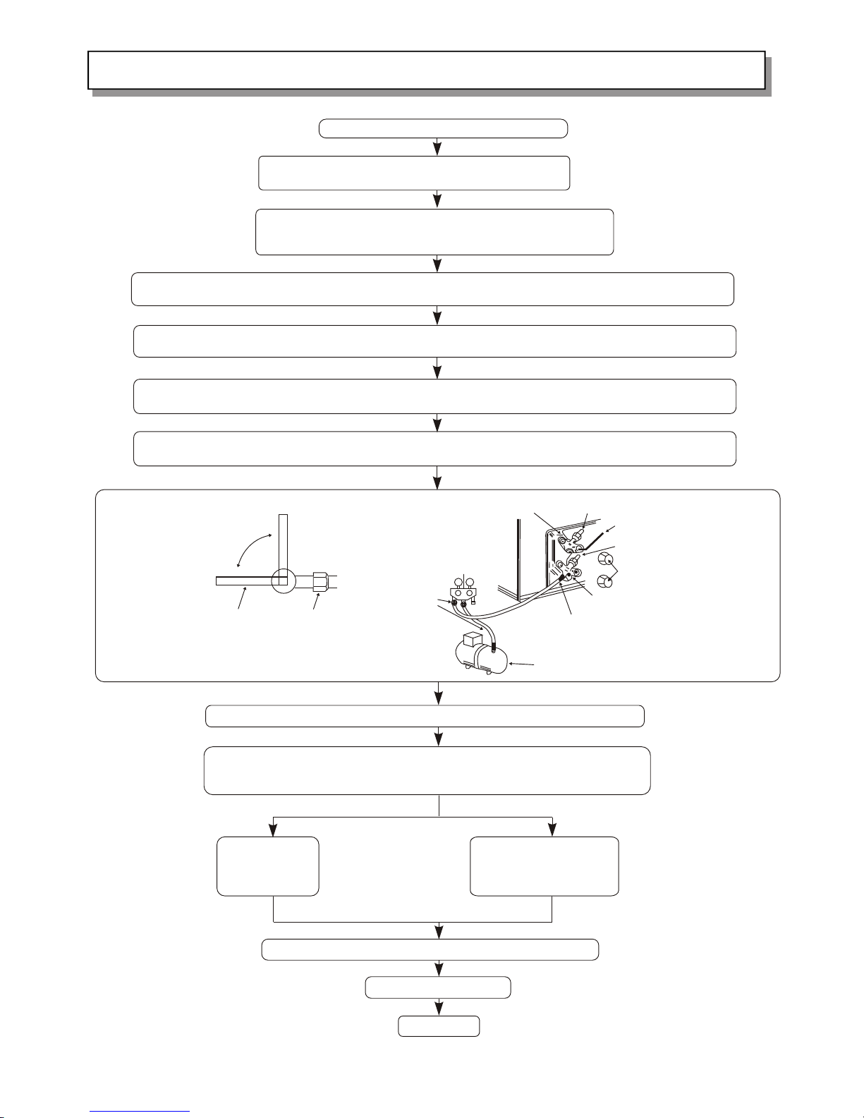
EVACUATION PROCEDURES
Connect the refrigerant pipes (both the liquid and gas
pipes) between the indoor and the outdoor units.
Remove the service port cap of the stop valve on the sid e o f the
outdoor unit gas pipe. (The sto p valv e w ill no t wor k in i ts initial
state fresh out of the factory (totally closed with cap on).
Connect the gage manifold valve and the vacuum pump to the service port o f the stop valve on the ga s pipe
side of the outdoor unit.
Run the vacuum pump for more than 15 minutes and at this time confirm that the pressure gage indicates
-0.1 Mpa (-76 cmHg).
Check the vacuum with the gage manifold valve, then close the gage manifold valve, and stop the
vacuum pump.
Leave it as is for one or two minutes .Make sure the pointer of the gage manifold valve remains in the.
same position.
Close
Open
Hexagonal
wrench
Stop valve
pipe
Connection
Gage manifold valve
Stop valve
Liquid pipe
Stop valve
Hexagonal
wrench
Gas pipe
Caps
Service port
Vacuum pump
Remove the gage manifold valve qu ickly from the ser vice port of the stop valve.
After refrigerant pipes are connected and evacuated, fully open all stop valves
on gas and liquid pipe sides.
Operating without fully opening lowers the performance and causes trouble.
£º
Pipe length
7m maximum
No gas charge is
needed.
Pipe length
exceeding 7m
Charge the prescribed
amount of gas.
Tighten the cap to the service port to obtain the initial status.
Retighten the cap.
Leak test
5.REFRIGERANT SYSTEM DIAGRAM

6.CONTROL MODE
1.Functional features
1.1 The compressor’ s motor system is fitted with DC brushless sensor without position, with
reliable and efficient performance;
1.2 The indoor and outdoor air supply motor is of built-in DC brushless type.
1.3 Throttle control by electronic expansion valve.
2 Main controlling functions
2.1 Controlling functions of the remote controller (see operation and installation manual)
2.2 Display icons of the indoor unit
Indicating lights
“ Simultaneous Operation Power Limitation” indicator: When the “ simultaneous
operation power limitation” function is started, this light goes on.
“ Timing” indicator: It goes on when “ timing” is selected.
“ Sleep” indicator: It goes on when “ sleep” is selected.
“ Night” indicator: No available for this unit.
Room temperature display
Fre
1-30(Hz)S1
31-50(Hz)S1S2
51-70(Hz)S1S2S3
71-90(Hz)S1S2S3S4
91(Hz) S1S2S3S4S5。
Room temperature is displayed in the “House”: The actually measured temperature of the unit
body or the remote controller is displayed.
Outdoor temperature display:
The outdoor temperature is displayed when detected by the outdoor unit. Otherwise, there is no
display.
Working mode display
During operation, such information as cooling, heating, dehumidifying is displayed. When the air
conditioner works in the Automatic Mode, the Auto icon, as well as the cooling/heating
information is displayed.
Fan speed display
The three blades of high, medium and low speeds are shown at the same time. “A” is displayed
when Auto Speed is selected.
Left and right swinging display
S1 S2 S3 S4 S5

6.CONTROL MODE
Surrounding air: K0, K1, K2, K4, K5
Directional air: Left K0, K1, K2, K3
Directional air: Right K0, K3, K4, K5
Directional air: Center K0, K2, K3, K4
Swinging air: K0K1, K0K2, K0K3 respectively according to the actual working status
Error message
Press the Emergency button for over 5 seconds when the power is on, the air conditioner will give
out alarm as follows: indoor unit trouble at the indoor temperature reading area and outdoor unit
trouble at the outdoor temperature area; the message is blinking at a frequency of 1Hz.
3.Temporary switch
3.1 If the remote controller is missing, press the temporary switch and the system starts in the
automatic mode, press the switch again to stop the system. Automatic mode follows:
A indoor temperature> 26℃ cooling mode temperature setting 26℃
B indoor temperature> 23℃ heating mode temperature setting 26℃
C 23℃≤indoor temperature≥26℃ fan mode
Indoor fan speed is automatic in automatic mode.
3.2 Hold down the temporary switch for 5 seconds or longer and the system is forced to run in the
cooling mode regardless of indoor temperature.
3.3. How to start the outdoor unit without the indoor unit
Short-circuit the two CN404 terminals on the IPM board of the outdoor unit, and switch on
the power, the air conditioner will start heating operation, and the outdoor fan is working; then
open the short circuit, the air conditioner will start cooling operation (the compressor starts 50
seconds later), and the fan is still working. Cut off the power, the outdoor unit will stop running.
4.Control mode
4.1 Automatic
4.1.1 When the air conditioner is switched on and the remote controller is set to Auto mode, the
air conditioner will select running modes automatically according to the difference
between the room temperature and the setting temperature.
4.1.2 The running mode will be set when the machine is first switched on. Once set, the
running mode cannot be changed within 30 minutes.
4.1.3 If the difference between the room temperature and the setting temperature exceeds 3
degrees, change the running mode immediately.
4.1.4 If the machine is turned off and restarted using the remote controller, the above conditions
are still good.
4.1.5 If the machine is powered off and restarted, the running mode must be re-selected.
4.1.6 The running frequency will be determined by the temperature difference.
4.2 Cooling
4.2.1 In the cooling mode, the preset temperature is determined by the remote controller. The
temperature range is 16℃—30℃.

6.CONTROL MODE
4.2.2 The compressor will start immediately when the machine is first powered on; it will take at
least 3min for the compressor to restart if the machine is restarted.
4.2.3 The fan speed changes in auto mode.
T
setting
- T
indoor
Fan speed T
setting
- T
indoor
Fan speed
1℃
Low
1℃
Low
2℃
Low
2℃
Mid
3℃
Mid
3℃
Mid
4℃
Mid
4℃
High
Temperature
difference
≥5℃
High
Temperature
difference
≥5℃
High
4.2.4 Compressor control
The running frequency of the compressor depends on the difference between the set
temperature and the detected room temperature. The larger the difference, the higher the frequency.
When the room temperature is lower than the set temperature, the compressor stops running
(provided the compressor keeps running for more than 5 minutes).
Min Max Rated Frequency.
15 100 42
4.3 Outdoor fan
One-speed, which runs simultaneously with the compressor.
4.4 Cooling overload
When T
external coil
≥70℃, the compressor stops. When T
external coil
≤50℃, the air conditioner
starts automatically in 3 minutes.
4.5 Anti-freezing function, the anti-freezing and frequency limiting functions of the evaporator
are effective:
When T
coil
> 10℃, the working frequency of the compressor is not limited;
When T
coil
< 7℃, the working frequency of the compressor begins dropping;
When T
internal coil
< -1℃ for 3 minutes, the indoor fan works normally after the compressor is
shut down.
When T
internal coil
≥7℃ and the compressor has stopped working for 3 minutes, the compressor
will restart running.
4.6 Current protection
is the normal working current value of E2ROM,I
max
is the ceiling current value of
E2ROM.

6.CONTROL MODE
I < IO -1.5A Without limitation.
I>I
O
+1.5A Frequency drops.
I≥I
max
Operation stops.
5. Dehumidification
5.1 In the dehumidification mode, the temperature is determined by the remote controller. The
temperature range is 16℃—30℃. The controller will determine the running mode according
to the indoor and outdoor temperature difference.
5.2 When the room temperature is 2℃ higher than the preset temperature, cooling run will be
5.3 T
set temperature
– T
room temperature
≥1℃ The compressor and the outdoor fan stop working,
and the indoor fan runs at a speed of 600 rpm.
6.Heating
6.1 When T
internal coil
≥ 38℃, the indoor fan works in accordance with the setting of
the remote controller.
T
setting
- T
indoor
Fan speed T
setting
- T
indoor
Fan speed
1℃
Low
1℃
Low
2℃
Mid
2℃
Low
3℃
Mid
3℃
Mid
4℃
Mid
4℃
Mid
5℃
High
5℃
Mid
Temperature
difference
≥6℃
High
Temperature
difference
≥6℃
High
6.2 Current protection
IO is the normal working current value of E2ROM,I
max
is the ceiling current value
of E2ROM.
I < IO -1.5A Without limitation.
I>I
O
+1.5A Frequency drops.
I≥I
max
Operation stops.
6.3 Defrosting
6.3.1 The defrosting is done through changing the flow direction of refrigerant inside of the
four-way valve.
6.3.2 Defrosting conditions:
Continuous heating run for more than 30min
During single machine operation, T
outdoor
– T
outdoor coil
≥ 12℃ and lasts 8minutes
6.3.3 Defrosting process:
Compressor and outdoor fan motor off → four-way valve off → compressor on →
defrosting conditions met → compressor off → four-way valve on → compressor on →
outdoor fan on → end
6.3.4 Overhot protection for the indoor heat exchanger

6.CONTROL MODE
When the temperature of the indoor coil≥78℃, the compressor will stop;
When the temperature≥63℃, the outdoor flow speed will turn to the low speed, and the
compressor runs at the descending frequency;
When the temperature<58℃, the compressor will prohibit the frequency from rising.
7 . Air cleaning
The outdoor unit doesn’ t work in this mode, and the indoor fan runs in cooling mode.
8.Protection
8.1 Abnormal sensor: when the sensor is short circuited or cut off, the compressor will stop, and
the trouble code will be displayed.
8.2. IPM error
In the case of IPM abnormalities, e.g. overheat (100℃), overcurrent (17A), or low driving
voltage (below 12V), both the compressor and the outdoor fan stop running, and the
corresponding error code is displayed.
8.3 Temperature protection for the compressor exhaust
When the compressor exhaust temperature <93℃, the compressor runs at the ascending
frequency;
When the temperature ≥93℃, and <115 ℃the compressor runs at the limit to the frequency
ascending;
When the temperature >115 ℃, the compressor stops.
8.4 Abnormal power supply voltage protection
When the supply voltage is above 260V or below 150V, the compressor stops, and the trouble
code is displayed.
8.5 No load protection
Measure the total current. When the current in the outdoor unit is lower than 0.15A, the
compressor will stop operation and no load protection error is displayed.
8.6 . Economical running
During economical run (this function is set on the remote controller), the working current will be
limited (to 60% of the max working current).
9 Automatic control of the electronic expansion valve
9.1 Power-on reset
Upon power-on reset, the expansion valve shuts off for 600 seconds first, and then opens to
a degree fit for the frequency.
9.2 The expansion valve regulates according to the outlet air temperature of the compressor.
Compressor rotor position signal not available
There is an LED indicator on the IPM board of the outdoor unit. During operation of the
compressor, the LED blinks to indicate frequency restriction conditions of the compressor.

6.CONTROL MODE
Content of trouble Indoor display code
Indoor sensor trouble
1
Evaporator sensor trouble
2
Evaporator freezing
3
Over hot of indoor heat exchanger
4
Communication trouble
5
Over current of compressor 7
Fan motor trouble
8
Indoor EEPROM 13
Outdoor sensor trouble 21
OUTDOOR
Outdoor sensor trouble 1
Outdoor coil sensor trouble 2
Discharge sensor 3
Compressor position 4
Communication trouble 5
Over current of whole system 6
No load 7
Abnormal power voltage 8
Compressor start-up failure 9
Higher outdoor exchange tempreture 10
Defrosting 11
IPM trouble 12
Data failure of outdoor E2PROM 13
Outdoor Fan 15
1. Normal operation, no frequency restriction.
2. Power voltage restriction.
3. Condenser temperature restriction.
4. Total current restriction.
5. Outlet air temperature restriction.
6. Indoor heat exchange temperature restriction for cooling operation.
7. Indoor fan speed restriction.
8 AD interface frequency conversion restriction.

Switch on the power
supply
Yes
Check the
result
Display board
prolem
Yes
No
Indoor control
board Is faulty
replace it
Check all wires
are connected
correctly
Start up self-test
function
Replace the battery
press RESET
botton ,retry remote
operation and
replace remote
Yes
Display board
problem
No
Yes
Check operation
Is the fuse
blown?
Yes
Check and find short
circuit or open circuit
among other components such
as fan motor?
Indoor control board
faulty
Error code 1
Indoor temperature
sensor trouble
Error code 2
Indoor coil
sensor trouble
Does LCD screen
display Normally?
Are the
wires
poorly
connected?
Does it receive
the remote
control signal?
Is the remote
controller in
good condition ?
After replacing
the display
board,Is there
still trouble?
Replace the
indoor board,Is
there still
trouble?
Is indoor
control board
short
circuit?
After replacing
the display
board,Is there
still trouble?
No
Yes
Yes
Yes
Yes
No
No
No
Measure
resistance
between
CN607 ①
and②
Measure
resistance
between
CN608 ①
and②
Does the
resistances of
thermistor have
the
characteristics on
page 31
Replace the
thermistor
Connect CN607 and
CN608、CN609.
Turn ON the power
supply and press
the EMERGENCY
OPERATION SWITCH
Replace the
indoor board
Ok *1
Does the
unit
operate 10
minutes or
more?
*1 Defective contact of the connector is considered
Yes
Yes
No
No
No
No
No
7.SERVICE FLOW CHART
Error code 7
Indoor air outlet
sensor trouble
Measure
resistance
between
CN609 ①
and②

Occur by chance
Error code 3
Indoor heat exchanger
is iced up
No
Indoor coil sensor
faulty,replace and
check operation
Yes
Switch to heat operation to defrost the heat
exchange coil,change back to cooling and
check operation
Check operation
Indoor control
board faulty ,
replace it
Normal
protection
No
Yes
Occur by chanceYes
Error code 4
indoor heat exchanger
is over loaded
Indoor coil sensor
faulty,replace and
check operation
Yes
Switch off the power,start up the
air conditoner in 10 minutes
Outdoor control
board
faulty,replace it
Yes
No
Indoor control
board faulty
replace it
No
Normal
protection
No
Yes
Switch off the power,replace the
outdoor control board and then
start up the air conditoner.
Swich off the power,replace the
outdoor control board and then
start up the air conditoner.
Is indoor heat
exchanger iced up?
Is compressor
still running?
Is indoor heat
exchanger
freezing up again?
Is the system
in good
condition?
Is compressor
still
running?
Is indoor heat
exchanger very
hot?
Is the system
in good
condition?
Is the system
in good
condition?
Error code 8
indoor fan motor trouble
No
Yes
Indoor control board
faulty and replace it
Set the air conditioner
operate in fan mode
Yes
No
No
Occor by chanceYes
Repair the indoor
fan motor
Does voltage repeat 0V DC
and 15V DC?
Is indoor fan
motor
running?
Insert screwdriver into to
rotate indoor fan motor
slowly for 1 revolution or
over,and measure voltage
NO.6(+) and NO.3(-) on CN701.
Does fan motor
stop with the
remote
controller
Does the socket CN701 of
indoor control board have
power input(DC 310V AND DC
15V)
Check if filters
are clean?
Ckeck if liquid
line strainer is
blocked?
If dirdy,wash
filters
No
Yes
Yes
If blocked,replace
the strainer
No
Check operation
7.SERVICE FLOW CHART
No
Yes
No

Error code 5
communication
problem
Connect the indoor
and outdoor unit
again according to
the wiring diagram
Yes
Yes
Replace the outdoor
control board and
start up again
Ourdoor control
board trouble
Yes
No
Indoor control
board fault,
replace it
No
No
There is a short circuit
behind the startup
resistor
The IPM.control
and wave filter
board Is faulty
or short
circuited
No
No
Yes Yes Replace it
No
No
No
Indoor FILTER board
faulty replace it
Yes
Connection wire
fault,tighten and
check
Yes
Connection wire
fault,tighten and
check
Connection wire
fault,tighten and
check
Yes
Connection wire
problem
Repair wiring as
required
Replace the
faulty unit
Yes
faulty electrical
connection
replace the
faulty
components
Yes
Outdoor control board
faulty replace it
Yes
Replace IPM board
and fuse
No
Check operation
Yes
No
Display board fault,
replace it
Yes
Normal protection and
replace fuse
No
Is the voltage
input of startup
resistor correct?
Is there power
output of indoor
unit main
relay(RL101)?
Is there 240V AC
between 1 and 2 on the
indoor terminal
block
Is there 240V AC
between 1 and 2 on
the outdoor terminal
block
Is the fuse in
control box
(20A) blown?
The startup
resistor Is
overhot?
Does the power
indicator (LED)of
outdoor control
board light up?
Are all the lead
wires connected
between indoor and
outdoor unit?
Is the system
in good
condition?
The control system of outdoor
unit has short circuit
trouble,check the connection
wire,wave filter board,outdoor
control board,IPM,rectifier and
electrolytic capacitor
Is outdoor
control board
short circuited?
Is IPM board short
circuited?
Check indoor and outdoor
interconnecting wiring for
short circuit
Is the system
in good
condition?
Is the
Fuse3(3.15A)
fuse of blown?
Is the
Fuse1(20A) fuse
of blown?
No
No
Yes
No
7.SERVICE FLOW CHART
Yes
Rectifier faulty
replace it
Yes
Replace the
faulty board
Does the
rectifier have
alternating
current input?
Is the reactor
and wave filter
board open
circuit?
No
Is the
resistor
TH101
correct?
Replace the
resistor
NO
NO

Error code outdoor 3
compressor over heat
protection
No
Outdoor control board
faulty , replace it
Replace it
No
Yes
Normal
protection
Yes
Yes
Replace
discharge
sensor
No
Error code outdoor 6
over current protection
No
Outdoor
control board
fault
Yes
Normal
protection
Yes Yes
No
Yes
Occur by chance
Error code 27
none load protection
No
replace outdoor
control board
IPM fault,
replace it
No
Yes
Yes
No
Yes
Compressor
faulty
Outdoor wave filter board
trouble and replace it
Check operation
No
Yes
Error code outdoor 8
voltage of power
supply Is abnormal
Outdoor control
board fault,
replace it
No
Normal protection
Error code outdoor
15
fan motor error
Switch off the power
supply and start up in
3 minutes
Is the over hot
switch of
compressor open
circuit?
I
s the resistance
of compressor
discharge sensor
correct?
Swich off and
start up
again,Is it ok?
Is the
operating
current beyond
Normal range?
Is the surface
of compressor
very hot?
Switch off and
start up
again,Is it
ok?
Replace the
outdoor IPM
control board,Is
it ok?
Replace the
outdoor control
board,Is it ok?
Is the voltage of power
supply Normal of AC
176-264V?
Is there DC 310
voltage input
between P-N on
IPM board
Is there voltage
output between IPM
board and U-V-W?
Is the compressor
running?
Replace compressor
Check operation
Yes
7.SERVICE FLOW CHART
No
Occor by chanceYes
Does fan
motor
run normal?
outdoor control board
faulty and replace it
Yes
No
Repair the outdoor
fan motor
Does voltage repeat
0V DC and 15V DC?
Insert screwdriver into to
rotate indoor fan motor
slowly for 1 revolution or
over,and measure voltage
NO.6(+) and NO.3(-) on CN9.
Does the socket CN9 of
outdoor control board have
power input(DC 310V AND DC
15V)
Yes
No
Replace
outdoor
EEPROM
EEPROM error
YES
NO

Error code outdoor10
condenser over load
No
Yes
Outdoor control board
faulty replace it
Yes
No
Normal
protection
Outdoor coil
sensor fault
Trouble code
outdoor3
EEPROM trouble
Outdoor control
fault, replace it
Error code outdoor12
IPM trouble
No
Yes
IPM fault and
replace it
Is the
IPM heat sink very
hot?
No
Yes
Normal protection
Assure good
ventilation
of outdoor
unit and good
contact
between IPM
and heat sink
Yes
No
Yes
Normal protection
No
Yes
No
Is the
IPM heat sink very
hot?
Yes
Yes
Yes
No No
Check operation
Replace the
outdoor control
board,Does this
fault disappear?
Replace the wave
filter
board,Does this
fault disappear?
IPM trouble
appear
frequently?
Start up the air
conditioner in 30
minutes,does it
work Normally?
IPM fault appears
frequently?
Is the resistance of
outdoor coil sensor
correct?
Does the trouble
disappear in 3
minutes ?
Is the outdoor
heat exchanger
really hot?
Trouble code
indoor13
EEPROM trouble
Indoor control board
fault , replace it
Replace
sensor
Check operation
Error code
outdoor 1
outdoor
temperature
sensor trouble
Error code
outdoor 2
outdoor coil
sensor trouble
Measure
resistance
between CN7
① and②
Measure
resistance
between CN7
③ and④
Does the
resistances of
thermistor have
the
characteristics on
page 31.
Replace the thermistor
Connect CN7.
Turn ON the power
supply and press
the EMERGENCY
OPERATION SWITCH
Replace the
outdoor board
Ok *1
Does the
unit operate
10 minutes
or more?
*1 Defective contact of the connector is considered
Yes
Yes
No
No
Yes
7.SERVICE FLOW CHART

Error code outdoor 4
compressor rotor
position test error
No
Yes
Outdoor IPM control
board faulty replace
it
NO
YES
Normal
pretection
EEPROM error
replace the outdoor
EEPROM,then start up
the ai-condioner and
test
Shut down the
air-conditioner and
start up after 5
minutes or
more,then test
Error code outdoor 9
compressor start up
error
No
Yes
Outdoor IPM control
board faulty replace
it
NO
YES
Normal
pretection
EEPROM error
replace the outdoor
EEPROM,then start up
the ai-condioner and
test
Shut down the
air-conditioner and
start up after 5
minutes or
more,then test
7.SERVICE FLOW CHART

DC310V
+V15+V15
SENSOR
SENSOR
SENSOR
+12V+12V
+5V+5V
Display board
Electrical outlet
Step motor
Step motor
7805 12V+7805 12V
7805 5V+7805 5V
220V From power board()220V From power board()
Step motor
+5V+ 5V
+12V+12V
+12V+12V
+12V+12V
FAN MOTOR CONTROL
Control
To power board()
Control
To power board(
SI
HKEB - HCNB 351 X
HKEB - HCNB 261 X
8.ELECTRIC CONTROL BOARD

220V Output
+12V+12V
220V Input
From power supply()
220V Input
From power supply()
+5V+5V
220 Output
SI
TO TERMINAL
SI
HKEB - HCNB 351 X
HKEB - HCNB 261 X
8.ELECTRIC CONTROL BOARD

220V INPUT
From terminal
board()
220V
INPUT
From terminal
board()
+5V
+15V
Electric expansion
valve control
Electric expansion
valve
control
4-way valve4-way valve
+12V
sensor
Fan motor controlFan motor control
DC+
DC-
+15V
CONTROL
SINGAL TO IPM()
CONTROL
SINGAL TO IPM()
AC OUTPUT
SI
DC+DC+
DC-DC-
TO I PM
TO I PM
INPUT
8.ELECTRIC CONTROL BOARD
HKEB - HCNB 351 X
HKEB - HCNB 261 X

HKEB - HCNB 351 X
HKEB - HCNB 261 X
8.ELECTRIC CONTROL BOARD
IPM BACK

T('c) R(K o) V (v) T('c) R(K o) V(v) T('c) R(Ko) V(v)
- 20 3 9.58 0.5307 9 1 0.1 1 .5878 3 8 3 .265 2.9504
- 19 3 7.58 0.5558 1 0 9 .684 1.6338 3 9 3 .151 2.9932
- 18 3 5.69 0.5818 1 1 9 .284 1.6805 4 0 3 .041 3.0358
- 17 3 3.91 0.6087 1 2 8 .903 1.7276 4 1 2 .936 3.0775
- 16 3 2.23 0.6363 1 3 8.54 1 .7749 4 2 2 .835 3.1188
- 15 3 0.65 0.6648 1 4 8 .194 1.8226 4 3 2 .739 3 .159
- 14 2 9.15 0.6942 1 5 7 .864 1.8704 4 4 2 .646 3 .199
- 13 2 7.74 0.7244 1 6 7 .549 1.9185 4 5 2 .556 3.2387
- 12 26 .4 0 .7556 1 7 7 .249 1.9667 4 6 2 .471 3.2771
- 11 2 5.14 0.7875 1 8 6 .962 2.0151 4 7 2 .388 3.3155
- 10 2 3.95 0.8202 1 9 6 .688 2.0636 4 8 2 .309 3.3528
- 9 2 2.82 0.8539 2 0 6 .427 2. 112 4 9 2 .233 3.3896
- 8 2 1.75 0.8885 2 1 6 .178 2.1603 5 0 2 .159 3.4262
- 7 2 0.74 0.9237 2 2 5 .939 2.2089 5 1 2 .089 3.4615
- 6 1 9.79 0.9596 2 3 5 .712 2. 257 5 2 2 .021 3.4965
- 5 1 8.88 0.9966 2 4 5 .494 2.3053 5 3 1 .956 3.5306
- 4 1 8.02 1.0343 2 5 5 .286 2.3533 5 4 1 .893 3.5644
- 3 17 .2 1 .0731 2 6 5 .086 2.4014 5 5 1 .832 3.5977
- 2 1 6.43 1.1122 2 7 4 .896 2.4489 5 6 1 .774 3.6299
- 1 15 .7 1.152 2 8 4 .714 2.4963 5 7 1 .718 3.6616
0 15 1 .1929 2 9 4 .539 2.5436 5 8 1 .664 3.6926
1 1 4.34 1.2342 3 0 4 .372 2.5904 5 9 1 .612 3.7231
2 1 3.71 1.2765 3 1 4 .212 2.6369 6 0 1 .562 3.7528
3 1 3.11 1.3195 3 2 4 .059 2. 683 6 1 1 .513 3.7824
4 1 2.55 1.3623 3 3 3 .912 2.7288 6 2 1 .467 3.8106
5 1 2.01 1.4063 3 4 3 .772 2.7738 6 3 1 .422 3.8386
6 11 .5 1 .4506 3 5 3 .637 2.8188 6 4 1 .379 3.8658
7 1 1.01 1.4959 3 6 3 .508 2.8631 6 5 1 .337 3.8927
8 1 0.55 1. 541 3 7 3 .384 2. 907
THE PARAMETER OF THE COIL AND INDOOR AND OUTDOOR SENSOR
9.SENSOR PARAMETER

9.SENSORPARAMETER
T ('C) R (O ) V ( v) T ( ' C ) R ( O ) V ( v) T('C) R (O ) V( v)
-10 313.4 0.3 31 44.74 1.545 71 9.659 3.372
-9 297.2 0.315 32 42.89 1.59 72 9.331 3.409
-8 281.9 0.331 33 41.13 1.636 73 9.016 3.446
-7 267.5 0.348 34 39.44 1.682 74 8.712 3.483
-6 253.9 0.365 35 37.84 1.729 75 8.421 3.519
-5 241.1 0.383 36 36.3 1.776 76 8.14 3.554
-4 229 0.402 37 34.84 1.823 77 7.869 3.588
-3 217.6 0.421 38 33.44 1.871 78 7.609 3.622
-2 206.8 0.441 39 32.11 1.919 79 7.359 3.655
-1 196.6 0.462 40 30.83 1.967 80 7.118 3.688
0 186.9 0.483 41 29.61 2.016 81 6.885 3.72
1 177.8 0.506 42 28.45 2.064 82 6.662 3.751
2 169.2 0.529 43 27.34 2.112 83 6.446 3.781
3 161 0.552 44 26.27 2.161 84 6.239 3.811
4 153.3 0.577 45 25.25 2.21 85 6.039 3.84
5 146 0.602 46 24.28 2.258 86 5.846 3.869
6 139 0.629 47 23.35 2.307 87 5.661 3.897
7 132.5 0.656 48 22.46 2.355 88 5.482 3.924
8 126.3 0.684 49 21.6 2.404 89 5.309 3.951
9 120.4 0.712 50 20.79 2.452 90 5.143 3.977
10 114.8 0.742 51 20.01 2.499 91 4.982 4.003
11 109.5 0.772 52 19.26 2.547 92 4.827 4.028
12 104.4 0.804 53 18.54 2.595 93 4.678 4.052
13 99.66 0.836 54 17.85 2.642 94 4.534 4.076
14 95.13 0.869 55 17.19 2.689 95 4.395 4.099
15 90.82 0.902 56 16.56 2.735 96 4.261 4.122
16 86.74 0.937 57 15.96 2.781 97 4.132 4.144
17 82.85 0.972 58 15.38 2.826 98 4.007 4.165
18 79.16 1.008 59 14.82 2.872 99 3.886 4.187
19 75.65 1.045 60 14.29 2.916 100 3.77 4.207
20 72.32 1.083 61 13.78 2.96 101 3.658 4.227
21 69.15 1.122 62 13.28 3.005 102 3.549 4.246
22 66.13 1.161 63 12.81 3.048 103 3.444 4.265
23 63.27 1.201 64 12.36 3.09 104 3.343 4.284
24 60.54 1.242 65 11.93 3.132 105 3.15 4.32
25 57.94 1.283 66 11.51 3.174 106 3.059 4.337
26 55.46 1.325 67 11.11 3.214 107 2.97 4.354
27 53.11 1.368 68 10.73 3.254 108 2.884 4.37
28 50.86 1.411 69 10.36 3.294 109 2.802 4.386
29 48.72 1.455 70 10 3.333 110 2.721 4.401
30 46.68 1.5
THEPARAMETEROFTHEDISCHARGESENSOR

10. DISASSEMBLY INSTRUCTIONS
1.Remove the grille
1)Take out the screw of the installation plate and remove
the installation plate.
2)Take out the screws of the mounting plate .
3)Hold the both sides of the front panel and drag it towards
oneself and remove it.
4)Take out the screws of the ornamengt grille and remove the
ornament grille.
5)Take away the air filters in the grille.
6)Open the screw cover ,then take out the screws of the
grille and remove the grille.
7) Remove the mounting plate.
HKEB 261 X
OPERATION PROCEDURE
PHOTOS
Screw
Installation Plate
Screw
Mounting Plate
Base Ass'y
Front Panel
Grille
Ornament Grille
Air Filter
Screw
Screw
Display Board
2.Remove the electrical control box
1)Take out the screw of the electrical cover and remove it.
2)Remove the indoor coil sensor from the sensor bracket.
3)Take out the screws of the electrical control box and
disconnect all the connectors on the printed circuit
board,then remove the electrical box.
Screw
Electrical Cover
Indoor Coil Sensor
Screw
Terminal Screw
Screw
HKEB 351 X

10. DISASSEMBLY INSTRUCTIONS
1)Remove the air outlet frame.
2) Take out the screws of the evaporator supportor and remove
the evaporator supportor.
3) Take out the screws of the motor cover and remove the motor
cover.
4) Take away the mounting plate and then remove the evaporator.
3.Remove the air outlet frame and the evaporator
1)Take out the screw of the rubber cover and remove the
rubber cover.
2)Remove the screw connecting the fan motor and the
cross-flow fan.
3)Remove the fan motor and the bearing ass'y.
4)Remove the cross-flow fan.
4. Remove the fan motor and the cross-flow fan
HKEB 261 X
Evaporator
Air Outlet Frame
Screws
Evaporator Supportor
Screws
Motor Cover
Mounting late
Cross-Flow Fan
Base Ass'y
Fan Motor
Fan Motor
Screws
Screw
Rubber Cover
Bearing Ass'y
HKEB 351 X

1.Remove the top panel and the front panel
1)Take out the screws of the top panel and remove the top
panel.
2)Take out the screws of the strengthen plate and remove it.
3) Take out the screws of the front panel and remove the panel.
2.Remove the electrical control box
1)Take out the screws of the valve cover and remove the
valve cover.
2)Take out the screws of the side cover and remove the cover.
3)Take out the screws of the electrical box cover and remove it.
4) Disconnect all the wires in the electrical control box and the
other parts.
4)Take out the screws of the electrical control box and remove
electrical control box.
OPERATION PROCEDURE
PHOTOS
10. DISASSEMBLY INSTRUCTIONS
HCNB 261 X - HCNB 351 X
Screw
Screw
Screw
Top Panel
Side Cover
Valve Cover
Front Panel
Fan Guard
Screw
Screw
Strengthen Plate
Screw
Screw
Screw
Screw
Screw
Screw
Electrical cover
Outside fan
Fan supportor
Electrical Box
Condenser Ass'y

1)Take out the screws of the back panel.
2)Remove the back panel.
3.Remove the back panel
1)Take out the special nut of the fan and remove the fan.
2)Take out the screws of the fan motor and remove the fan motor.
3)Take out the screws of the fan supporter and remove the
fan supporter.
4)Take out the screws of the partition plate and remove
the partition plate.
1)Check-up the condenser ass'y.
2)Check-up the compreesor ass'y.
3)Check-up the base ass'y.
5.Check-up the other parts of the outdoor units
Compreesor ass'y
Base ass'y
Condenser ass'y
Fan
Special nut
HCNB 261 X - HCNB 351 X
Fan Supportor
Seperator Plate
Screw
Screw
10. DISASSEMBLY INSTRUCTIONS
4.Remove the fan ,fan motor,fan supportor and the separate
plate.
 Loading...