


SERVICE MANUAL
Air Conditioners
CAUTION
READ THIS MANUAL CAREFULLY TO
DIAGNOSE TROUBLE CORRECTLY
BEFORE OFFERING SERVICE .
MODEL:
IMPORTANT INFORMATION
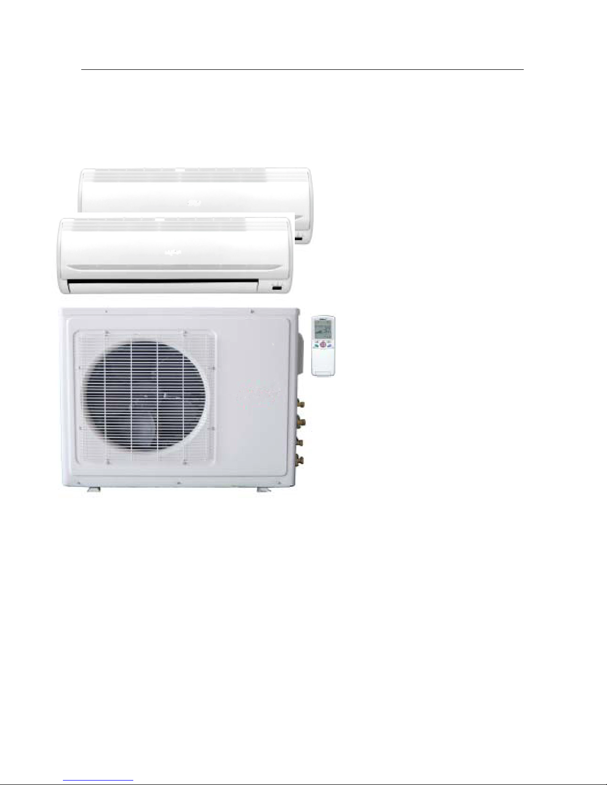
ƽҏFeatures
ƽҏComfortable: wide-angle airflow
ƽhealth air purifying
ƽquiet operation
ƽҏsuper energy efficient
ƽMain Specification
ƽCooling CapacityΚ 2600/3500/5300W
ƽRated Power/Current(cooling)Κ680/990/1600W/7.8A
ƽEER: 3.8/3.5/3.3W/W
ƽHeating CapacityΚ 3200/3800/6600W
ƽRated Power/Current(heating): 1185/1455/1930W/9.2A
ƽCOP: 2.7/2.6/3.4W/W
ƽAir Volume(Indoor): 500/550m
3
/h
ƽPower: 1PH 220-230V~ 50 Hz
MODEL: HKEL 261 XR + HKEL 351 XR

IMPORTANT INFORMATION
ƽҏFeatures
ƽҏComfortable: wide-angle airflow
ƽhealth air purifying
ƽquiet operation
ƽҏsuper energy efficient
ƽMain Specification
ƽCooling CapacityΚ 2600/5200W
ƽRated Power/Current(cooling)Κ680/1520W/7.5A
ƽEER: 3.8/3.29W/W
ƽHeating CapacityΚ 3200/6500W
ƽRated Power/Current(heating): 1185/1880W/8.8A
ƽCOP: 2.8/3.2W/W
ƽAir Volume(Indoor): 500m
3
/h
ƽPower: 1PH 220-230V~ 50 Hz
MODEL: HKEL 261 XR x 2


Before disposing an old air conditioner that
goes out of use, please make sure it's inoperative and safe. Unplug the air conditioner
in order to avoid the risk of child entrapment.
It must be noticed that air conditioner system
contains refrigerants, which require specialized waste disposal. The valuable materials
contained in an air conditioner can be recycled
.Contact your local waste disposal center for
proper disposal of an old air conditioner and
contact your local authority or your dealer if
you have any question. Please ensure that
the pipework of your air conditioner does not
get damagedprior to being picked up by the
relevant waste disposal center, and contribute
to environmental awareness by insisting on an
appropriate, anti-pollution method of disposal.
Cautions
Disposal of the old air conditioner
All the packaging materials employed in the
package of your new air conditioner may be
disposed without any danger to the
environment.
The cardboard box may be broken or cut into
smaller pieces and given to a waste paper
disposal service. The wrapping bag made of
polyethylene and the polyethylene foam pads
All these valuable materials may be taken to
a waste collecting center and used again after
adequate recycling.
Consult your local authorities for the name
and address of the waste materials collecting
centers and waste paper disposal services
nearest to your house.
Disposal of the packaging of your
new air conditioner
Before starting the air conditioner, read the
information given in the User's Guide carefully. The User's Guide contains very important observations relating to the assembly,
operation and maintenance of the air
conditioner.
The manufacturer does not accept responsibility for any damages that may arise due
to non-observation of the following
instruction.
Damaged air conditioners are not to be
put into operation. In case of doubt, consult
your supplier.
Use of the air conditioner is to be carried
out in strict compliance with the relative
instructions set forth in the User's Guide.
Installation shall be done by professional
people, don't install unit by yourself.
For the purpose of the safety,the air conditioner must be properly grounded in accordance with specifications.
Always remember to unplug the air
conditioner before openning inlet grill. Never
unplug your air conditioner by pulling on
the power cord. Always grip plug firmly and
pull straight out from the outlet.
All electrical repairs must be carried out
by qualified electricians. Inadequate repairs
may result in a major source of danger for
the user of the air conditioner.
Safety Instructions and Warnings
Do not damage any parts of the air
conditioner that carry refrigerant by piercing
or performating the air conditioner's tubes
with sharp or pointed items, crushing or
twisting any tubes, or scraping the coatings
off the surfaces. If the refrigerant spurts
out and gets into eyes, it may result in
serious eye injuries.
Do not obstruct or cover the ventilation
grille of the air conditoner.Do not put fingers
or any other things into the inlet/outlet and
swing louver.
Do not allow children to play with the air
conditioner.In no case should children be
allowed to sit on the outdoor unit.
The refrigerating circuit is leak-proof.
1.Applicable ambient temperature range:
Specifications
The machine is adaptive in following
situation
10 .The power plug and connecting cable
must have acquired the local attestation.
2. If the power supply cord is damaged, it
must be replaced by the manufacturer
or its service agent or a similar qualified
person.
3. If the fuse of indoor unit on PC board is
broken,please change it with the type of
T. 3.15A/ 250V. If the fuse of outdoor
unit is broken,change it with the type of
T.25A/250V
4. The wiring method should be in line with
the local wiring standard.
5. After installation, the power plug should
be easily reached.
6. The waste battery should be disposed
properly.
7. The appliance is not intended for use
by young children or infirm persons
without supervision.
8. Young children should be supervised
to ensure that they do not play with
the appliance.
9.Please employ the proper power plug,
which fit into the power supply cord.
Cautions
Cooling
Indoor
Maximum:D.B/W.B
Maximum:D.B/W.B
Maximum:D.B
Maximum:D.B
Maximum:D.B
Minimum:D.B/W.B
Maximum:D.B/W.B
Minimum:D.B/W.B
Outdoor
Indoor
Outdoor
Heating
32oC/23oC
24oC/18oC
-7oC/-8oC
43oC/26oC
18oC
27oC
15oC
18oC/14oC
Outdoor
Maximum:D.B/W.B
Minimum:D.B/W.B
24oC/18oC
-15oC
(INVERTER)
11.In order to protect the units,please turn
off the A/C first, and at least 30 seconds
later, cutting off the power.

Series' brief Introduction
1. Comfortable: wide-angle airflow
The vertical dual-flap and horizontal wide-angle louvers ensure the cool/warm air
reaching every corner of the room.
2. Health air purifying and negative ion function
An air purifying filter with deodorizing and disinfecting function keeps the air clean
and users healthy. The negative ion generator can produce the negative ion that
make the air fresher and cleaner.
3. Quiet operation
Fan with Random-pitched Blades.
Random-pitched blades help to reduce operating noise while maintaining a high
airflow rate.
4. Energy efficient
The design of inner-grooved copper tube greatly increases the refrigerant contact
area and the efficiency of cooling/heating functions.
5. Convenience
Washable panel and Auto-restart function:
- The grille can be removed easily and washed when necessary.
- All series have auto-restart function after a power failure. At the end of a blackout,
all Units automatically restart with the previous settings.
6. Wide variety of functions
24-Hour Timer:
24-Hour Timer allows Users to select the exact time they would like the air conditioner
to turn on and turn off.
7. Night-set models
When the air conditioner is operating on the timer-off circuit. The preset room
temperature gradually rises (going down in Heating) before the Unit's stop. Users can
sleep comfortably without sudden change in temperature.
8. "Dry" Program
This function automatically reduces the level of humidity while maintaining the preset
indoor temperature.

A
B
Indoor unit number
Unit A
Unit B
Unit A + B
Unit A
Unit B
Unit A + B
Unit A
Unit B
Unit A + B
Unit A
Unit B
Unit A + B
kW
COOL
HEAT
Ph-V-Hz
I.U. ~ O.U.
A
A
n°
Liquid side mm(inch)
Gas side mm(inch)
m
m
Kg
m
g/m
°C
°C
Dimension (W*H*D) A mm 795 265 182 795 265 182 795 265 182
Packing (W*H*D) A mm 865 330 272 865 330 272 865 330 272
Net/Gross weight Kg
dB(A) 42 39 35 42 39 35 42 39 35
dB(A) 34 31 27 34 31 27 34 31 27
Litres/h
m3/h 500 440 410 500 440 410 500 440 410
n°
mm
type
Dimension (W*H*D) mm 815 680 295 815 680 295 815 680 295
Packing (W*H*D) mm 960 760 406 960 760 406 960 760 406
Net/Gross weight Kg
dB(A)
dB(A)
m3/h
57
49
2100
3
16
Wireless IR
59/66
Outdoor Unit Specifications
49
2100
+18°C ~ +43°C
-15°C ~ +24°C
7,6/10,6
1,2 * 2
Indoor Unit Specifications
7,6/10,6
1,2 * 2
1,8
5 + 5
20
Capillary Tube
φ6.35(1/4’) x 2
φ9,52(3/8’) x 2
15
5/5
9,2
10
2 + 2
R410A
Refrigerant circuit
8,8
10
2 + 2
R410A
Max. current
A
B
1-220~240V-50HZ
O.U.
3,31
3,42
Electrical data
1,46
1,46
1,93
0,99
0,99
1,60
3,42
3,80
6,60
5,30
3,80
Inverter
2
3,50
3,50
HCNL 531 XR
HKEL 351 XR
HKEL 351 XR
57
3
16
Wireless IR
59/66
+18°C ~ +43°C
-15°C ~ +24°C
1,8
5 + 5
20
Capillary Tube
φ6.35(1/4’) x 2
φ
9,52(3/8’) x 2
15
5/5
A
B
1-220~240V-50HZ
O.U.
3,46
1,19
1,19
1,88
0,68
0,68
1,52
3,20
6,50
5,20
3,20
Inverter
2
2,60
2,60
HCNL 531 XR
HKEL 261 XR
HKEL 261 XR
ENERGY CLASS
Refrigerant
Drain hose diameter
Indoor unit
Remote Controller (st. equipment)
Temperature range heating
Moisture Removal (Indoor)
Outdoor Air flow
Outdoor Noise level 1 m (MAX)
Outdoor Noise level 2,5 m (MAX)
Outdoor unit
MAX Splitting with Refrigerant Precharge
Indoor Noise level 1 m (Hi/Mi/Lo)
Indoor Noise level 2,5 m (Hi/Mi/Lo)
Indoor air flow (Hi/Mi/Lo)
Fan speeds
Temperature range cooling
Refrigerant Control
Additional Refrigerant Charge
Model Outdoor unit
Cooling Capacity
Model Indoor unit
Heating Capacity kW
Type
kW
Cooling Input kW
Heating Input kW
Power supply
EER
COP
Annual Consumption (500h/Y)
Starting current
Wiring cables i.u./o.u. (without ground)
Splitting level difference (out.-ind./ind.-out.)
Refrigerant Precharge
Refrigerant Pipe
Splitting distance indoor/outdoor
HCNL 531 XR
HKEL 261 XR
HKEL 351 XR
Inverter
2
2,60
3,50
5,30
3,20
3,80
6,60
0,68
0,99
1,60
1,19
1,46
1,93
3,31
3,42
A
B
1-220~240V-50HZ
O.U.
9,2
10
2 + 2
R410A
φ6.35(1/4’) x 2
1,2 * 2
φ9,52(3/8’) x 2
15
5/5
1,8
49
2100
3
16
Wireless IR
59/66
760 800 800
57
5 + 5
20
Capillary Tube
+18°C ~ +43°C
-15°C ~ +24°C
7,6/10,6

Number Na
me Refer No. Description Quality
Failure
Rate(%
)
Remark
1
remote
controller
0010403793 None 1 0.2
*
2 battery 001A4600001 None 2 0.1
3
mounting
plate
0010101275
Fix mounting plate
according to
installation position
and pip
e direction
0
4 drain pipe 001A0900011
Choose the place
that can drain
water and connect
pipe easily
1 0.1
5
connectin
g
pipe
----
The maxi
mal
length of the
conne
cting pipe is
15m,the ma
ximal
he
ight between
indoor unit and
outdoor unit is 5m
1 0.2
*
6
connecting
wire
----
The conecting
methods include
ring terminal and
direct
terminal
.Ring
terminal
connecting
method:Unscrew
the
screws ,and
put it through the
ring of connecting
line ends,then
connect it into the
terminal block.
Direct terminal
connecting
method:unscrew
the screws,then
fully i
nsert the
cable ends into.
.
1
0.2
*
7 manual 001A7265614 Operation 1 0
HKEL 261 XR x 2

Number Na
me Refer No. Description Quality
Failure
Rate(%
)
Remark
1
remote
controller
0010403793 None 1 0.2
*
2 battery 001A4600001 None 2 0.1
3
mounting
plate
0010101275
Fix mounting plate
according to
installation position
and pip
e direction
0
4 drain pipe 001A0900011
Choose the place
that can drain
water and connect
pipe easily
1 0.1
5
connectin
g
pipe
----
The maxi
mal
length of the
conne
cting pipe is
15m,the ma
ximal
he
ight between
indoor unit and
outdoor unit is 5m
1 0.2
*
6
connecting
wire
----
The conecting
methods include
ring terminal and
direct
terminal
.Ring
terminal
connecting
method:Unscrew
the
screws ,and
put it through the
ring of connecting
line ends,then
connect it into the
terminal block.
Direct terminal
connecting
method:unscrew
the screws,then
fully i
nsert the
cable ends into.
.
1
0.2
*
7 manual 001A7265614 Operation 1 0
HKEL 261 XR + HKEL 351 XR

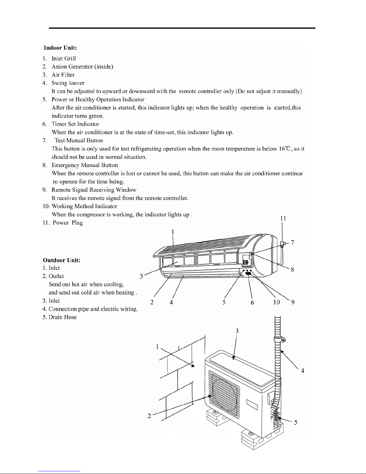
Description and function of main components and accessories
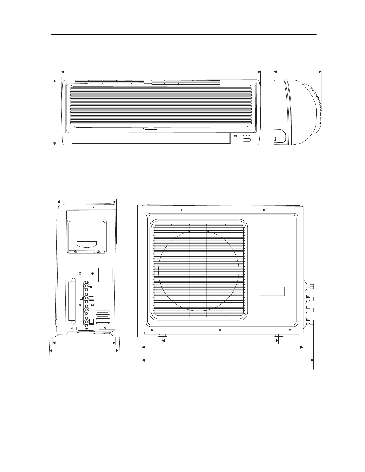
795
265
182
Net dimensions for outdoor unit
583
815
869
680
319.5
352
295
Net dimensions for indoor unit

KNOCK-DOWN DRAWINGS
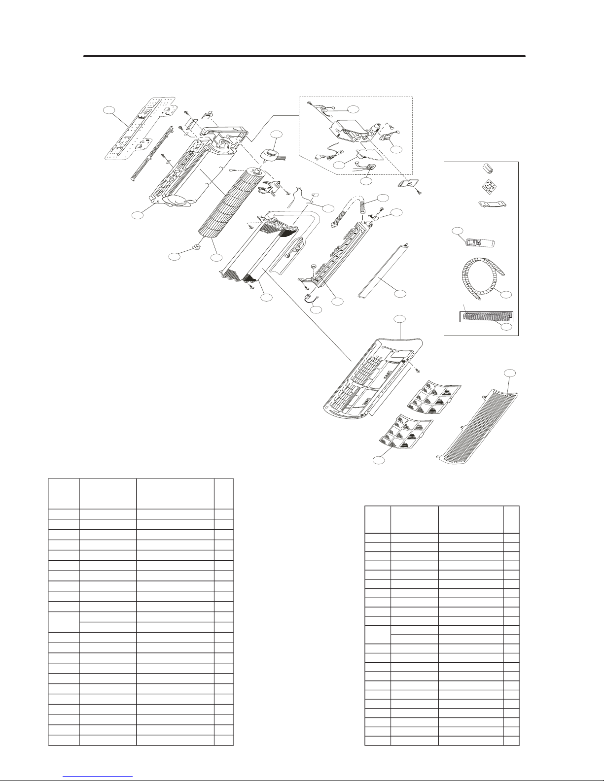
INDOOR UNIT
1
3
2
4
5
6
7
8
9
10
11
12
13
14
15
16
17
18
19
20
21
22
No. in
exploded
view
Spare parts
number
Spare parts description
in english
Qty
1 001A1232082 Inlet grille assy. 1
2 001A2400060 Air filter 2
3 0010
101525
Fron
t panel assy.
1
4 001A1232077 Flap 1
5 001A0900064 Drain pan assy. 1
6 001A0400055 Evaporator assy. 1
7 001A0300005 Bearing 1
8 0010202415 Cross flow fan 1
9 001A0100206 Frame assy. 1
10 001A1301216 Mounting plate 1
001A3000052 Fan motor 1
001A1431372 Motor cover 1
12 001A3800032 Transformer 1
13 0010403740 PCB 1
14 0010403686 Te rminal block 1
15 001A0600287 Receiver board 1
16 001A09000
11
Drain hose 1
17 001A30
00072
Swing
motor
1
18 0010403793 Remote controller
1
19 001A1434039 Drain tube 1
20 001A2400059 Air purifying
2
21 001A3900059 Sensor 1
22 0010400724 Negative ion generator 1
11
No. in
exploded
view
Spare parts
number
Spare parts description
in english
Qty
1 001A1232082 Inlet grille assy. 1
2 001A2400060 Air filter 2
3 0010101525 Front panel assy. 1
4 001A1232077 Flap 1
5 00
1A0900064
Dra
in pan assy.
1
6 001A0400055 Evaporator assy. 1
7 001A0300005 Bearing 1
8 0010202415 Cross flow fan 1
9 001A0100206 Frame assy. 1
10 001A1301216 Mounting plate 1
001A3000052 Fan motor 1
001A1431372 Motor cover 1
12 001A3800032 Transformer 1
13 0010403741 PCB 1
14 0010403686 Terminal block 1
15 001A0600287 Receiver board 1
16 001A0900011 Drain hose 1
17 001A3000072 Swing motor 1
18 0010403793 Remote controller
1
19 001A1434039 Drain tube 1
20 001A2400059 Air purifying
2
21 001A3900059 Sensor 1
22 0010400724 Negative ion generator 1
11
HKEL 261 XR
HKEL 351 XR
29
13
15
16
17
18
19
20
2
0
14
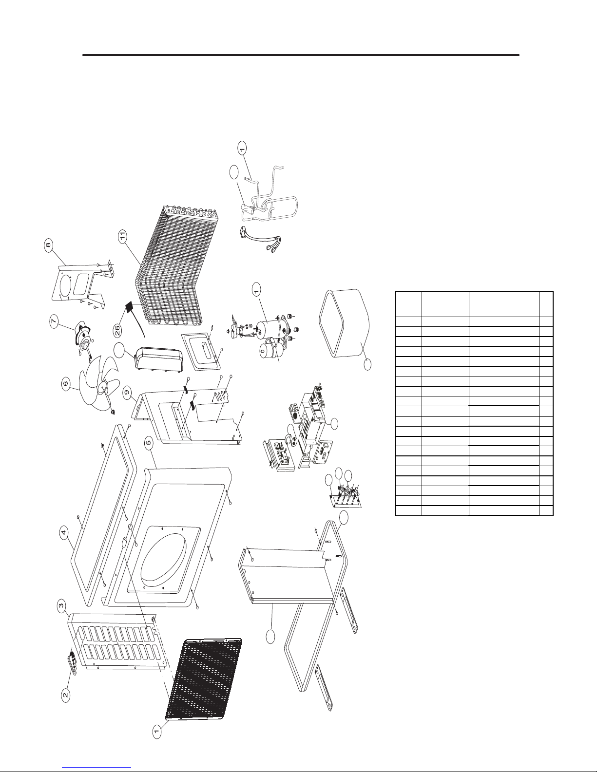
No. in
explode
d view
Spare parts
number
Spare parts description
in english
Qty
1
0
010203945
Front guard 1
2
001A14361
82
Handle 1
3
001A1101039
Left side panel 1
4
001A0100124
To p pane
l
1
5
0010101
525
Fro
nt panel
1
6
0
01A2331024
Axial fan 1
7
001A30007
6
Motor 1
8
001A1301133
Motor s
upport
1
9
0010101524
Right side panel 1
10
0010706971
Compressor 1
11
0010707166
Heat excha
nger
1
12
0010707160
Pipe assy. 1
13
0010703
520
4-way valve Assy 1
14
0010806619
Electric box Assy 1
15
001A1301304
Split board 1
16
0010806754
Bottom plate assy 1
17
001A1301127A
Stop valve support 1
18
0010705
987
Stop valve 2
19
0010705988
Stop valve 2
20
001A17621544
OUTDOOR UNIT
HCNL 531 XR

ELECTRICAL CONTROL

catalog
1. application range
2. operation modes
3. strength operation
4. mute operation
5. air refreshing
6. timing operation
7. dormant mode
8. urgent switch input
9. low load protection control
10.high load protection control
11.low heating processing
12.indoor and outdoor communication
13.remote control signal codes
14.abnormal operation of indoor system
15.EEPROM control
16.malfunction list resume (to 0010403739/3740)
17.abnormal conditions confirmation
18.special functions
19.airflow conducing board control
20.other additional functions
appindex
1. Application range
conditionic and its expanded types.
Note: Close S2 and open S1 before connecting to the power source. Enter the time-cut mode after
the connection.
Close S1 and open S2 before connecting to the power source. Enter the time-cut mo de after the
connection.
2. Operation modes.
1. Full-automatic approach.(
After the air conditonic is switched on, when the system is at the automa tic option, the
appropriate operation mode will be chosen according to the difference between the set temperature
and the indoor temperature . In the following option conditions, Tr stands fo r indoor temperature
and Ts stands for set temperature.
The system will choose the operation mode according to the following conditions when entering
into the automatic operation option for the first time.
Tr≥Ts-3℃ Choose the cooling mode
Tr<Ts-3℃ Choose the warming mode

Under the automatic option, the system will switch between the cooling and warming modes
according to the change of the indoor temperature. If the air conditionic is under the cooling mode,
when the set temperature for stopping th e compressor is reached, the compre ssor will be stopped.
The indoor temperature will be tested aga in 15 minut es after the s top of the co mpressor . At the
moment, if the tested temperat ure is un der the Tr<Ts-3℃ condition, the system will be switched into the
warming mode. If not, the system will remain in the cooling mode. If the air conditionic is under the warming mode,
when the set temperature for stopping th e compressor is reached, the compre ssor will be stopped.
The indoor temperature will be tested aga in 15 minut es after the s top of the co mpressor . At the
moment, if the tested temper ature is under the Tr(compensation value not included)≥Ts+3℃ condition,
the system will be switched into the cooling mode. If not, the system will remain in the warming mode. If the system
is stopped by a change on the set temperature, the decision of mode switching will be made 3 minutes later.
When the system is switched to the automatic option from other opti ons, if the operation
conditions changes ( new decision should be made before new operation), the system will be stopped
for 3 minutes and then enter the relative mode according to the inlet air temperat ure.
This mode has the timing fu nction an d dorman t function. Under the cooling m ode, the c ooling
dormant function is stimulated while the dormant heating function takes effects under the heating
mode.
This mode has the strength/ mute function. Under the cooling mode, the cooling st rength function i s
stimulated while the strength heating function takes effects under the heating mode.
The airflow speed control can choose the low, medium, high or automatic option and send the
airspeed signal to the outdoor system.
Automatic lowered airflow direction board. (the same with the cooling or he ating mode.)
2. Cooling operation mode
* Temperature control range: 16℃---30℃
* Temperature difference: ±1℃
* Control features: When Tr(inpu t airflow)>Ts(set temperature)℃, the compressor will be
opened,the indoor fan will operate at the set speed and the mode signal will be sent to the outdoor
system. When Tr(input airflow)< Ts(set temperature)℃, the compressor will be opened,the indoor
fan will operate at the set speed and the mode signal will be sent to the outdoor system. The system
will keep the original status if Tr= Ts.
* Airflow speed control: (temperature difference 1℃)
Automatic: When Tr>=Ts+3℃, hi gh speed.
When Ts+1℃=<Tr<Ts+3℃, medium speed
When Tr<Ts+1℃, low speed
When the sensor is off, low speed
When the airflow speed has no delay from the high to low switching, the speed should be delayed
for 3 minutes (remain at high speed for 3 minutes.) before the next switch.
Manul: When the system is operating, you can set the high, medium or low speed manually. ( When
the sensor is on or off, the system will chan ge the speed 2 seconds after rec eiving the signal.)
*Airgate location control: the loca tion for the airga te can be set accordin g to your needs.
*Defrosting function: preventing the frosting on the indoor heat exchanger (when cooling or
demoisture). When the compress or works continu ously for 5 minute s (adaptable in EE PROM) and the

temperature of the indoor coils has been below zero centigrade for 10 seconds, the compressor will
be stopped and the malfunction will be recorded in the malfunction list. The indoor system will
continue to run. When the temperat ure of the indoor coil is raised to 7℃, the comp ressor will be
restarted again (the prerequirement of 3 minutes’ delay should be satisfied.)
* timing system on/off function.
* Dormant control function.
* Under the cooling mode, the outdoor sy stem will proces s the frequency conversing of the
compressor according to t he set temperature, indoor temperat ure and the indoor heat exchange
temperature. (refer to the specification for the outdoor system.)
3. Demoisture mode.
* temperature control range: 16---30 ℃
* temperature difference: ±1℃
Control feature: send the demoisture signal to the outdoor system.
When Tr>Ts+2℃, the compressor will be turned on, the indoor fan will operate at the set speed.
When Tr is between the Ts and Ts+2 ℃, the outdoor system will operate at the high demoisture
frequency for 10 minutes and then at the low demoisture mode for six minutes . The indoor fan will
operate at low speed.
When Tr< Ts, the outsystem will be stopped , the indoor fan will be stoppe d for 3 minutes and
then turned to the low speed option.
All the frequency converses have a ±1℃ difference.
* Wind speed control: Automatic:
When Tr >= Ts+ 5℃, high speed.
When Ts+3℃≤Tr< Ts+5℃, medium speed.
When Ts+2℃≤Tr< Ts+3℃, low spee d.
When Tr<Ts+2℃, light speed.
If the outdoor fan stopped, the indoor fan will be paused for 3 minutes.
If the outdoor fan stopped for more than 3 minutes and the outdoor system still operates, the system
will be changed into light speed mode.
When the airflow speed has no del ay from the high to lo w switc hing, the speed should be dela yed
for 3 minutes (remain at high speed for 3 minutes.) before the next switch.
Manual: When the sensor is off or Tr< Ts+3℃, the manual operation can not be made. (obligatory
automatic operation.)
*Airgate location control: the loca tion for the airga te can be set accordin g to your needs.
*Defrosting function: preventing the frosting on the indoor heat exchanger (when cooling or
demoisture). When the compress or works continu ously for 5 minute s (adaptable in EE PROM) and the
temperature of the indoor coils has been below zero centigrade for 10 seconds, the compressor will
be stopped and the malfunction will be recorded in the malfunction list. The indoor system will
continue to run. When the temperat ure of the indoor coil is raised to 7℃, the comp ressor will be
restarted again (the prerequirement of 3 minutes’ delay should be satisfied.)
* coil protection (synchronic overheating protection) are installed for the four directions latch
malfunctions when demoisturing.
* timing system on/off function.
* Dormant control function.

4. Heating operation mode.
* temperature control range: 16---30℃
* temperature difference: ±1℃
* control feature: send the heating signals to the outdoor system.
If Ts≥Tr+1℃, the outdoor compressor is turned on.
If Tr≥ Ts+1℃, the outdoor system is turned off. However, with the previous 5 minutes after
the starting-up, the system ca n’t be stopped even if the changed Tr reached the Ts. The system
can be turned off after these 5 minutes.
If the set temperature is changed to the room temperature, the system will be stopped at once.
If the system is under the heating or automatic heating mode, the set temperature will be added
a compensated value, which usually makes the set temperature on the thermostat have 3 degrees’
compensation.
*Indoor fan control
manual control: You can choose high, medium, low and automatic speed control.
Automatic: When Tr<Ts, high speed.
When Ts=<Tr=<Ts+2℃, medium speed.
When Tr> Ts+2℃, low speed.
When the airflow speed has no del ay from the high to lo w switc hing, the speed should be dela yed
for 3 minutes (remain at high speed for 3 minutes.) before the next switch.
*Airgate location control: the location for the airgate can be set according to your needs.
. Coldair proof operation
1. when the indoor temperature is below 23 centigrades, the indoor fan will be off, when the
temperature is above 23 centigrades, the indoor fan will run at a slight speed.
2. If the coil temperature is above 38 centigrade, the fan will run at the set speed.
3. If the coil temperatur e doesn’t reach 38 centigrade 4 minutes after the start-up of the
slight airflow, the fan will run at the set speed. (Whether the coil temperature falls or not
after the starting up of the slight airflo w, the set speed is stimulated if the tem perature
doesn’t surpass 38 centigrade.)
4. When the compressor works, the i ndoor fan will run at the set speed when the spe ed of the
slight airflow reached the set speed.
Set airflow
38℃
Slight airflow
23℃

* Residue heat sending. The indoor fan will send the residue heat at a low speed for 20 seconds.
If the Tc(indoor coil)< 20 centigrade, the indoor fan will be stopped at once.
* If the system is stopped when the set temperat ure is reached, th e indoor fan will run at
a slight speed within the 3 minute’s waiting mode until Tc< 20 centigrade.
* If the indoor system is turned off, the air direction board will be closed after the stop
of the indoor fan. (the indoor fan will be stopped immediately if there is a malfunction.)
* Defrosting: After receiving the defrosting signal of the outdoor system, the indoor fan will
be stopped, and the malfunctions of the indoor coils and the indoor sensors will be neglected.
In the defrosting period, the default indoor temperature is 10 centigrades, the coil
temperature will be 20 centigrades. With in the defrosting period and the proceeding 2 minutes,
the temperature sensor will not test the abnormalities(including the indoor coil and the indoor
temperature sensor) and the cold air proof operation will be stimulated after these two minutes.
* Overload protection syst em can protect the coil from overheating. The outdoo r system will
be stopped if the 10s continuous tests show that the indoor temperature is above 65 centigrades
(accomdable in EEPROM), a nd the ove rheating ma lfunction is to be rep orted. When the indoor
temperature is below 42 centigrades(accomdable in EEPROM) and the system has been stopped for
more than 3 minutes, it means that the malfunction has been cleared and the outdoor system
will be started again.
* Under the cooling mode, the outdoor sy stem wi ll proces s the fre quen cy conver sing of the
compressor according to the set temperature, indoor temperature a nd the indoor heat exchange
temperature. (refer to the specification for the outdoor system.)
5. Low heating processing.
When the four direction latch switch doesn’t work or the compressor restarts (despite the
defrosting operation and the proce eding 3 minutes) at the heat ing mode, if the heat exchang er
temperature is below "THHOTLTH"(-4.5℃)for "TMHOTLTH"(90seconds), the compressor will be paused
for 3 minutes. The indoor temperature will be restored at " THHOTLTH "(-4.5℃).
3. Strength/ mute operation
* When the system operates, if there is onl y a strength setting and no mute settings, the indoor
fan will have an airflow speed processing and the outdoor fan will have a stre ngth processing. But
if the system has both the strength settin g and the mute set ting, only th e indoor fan will ha ve
the speed processing accordingly and the outdoor fan will not operate any process. If there is only
a mute setting and no strength settings, the indoor fan will have an airflow strength processing
and the outdoor fan will have a speed processing.
* The realization of indoor fan functions: The indoor system sends the strength or mute signal to
the outdoor system. The indoor fan with a set strength will operate at the set str ength speed and
the indoor fan set into a mute mode will send slight airflow.
*1. strength operation
a. the system enters the mode after receiving the ‘strength signal’.

Send strength operation signal to the outdoor system.
Strength operation for 15 minutes.
The strength operation stops or finishes after the 15 minutes.
The mode change finishes the strength operation.
Entering ‘mute’, you can have normal operation or signal control such as timing to finish the
strength operation.
When the system is at the automatic option with the strength/ mute function, if the system enters
the cooling mode, the cooling strength/ mute function will be offered; if the system enters the
heating mode, then the heating strength/ mute function will be offered; if the system enters the
airflow mode, there will be no strength/ mute function.
b. strength heating:
temperature accommodating function.
The airflow is offered by strength heating (adaptable in the EEPROM)
In the defrosting mode, the outdoor fan doesn’t receive strength operation signals.
15 minutes after the stren gth opera tion, the compressor can’t be turned off wi thin 10 minutes .
(except the malfunctions and the off singals)
c. strength cooling:
temperature accommodating function.
The airflow is offered by strength cooling (adaptable in the EEPROM)
The low load protection can’t be stimulated within the 3 minutes after the start up of the
compressor.
d. Demoisture, strengthless airflow operation.
*2. Mute operation
a. the system enters the mode after receiving the ‘mute signal’.
b. send the mute signal to the outdoor system.
c. mute heating:
When the compressor operates, the airflow speed is mute speed. EEPROM is adaptable.
*After the compressor is turned off, the airflow speed can be controlled according to the following conditions.
1. If the system is turned off with a remote control or under an urgent condition, the fan speed will be changed
into light speed within 20 seconds. Then, the fan will stop 20 seconds later. The airflow direction board will be closed
after the 20 seconds’slight airflow.
2. If the system is turned off by a malfunction, the fan will be stopped at once.
3. If the sensor is turned off, the fan will operate at a slight speed.
4. Mute cooling.
Mute cooling: the airflow speed will be mute speed. EEPROM is adaptable.
5. Mute operation can not work under the demoisturing and airflow-sending operation.
4. Air refreshing
After receiving the signal from the remote control, the power indicator turned to yellow green ( the
indicator is oringinally red). If the fan operates, the negative ion generator operates to realize
the negative sending function.

If the indoor fan stops, the negative ion generator is turned off.
When the negative ion generator is turned off, if the air refreshing system is turned on, the negative
ion generator will be turned on when the fan operates.
5. Timing.
You can set 24 hours’ on/off timing accordingly. After the setting, the timing indicator will be
lightened. Also, the light will be turning off after the timing is finished. The followings are
several timing methods.
1.1 system /on timing: The timing indicator will be ligh tened and the indoo r system is under
the waiting mode. The light will be turned off when the timing is finished and the rest of the system
will operate under a normal condition. The timing starts since the last reception of the timing
singal. You can have the dormacy setting under the timing mode, the order of your settings will
be operated according to the timing settings.
1.2 system /off timing: When the system is turned on, the timing indicator is lightened, the rest
of the system will operated under a normal condition. When set time comes, the indicator light will
be turned off and the system will be turned off. If you have set the dormant functions, the order
of your settings will be operated according to the timing settings.
1.3 system /on and off timing: The settings will be completed according to the orders.
6. Dormant operation
*1. According to the option, after you have set the domant setting, the timing indicator will be lightened.
*2. Under the cooling/ demoisture operation, after the setting of the dormant operation, the set temperature will be
raised for 1 centigrade after 1 hour’s operation and will be raised for 1 centigrade 1 hour later. The system will keep
this status for 6 hours and then close.
*3. Under the heating mode, after the setting of the dormant operation, the et temperature will fall 2 centigrades after
1 hour’s operation and will fall 2 centigrades 1 hours later. 3 hours after the preceding operations, the set temperature
will be raised for 1 centigrade and the system will keep this status for 3 hours and then close down.
*4. Indoor fan control under the dormant operation.
If the indoor fan is at the high speed before the dormant operation setting, the speed will be turned to medium after
the setting. If the fan is at the medium speed before the dormant setting, the speed will be turned to low after the
setting. If the fan is at the low speed before the dormant setting, the speed will not change.
7. Urgent on/off input
*1. Press the urgency button the buzzer will ring. The system will enter the automatic mode if you don’t press the
button for more than 5 seconds.
*2. If you press the urgency button for more than 5 seconds, the buzzer will ring twice. At the time, if you loose the
button, the system will enter test operation function. The indicated frequency of the test operation function is 58Hz
and the airflow speed is high. The test operation will be finished after 30 minutes and the system will be closed.
During the test period, the system will quit the test operation after receiving the signal from the remote control. The
low load protection can’t be stimulated her e.
*3. If you press the urgency button for more than 10 seconds, the buzzer will ring for 3 times. If you loose the button,
the malfunction list will be presented, on which the last system malfunction is to be revealed. The malfunction signal
can only be eliminated after the the system has received the indoor or outdoor malfunction correcting singals. The
malfunction list doesn’t receive any remote control signals except the stop signal. If there is no malfunction, no

signals are tobe revealed, but the buzzer still rings.
*4. If you press the urgency button for more than 15 seconds, the buzzer will ring only once. The system will keep
the present status and can receive on/off signals.
*5. When you press the urgency button. Within 15 seconds, no remote signals can be received. After 15 seconds, just
like the remote signal reception mode under normal conditions, the normal remote signals can be received.
8.
opposite operation modes exist of indoor system
When the outdoor system operates, if the indoor system operation differs from the outdoor system, the abnormal
operation malfunction will be reported. 10s after the report, the indoor system will be closed.
Outdoor system mode Indoor system mode conflicts
cooling heating yes
cooling cooling no
cooling airflow no
heating heating no
heating airflow yes
heating cooling yes
9. EEPROM control
When outdoor system is connected to the power circuit, if the EEPROM value differs from the tested value, then the
EEPROM is abnormal.
When the indoor system receives EEPROM the abnormal reading and writing signals from the outdoor system, the
abnormality of the outdoor EEPROM is confirmed.
At the time, the control and urgency signals can not be received.
The problem can be solved through switching off the power supply.
10. Malfunction list resume.
Nothing is presented if there is no code list.
For the malfunction modes, refer to the urgency button specification.
The remote control only receives the sigals for stop. According to the signals, the malfunction
resume presentation finishes.
The resume restores after the power supply restores.
11. abnormality confirmation approaches.
11.1 indoor temperature sensor abnormality: under the operation, the normal temperature ranges from 126 degree to
-31 degree. When the temperature goes beyond this range, the abnormality can be confirmed. If the temperature goes
back into the range, the system will automatically resume.
11.2 indoor heat interaction sensor abnormality: under the operation, the normal temperature ranges fro m 126 degree
to -31 degree. When the temperature goes beyond this range, the abnormality can be confirmed. If the temperature
goes back into the range, the system will automatically resume.
11.3 indoor fanmotor malfunction.
When the indoor fan signal is output, if there is no feedback within 2 minutes, the abnormality can be confirmed.
11.4 Outdoor malfunction processing.
When the outdoor malfunction signal is sent to the indoor system asking for malfunction report, the operation LED

light will report the malfunctions by flashing, the times of flashing stands for the outdoor malfunction codes. If there
is no malfunctions within the outdoor system, the indoor system will continue to run.
11.5 transmission abnormality.
If the indoor system can’t receive the outdoor system for 5 minutes, the communication abnormality can be
confirmed and the outdoor system will be stopped. 170 seconds later, the malfunction can be cleared, 3 minutes after
the turning down of the system can it be started again and the test and inspection is to be restrated.
12. Special functions
*1.Single indoor system operation
* Enter condition: Under the no-electricity cut compensation condition, press the dormant keys
for 6 times within 7 seconds, the system will feedback with 6 rings.
* After the system enters the separate indoor system operation mode, the indoor system will operate
according to the set mode and neglect the communication signals of the outdoor system. However,
it has to send signals to the outdoor system.
* Quitting condition: This mode can be quitted after receiving the quitting signal from the remote
control or urgency system. The indoor system thus can quit the single operation mode.
* Under the single indoor fan operation, the preset outdoor status is as the follows.
The compressor frequency is 58 hz, there is no error or non-defrosting signals, and the sensors
are at the normal temperature.
* Malfunction happens on the two sensor of the indoor system. The indoor heat interaction temperature is fixed at
47 centigrade and the ambient temperature is fixed at 25 centigrade.
* When the single indoor system operation is set, after receiving the signals from the remote control, all kinds of
output control (such as negative ion) can be set normally and cancelled. The screen board will show all kinds of set
conditions ( the setting and canceling of negative ions, the setting and canceling of the timing functions, etc.), among
which the LED will be lightened after entering the single indoor system.
2. Power cut compensation.
* Entering condition: Press dormant button 10 times within 7 second, the buzzer will ring 4 times and the present
system status will be stored into the EEPROM of the indoor system.
* After entering the power cut compensation mode, the processing of the indoor system should be as the followings:
Remote control urgency singal: operate according to the remote control and the urgent conditions, the present status
will be stored into the EEPROM of the indoor system.
* Quitting conditions: Press dormant button 10 times within 7 seconds and the buzzer will ring twice.
3. Fixed frequency operation.
** 1. Fixed cooling: a. under any condition: high speed cooling, set 16℃, press temperature ‘-‘ key
and the set key at the same time,the bu zzer will ring 2 times and the system will enter the fixed
frequency operation.
b. The proceeding programs are as the follows:
Entering the fixed frequency operation, the fixed indication is presented in the communication.
c. Quitting condition: The f ixed frequency cooling c an be quitted after rece iving the remote
signal, and the system will enter the remote setting status.
*2. Medium cooling: under any condition : a. high spe ed cooling, set 16℃, press the dormant key
4 times within 7 seconds and the buzzer will ring 5 times. The system then enters the medium mode.
b. The proceeding programs are as the follows:

Entering the medium cooling operation, the medium power is presented in the communication.
c. Quitting condition: The m edium co oling ca n be quitte d after re ceiving the remo te signal, a nd
the system will enter the remote setting status.
*3. minimal cooling: a. G code (the remote controller) entering condition: press the dormant key
8 times within 7 seconds and the buzzer will ring 7 times. The system then enters the minimal mode.
b. The proceeding programs are as the follows:
Entering the minimal cooling operation, the minimal cooling is presented in the communication.
c. Quitting condition: The minimal cooling can be quitted after receiv ing the remote signal, and
the system will enter the remote setting status.
** 1. Fixed heating: a. under any condition: high speed heating, set 30℃, press temperature ‘+‘ key
and the set key at the same t ime and the buzzer will rin g 2 times.The system will e nter the fixed
frequency operation.
b. The proceeding programs are as the follows:
Entering the fixed frequency operation, the fixed indication is presented in the communication.
c. Quitting condition: The fixed frequency heating can be quitted after receiving the remote signal,
and the system will enter the remote setting status.
*2. Medium heating: under any condition : a. high spe ed heating, set 30℃, press the dormant key
4 times within 7 seconds and the buzzer will ring 5 times. The system then enters the medium mode.
b. The proceeding programs are as the follows:
Entering the medium heating operation, the medium power is presented in the communication.
c. Quitting condition: The m edium he ating ca n be quitte d after re ceiving the remo te signal, a nd
the system will enter the remote setting status.
*3. minimal heating: a. G code(the remote controller) entering condition: press the dormant key
8 times within 7 seconds and the buzzer will ring 7 times. The system then enters the minimal mode.
b. The proceeding programs are as the follows:
Entering the minimal heating operation, the minimal heating is presented in the communication.
c. Quitting condition: The minimal heating can be quitted after receiv ing the remote signal, and
the system will enter the remote setting status.
13. Other additional functions
*1. Self test function, time-reducing function.
1-1 close the code switch S1 and open switch S2 before connecting to the power circuit and the indoor system enters
the time-reducing function, one minute is reduced as one second.
1-2 close the code switch S2 and open switch S1 before connecting to the power circuit and the indoor system enters
the self-test program 3 seconds later. The airflow direction board is closed.
* After the entering into the self test program, the power light will be lighted for one second, and then the clearing
light will be lighted for 1 second. Then, the timing light will be lighted for one second. At last, the dormant light will
be lighted for 1 second. Then the system will be in the off status.
* The indoor system will keep the communication with the outdoor ever since the flash of the self test light.
* The fan motor operates at a medium speed during the self testing.
*2. The display function

Three lights display. ( one of the lights is a double colour light, the light board is 287 light board.)
z Receiving the start up signal, the power light will be lighted, red colour.
z Indoor system requires start up, the operation light will be lighted. (The indoor system can only judge the indoor
condition, not the operation status of the outdoor system.)
z When setting the timing option and the dormant option, the timing light will be lighted; when setting health
option, the power light will turn to yellow green.
z Under the start up malfunction mode, if it is an indoor malfunction, the timing light will flash; if it is an outdoor
malfunction, the operation light will flash. Please refer to the malfunction code list.
*3、airflow speed setting communication.
When the indoor airflow speed changes, the speed option will be sent to the outdoor system. There are 5 options
in all: strong, high, medium, low, slight.
14. Appendix
Appendix 1 : The malfunction code for the indoor and outdoor system interaction
malfunctions.
Indoor system malfunction codes
malfunction
codes
malfunction
1 Indoor temperature sensor system break
2 Indoor heat interaction temperature
sensor system break
3 Frosting under the cooling mode
4 Overheating under the heating mode
5 Inefficient communication between indoor
and outdoor system
6 Momental power cut
7 non
8 No feedback from the indoor fan(PG or DC
motor only)
12 Malfunction in reading or writing E2ROM

Outdoor malfunction codes
Malfunction
codes
Malfunction
1 Ambient sensors circuit break
2
Hot temperature exchanger sensor circuit
breaks or shorts.
3
Outlet temperature sensor circuit breaks
or shorts.
4 DC compressor feedback.
5
Outdoor system communication
malfunction.
6 Current overcharge.
7 No load.
8 Overloaded/ under loaded voltage.
9 DC compressor failure.
10 Refrigerating overload
11 Defrosting mode
12 IPM protection
13 E2 ROM reading failure
14 E2 ROM coining failure
15 Non
16 NO AC power.
17 Aspiration sensor circuit breaks
19 DC compressor speed control failure
21 Coil 1 sensor circuit breaks or shorts
22 Coil 2 sensor circuit breaks or shorts
31 System A communication malfunction
32 System B communication malfunction

OUTDOOR SYSTEM FUNCTIONS
The outdoor system will decide the operation mode based on the principle of ‘first order
preferred’ according to the startup signals of the two indoor systems.
a) cooling: Under the cooling operation, the four direction latch will not be closed.
The outdoor fan will operate at the cooling mode. The compressor will operate under
the cooling frequency.
b) heating: Under the heating operation, the four direction latch will be closed. The
outdoor fan will operate at the heating mode. The compressor will operate under the heating
frequency. When frosts appear at the outdoor sys tem, the system will e nter into the
defrosting operation automatically. After the completion of the defrosting, the system
will be resumed.
1. heat defrosting operation
1.1 Under the heating operation, wh en the indoor heat interaction temperatu re is below the
ambient temperature and the heat inter action temperature is below zero centigrade, the
frosts will appear on the heat exchanger. When the aggregated frost affects the heat
interaction, the defrosting operation will begin.
1.2 frost confirmation condition. When either of the following condition appears, the system
will enter the defrosting mode.
b) continuous operation for 47 minutes and Ta≥5℃, if Te
≤-3℃ for 2 minutes.
b) continuous operation for 47 minutes and Ta<5℃, if Te≤-7℃ for 2 minutes.
c) continuous operation for 47 minutes and Ta<-3℃, if Te≤-9℃ for 2 minutes.
d) If Ta≤-3℃ and the compressor worked for 3 hours without a defrosting operation, the
system will process the defrosting for one time.
1.2.1 Defrosting process: After entering the defrosting operation, the compressor and the fan
will be stopped. The four direction latch will be opened 30 seconds later. And the compressor
will restart 10 seconds later. The system begins the defrosting operation .
1.2.5 defrosting quitting condition:
i) Time control: Defrosting time lasts 10 (EEPROM) minutes, the defrosting operation ends.
ii) Heat interaction control: When Te≥14℃(
EEPROM
), the defrosting operation ends.
1.2.6 Defrosting quitting process
After the completion of the defrosting, the compressor stops. 50 seconds later, the four
direction latch changes direction. 10 seconds later, the compressor will start and the original
heating operation resumes.
1.2.7 After the entering into the frosting mode, the compres sor will operat e at least for
1 minutes before stopping th e defrosting. (Th e timing starts as the four direction latch
starts.)
1.3 Outdoor main relay control
The outdoor main relay closure will be delayed for 2 seconds after connecting to the circuit.
1.4 Outdoor airflow control
1.4.1 airflow control at the cooling mode.
After the compressor is turned on fo r 5 seconds, the outdoor fan will start at a high sp eed.
10 seconds later, the speed w ill be controlled according to the outdoo r ambient temperature.
If the outdoor has only two option, M operates on H and L operates on L.

When the outdoor speed is M or L, the speed will change according to the heat interaction
temperature. The status will be checked every minute.
Ta>28℃,high speed
26℃<Ta<28℃ ,high/ low speed
Ta<26℃: Te≧40℃,high speed
37℃≦Te<40℃,high/ medium speed
35℃≦Te ,medium speed
30℃≦Te<35℃,medium/ low speed
Te<30℃,low speed
1.4.2 the speed control under the heating mode
The outdoor speed varies according to the outdoor ambient temperature. M operates on H under
the two option mode.
Ta>24℃,low speed
24℃>Ta>20℃,low speed/ medium speed
Ta>16℃,medium speed
16℃>Ta>10℃,medium/high speed
Ta<10℃,high speed
1.5 Outdoor four direction control
Under the cooling mode, the outdoor four direction latch is not closed. Under the heating mode,
the latch can be closed. When the heat ing compressor stops, the four direction latch will be
closed 100 seconds later. The latch control under the defrosting operation has been discussed
in the ‘defrosting operation’.
1.7 compressor frequency control
1.7.1 fixed test frequency
To fixing test frequency operation of the outdoor system.
the indoor system can be controlled manually. (refe r to the indoor system sp ecification).
1.7.1.1 If the indoor system has the fixed frequency test operation function, then the outdoor
system will calculate the fixed frequ ency according to th e number of the turned on sy stems
and operate on the calculated frequency until the indoor system quit the test operation. When
the two indoor systems ar e turned on at the sam e time, the outdoor syst em will ent er the
operation mode if either of the indoor systems sends the fixed test frequency.
Ta =24℃
Outdoor speed:
Ta =16℃
Ta =10℃
Ta =20℃
L
M
H
M L

i) The outdoor fixed frequency is set according to the indoor system signals. The operation
is on the frequency stored in EEPROM
ii) The cooling and heating value under the double system operation
Under the single system fixed frequency test, the outdoor system will operate according to
the turned-on indoor system status. The operation will on the frequency relative to the status.
Under the double system operation test, the outdoor system will automatically operates on the
double system fixed test frequency.
1.7.2 Normal operation frequency control
Under the outdoor system normal operation, the fixed frequencies of different indoor systems
should be tested according to the different capacity of the respective indoor systems. Then
the outdoor system will dec ide the opera tion frequenc y according t o the fixed fr equencies,
the difference between set temperature and the indoor temperature and the indoor fan speed.
1.8 malfunction and protection
1.8.1 Three minutes’ waiting mode protection
1) No matter caused by which condition, the outdoor compressor is not allowed to be restart
within 3 minutes after a compressor shut down.
2) If the compressor shut down is caused by malfunctions and the malfunction is corrected
3 minutes after, the compressor can restarted of the correction at once.
1.8.2 Intelligent power module protection.
i) Under the compressor operation, if the IPM protection happens under the voltage over/under
loading, over heating or current over charge, the compressor will stop and res tart 3 minutes
later.
ii) If the IPM protection happens 4 times continuously, the compressor will be totally turned
off and can be restarted only by a second connection to the power supply.
1.8.3 Sensor malfunction protection.
i) There are 6 sensors in the outdoor syst em. The outdoor system will stop if any of the six
sensors has malfunctions. The malfunction will be reported respectively.
ii) After the malfunction has been corrected for 3 minutes, the system can be rest arted.
Outdoor restriction condition codes display:
When the outdoor system operates, because of the various temperature or electrical device
restrictions, the compres sor has to ensure the maximal output withi n a safe frequency range.
This restriction condition only rep resent the most possible condition at the t ime, can only
be used as a reference in experiments.
1# Normal, no restriction
2# Power voltage restriction
3# outdoor heat interaction restric tion under the cooling mode; in door heat
interaction under the heating mode.
4# main current restriction
5# outlet temperature restriction
6# indoor heat interaction temperature restriction. (frosting preven tion)
7# Indoor fan speed restriction
8# Outdoor frequency conversing voltage restriction
1.8.4 The malfunction codes:

After the stopping of the system, the flashing time of the LED02 is the malfunction
code.
For example: Malfunction N.O 4
2.5sec 2.5sec
1# Ambient sensors circuit break.
2# Hot temperature sensor circuit breaks or shorts.
3# Outlet temperature sensor circuit breaks or shorts.
4# DC compressor feedback.
5# Outdoor system communication malfunction.
6# Current overcharge.
7# No load.
8# Overloaded/ under loaded voltage.
9# DC compressor failure.
10# Refrigerating overload.
11# Defrosting mode.
12# IPM protection.
13# E2 ROM reading failure.
14# E2 ROM coining failure.
16# NO AC power.
17# Aspiration sensor circuit breaks.
19# DC compressor speed control failure.
21# Coil 1 sensor circuit breaks or shorts.
22# Coil 2 sensor circuit breaks or shorts.
31# System A communication malfunction.
32# System B communication malfunction.
Dealing with the malfunctions
4# Compressor feedback malfunction: Check the main board CN301 and the module jack CN3.
Check the CN04 on the main board and test the output of 15V DC current between the pins
of CN04. Check the location of the chip COM01 at the back of the mainborad, to see if
there is any circuit shorts. Check the states of the 3 phases of the modules. If the feedbacks
of all the checks and tests are normal, then replace COM01.
5# Outdoor system communication malfunction: check the module jack CN401 on the
main board, to see if the conducts of the jack are normally connected with
the terminal stripe. Test if there is a 5V DC current between the pin 8 and
pin 16 of IC03 on the main board. Check if the pin 3 and pin 13 of this chip
are correctly connected with the pin 44 and pin 45 of the IC01, to test if
there is any circuit shorts. Test if there is any communication wave output
at the pin 4 of PQ 404 and PQ 408 and at the pin 2 of PQ403 and PQ 407 and
if there is any circuit shorts on the systems of the surrounding devices ( the
misconnect between the live line and the zero line.)
6#. Current overcharge: Test if there is any circuit block on the system. Test the 4 diodes

D501-D504 on the main board with a multimeter. Test if there is any 5v circuit shorts at
R501-R503 and D-505. Replace device CT501.
7#. No load: Test the 4 diodes D501-D504 on the main board with a multimeter. Test is there
is any circuit short with GND at R501-R503 and D505( special focus on the possible circuit
short condition the terminal A of D502 and terminal K of D504). To test if there is any
formation of resistance or GND circuit short at the capacitor C501. Replace device CT501.
8# Overloaded/ under loaded voltage: Test if there is 310V DC between the terminal P and N
of the program module. Test if there is any circuit short at R301-R304 , R324 and R325.
Test if there is any formation of resistance or GND circuit short at the capacitor C304.
9# DC compressor start-up failure: Please restart; Check if the input and output at 7805(IC04)
is correct. Check the status of the module on the module board. (the normal reading of the
diode mode on the multimeter should be 0.45 at the P, N, U, V, W disconnect
terminals.);Check the voltage of C4,C5,C6 on the module board is 15V or not.
10#. Refrigeration overload: the temperature of pipe is too high,if the malfunction is
reported frequency, check the refrigerant is enough or not.
11# Defrosting condition: After the completion of the defrosting, the system will return to
normal.
12#. IPM protection: check if the system circuits are at normal condition. Check if there is any
GND short at R08 on the main board, to test if there is any formation of resistance or GND
circuit short at the capacitor C02, or any other protection modes caused by temporal current
surge as a result of inappropriate operation or other reasons.
13#,14# malfunctions: Check if the installation of IC05 on the main is correct. (if the installation
is reversed), and if there is any break at the back of the main board. Replace IC05 directly.
16# No AC power: Check the power supply.
19#DC compressor speed control failure: Restart the compressor after it is turned of for a while.
If the restart doesn’t work, refer the suggestions of NO 9 and NO 4.
31# and 32# A/B system communication problem: please refer to NO 5 and check the indoor
system communication circuit.
vals can be controlled in E2.

CIRCUIT AND WIRING DIAGRAM

1 2 3 4 5 6 78
Title
Number Revi
s
Size
A3
Date: 31-Oct-2005 Sheet of
File: D:\backup-liupeng\ .DDB
刘朋的数据库 Drawn By:
R28
2K/1/4W
S3
R27
10K/1/4W
R25
1K/1/4W
R24
510/1/4W
R23
510/1/4W
R4
1K/1/4W
D7
1N4148
VCC
1
2
3
4
5
6
7
CN8
B7B-PH-K
C7
102/25V
R17
3k/1/4w
3
2
1
CN6
B3B-EH-A
P1
FUSE
3.15A
1
2
3
CN2
B3B-XH-A
A0
1
A1
2
A2
3
GND
4
SDA
5
SCL
6
WP
7
VCC
8
IC02
E2ROM24C01
K101
C114
102/50v
R127
1K/1/4W
R126
10K/1/4W
1
2
3
4
CN4
S4B-XH-A
+12
D8
1N4007
C10
2200u/25v
Z301
560v
C307
474/275V
VCC
C4
104/50v
Vin
1
GND
2
Vout
3
V1
7805
C3
104/50v
1
2
3
4
T301
1
2
CN3
5273-03A
CR1
8MHz
R14
1K/1/4W
R104
10K/1/4w
VCC
R105
1K/1/4w
C101
104/50v
R109
4.7k/1/4w
R110
4.7k/1/4w
C112
4.7u/50v
C111
4.7u/50V
VCC
1
2
3
4
5
6
7
10
11
12
13
14
15
16
9
8
IC04
MC1413P
5
4
3
2
1
CN1
B5B-PH-K-S
S101
speeker
N2
1815
L1
R130
4.7K/1/4W
R131
4.7K/1/4W
R132
10K/1/4w
R133
10K/1/4w
D1
1N4007
D2
1N4007
D3
1N4007
D4
1N4007
O2
TLP521
O3
TLP521
R7
1K/1/4W
R8
100K/1/4W
R9
2K/1/4W
C9
102/50V
VCC
R10
25K/3W
D6
1N4007
Z3
18V
C11
100U/50V
C12
473/50V
R11
4.7k/1/4W
D9
1N4007
C13
103/50V
R12
1K/1/4W
R13
1K/1/4W
R15
120/1/4W
C14
470U/25V
C304
1.2u/450V
1
2
3
4
5
CN5
B3P5-VH
VCC
O5
TLP3616
R18
120/1/2w
C16
102/630v
R6
560/1/4w
C1
104/50v
1
2
3
4
5
6
7
8
9
10
11
12
13
14
15
16
17
18
20
19
21
22
23
24
25
26
27
28
IC01
807
C8
102/25V
R16
1K/1/4W
C15
104/50v
2
3
1
IC05
MC34064
C17
1u/50v
R19
10k/1/4w
VCC
C18
104/25V
C2
104/25V
C5
100U/25V
C6
104/50v
VCC
R1
10k/1/4w
L2
R2
1k/1/4w
2
1
CN7
5289-2A
P2
RL1
JQ1a-12V
P3
+12
R3
270/1/4w
VCC
+12
+12
+12
C20
104/25V
C21
104/25V
VCC
D5
1N4007
N3
1815
1
2
3
CN9
B3B-XH-A
+12
R5
10K/1/4W
R20
10K/1/4W
R21
4.7K/1/4W
S1
S2
VCC
VCC
R22
5.1K/1/4W
R26
1K/1/4W
SELFKEY
SHORTKEY
AB_CODEChoice
SW3
POWER
TIME
RUN
SCL
SCII
SCIO
RECEIVE
RECEIVE
AIRLED
AIRLED
COM1
POW1
FAN
COM1
POW1
COM
POW
ACV
1A/1.85MH
ACV
2%
2%
SCIO
SCII
POW
COM
WIND
SW1
SDA
HEALTH
HALLP
WIND
SW1SW2
SW3
SW4
BUZZER
HEALTH
PG
AIR
SELF
SELF
SDA
SCL

1 2 3 4 5 6 78
A
B
C
D
8
7654321
D
C
B
A
Title
Number RevisionSize
A2
Date: 20-Jan-2006 Sheet of
File: C:\Documents and Settings\chengyongfu\ \BACKUP~1.DDB
桌面Drawn By:
R16
10K/1/4W
+5
R05
4.7K/1/4W
R401
1K/1/4W
C401
102/50V
R403
4.7K/1/4W
+5
C405
102/50V
R408
4.7K/1/4W
+5
R406
1K/1/4W
C413
102/50V
R418
4.7K/1/4W
C409
102/50V
R413
4.7K/1/4W
P404
SIGD
P401
SIGC
1
2
34
CT501
0057W
E501
220uF/16V
R417
1K/1/4W
C415
102/50V
D403
1N4007
C414
104/50V
ZD403
DZB30C
+5
R419
20K/1/4W
R420
1.8K/1/4W
PTC403
MZ2J102M
C416
103/50V
C412
103/50V
PTC404
MZ2J102M
R415
1.8K/1/4W
R414
20K/1/4W
+5
ZD404
DZB30C
C410
104/50V
D404
1N4007
C411
102/50V
R412
1K/1/4W
R407
1K/1/4W
C407
102/50V
D402
1N4007
C406
104/50V
ZD402
DZB30C
+5
R409
20K/1/4W
R410
1.8K/1/4W
PTC402
MZ2J102M
C408
103/50V
C404
103/50V
PTC401
MZ2J102M
+12
+12
+5
CS
1
SK
2
DI
3
DO4GND
5
ORG
6
DC
7
VCC
8
IC05
E2ROM
1
2
3
4
5
6
7
8
9
10
11
12
13
14
15
16
IC07
TD62003
1
2
3
4
5
6
CN11
B6B-XH-A
1
2
3
4
5
6
CN12
B6B-XH-A
1
2
3
4
5
6
CN10
B6B-XH-A
1
2
3
4
5
6
CN09
B6B-XH-A
1
2
3
4
5
6
7
8
9
10
11
12
13
14
15
16
IC06
TD62003
+5
C207
104/50V
R207
4.7K/1/4W
E207
1uF/50V
R215
10K/1/4W
C206
104/50V
R206
47K/1/4W
E206
1uF/50V
R214
10K/1/4W
R213
10K/1/4W
E205
1uF/50V
R205
4.7K/1/4W
C205
104/50V
C204
104/50V
R204
4.7K/1/4W
E204
1uF/50V
R212
10K/1/4W
R211
10K/1/4W
E203
1uF/50V
R203
4.7K/1/4W
C203
104/50V
C202
104/50V
R210
10K/1/4W
R202
4.7K/1/4W
E202
1uF/50V
C201
104/50V
R209
10K/1/4W
E201
1uF/50V
R201
4.7K/1/4W
1
2CN202
defrost temp .sensor
+5
+5
E03
470u/25v
+12
1
2
CN02
B2B-EH-A
C07
104/50V
R24
1K/1/4W
R25
10K/1/4W
+5
C09
104/50V
C501
104/50V
C200
104/50V
LED01
LED01
R12 1K/1/4W
1 3
Vout
Vin
2
GND
IC04
7805
R04
4.7K/1/4W
D501
1N4148
D505
1N4148
E02
470u/25v
C08
104/50V
10
9
8
7
6
5
4
3
2
1
CN03
B10B-XH-A
E01
1uF/50V
23
1
IC02
MC33064
C02
103/50V
C01
103/50V
R18
560/1/4W
R22
10K/1/4W
R208
10K/1/4W
R26
1K/1/4W
R200
4.7K/1/4W
R503
10K/1/4W
R1910K/1/4W
R08
5.1K/1/4W
R501
390/1/4W
R10 1K/1/4W
R11 1K/1/4W
1
2
3
4
5
6
7
8
9
10
11
12
13
14
15
16
17
18
19
20
21
22
23
24
25
26
27
28
29
30
31
32 33
34
35
36
37
38
39
40
41
42
43
44
45
46
47
48
49
50
51
52
53
54
55
56
57
58
59
60
61
63
62
64
IC01
8849
+5
R09
4.7K/1/4W
R502
510/1/4W
D504
1N4148
E200
1uF/50V
D502
1N4148
D503
1N4148
R23
1K/1/4W
123456789
RA01
R8*4.7K
C06
104/50V
1 2
L201
330uH
R07
20K/1/4W
+5
R06
4.7K/1/4W
+5
+5
R13 1K/1/4W
R15 1K/1/4W
R14 1K/1/4W
+5 +12
+5
+5
+5
R405
1.8K/1/4W
R404
20K/1/4W
+5
ZD401
DZB30C
C402
104/50V
D401
1N4007
C403
102/50V
R402
1K/1/4W
C04
103/50V
+5
R411
1K/1/4W
+5
R416
1K/1/4W
ALARM
ACN1
SIGA
SCIOA
SCIIA
SCIID
SCIOD
SIGD
ACN1
ACN1
SIGB
SCIOB
SCIIB
SCIIC
SCIOC
SIGC
ACN1
E2 DI
E2 DO
E2 SCK
E2 CS
VA0
VA1
VA2
VA3
VB0
VB1
VB2
VB3
VD3
VD2
VD1
VD0
VC3
VC2
VC1
VC0
AC I
RED
ALARMSELFCHECK
PIPEC T
PIPED TSELFCHECK
VA0
VA1
VA2
VA3
VB0
VB1
VB2
VB3
VC0
VC1
VC2 VC3
E2 CS
VD0
VD1
ZERO
VD2
VD3
SUCT T
PIPEB T
PIPEA T
HEAT T
AIR T
DISCHARGE T
E2 SCK
E2 DO
E2 DI
SCIO
SCII
DC V
AC I
A
B
PDU
PDV
PDW
LED2
PFC
+5
1 16
2 15
3 14
4 13
5 12
6 11
7 10
8 9
IC03
74HC4052
SCIIA
SCIOA
SCIID SCIOD
SCIOB
SCIIB
SCIIC
SCIOC
SCII
SCIO
B
A
+15
+15
R323
100/1/8W
R310
5.1K/1/8W
C303
681/25V
C302
681/25V
C301
681/25V
R320
5.1K/1/8W
R315
5.1K/1/8W
R328
5.1K/1/8W
R326
5.1K/1/8W
R327
5.1K/1/8W
R321
100/1/8W
R322
100/1/8W
R319
5.1K/1/8W
R318
182K/1/8W
R317
182K/1/8W
R316
182K/1/8W
R301
182K/1/8W
R302
182K/1/8W
R303
182K/1/8W
R304
5.1K/1/8W
R305
5.1K/1/8W
R324
100/1/8W
R306
182K/1/8W
R307
182K/1/8W
R308
182K/1/8W
R309
5.1K/1/8W
R311
182K/1/8W
R312
182K/1/8W
R313
182K/1/8W
R314
5.1K/1/8W
5
4
2
312
COM01A
LM339
7
6
1
COM01B
LM339
9
8
14
COM01C
LM339
+5
310V+UV
W
PDU
PDV
PDW
+12
12
RC02
0.1+120/300VAC
12
RC01
0.1+120/300VAC
1
2
CN08
B2P3-VH
+12
+12
+12
+12
RL04
JQ1a-12V
1
2
3
4
5
6
7
8
9
10
11
12
13
14
15
16
IC08
TD62003
1
2
3
4
5
CN07
B5P9-CH
RL01
JQ1a-12V
RL02
JQ1a-12V
12
34
RL03
JQ1a-12V
ACL
PTC RELAY
FAN L
FAN M
FAN H
ACN
VALVE
FOUR WAY VALUE
H
M
L
COM
FMC
VALVE
FAN L
FAN M
FAN H
PTC RELAY
16
25
34
K01
BMKG
R01
10K/1/4W
R02
10K/1/4W
R03
10K/1/4W
C05
104/50V
R21
4.7K/1/4W
123456789
CN301
B9B-XH-A
1
2
CN04
B2B-XH-A
1
2
CN01
XH-2
LED02
LED2
R17
1K/1/4W
+5
C
VA11
VA00
VA11
VA00
1
2
3
CN05 +5
C306
104/50V
C10
104/50V
C305
104/50V
AC I
R325
10K/1/8W
C304
104/50V
DC V
1
2
CN06
+12
C
1
2
3
4
CN201
PIPE AB sensor
1
2
3
CN203
suction temp. sensor
1
2
3
CN206
ambient temp.sensor
1
2
3
CN205
discharge temp. sensor
1
2
3
4
CN204
PIPE CD sensor
CR01
16M
A
A
K
K
C
C
E
E
PQ407
TLP521
K
K
A
A
E
E
C
C
PQ408
TLP521
PQ402
TLP521
PQ404
TLP521
PQ405
TLP521
PQ401
TLP521
PQ403
TLP521
PQ406
TLP521
C11
2UF
1
P407
N
1
P405
ACN1
PIPEC T
PIPED T
PIPEB T
PIPEA T
HEAT T
SUCT T
DISCHARGE T
AIR T
1
L
P406
U
V
W
X
Y
Z
1
2
3
CN401
ACN1
B3P5-VH

ANION
GENERATOR
THE UNIT WITHOUT THE
HEALTH FUNCTION HAS
NOT
1

Y/G
P8
(+15V)
M
B
TO INDOOR UNIT B
TO INDOOR UNIT A
BR
W
R
Y/G
OR
DON'T TOUCH CAPACITOR, EVEN AFTER
PLUG-OFF ( DANGER OF ELECTRIC SHOCK)
The capacitor retains high
voltage even after the plug-off.
For your safety, be sure to wait
at least 5 minutes. after plug
off and use a tester to confirm
the voltage between connector P1
and P2(on PFC board) is less
than DC 10V before start
servicing.
BL
FUSE
CN11CN12
PIPE
A
B
WHITE
ELECTRIC EXPANSION VALVE
A B
RED
250V/25A
CN203
DEFROST
TEMP.SENSOR
CN202
CN201
CN205
CN401
4-WAY VALVE
CN301
CN08
CN07
FAN MOTOR
A(C)
A(L)
A(N)
B(N)
B(L)
B(C)
N
L
TERMINAL BLOCK
CN206
AMBIENT
P407
N
P406
L
POWER
CN06
CN04
CN05
PFC
CT501
CN8
P3
P2
P7
P4
P5
CN2
CN1
CN3
MODULE BOARD
P6(L)
P2(DCOUT-)
P5(L)
P3(ACIN)
CN7(17V)
(15V)
(17V)
U
V
W
P4(ACIN)
P1(DCOUT+)
CN4
PFC BOARD
P4
P1
CN1
P7
P2
P3
P5
P6
B
W
OR
Y/G
BL
2500uF/400V
-
+
CAPACITOR
R
R
B
B
PFC REACTOR
CN03
COMPRESSOR
R(U)
S(V)
C(W)
R
W
B
PIPE
SUCTION
Y/G
POWER BOARD
COMPRESSOR DISCHARGE
TEMP.SENSOR
TEMP.SENSOR
TEMP.SENSOR
TEMP.SENSOR
TEMP.SENSOR
B: BLACK
/GREEN
Y/G:YELLOW
W: WHITE
OR:ORANGE
BL:BLUE
R: RED
BR:BROWN
OUTDOORS WIRING DIAGRAM
0010556999

TROUBLE SHOOTING

Trouble shooting
Before asking for service, check the following first.
Normal
Performance
inspection
Noise is heard
Phenomenon
Cause or check points
The system does not restart
immediately.
Smells are generated.
Mist or steam are blown out.
Multiple
check
Does not work at all.
Poor cooling
Application temp. range of air conditioner -7oC~43oC.
When unit is stopped, it won't restart
immediately until 3 minutes have elapsed
to protect the system.
When the electric plug is pulled out and
reinserted, the protection circuit will work
for 3 minutes to protect the air conditioner.
During unit operation or at stop, a swishing
or gurgling noise may be heard. At first 2-3
minutes after unit start, this noise is more
noticeable. (This noise is generated by
refrigerant flowing in the system.)
During unit operation, a cracking noise may
be heard. This noise is generated by the
casing expanding or shrinking because of
temperature changes
Should there be a big noise from air flow in
unit operation, air filter may be too dirty.
This is because the system circulates smells
from the interior air such as the smell of
furniture, cigarettes.
During COOL or DRY operation, indoor unit
may blow out mist. This is due to the sudden
cooling of indoor air.
Is power plug inserted?
Is there a power failure?
Is fuse blown out?
Is the air filter dirty? Normally it should be
cleaned every 15 days.
Are there any obstacles before inlet and outlet?
Is temperature set correctly?
Are there some doors or windows left open?
Is there any direct sunlight through the
curtain)
window during the cooling operation?(Use
Are there too much heat sources or too many
people in the room during cooling operation?

Number
Trouble
phenomenon
Description
Parts that may appear problems
and the Cause
Prepared parts
and tools
Applicable
machine
1
Not work with
remote
controller
Use the
remote
controller to
boot
machine
and it
doesn’t
work
7805,transformer, piezo
resistance, fuse,remote controller,
receiver. If it can be booted by
using manual emergency switch,
that indicate the power cable and
wiring board are electriferousˈ
remote controller or receiver isn’t
well˗else check whether piezo
resistance ,fuse and 7805 are
wellDŽ
7805,transfor
mer, fuse,
piezo
resistance,
remote
controller,
receive,avome
ter
invariable
frequency
split unit
2
Outdoor fan
motor
doesn’t work
Outdoor
fan motor
doesn’t run
when
cooling or
heating
Optical SCR, indoor P.C. board.
Check the 2# and 4# terminal
block of indoor unit, if it has 220V
voltage, wiring board is normal,
then check whether the optical
SCR is good, replace it if it has
flaw˗else check whether there are
something wrong with connecting
lineˈoutdoor fan motor capacitor
and coil assemblyDŽ
Optical SCR,
indoor P.C.
board ,
outdoor fan
motor
capacitor,
outdoor fan
motor,avomet
er
invariable
frequency
split unit
3
Indoor fan
motor
doesn’t work
Indoor fan
motor
doesn’t run
when
cooling or
heating
Optical SCRˈindoor P.C. board DŽ
Check whether indoor fan motor
has 80-170V voltageˈif it hasˈ
wiring board is normal, then check
whether the optical SCR is good,
replace it if it has flaw˗else check
whether there are something
wrong with connecting lineˈindoor
fan motor capacitor and coil
assemblyDŽ
Optical SCRˈ
indoor P.C.
board , indoor
fan motor
capacitor,
indoor fan
motor,avomet
er
invariable
frequency
split unit
4 Not heating
Cooling but
not heating
Indoor P.C. board , four-way valve
coil, body of four-way valveˈCheck
the 2# and 3# terminal block of
indoor unit, if it has 220V voltage
when heating but no when cooling,
then P.C. board is abnormal; else
check whether four-way valve coil
and the body of four-way valve are
damagedDŽ
Indoor P.C.
board ,
four-way valve
coil, body of
four-way
valve,
avometer
invariable
frequency
split unit
Abnormality Diagnosing

5
Indoor unit
make water
Oriented
wind panel
or drain
pan makes
water when
used
Drain pan, drain hose. Check
whether the indoor unit is installed
horizontal, drain hose of indoor
unit is leveled off ,the hole is over
high ˈfilter and drain hose is dirty
and walled upǃdrain pipe is
underwaterDŽ
drain pan,
drain hose
invariable
frequency
split unit
6
Compressor
doesn’t work
running
indicator
lights upˈ
but
compressor
doesn’t
work
Indoor P.C. board , startup capacity
for compressor, overheat protector,
compressor. Check the 1# and 2#
terminal block of indoor unit
whether it has single AVˈif not then
examine the power relay of P.C.
board ˈelse check overheat
protector, startup capacity for
compressor and compressor itself
Indoor P.C.
board , startup
capacity for
compressor,
overheat
protector,
compressor,av
ometer
invariable
frequency
split unit
7
The outdoor
fan motor
and
compressor
don’t work
The
running
lamp of air
conditioner
lights but
the outdoor
fan motor
and
compressor
don’t run
Remote controller ǃelectrolytic
capacitor of 2500UFǃ7805ǃ
outdoor heat exchanger sensor
and ambient temperature sensor.
Use temperature key of remote
controller to watch how much
times the timing lamp glitters and
judge what’s the trouble .If there is
no glitter we should check the
terminal block to see if there is AC
voltage about 220V.Check the
electrolytic capacitor of 2500UF
and see if there is current about
310V.Examine the output of the
7805 and switch transformer
together with the resistance of the
sensor.
Remote
controller ,elec
trolytic
capacitor of
2500UFǃ
7805ǃ
outdoor heat
exchanger
sensor and
ambient
temperature
sensorǃ
avometer
Little split
unit of
frequency
conversion
8
The outdoor
fan motor
runs but the
compressor
doesn’t run
The running
lamp of air
conditioner
lights ,the
outdoor fan
motor works,
but the
compressor
doesn’t work
Power modelǃswitch transformerǃ
compressor. Check the temperature key
of remote controller to watch how many
times the timing lamp glitters and judge
what’s the trouble. Examine the two
ends of PN to see if there is DC voltage
about 310V.Four group DC power
resource of 15V.Check the triphase coil
assembly of the compressor and see if
they are the same.
Power modelǃ
switch
transformerǃ
compressorǃ
avometer
Little split
unit of
frequency
conversion

9
Don’t make
heat
The air
conditioner
can
refrigerate
but can’t
make heat
Outdoor P.C. Boardǃ4 way valve
coilǃ 4 way valve body. Examine
the CN204 at Outdoor P.C. Board
and watch if there is 220V
voltage .If there doesn’t have we
can judge that the P.C. Board is
bad. If there has, we need to
connect and check the whether the
4 way valve coil and the 4way
valve body have been damaged .
Outdoor P.C.
Boardǃ4way
valve coilǃ 4
way valve
bodyǃ
avometer.
Little split
unit of
frequency
conversion
10 Show error
code E8
The
machine
doesn’t
work and
shows error
code E8
Multimeter negative generatorǃ
indoor P.C. board ǃconnecting and
inserting lines .Check if the
Multimeter negative generator is
plane and the grounding (CF) is
touching well, then examine not
only whether the indoor P.C. Board
and control board have been
damaged or not but also the
connecting lines are good.
Multimeter
negative
generatorǃ
indoor P.C.
Boardǃ
control
board ǃ
grounding
(CF)ǃ
avometer.
The series
of
frequency
fixed
cabinet
type
11 Can’t start
The air
conditioner
can’t start
Transformerǃindoor
microcomputer plateǃfuse. Check
if the transformer has been
burned. power wave filterǃ
LX102.Check whether the fuse
and indoor microcomputer plate
have been damaged.
Transformerǃ
power wave
filterǃindoor
microcompute
r plateǃfuseǃ
avometer.
The series
of
frequency
fixed
cabinet
type
12
Show error
code F11
When the
air
conditioner
has run
about
5minutes
the indoor
unit shows
the error
code F11.
The system pressureǃoutdoor P.C.
BoardǃPower source voltageǃ
power modelǃthe connecting lines
of compressor. The cause is that
protective action has been taken
when it runs with large burden,
there is more refrigerant than it
should be .Examine the outdoor
P.C. BoardǃPower source voltageǃ
power model and see whether they
have been damaged and the
connecting lines touch well, if not,
adjust it to be normal.
outdoor P.C.
BoardǃPower
source
voltageǃpower
model .
The
machine of
frequency
conversion
split unit

INSTALLATION

No.0010556915
Installation Manual of Room Air Conditioner
The models adopt HFC free refrigerant R410A
The marks from to in the figure are the parts numbers.
The distance between the indoor unit and the floor should be
more than 2m.
Read this manual before installation
1.Driver
2.Hacksaw
3.Hole core drill
4.Spanner(17,19 and 26mm)
5.Torque wrench(17mm,22mm,26mm)
6.Pipe cutter
7.Flaring tool
8.Knife
9.Nipper 12.Reamer
10.Gas leakage detector or
soap-and-water solution
11.Measuring tape
Explain sufficiently the operating means to the user
according to this manual.
A
G
2
Pipe supporting plate
No. Accessory parts
Remote controller
R-03 dry battery
Mounting plate
Drain hose
Screw
Plastic cap
Drain-elbow
Cushion
2
1
2
3
4
5
6
7
8
4
2
2
8
1
4
Number
of
articles
Accessory parts
4X25
Indoor unit A
Indoor unit B
more than 10cm
more than 60cm
more than 15cm
more than 10cm
Attention must be paid to
the rising up of drain hose
C
more than 10cm
Drawing for the installation of indoor and outdoor units
Necessary Tools for Installation
A
B
C
D
E
F
G
Optional parts for piping
Mark
Parts name
Non-adhesive tape
Adhesive tape
Saddle(L.S) with screws
Connecting electric cable
for indoor and outdoor
Drain hose
Heating insulating material
Piping hole cover
Arrangement of piping directions
Rear left
Rear
right
Left
Below
Right
more than 10cm
more than 5cm

Fixing of outdoor unit
Indoor Unit
Selection of Installation Place
Power Source
Selection of pipe
Outdoor Unit
Fix the unit to concrete or block with bolts( 10mm) and nuts firmly and horizontally.
When fitting the unit to wall surface, roof or rooftop, fix a supporter surely with nails
or wires in consideration of earthquake and strong wind.
If vibration may affect the house, fix the unit by attaching a vibration-proof mat.
Place, robust not causing vibration, where the body can be supported
sufficiently.
Place, not affected by heat or steam generated in the vicinity, where
inlet and outlet of the unit are not disturbed.
Place, possible to drain easily, where piping can be connected with the
outdoor unit.
Place, where cold air can be spread in a room entirely.
Place, nearby a power receptacle, with enough space around. (Refer
to drawings).
Place where the distance of more than lm from televisions, radios,
wireless apparatuses and fluorescent lamps can be left.
In the case of fixing the remote controller on a wall, place where the
indoor unit can receive signals when the fluorescent lamps in the room
are lightened.
Place, which is less affected by rain or direct sunlight and is
sufficiently ventilated.
Place, possible to bear the unit, where vibration and noise are
not increased.
Place, where discharged wind and noise do not cause a
nuisance to the neighbors.
Place, where a distance marked is available as illustrated
in the above figure.
Before inserting power plug into receptacle, check the voltage without fail. The power source is the same as the corresponding name plate.
Install an exclusive branch circuit of the power.
A receptacle shall be set up in a distance where the power cable can be reached. Do not extend the cable by cutting it.
To this unit, both liquid and gas pipes shall be insulated
as they become Iow temperature in operation.
Use optional parts for piping set or pipes covered with
equivalent insulation material.
The thickness of the pipe must be 0.8 mm at least.
Floor fixing dimensions
of the outdoor unit
(Unit:mm)
583 113.5113.5
319.5
Liquid pipe( )
Gas pipe( )
6.35mm(1/4")
9.52mm(3/8")

Indoor unit
1.Fitting of the Mounting Plate and Positioning of the wall Hole
When the mounting plate is first fixed
1.Carry out, based on the neighboring pillars or lintels, a proper leveling for the plate to be
fixed against the wall, then temporarily fasten the plate with one steel nail.
2. Make sure once more the proper level of the plate, by hanging a thread with a weight from
the central top of the plate, then fasten securely the plate with the attachment steel nail.
3. Find the wall hole location A using a measuring tape
2.Making a Hole on the Wall and Fitting the Piping Hole Cover
Make a hole of 70 mm in diameter,
slightly descending to outside the wall.
Install piping hole cover and seal it
off with putty after installation
When the mounting plate is fixed side bar and lintel
Refer to the previous article, " When the mounting plate is first fixed ", for the
position of wall hole.
Fix to side bar and lintel a mounting bar, Which is separately sold, and then fasten
the plate to the fixed mounting bar.
3.Installation of the Indoor Unit
Drawing of pipe
[ Rear piping ]
Draw pipes and the drain hose, then fasten them with the adhesive tape
[ Left Left-rear piping ]
In case of left side piping, cut away, with a nipper, the lid for left piping.
In case of left-rear piping, bend the pipes according to the piping direction to the mark of hole for left-rear
piping which is marked on heat insulation materials.
(Section of wall hole)
Piping hole pipe
Outdoor side
Thickness
of wall
Indoor side
Wall hole
70mm
G
Find the level position
B= 70mm
A=145mm
35

Indoor unit
4.Connecting the indoor/outdoor Electric Cable
Fixing the indoor unit body
Removing the wiring cover
[Other direction piping]
Indoor/outdoor electric cable and drain hose must be bound with refrigerant piping by protecting tape.
Cut away, with a nipper, the lid for piping according to the piping direction and then bend the pipe according
to the position of wall hole. When bending, be careful not to crash pipes.
Connect beforehand the indoor/outdoor electric cable, and then pull out the connected to the heat insulation
of connecting part specially.
Hang surely the unit body onto the upper notches of the
mounting plate. Move the body from side to side to verify
its secure fixing.
In order to fix the body onto the mounting plate,hold up
the body aslant from the underside and then put it down
perpendicularly.
Remove terminal cover at right bottom corner of indoor unit, then
take off wiring cover by removing its screws.
When connecting the cable after installing the indoor unit
1. Insert from outside the room cable into left side of the wall hole, in which
the pipe has already existed.
2. Pull out the cable on the front side, and connect the cable making a loop.
[Cautions]
1.Make sure it is unit A or unit B, when make wiring.
2.Unit to be connected to stop valve A on outdoor unit is unit A,while the one to
be connected to stop valve B is unit B.
3.Refer to wiring diagram.
1. Insert the drain hose into the dent of heat insulation materials of indoor unit.
2. Insert the indoor/outdoor electric cable from backside of indoor unit, and pull it out on the front side, then
connect them.
3. Coat the flaring seal face with refrigerant oil and connect pipes.
Cover the connection part with heat insulation materials closely, and make sure fixing with adhesive tape
Lid for right piping
Lid for under piping
Lid for left piping
Fix with adhesive tape
Heat insulation
material
Drain hose
Piping
Indoor/outdoor
electric cable
Pipe supporting plate

Indoor unit
Note: When connecting the cable, confirm the terminal number of indoor and outdoor units carefully. If wiring
is not correct, proper operation can not be carried out and will cause defect.
1. If the supply cord is damaged, it must be replaced by the manufacturer or its service agent or a similar
qualified person. The type of connecting wire is H05RN-F or H07RN-F.
2. If the fuse on PC board is broken please change it with the type of T. 3.15A/250V.
3. The wiring method should be in line with the local wiring standard.
4. After installation, the power plug should be easily reached.
IMeans for disconnection from the supply mains having a contact separation in all poles must
be incorporated in the fixed wiring in accordance with the wiring rules.
The power plug is self-provided,the power plug must acquired the local attestation.
When connecting the cable before installing the indoor unit
Insert the cable from the back side of the unit, then pull it out on the front side.
Loosen the screws and insert the cable ends fully into terminal block, then tighten the screws.
Pull the cable slightly to make sure the cables have been properly inserted and tightened.
After the cable connection, never fail to fasten the connected cable with the wiring cover.
5. A breaker should be incorporated into fixed wiring. The breaker should be all-pole switch and the
distance between its two contacts should be not less than 3mm
Power cable: 3G2.5mm
2
Indoor unit B
Outdoor unit
N
L
YEL/GRN
BRN
BLU
{
RE
W
OP
YEL/GRN
RED
WHT
BLK
WHT
BLK
RED
A(N)
A
(C)
A
(
L
)
YEL/GRN
RED
WHT
BLK
WHT
BLK
YEL/GRN
RED
Indoor unit A
B
(
N
)
B
(C)
B
(
L
)
YEL/GRN
1 2
3(C)
1 2
3(C)
4G0.75mm
2
4G0.75mm
2

Outdoor unit
1.Installation of Outdoor Unit
3.Connection
4.Attaching Drain-Elbow
2.Connection of pipes
Install according to
To bend a pipe, give the roundness as large as possible not to crush the pipe ,and the bending radius
should be 30 to 40 mm or longer.
Connecting the pipe of gas side first makes working easier.
The connection pipe is specialized for R410A.
The max vertical distance between the indoor unit and the outdoor unit is 5 m.
Be careful that matters, such as wastes of sands, etc. shall not enter the pipe.
The standard pipe length is 5m. If it is over 5m, the function of the unit will be affected. If the pipe has
to be lengthened, the refrigerant should be charged, according to 20 g/m. But the charge of refrigerant
must be conducted by professional air conditioner engineer. Before adding additional refrigerant,
perform air purging from the refrigerant pipes and indoor unit using a vacuum pump,then charge
additional refrigerant.
Use the same method on indoor unit. Loosen the screws on terminal block and insert the plugs fully into
terminal block, then tighten the screws.
If wiring is not correct, proper operation can not be carried out and controller may be damaged.
If the drain-elbow is used, please attach it as
figure. (Note: Only for heat pump unit.)
Drawing for the installation of indoor and outdoor units
Insert the cable according to terminal number in the same manner as the indoor unit.
Fix the cable with a clamp.
Half union
Flare nut
Spanner
Torque wrench
Forced fastening without careful centering
may damage the threads and cause a
leakage of gas.
Pipe Diameter ( )
Liquid side 6.35mm(1/4")
Gas side 9.52mm(3/8")
Fastening torque
18N.m
40N.m
Gas side 12.7mm(1/2")
55N.m

Outdoor unit
6.Purging Method:To use vacuum pump
Detach the service port's cap of 3-way valve, the
valve rod's cap for 2-way valve and 3-way's, connect
the service port into the projection of charge hose
(Iow) for gaugemanifold. Then connect the projection
of charge hose (center) for gaugemanifold into
vacuum pump.
3-way valve
Gas Side
2-way valve
2-way valve
Service port cap
Gaugemanifold(for R410A)
Vacuum pump(for R410A)
Open
Close
Liquid Side
Open the handle at Iow in gaugemanifold, operate
vacuum pump. If the scale-moves of gause (Iow)
reach vacuum condition in a moment, check again.
Vacuumize for over 15min. And check the level gauge
which should read -0.1 MPa (-76 cm Hg) at Iow
pressure side. After the completion of vacuumizing,
close the handle 'Lo' in gaugemanifold and stop the
operation of the vacuum pump.
Check the condition of the scale and hold it for 1-2min.
If the scale-moves back in spite of tightening, make
flaring work again, the return to the beginning of .
Open the valve rod for the 2-way valve to an angle of
anticlockwise 90 degrees.
After 6 seconds, close the 2-way valve and make
the inspection of gas leakage.
No gas leakage?
In case of gas leakage, tighten
parts of pipe connection. If
leakage stops, then proceed
steps.
Detach the charge hose from the service port, open
2-way valve and 3-way. Turn the valve rod anticlockwise
until hitting lightly.
To prevent the gas leakage, turn the service port's
cap, the valve rod's cap for 2-way valve and 3-way's
a little more than the point where the torque increases
suddenly.
After attaching the each caps, check the gas leakage
around the caps.
CAUTION:
1.If the refrigerant of the air conditioner leaks, it is necessary to
discharge all the refrigerant. Vacuumize first, then charge the liquid
refrigerant into air conditioner according to the amount marked on
the name plate.
2.Please do not let other cooling medium, except specified one (R410A),
or air enter into the cooling circulation system. Otherwise, there will be
abnormal high pressure in the system to make it crack and lead to
personal injuries.
If it does not stop gas leakage, discharge
whole refrigerants from the service port.
After flaring work again and vacuumize,
fill up prescribed refrigerant from the gas
cylinder.
Anti countercurrent joint
3-way valve
2-way valve
7
6
6
6
1
2
3
1
3
4
5
6
7
8
3-way valve
2-way valve
To indoor
unit A
To indoor
unit B
Tube(for R410A)
3-way valve
Valve rod cap
Valve rod cap
7
7
Open
90
O

1.Cut pipe
3.Insert the flare nut
4.Flare pipe
It becomes high
midway.
The end is immersed
in water.
It waves. The gap with the ground
is too small
Less than 5cm
There is the bad smell
from a ditch
2.Remove burs
0~0.5mm 1.0~1.5mm 1.5~2.0mm
Flare tool for R410A
Clutch-type
Conventional flare tool
clutch-type(Rigid-type)
Wing-nut type (Imperial-type)
1.Power Source Installation
2.Cutting and Flaring Work of Piping
3.On Drainage
Check for Installation and Test Run
Check Items for Test Run
The power source must be exclusively used for air conditioner. (Over I0A)
In the case of installing an air conditioner in a moist place, please install an
earth leakage breaker.
For installation in other places, use a circuit breaker as far as possible.
Pipe cutting is carried out with a pipe cutter and burs must be removed.
After inserting the flare nut, flaring work is carried out.
Please install the drain hose so as to be downward slope without fail.
Please don't do the drainage as shown below.
Please pour water in the drain pan of the indoor unit, and confirm that drainage is
carried out surely to outdoor.
In case that the attached drain hose is in a room, please apply heat insulation
to it without fail.
Please kindly explain to our customers how to operate through the instruction manual.
Gas leak from pipe connecting?
Heat insulation of pipe connecting?
Are the connecting wirings of
indoor and outdoor firmly inserted
to the terminal block?
Is the connecting wiring of indoor
and outdoor firmly fixed?
Is drainage securely carried out?
Is the earth line securely
connected?
Is the indoor unit securely fixed?
Is power source voltage abided
by the code?
Is there any noise?
Put check mark in boxes
Is the lamp normally lighting?
Are cooling and heating (when
in heat pump) performed normally?
Is the operation of room temperature
regulator normal?
Flare tooling die
Correct
Incorrect
Lean Damage of flareCrack Partial Too outside
A
A


1. SWING button
Used to select up or down air sending direction.
2. HOUR buttons
Used to set clock and timer setting.
3. MODE button
Used to select operation mode: AUTO, COOL, DRY,
FAN, HEAT.
23. ON/OFF button
Used for Unit's start and stop.
6. TIMER button
Used to select the air conditioner's programmed
start (TIMER ON), programmed stop (TIMER OFF)
or the start followed by the stop (TIMER ON-OFF)
or vice versa (TIMER OFF-ON).
8. HEALTH display
9. SLEEP display
12. FAN SPEED display:
LOW
MED
HI
AUTO
10. SWING UP/DOWN display
15. OPERATION MODE display:
16. SIGNAL SENDING and A/B CODE display
17. POWER/SOFT display
18. Left/right airflow display
Not available on these Models.
13. TIMER ON display
22. FAN button
Used to select fan speed: LOW, MED, HI, AUTO.
25. SET button
Used to confirm Timer and clock settings.
24. SLEEP button
Used to select sleep mode.
7. RESET button
If the remote controller appears abnormal, use a
sharp pointed article to press this button and reset
the remote controller's normal operation.
27. LOCK button
Press this button once to disable all buttons and
remote controller's display.
Press this button again to cancel lock condition.
28. CODE button
Use a sharp pointed article to press this button and
select CODE A or CODE B. On these Models, please
select CODE "A".
ON
OFF
SWING
FAN
TEMP
A
B
ON
OFF
DAY
A
U
T
O
MODE
HEALTH
CLOCK
TIMER
SET
POWER/SOFT
SLEEP
LOCK
CODERESET
AM
PM
PM
AM
1
2
3
4
5
6
7
28
14
13
12
11
10
9
8
15
16
17
18
19
20
21
22
23
24
25
26
27
4. HEALTH button
Used to set healthy operation.
5. CLOCK button
Used to set correct time.
14. TEMP buttons
Used to select your desired temperature.
11. LOCK display
Operation mode
Display
AUTO
COOL
DRY
FAN
HEAT
19. TEMP display
20. TIMER OFF display
21. CLOCK display
26. POWER/SOFT button
˚C
INFRARED REMOTE CONTROLLER
For explanation purposes, all the functions which can be activated by the remote controller are illustrated below.
During operation, the display on the remote controller will show information relating to actual setting by the User.

Notice:
These Units have power failure resume function. The power plug must be pulled out or/and the main switch must be
turned to OFF position in case of sudden power failure, otherwise the unit will automatically run in previous settings
as before the power failure when power returns. This will prevent undesired restarts if nobody's inside the house for
a long time. Auto-restart is performed 3 minutes after the power is restored.
INFRARED REMOTE CONTROLLER
When the air conditioner is started for the first time or after replacing the batteries on
the remote controller, clock should be adjusted as follows:
Press the "CLOCK" button: "AM" or "PM" indicator flashes.
Press or to enter the current time setting mode. Each time a button is pressed,
the time will increase or decrease by 1 minute. If the button is kept pressed, time will
change quickly.
Press the "SET" button to confirm the settinge; "AM" or "PM" indicator will stop flashing
and the current time setting will be complete.
Current time setting
Notes:
After replacing batteries of the remote controller, all indicators on the LCD will be displayed for a
very short time.
This is a self-check of the remote controller. After a short delay the LCD indicators will become
normal.

Additional information about the remote controller
How to insert batteries in the remote controller
1
2
3
4
Remove the lid.
Gently press the part marked with
" " and slide the lid away from
the Unit's body.
Insert the dry batteries.
Make sure both dry batteries are set
in the right directions as marked inside
the hollow.
Reattach the lid.
Verify by indicators on the display.
If nothing appears on the display after
you press the ON/OFF button, check
again setting of the dry batteries.
Note:
• Use two new dry batteries of the same brand
and type ("AAA").
• Remove the batteries from the remote
controller when it is not used for a long period.
• When the remote controller does not work
after replacement of batteries, remove and
reinsert both of them after 30 seconds or
more, or press several times the ON/OFF
button on the remote controller with no
batteries inside.
Correct handling of the remote controller
• When operating, point the signal sending
head toward the remote signal receiver
of the Indoor Unit. The distance between
the remote controller and the Indoor Unit
should be within 7m.
• Make sure there are no obstacles
between the remote controller and the
receiver.
• The signal receiver may not receive the
signals in a room with electro-lighting type
fluorescent lamp or cordless phone.
• Handle the remote controller with care.
Do not drop, throw or immerse in water
the remote controller.
• Do not expose the remote controller to
direct sunlight or heating sources.
NOTE: If batteries in the remote controller are replaced, default mode of the air conditioner will
resume as follows: • Mode: Auto • Set temperature =None • Timer =None • Airflow speed=AUTO.

Mode option
Press the “MODE” button to change the current operating mode.
Every press will result in one position movement rightward:
!
"
#
Turning on your appliance
Press the ON/OFF button to start your appliance. The previous operation mode is displayed on
the remote controller (except "HEALTH", TIMER, "SLEEP" and "POWER/SOFT" functions).
Airflow speed
Every press of “FAN” button will result in one sector change of
the airflow speed as follows:
Turning off your air conditioner
Press the ON/OFF button to turn off the air conditioner. Displayed
information on the LCD will disappear, except for the current
time. All indicators on the Indoor Unit will extinguish. The air
outlet motorized flap will move to its closing position.
AUTO = Automatic operation
COOL = Cooling operation
DRY = Dehumidifying operation
HEAT = Heating operation
FAN = Fan only operation
Select "AUTO". The most suitable operating mode will be
selected according to the room temperature. On the remote
controller's LCD, the corresponding indicator will be displayed.
•AUTO=Automatic •LO=Low •MED=Medium •HI=High
If the "AUTO" airflow speed is selected, the actual rotating speed of
the indoor fan will be set according to the room temperature.
Auto Mode operation
OPERATION MODE SETTING
Temperature setting
Press this button to increase the set temperature value by 1°C.
Press this button to decrease the set temperature value by 1°C.
$
%%
%%
%
LOW
MED
HI
AUTO
ON
OFF
SWING
FAN
TEMP
A
A
U
T
O
MODE
HEALTH
CLOCK
TIMER
SET
POWER/SOFT
SLEEP
LOCK
CODERESET
AM
1
2
˚C
4
3
3
5
AUTO COOL DRY HEAT FAN

OPERATION MODE SETTING
Mode option
Press the “MODE” button to change the current operation mode.
Every press will result in one position movement rightward:
!
"
#
%
Turning on your appliance
Press the ON/OFF button to start your appliance. The previous operation mode is displayed on
the remote controller (except "HEALTH", TIMER, "SLEEP" and "POWER/SOFT" functions).
Airflow speed
Every press of “FAN” button will result in one sector change of
the airflow speed as follows:
Turning off your air conditioner
Press the ON/OFF button to turn off the air conditioner. Displayed
information on the LCD will disappear, except for the current
time. All indicators on the Indoor Unit will extinguish. The air
outlet motorized flap will move to its closing position.
Operation in Cooling Mode
AUTO = Automatic operation
COOL = Cooling operation
DRY = Dehumidifying operation
HEAT = Heating operation
FAN = Fan only operation
Select "COOL". On the remote controller's LCD, the
corresponding indicator will be displayed.
•AUTO=Automatic •LO=Low •MED=Medium •HI=High
If the "AUTO" airflow speed is selected, the actual rotating speed of
the indoor fan will be set according to the room temperature.
LOW
MED
HI
AUTO
Temperature setting
Press this button to increase the set temperature value by 1°C.
Press this button to decrease the set temperature value by 1°C.
$
ON
OFF
SWING
FAN
TEMP
A
A
U
T
O
MODE
HEALTH
CLOCK
TIMER
SET
POWER/SOFT
SLEEP
LOCK
CODERESET
AM
1
2
˚C
4
3
3
5
AUTO COOL DRY HEAT FAN

OPERATION MODE SETTING
Mode option
Press the “MODE” button to change the current operation mode.
Every press will result in one position movement rightward:
!
"
#
%
Turning on your appliance
Press the ON/OFF button to start your appliance. The previous operation mode is displayed on
the remote controller (except "HEALTH", TIMER, "SLEEP" and "POWER/SOFT" functions).
Airflow speed
Every press of “FAN” button will result in one sector change of
the airflow speed as follows:
Turning off your air conditioner
Press the ON/OFF button to turn off the air conditioner. Displayed
information on the LCD will disappear, except for the current
time. All indicators on the Indoor Unit will extinguish. The air
outlet motorized flap will move to its closing position.
Operation in Dehumidifying Mode
AUTO = Automatic operation
COOL = Cooling operation
DRY = Dehumidifying operation
HEAT = Heating operation
FAN = Fan only operation
Select "DRY". On the remote controller's LCD, the corresponding
indicator will be displayed.
•AUTO=Automatic •LO=Low •MED=Medium •HI=High
If the "AUTO" airflow speed is selected, the actual rotating speed of
the indoor fan will be set according to the room temperature.
NOTE: In "DRY" mode, when the room temperature is higher than set
temperature +2°C, the unit will perform discontinuous operation at "LO"
fan speed.
Temperature setting
Press this button to increase the set temperature value by 1°C.
Press this button to decrease the set temperature value by 1°C.
$
LOW
MED
HI
AUTO
Ultra-low air flow
Temp. setting + 2˚C
Temp. setting
On reaching temperature
setting + 2˚C, unit will run in
"DRY" mode.
"COOL" operation:
room temperature is higher
than temperature setting.
ON
OFF
SWING
FAN
TEMP
A
A
U
T
O
MODE
HEALTH
CLOCK
TIMER
SET
POWER/SOFT
SLEEP
LOCK
CODERESET
AM
1
2
˚C
5
3
4
3
AUTO COOL DRY HEAT FAN

OPERATION MODE SETTING
Mode option
Press the “MODE” button to change the current operation mode.
Every press will result in one position movement rightward:
!
"
#
%
Turning on your appliance
Press the ON/OFF button to start your appliance. The previous operation mode is displayed on
the remote controller (except "HEALTH", TIMER, "SLEEP" and "POWER/SOFT" functions).
Airflow speed
Every press of “FAN” button will result in one sector change of
the airflow speed as follows:
Turning off your air conditioner
Press the ON/OFF button to turn off the air conditioner. Displayed
information on the LCD will disappear, except for the current
time. All indicators on the Indoor Unit will extinguish. The air
outlet motorized flap will move to its closing position.
Operation in Heating Mode
AUTO = Automatic operation
COOL = Cooling operation
DRY = Dehumidifying operation
HEAT = Heating operation
FAN = Fan only operation
Select "HEAT". On the remote controller's LCD, the
corresponding indicator will be displayed.
NOTE: Because of the cold air drafts prevention function, the
indoor fan will not start rotating immediately but only after the
indoor heat exchanger temperature has reached the preset value.
•AUTO=Automatic •LO=Low •MED=Medium •HI=High
If the "AUTO" airflow speed is selected, the actual rotating speed of
the indoor fan will be set according to the room temperature.
Temperature setting
Press this button to increase the set temperature value by 1°C.
Press this button to decrease the set temperature value by 1°C.
$
LOW
MED
HI
AUTO
ON
OFF
SWING
FAN
TEMP
A
A
U
T
O
MODE
HEALTH
CLOCK
TIMER
SET
POWER/SOFT
SLEEP
LOCK
CODERESET
AM
1
2
˚C
4
3
3
5
AUTO COOL DRY HEAT FAN

Mode option
Press the “MODE” button to change the current operating mode.
Every press will result in one position movement rightward:
!
"
$
#
Turning on your appliance
Press the ON/OFF button to start your appliance. The previous operation mode is displayed on
the remote controller (except "HEALTH", TIMER, "SLEEP" and "POWER/SOFT" functions).
Airflow speed
Every press of “FAN” button will result in one sector change of
the airflow speed as follows:
Turning off your air conditioner
Press the ON/OFF button to turn off the air conditioner. Displayed
information on the LCD will disappear, except for the current
time. All indicators on the Indoor Unit will extinguish. The air
outlet motorized flap will move to its closing position.
Operation in Fan only Mode
AUTO = Automatic operation
COOL = Cooling operation
DRY = Dehumidifying operation
HEAT = Heating operation
FAN = Fan only operation
Select "FAN". On the remote controller's LCD, the corresponding
indicator will be displayed.
•AUTO=Automatic •LO=Low •MED=Medium •HI=High
NOTE: The "AUTO" airflow speed option is not available under "FAN"
mode.
OPERATION MODE SETTING
Warning:
• Under "FAN" only mode, adjusting the room temperature is not available.
• Under "FAN" only mode, the "SLEEP" function is not available.
ON
OFF
SWING
FAN
TEMP
A
MODE
HEALTH
CLOCK
TIMER
SET
POWER/SOFT
SLEEP
LOCK
CODERESET
AM
1
2
˚C
3
4
LOW
MED
HI
AUTO COOL DRY HEAT FAN

Adjustment of the airflow direction
NOTICE
Vertical adjustment
When the ON/OFF button is pressed, the
motorized louver will move to the most adequate
position automatically, according to the selected
operating mode (Cool/Dry or Heat).
Swing of airflow
When the "SWING" button is pressed once, the
motorized louver will move upwards and
downwards within the most appropriate range,
as illustrated on the right.
Fixing the louver position
If the "SWING" button is pressed once again,
the motorized louver will stop in a certain position
which will be kept in memory for the next restart
of the air conditioner.
• When the Unit is stopped, the motorized louver closes the outlet vent automatically.
• Do not move the motorized louver by hand, but always use the remote controller. Moving the louver
manually may damage the adjustment mechanism. In case the louver does not operate properly,
turn off the Unit and then turn it on again.
• During operation in Cooling or Dry mode, the motorized louver should not be kept downwardoriented for a long time. If this is done, dew drops may appear at the air outlet. Even if the automatic
oscillation of the motorized louver has been set, this swing mode will be over after one hour, then the
louver will automatically move to about 10° from horizontal plane.
• The difference between room temperature and outdoor temperature should be no more than 7°C.
Excessive sudden changes in temperature are harmful for your health.
Horizontal adjustment
Adjust the horizontal direction of the airflow by
manually moving the louvers as illustrated on
the right.
If the unit keeps on operating with the louvers
completely turned to the left or to the right side,
under high humidity conditions dew drops may
appear on the outlet vent.
HINTS FOR CORRECT USE OF THE AIR CONDITIONER
COOL.
HEAT.
About 10˚
About 60˚
COOL.: About 45˚
About 10˚
HEAT.: About 60˚
Multisplit INVERTER Models: HKEL 261 XR, HKEL 351 XR

HOW TO OPERATE THE HEALTH FUNCTION
The "HEALTH" function, when active, improves the air quality.
This function is actually operating only during the indoor fan's rotation.
Switch on the air conditioner
Press the ON/OFF button on the remote controller to switch on the air conditioner.
On the remote controller's LCD the previous operation mode will be displayed.
Activate the anion generator
To activate the anion generator, press the "HEALTH" button on
the remote controller. The remote controller's LCD will display
the symbol.
!
"
Turning off the anion generator
To turn off the anion generator (no health function), press again
the "HEALTH" button on the remote controller. The symbol
will disappear from the remote controller's LCD.
$
When the fan on the Indoor Unit does not work, the symbol lights up, but the anion
generator does not release anion.
Note:
ON
OFF
SWING
FAN
TEMP
A
A
U
T
O
MODE
HEALTH
CLOCK
TIMER
SET
POWER/SOFT
SLEEP
LOCK
CODERESET
AM
1
3
˚C
2

OPERATION UNDER TIMER MODE
Caution:
■
■
!
"
$
Before operating the TIMER, adjust the current time on the remote controller. It is possible to program
the Unit's start or stop according to one's needs, through the "TIMER ON" and "TIMER OFF" functions.
After turning on the air conditioner, the desired operation mode can be set.
Operation mode is displayed on the remote controller LCD.
TIMER setting mode
Every press of TIMER button will result in one section
change as follows:
Select "TIMER ON" or "TIMER OFF". The relevant indicator
on the remote controller will start flashing.
TIMER hour setting
Press the TIMER "HOUR" buttons.
Every press on the button will result in 1 min. increase
of the set period. Set time appears on the display.
Every press on the button will result in 1 min. decrease
of the set period. Set time appears on the display.
The maximum delay for programmed start or stop of
the air conditioner is 24 hours.
If the batteries of the remote controller are replaced,
TIMER settings will be erased.
TIMER should be re-programmed if power supply is
interrupted.
NOTE: The remote controller is designed to store information, so that the previous TIMER setting
can be resumed till next changes or RESET carried out by the user. To resume the previous TIMER
setting, go directly from the step
" to the step # and confirm by pressing the "SET" button.
Programmed Start or Stop of the air conditioner
%
TIMER resetting
Press repeatedly the TIMER button until no information
appears on the remote controller LCD.
Confirm the TIMER setting
After setting correct TIMER hour, confirm by pressing the
"SET" button. "TIMER ON" or "TIMER OFF" indicator will
light up (it stops flashing) and the time for programmed
start or stop of the air conditioner will be displayed.
The "TIMER" lamp on the indoor unit will also light up.
#
BLANK
TIMER ON TIMER OFF TIMER ON-OFF
ON
ON
OFF
OFF
AM
AM
AM
ON
OFF
SWING
FAN
TEMP
A
ON
MODE
HEALTH
CLOCK
TIMER
SET
POWER/SOFT
SLEEP
LOCK
CODERESET
AM
AM
˚C
1
2
3
4
5
3

OPERATION UNDER TIMER MODE
■
!
"
$
Before operating the TIMER, adjust the current time on the remote controller. The unit's start followed
by the unit's stop (or vice versa) can be programmed according to one's needs, through the TIMER
ON-OFF function.
After turning on the air conditioner, the desired operation mode can be set.
Operation mode is displayed on the remote controller LCD.
TIMER setting mode
Every press of TIMER button will result in one section
change as follows:
Select "TIMER ON-OFF". The relevant indicator on the
remote controller will start flashing.
"TIMER ON" hour setting
Press the TIMER "HOUR" buttons.
Every press on the button will result in 1 min. increase
of the set period. Set time appears on the display.
Every press on the button will result in 1 min. decrease
of the set period. Set time appears on the display.
The maximum delay for programmed start and stop of
the air conditioner is 24 hours.
Programmed Start and Stop of the air conditioner
Confirm the "TIMER ON" setting
After setting correct TIMER hour, confirm by pressing the
"TIMER" button. "TIMER ON" indicator will light up (it stops
flashing) and the "TIMER ON-OFF" indicator will start
flashing. The time for programmed start of the air
conditioner will be displayed on the remote controller.
#
%
"TIMER OFF" hour setting
Perfom the same steps as for "TIMER ON" hour
setting.
Confirm the "TIMER OFF" setting
After setting correct TIMER hour, confirm by pressing the
"SET" button. "TIMER OFF" indicator will light up (it stops
flashing). The time for programmed stop of the air
conditioner will be displayed on the remote controller.
&
■ TIMER resetting
Press repeatedly the TIMER button until no information
appears on the remote controller LCD.
BLANK
TIMER ON TIMER OFF TIMER ON-OFF
ON
ON
OFF
OFF
AM
AM
AM
ON
OFF
SWING
FAN
TEMP
A
ON
MODE
HEALTH
CLOCK
TIMER
SET
POWER/SOFT
SLEEP
LOCK
CODERESET
AM
AM
˚C
1
2
3
6
4
5

POWER/SOFT FUNCTION
"POWER" function is suitable when you need rapid heating or cooling.
"POWER/SOFT" button, referred to this function, is effective in COOL and HEAT modes (not
in AUTO, DRY and FAN modes).
■
POWER operation
To cancel POWER function
Press "POWER SOFT" button twice. POWER function in
cancelled and fan returns to original status setting.
Press "POWER/SOFT" button once.
The indication appears on the display of the remote
controller and operation in POWER mode starts.
During operation in POWER mode, fan runs in AUTO
speed for 15 minutes, then returns to original status setting.
To activate POWER function
Notes:
• When the air conditioner is operating in POWER mode, sudden changes in temperature may take
place, and consequently comfort is reduced.
• Anyway, operation in POWER mode does not last more than 15 minutes, then regular operation is
automatically restored.
ON
OFF
SWING
FAN
TEMP
A
A
U
T
O
MODE
HEALTH
CLOCK
TIMER
SET
POWER/SOFT
SLEEP
LOCK
CODERESET
AM
˚C

POWER/SOFT FUNCTION
Operation in SOFT mode, more silent, is suitable when silence is needed for rest or reading.
"POWER/SOFT" button, referred to this function, is effective in COOL and HEAT modes (not
in AUTO, DRY and FAN modes).
■
SOFT operation
To cancel SOFT function
Press "POWER/SOFT" button twice.
The indication disappears from the remote controller's
display, regular operation is restored and fan speed goes
back to original status setting.
To activate SOFT function
Note:
• When the air conditioner operates in SOFT mode, its cooling or heating capacity is reduced, and as
time passes by, this could increase the gap between room temperature and set temperature.
Press "POWER/SOFT" button twice.
The indication appears on the display of the remote
controller and operation in SOFT mode starts.
During operation in SOFT mode, fan speed is automatically
set to AUTO.
ON
OFF
SWING
FAN
TEMP
A
A
U
T
O
MODE
HEALTH
CLOCK
TIMER
SET
POWER/SOFT
SLEEP
LOCK
CODERESET
AM
˚C

COMFORTABLE SLEEP FUNCTION ("SLEEP" MODE)
Its purpose is to improve the comfort degree through
progressive controlled increasing or decreasing of the
set temperature value.
The "SLEEP" mode can be switched on by pressing
the special "SLEEP" button on the remote controller.
Description of the "SLEEP" function:
Refer to figure 2.
One hour after "SLEEP" mode start up, the set
temperature value is automatically decreased by 2°C.
Again, one hour later, the set temperature value is
automatically decreased by further 2°C. After that, the
air conditioner will keep operating for 3 hours at a
constant set temperature value, Afterwards the set
temperature value will be increased by 1°C and finally
the operation will stop after 3 hours.
This gradual reduction of the set temperature value
allows to mitigate the uncomfortable effects of a sudden
room temperature increasing for example during the
night-time.
In Heating mode ("HEAT"):
When in Automatic mode, the "SLEEP" function will be
activated within the actual operating mode which has
been automatically selected by the microcomputer.
In "AUTO" (Automatic) mode:
During operation in "FAN" mode, the "SLEEP" function
is not available.
In "FAN" (Fan only) mode:
The "SLEEP" function lasts 8 hours. If the "SLEEP" function is already set and after that the "TIMER
ON" function is also set, the last setting will erase the previously set function and the air conditioner
will not be switched off. If the programmed "TIMER ON" hour and the switching off hour for the
"SLEEP" function are the same, the air conditioner will be switched off after 8 hours anyway.
Note:
In Cooling mode ("COOL"):
Refer to figure 1.
One hour after "SLEEP" mode start up, the set
temperature value is automatically increased by 1°C.
Again, one hour later, the set temperature value is
automatically increased by further 1°C. After that, the
air conditioner will keep operating for 6 hours at a
constant set temperature value and finally the operation
will stop after 3 hours.
This gradual increasing of the set temperature value
allows to mitigate the uncomfortable effects of a sudden
room temperature reduction for example during the
night-time.
ON
OFF
SWING
FAN
TEMP
A
A
U
T
O
MODE
HEALTH
CLOCK
TIMER
SET
POWER/SOFT
SLEEP
LOCK
CODERESET
AM
˚C
"SLEEP" operation starts "SLEEP" operation stops
About 6 hours
1 hour
1 hour
+ 1˚C
+ 1˚C
Temp. setting STOP
- 2˚C
About 3 hours
1 hour
1 hour
3 hours
Fig.1
Fig.2
Temp. setting STOP
+ 1˚C
- 2˚C
"SLEEP" operation starts "SLEEP" operation stops
COOLING and DRY modes
HEATING mode

Emergency Operation and TEST Mode
• Use the Emergency Operation mode only when the remote
controller is defective or lost.
• When the Emergency Operation switch is shortly pressed, a
"Beep" sound is heard, indicating that the unit has entered the
requested mode.
• The system selects operation in Cooling or Heating mode
automatically, according to the room temperature as follows:
Emergency Operation:
• When the system runs in Emergency Operation, the "DRY" mode cannot be selected.
Test mode switch is the same as Emergency switch.
• Use this switch in the test operation only, when the room
temperature is higher than 16°C; do not use the test mode for
normal operation of the air conditioner.
• Press the test operation switch for more than 5 seconds. After
the "Beep" sound is heard twice, release your finger from the
switch: operation in Cooling mode will start, at High fan speed.
• After 30 minutes, operation in Test mode ends automatically.
TEST Mode:
• Press once more the switch on the Indoor Unit or use the remote controller: a "Beep"
sound is heard and running in Emergency Operation or TEST mode is terminated.
• Regular operation of the air conditioner is restored by using the remote controller.
How to stop Emergency operation or TEST mode:
Beep
Beep...Beep
OPERATION WITHOUT THE REMOTE CONTROLLER
Room Temp. Selected Mode
Set Temp. Timer Fan Speed
> 23°C
< 23°C
Cooling 26°C
23°C
Continuous Automatic
AutomaticContinuous
Heating
Multisplit INVERTER Models: HKEL 261 XR, HKEL 351 XR
 Loading...