


Service Manual

Table of Contents
1. Range & Conditions..................................................3
2. Specifications..........................................................4
3. Control Specifications...............................................9
4. Dimensional Data...................................................16
5. Performance Charts................................................22
6. Refrigerant Flow Diagram........................................23
7. Circuit Diagram......................................................24
8. Troubleshooting......................................................27
9. Checking Electrical Components...............................31
10. Installation..........................................................33
11. IR Remote Controller.............................................44
Technical Data
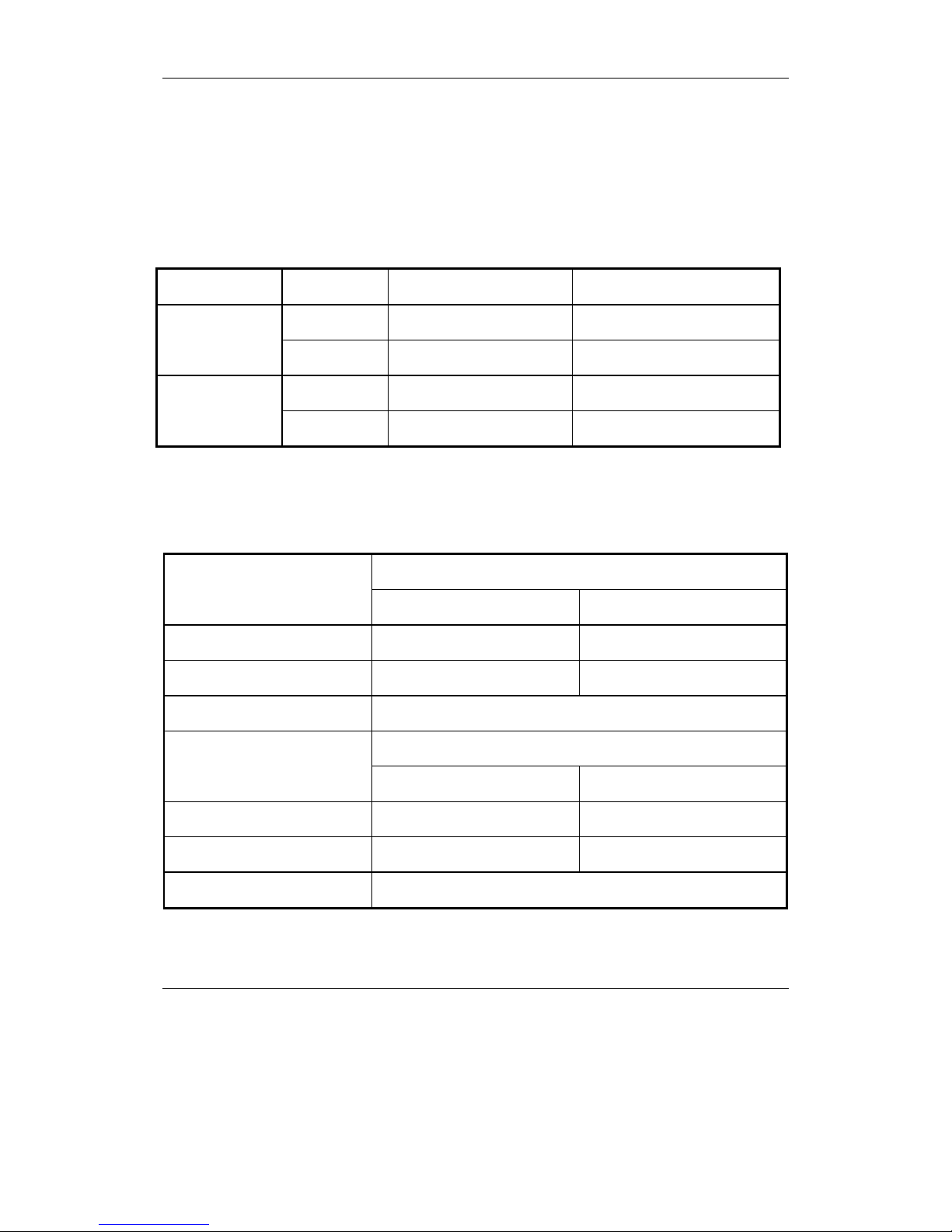
1. Range & Conditions
1.1 Operating Range
Operating Modes Temperature Indoor Temperature Outdoor Temperature
Max.
32℃ DB/23℃ WB 43℃ DB
Cooling
Min.
21℃ DB/15℃ WB 21℃ DB
Max.
27℃ DB 24℃ DB/18℃ WB
Heating
Min.
5℃ DB -7℃ DB/-8℃ WB
1.2 Operating Conditions
Rated Operating Conditions
Indoor Temperature Outdoor Temperature
Cooling
27℃ DB/19℃ WB 35℃ DB/24℃ WB
Heating
20℃ 7℃ DB/6℃ WB
Tubing Length (m) 4.0
Max. Operating Value
Indoor Temperature Outdoor Temperature
Cooling
32℃ DB/23℃ WB 43℃ DB
Heating
27℃ 24℃ DB/18℃ WB
Tubing Length (m) 4.0
DB: Dry-bulb temperature
WB: Wet-bulb temperature
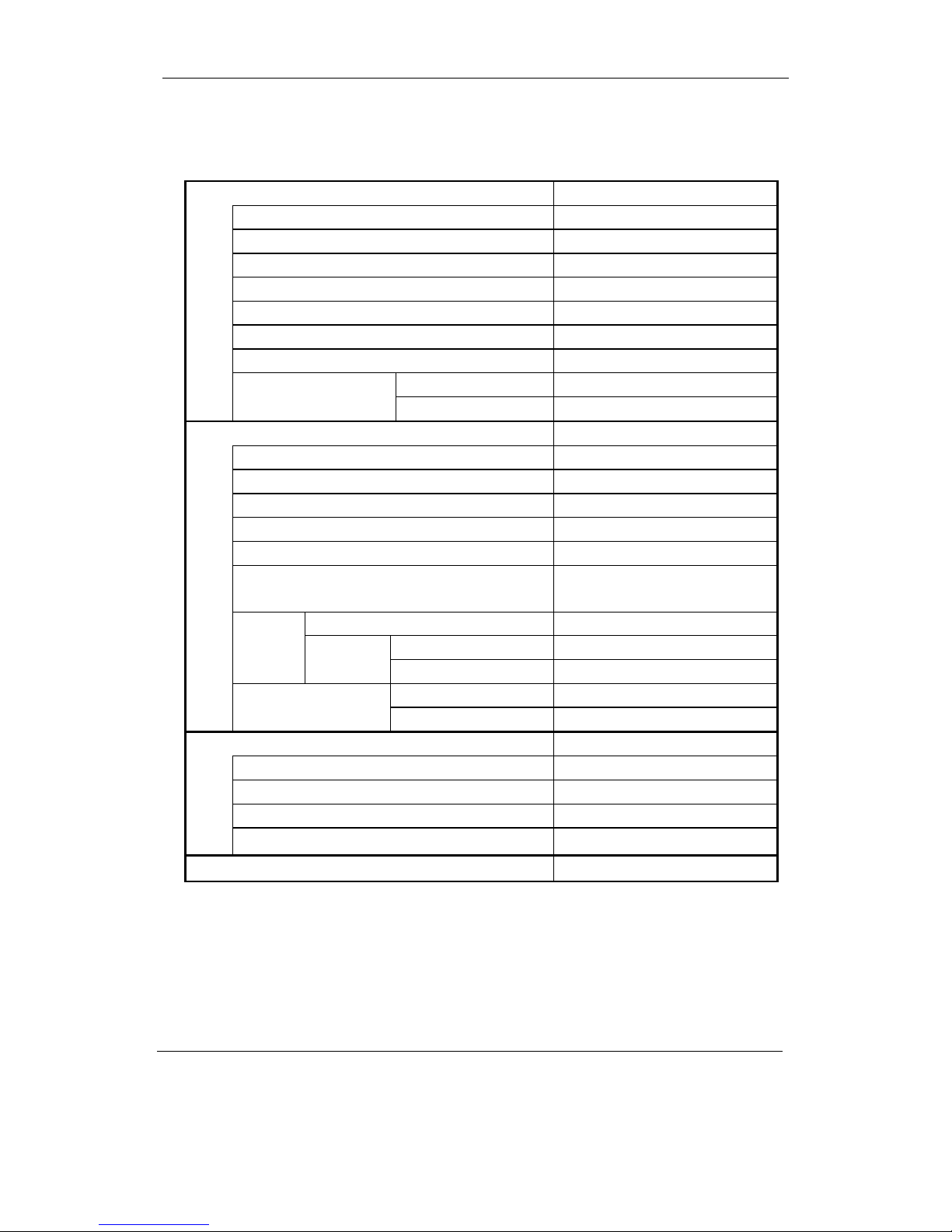
Type
Cooling kW
Heating kW
Cooling kW
Heating kW
kW
COOL
HEAT
Ph-V-Hz
I.U. ~ O.U.
A
A
A
A
n°
Liquid side mm(inch)
Gas side mm(inch)
m
m
Kg
m
g/m
°C
°C
Dimension (W*H*D) mm 918 291 180 918 291 180
Packing (W*H*D) mm 977 357 252 977 357 252
Net/Gross weight Kg
dB(A) 37 35 33 40 38 36
dB(A) 29 27 25 32 30 28
Litres/h
m3/h 430 - - 500 - -
n°
Pa
mm
mm
type
Dimension (W*H*D) mm 786 530 305 786 530 305
Packing (W*H*D) mm 925 617 380 925 617 380
Net/Gross weight Kg
dB(A)
dB(A)
m3/h
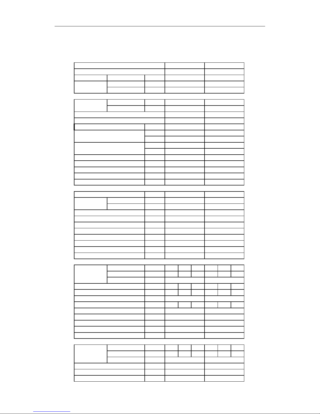
Indoor Unit Model
Outdoor Unit Model
Capacity
Input
EER
COP
Annual Consumption (500h/Y)
ENERGY CLASS
Power supply
Current (Cooling)
Current (Heating)
Max. current
Starting current
Wiring cables i.u./o.u. (without ground)
Refrigerant
Refrigerant Pipe
Splitting distance indoor/outdoor
Splitting level difference (out.-ind./ind.-out.)
Refrigerant Precharge
MAX Splitting with Refrigerant Precharge
Additional Refrigerant Charge
Refrigerant Control
Temperature range cooling
Temperature range heating
Indoor unit
Indoor Noise level 1 m (Hi/Mi/Lo)
Indoor Noise level 2,5 m (Hi/Mi/Lo)
Moisture Removal
Indoor air flow (Hi/Mi/Lo)
Fan Speeds
Available static pressure
MAX Drain up (from the bottom of the I.U.)
Drain hose diameter
Remote Controller (st. equipment)
Outdoor unit
Outdoor Noise level 1 m (MAX)
Outdoor Noise level 2,5 m (MAX)
Outdoor Air flow
HKEJ 261 G
HCNJ 261 G
Constant speed
2,60
2,70
0,78
0,73
3,33
3,70
390
A
A
1-220~240V-50HZ
I.U.
4,23
4,22
-
-
4
R410A
6.35(1/4’)
9.52(3/8’)
10
5/5
0,80
5
15
Capillary
+18°C ~ +43°C
-7°C ~ +24°C
11/13,5
1,1
3
-
-
16
Wireless IR
33/37
51
43
1400
HKEJ 351 G
HCNJ 351 G
Constant speed
3,60
4,00
1,12
1,15
3,21
3,48
560
A
B
1-220~240V-50HZ
I.U.
5,31
5,49
-
-
4
R410A
6.35(1/4’)
12.70(1/2’)
10
5/5
1,00
5
15
Capillary
+18°C ~ +43°C
-7°C ~ +24°C
11/13,5
1,5
3
-
-
16
Wireless IR
36/39
54
46
1600
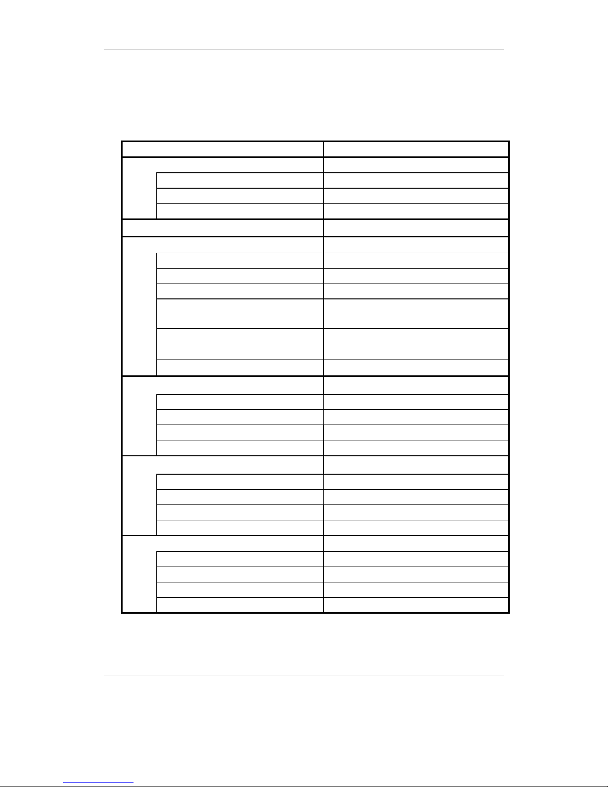
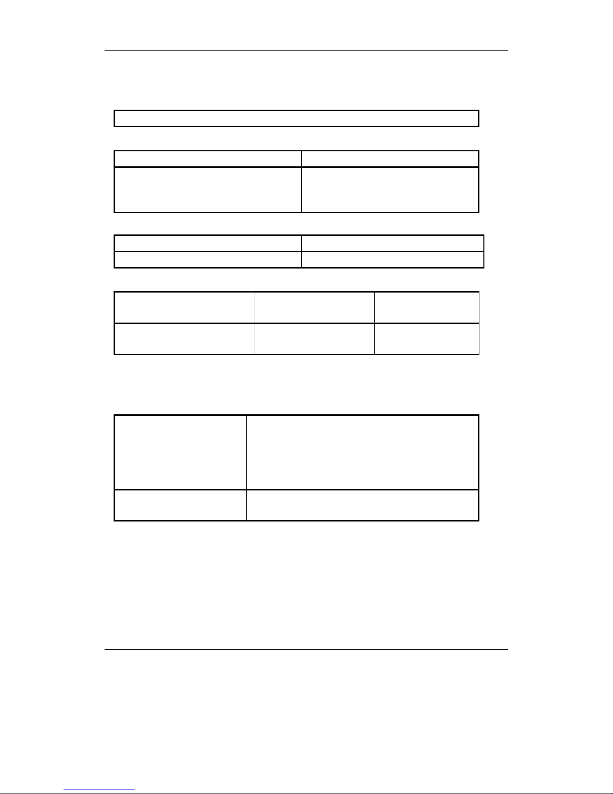
2.2 Specifications of main parts
2.2.1 Indoor unit
Controller
Part No. JUK6.672.512/507/508
Controller Microprocessor
Fuse 250V a.c. / 3.15A/15
Remote controller
KK10A
& Fan motor
Type Cross-flow fan
Quantity / Diameter / Length mm
1/ф86/ 720.5
Fan motor model Wolong: YYW16-4-561
Pole / Rotation of motor
(rpm, 220V High speed)
----
Coil resistance
Ambient temp 20℃ Ω
Wolong: Red-purple: 267.2
purple-White: 494
Fan
Operating capacitor
1μF / 450 VAC
Louver motor
Type Step motor
Model 24BYJ48-FII
Rated voltage (d.c.) V 12
Coil resistance (Ambient temp 25℃) Ω 300Ω±7%
Front panel motor
Type Step motor
Model 35BYJ412B-26
Rated voltage (d.c.) V 12
Coil resistance (Ambient temp 25℃) Ω 200Ω±7%
Heat exchanger
Fin Aluminum fin / Copper tube
Rows 2
Fin pitch mm 1.4
Face area m
2
0.182
Data subject to change without notice
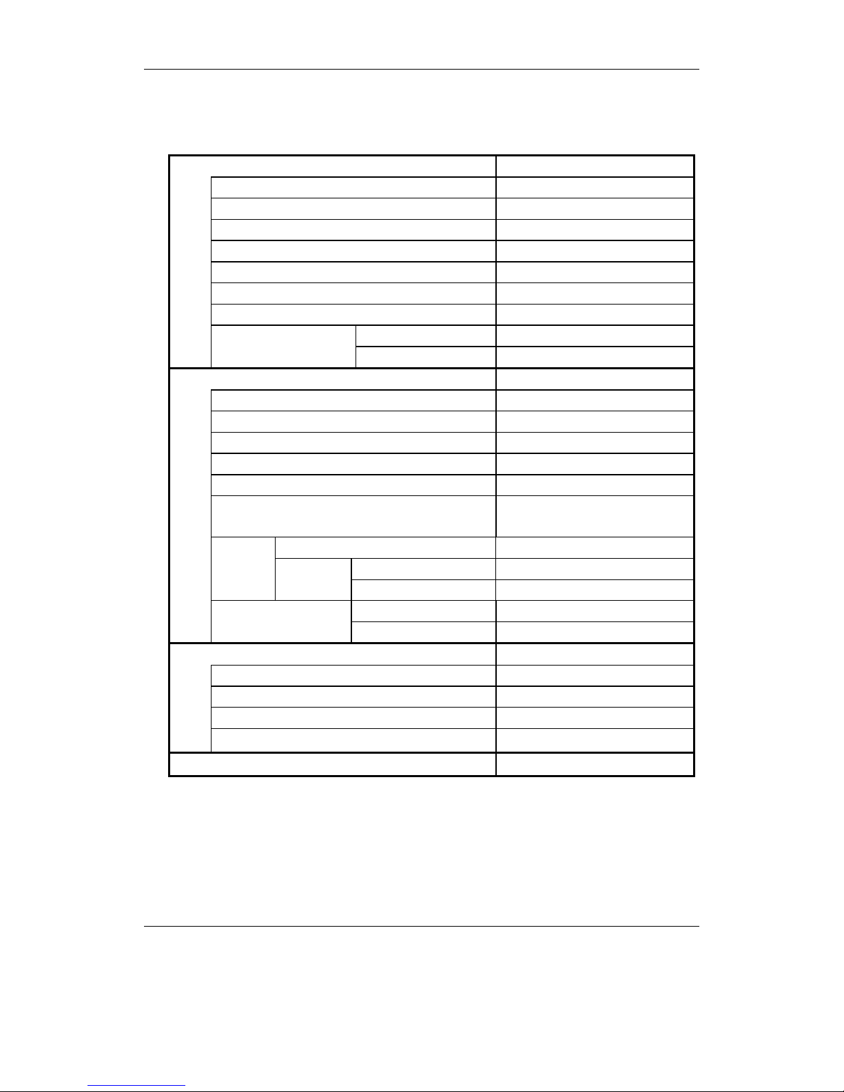
Compressor
Type Rotary(Hermetic)
Compressor model Huarun: C-1RV113H1A
Compressor power input W 800
Compressor oil / Amount CC PVE(FV-68S)/ 350
Overload protector (external) B165-145-241E
Compressor locked rotor amperes A 21.5
Coil resistance (Ambient temp 20℃) Ω
C-R: 3.650 C-S: 5.380
μF
25
Operating capacitor
VAC 450
Fan & Fan motor
Type Propeller fan
Amount / Diameter mm
1/ф400
Fan motor model Welling:YDK17-6G
Pole / Rotation of motor (220V,High speed) rpm 6…720
Rated power output W 20
Coil resistance (Ambient temp 20℃) Ω
White – Gray: 426
Brown–White:214
Type Internal protector
Open ℃ 130±8
Safety
device
Operating
temp
Close ℃ 90±15
μF
2.5
Operating capacitor
VAC 450
Heat exchanger
Fin Aluminum fin / Copper tube
Rows 1.5
Fin pitch mm 1.4
Face area m2 0.375
External coating
Powder-spraying coating
Data subject to change without notice
Compressor
Type Rotary(Hermetic)
Compressor model Huarun: C-RV146H1AB
Compressor power input W 1000
Compressor oil / Amount CC PVE(FV-68S)/ 500
Overload protector (external) B230-150-241E
Compressor locked rotor amperes A 28
Coil resistance (Ambient temp 20℃) Ω
C-R: 2.355 C-S: 5.600
μF
25
Operating capacitor
VAC 450
Fan & Fan motor
Type Propeller fan
Amount / Diameter mm
1/ф400
Fan motor model Welling:YDK40-6H
Pole / Rotation of motor (220V,High speed) rpm 6…880
Rated power output W 40
Coil resistance (Ambient temp 20℃) Ω
White – Gray: 211
Brown–White: 258
Type Internal protector
Open ℃ 130±8
Safety
device
Operating
temp
Close ℃ 90±15
μF
2.5
Operating capacitor
VAC 450
Heat exchanger
Fin Aluminum fin / Copper tube
Rows 2
Fin pitch mm 1.4
Face area m2 0.375
External coating
Powder-spraying coating
Data subject to change without notice
2.3 Specifications of other parts
Indoor unit
Transformer (TR)
DB-08-05B
Thermal resistor
KTM-41-C9(Copper), KTEC-41-C12(Plastic)
Resistance( KΩ)
0℃ 32.97KΩ 10℃ 20.00KΩ
20℃ 12.51KΩ 25℃ 10.00KΩ
30℃ 8.048KΩ
Power relay (PR)
G4A-1A-E 12VDC Or
JQX-102F-012
JZC-43F-012-HS
Coil rated voltage
Coil resistance Ω(20℃)
12V d.c
Ω
12V d.c
Ω
Outdoor unit
Four-way reversing valve
Coil rated value
Coil resistance Ω(20℃)
AC 220V/240 50Hz 6W
1450±10%
Data subject to change without notice
Power supply
JUK6.604.1743
16A/ 250Va.c

3. Control Specifications
3.1 System source
3.1.1 Signal input
Temperature sensor signal (indoor temperature, indoor coiled temperature, outdoor coiled
temperature); remote control signal; emergency switch input; auto diagnosis/ time-shortening input; fan
speed (high/medium/low/breeze) input; (capacity, heating or cooling) input; AC zero p assage;PG feedback.
3.1.2 Signal output
Display signals (SI, SCK, RCK); louver motor (1a, 1b, 1c, 1d); step motor(2a, 2b, 2c, 2d); anion/
Electronic dust collector; ultraviolet,Auxiliary electric heating; PG output; buzzer & buzzer power;
compressor; outdoor fan motor; 4-way reversing valve.
3.2 Control functions
3.2.1 Switches input:
Press on / off button when the air conditioner is in the off mode. The unit turns on and works at 24℃
in AUTO mode automatically. Press this button when the unit is running or in TEST RUN mode, air
conditioner is turned off.
Press the button for four seconds until the buzzer beeps twice. Air conditioner enters the TEST RUN
mode. During the period of test run, the air conditioner is controlled by remote controller. The air conditioner
will start the normal operation automatically if the test running time is for more than 15minutes. Air
conditioner will be stopped and exit the test running mode when users press on / off button which is on the
indoor unit or on the remote controller.
3.2.2 Timing on/off and program control
3.2.2.1 Turn on the air conditioner on timer
The air conditioner will start operation at the set time. “Timing on” function is only effective for one
time in 24 hours. If user turns on the air conditioner by pressing ON/OFF button on the remote controller
before the set time, then “Timing on” function will be cancelled. If user select “Timing on” when the air
conditioner is in on status, the unit will be turned off and it will be turned on at the set time. The original
display of “Timing on” is 12:00.
3.2.2.2 Turn off the air conditioner off timer
The air conditioner will exit running at the set time. “Timing off ” function is only effective for one time
in 24 hours. If user selects “Timing off” function when the air conditioner is in the off status, the unit will be
turned on and it will be turned off at the set time. If user turns off the air conditioner by hand before the set
time, then “Timing off” function will be cancelled. The original display of “Timing off” is 12:00.
3.2.2.3 Program control
The air conditioner will be turned on/off at the set time everyday. If user turns off the air conditioner
by hand before the set time, then “Timing off” function will be cancelled; but “Timing on” function is still
effective. If user turns on the air conditioner by hand before the set time, then “Timing on” function will be
cancelled; but “Timing off” function is still effective.

3.2.3 Temperature control:
There is 3℃ temperature comprehension in HEAT mode. Not available for COOL, AUTO or DRY
modes.
3.2.4 Sleep mode:
Temperature will be adjusted automatically when the sleep mode is set. The set temperature will
increase 1℃ after running 1 hour in Cooling or dehumidifying mode. Temperature will decrease 1℃ after
running 1 hour in heating mode. The set temperature will be controlled between 16℃ and 32℃.
When the air conditioner runs in sleep mode, the Max. indoor fan speed is set at medium level.
Indoor fan motor will stop running after stopping the compressor for 30 seconds. (In cool mode, indoor fan
motor will not stop).
3.2.5 The front panel
The front panel will be opened either the air conditioner is started running or air refres h function is
started; or it will be closed.
Indoor fan motor will be started running only the front panel is opened completely.
3.3 Operating mode
3.3.1 Auto-operating mode: (not available for cooling-only type air conditioner)
When air conditioner stars running or the set temperature is adjusted under this mode, Master
controller can select running mode (cooling or heating) automatically by the D-value between indoor
temperature and set temperature. It runs in cooling mode when Tr≥Ts (Tr: Room temperature, Ts: Set
temperature) and in heating mode when Tr<Ts.
In heating mode, When Tr≥Ts+3℃ lasts for 15 minutes. It turns into cooling mode.
In cooling mode, when Tr≤Ts-2℃ lasts for 15 minutes. It turns into heating mode.
When Ts-2℃< Tr < Ts+3℃, it keeps original operating mode.
Temperature control range: 16℃-32℃; Original value: 24℃;
Temperature control precision: ±1℃;
3.3.2.Cooling:
Temperature control range: 16℃-32℃; Original value: 24℃;
Temperature control precision: ±1℃;
Characters on control:
4-way reversing valve closes:
When Tr≥Ts+1℃, compressor runs; When Tr≤Ts-1℃, compressor stops; The control circuit will
stop compressor only after it has run at least 5 minutes. The compressor can be restarted 3 minutes later
the turn-off.
Fan speed control:
Auto: When Tr>Ts+2℃, high speed;
When T s+1℃≤Tr<T s+2℃, medium speed;
When Tr< Ts+1℃, low speed.
Manual: Users can select the fan speed of high, medium or low level as n e eded when the air conditioner is
1
2
3
5
4
Fig.1
6

in the turn-on status.
Louver adjustment:
Manual (vertical direction): Set the blades position as needed. (Position 1-6 in figure 1.)
Auto (vertical direction): The range of sweeping is in position 2-5.
3.3.3. Dehumidification:
Temperature control range: 16℃-32℃; Temperature control precision: ±1℃;
Characters on control:
4-way reversing valve closes.
When Tr≥Ts+2℃,the running mode is the same to the cooling operation;
When Ts-1℃< Tr < Ts+2℃, compressor and outdoor fan motor run continuously. And indoor fan
motor runs at low fan speed
When 15℃< Tr < Ts-1℃, compressor and outdoor fan motor are working according to 3 minutes
working alternating with 9 minutes stopping. Indoor fan motor runs at low fan speed when compressor is
running, and it runs at breeze level for 30 seconds later the turn-off of compressor. 30 seconds later, fan
motor will turn off.
When Tr≤15℃, indoor and outdoor fan motor will stop running, louver blades (vertical direction)
can’t be controlled.
Louver adjustment (vertical direction): The range of sweeping is in position 2-5.
3.3.4. Heating (not available for cooling-only type air conditioner)
Temperature control range: 16℃-32℃; Original value: 24℃;
Temperature control precision: ±1℃;
Characters on control:
4-way reversing valve opens.
When Tr≤Ts-1℃, compressor, 4-way reversing valve and outdoor fan motor all open.
When Tr≥Ts+1℃, compressor and outdoor fan motor both close; Indoor fan motor is running at
breeze. When Trc (Trc: The indoor coiled temperature) <F℃ , the air conditioner will enter into
cool-airflow-prevention operation, the PAUSE indicator will light.
Indoor Fan motor control:
Manual: Users can select the fan speed of high, medium or low level as needed.
Auto: When Tr< Ts-2℃, high speed; When Tr≥Ts-2℃,medium speed;
Louver adjustment:
Manual (vertical direction): Set the blades position as needed. (Position 1-6 in figure 1.)
Auto (vertical direction): The range of sweeping is in position 1-4.
Compressor control:
The control circuit will stop compressor only after it has run at least 5 minutes. Compressor can be
restarted 5 minutes later the turn-off.
3.3.5. Sweep Mode
In sweep mode, compressor, 4-way reversing valve and outdoor fan motor are all stops;
Indoor fan motor can be adjusted at high, medium low speed and breeze.

Louver adjustment:
Manual: Users can set the position as needed. (Positions 1-6 in figure 1)
Auto: The range of sweeping is in position 1-5.
3.4 Protection function
3.4.1 Delay-starting protection for the compressor
Compress will restart working 3 minutes(5 minutes in HEAT mode) later the turn-of f of compressor or
power-off to keep the pressure balance of the cooling system.
3.4.2 Freeze-prevention: To prevent indoor heat exchanger freezing in COOL and DRY
operation.
When Trc≤3℃ for 2 minutes, the air conditioner will enter into freeze-prevention operation. If
indoor fan speed is at low or breeze level, it will turn to medium speed automatically; if indoor fan speed is
at medium speed, it will turn to high speed;, The air conditioner will exit Freeze-prevention op eration when
Trc>8℃, indoor fan motor runs at the set fan speed. Compressor will stop running when it runs at least 10
minutes and Trc≤-2℃. If the off-time of compressor is for more than 6 minutes or Trc≥8℃, and the
compressor stops running for more than 3 minutes. Compressor and outdoor fan motor will restart working.
The air conditioner will exit Freeze-prevention operation, and indoor fan motor is running at the set speed.
3.4.3 Cooling overload working: To prevent the temperature of indoor heat
exchanger is too high (not available for cooling-only type air conditioner)
When Toc≥60℃, the air conditioner will enters into cooling overload protection, and indoor fan
speed will drop a gear. When Toc≥75℃, compressor will stop, indoor fan motor goes on running. When
Toc≤55℃ and the time of indoor fan exchange is for more than 5 minutes, the air c onditioner will exit
cooling overload protection; indoor fan motor and compressor will restore normal operation.(compressor
has a delay protection function)
3.4.4 Cool-airflow-prevention: (not available for cooling-only type air conditioner)
In heating operation, if Trc<F℃, and the running time of compressor is for less than 5 minutes, air
conditioner stays in the cool-airflow prevention, Louver blades will move to position 6 and can’t be
controlled; Indoor fan motor will stop and PAUSE (red) indicator will light.
3.4.5 Heating overload working: (not available for cooling-only type air conditioner)
When Trc≥A℃, the unit enters into heating overload protection. If indoor fan speed is set at lo w or
breeze level, it will turn to medium speed automatically; if indoor fan speed is set at medium speed, it will
turn to high speed; When Trc≥B℃, outdoor fan motor stops. When Trc≤D℃, outdoor fan motor will restart
working. Air conditioner will exit overload protection when Trc drops blow E℃, compressor restarts working,
Indoor fan motor runs at the set fan speed.
When Trc≥C℃and the build-up time of compressor running is for more than 5 minutes, compressor
will be stopped.

3.4.6 Defrosting: (not available for cooling-only type air conditioner)
3.4.6.1 Defrost entry conditions
After the compressor running for more than 10 minutes.
A. Indoor unit enters into overload prevention and outdoor unit stops. When outdoor fan motor runs for more
than 10 minutes, and the build-up time of compressor running is for more than 50 minutes, Trc≤A-1℃
and Toc≤-2℃( Toc: The outdoor coil temperature.)
B. Not overload, but Toc≤-17℃ for 30 seconds. The build- up time of compressor runnin g is for more than
25 minutes.
C. The build-up time of compressor running is for more than 3 hours. And Toc≤-2℃ for 5 minutes. Trc≤
G-2℃ and Trc≤(Tr+H)℃.
D. The build-up time of compressor running is for more than 3 / 2 hours. And it reaches the condition of the
unit stopping. Toc drops blow -2℃ for 3 minutes(overload).or Toc≤ -2℃ and Trc≤G+2℃ (not
overload).
E. The build-up time of compressor running is for more than 50minutes.Toc ≤-2℃, Trc drops at least 3℃
and Trc≤G℃, Trc≤(Tr+H) ℃.
F. Toc ≤-2℃, the temperature decreases 1℃ every 6 minutes (repeat for 3 times). The build-up running
time is for more than 25 minutes.
The air conditioner will defrost only one of the conditions is meet.
3.4.6.2 Defrosting:
Compressor, indoor and outdoor fan motor will stop working after the unit entering into defrost running.
55 seconds later, 4-way reversing valve will close. Another 5 seconds, compressor starts running. When the
time of the compressor running is for more than 10 minutes or Toc≥20℃, and defrosting time is for more
than 3 minutes, Compressor stops. 55 seconds later, 4-way reversing valve will open. Another 5 seconds
later, compressor and outdoor fan motor will restart working and exit defrosting operation. In defrosting
operation, the time of compressor running is at least 3 minutes. Cool-airflow-prevention and blow ing residue
heat are both efficient.
3.4.7 Testing codes
code 1: to set test run; code 2: to set fast testing;
code 3: to set auto-diagnosis; code 4: to cancel the above setting;
3.4.8 Temperature and failure code display
The defining of code refers to the following:
Code 11: room temperature code 12: indoor coil pipe temperature
Code 13: outdoor coil pipe temperature code 14: abnormal information
E0: Normal operation P1: Cooling overload
P2: Heating overload F4: PG motor is abnormal
F1: The circuit of room temperature sensor is damaged or abnormal
F2: The circuit of indoor coiled temperature sensor is damaged or abnormal
F3: The circuit of outdoor coiled temperature sensor is damaged or abnormal
When temperature sensor or PG motor is damaged or abnormal, RUN indicator will flash.

3.5 Other functions
3.5.1 Auto-diagnosis
Test terminal on the main panel is shorted. The Auto-diagnosis functions are in the following steps
when the power is turned on.
Buzzer beeps 1s →Runni ng indicator on 0.5s →Pause indicator on 0.5 s → Timer indicator on
0.5s →air refresh indicator on 0.5s →breeze indicator on 0.5s→low fan speed indicator on 0.5s →medium
fan speed indicator on 0.5s →high fan speed indicator on 0.5s →air refres h indicator on 0.5s →ultraviolet
indicator on 0.5s →auxiliar y electric heating indicator on 0.5s →step motor for louver(1a,1b,1c,1d)on 0.5s
→step motor for front panel(2a,2b,2c,2d)on 0.5s→ 4-way reversing valve 0.5s→Outdoor fan motor run
0.5s → compressor run 0.5s→ no output for 0.5s→ all signal output for 1s→ Buzzer beeps 1s
During the period of auto-diagnosis, LED display “11,22,33,44,55,66,77,88,99,00” circularly, and
each display for 0.5s. Indoor fan motor runs at medium fan speed.
During the period of auto-diagnosis, buzzer will keep beep if temperature sensor is abnormal.
3.5.2 Timer saving:
The time-shortening terminal on the main panel is shorted when the unit is powered on. The buzzer
beeps twice and the master controller CPU run as 61 times as the former speed.
3.5.3 Auxiliary electric heating: (not available for cooling-only type air conditioner)
The starting conditions of auxiliary electric heating:
A. Received the signal for remote controller to start this function;
B. Air conditioner runs in heat mode;
C. Compressor runs for more than 1 minute.
D. Tr≤14℃.
E. Ts-Tr≥6℃
F. Indoor fan runs at high or medium fan speed.
Auxiliary electric heating will be closed under the one of the following conditions.
A. Tr≥18℃;
B. Ts-Tr≤2℃;
C. Trc≥A-2℃;
D. Indoor fan runs at low or breeze fan speed;
E. Defrost operation;
F. Received the signal for remote controller to stop this function;
3.5.4 LCD display
The LCD doesn’t display symbols if air conditioner is in off status. Timer indicator will light if ON
TIMER function set before. The LCD will display the set temperature and running mode when air
conditioner is running but air refresh doesn’t functioned. And it will display index of air refresh when air
conditioner and air refresh are running. The index will display “6” if air refresh runs for more than 50 minutes;
“7” for 2 hours running; “8” for 3 hours running; and “9” for 4 hours running. T his index range is 1~9. if set
temperature is changed during the period of air refresh, the LCD will display the set temperature for 1
minutes, and then return to display the index of air refresh. LCD will not display the index if air refresh
function is stopped running. Only run indicator lights If SLEEP function is set for 30 seconds later; and it will
display all setting if remote control signal is received.
3.5.5 Air refresh function
Press air refresh button when the unit doesn’t run, air refresh and run indicators will light (display the
index of air refresh), air conditioner will be turned on and runs at the set fan speed; in ion mode, anio n are
working according to 10 minutes working alternating with 5 minutes stopping. When air refresh function is
turned off, the unit will turn back to the original mode. Press air refresh button if Air conditioner is runnin g,
air refresh will be functioned and the indicator will light too.
3.5.6 Quiet Operation
Press quiet button when air conditioner is in SWEEP mode, the indoor fan will run at breeze;
Press air refresh button if air conditioner doesn’t run, the indoor fan will run at breeze if the setting fan
speed is breeze.
Quiet function is not effective for other status.
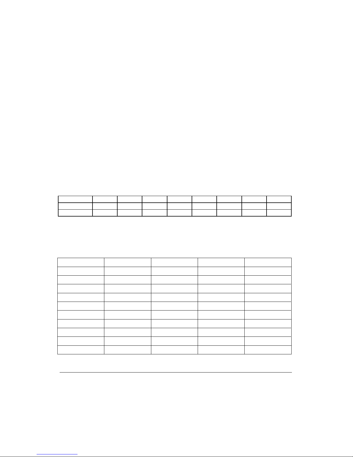
3.6 Parameter table
Temperature table of protecting point
The type of remote controller for heat-pump air conditioner is KK10A.
The type of remote controller for cooling-only air conditioner is KK9B.
Fan motor rotation
Voltage High fan speed Medium fan speed Low fan speed Breeze
0.5 1080 980 880 760
1.0 1110 1010 910 770
1.5 1140 1040 940 780
2.0 1170 1070 970 790
2.5 1200 1100 1000 800
3.0 1230 1130 1030 810
3.5 1260 1160 1060 820
4.0 1290 1190 1090 830
4.5 1320 1220 1120 840
5.0 1350 1250 1150 850
Model
A
B C D E F G H
HKEJ 261 G 49 52 65 44 42 32 39 22
HKEJ 351 G 54 57 70 48 46 34 43 26
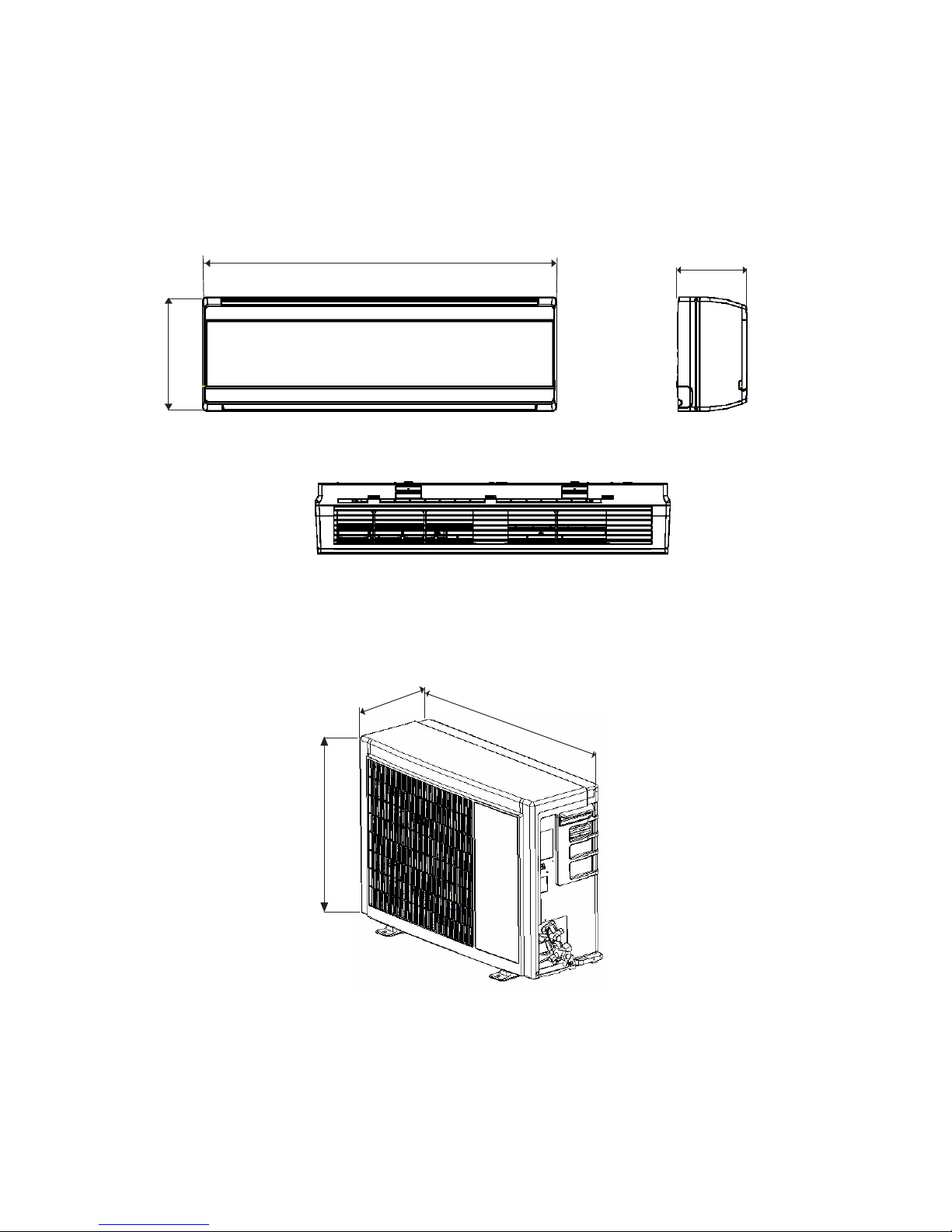
4. Dimensional data
Indoor Unit
Outdoor Unit
918
291
180
786
305
530
Unit: mm
The above figures are only schematic, and they may be slightly different from
the actual appliance you bought.
Monosplit ON/OFF models:
HCNJ 261 G, 351 G
Outdoor Unit
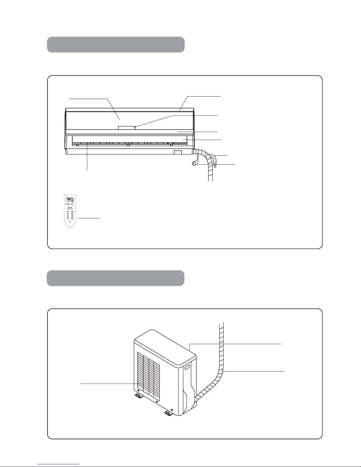
OUTLINE OF PARTS AND FUNCTIONS
Indoor Unit
Monosplit ON/OFF models:
HKEJ 261 G, 351 G
NOTE: The figure above is for explanation purpose only; the actual appliance may be slightly different.
NOTE: The figure above is for explanation purpose only; the actual appliance may be slightly different.
Power cord
Condensate drain hose
Motorized horizontal flap
Remote controller receiver and Display
Air inlet
Vertical louvers
(manual adjusting)
Front panel
Decorated board (removable)
Infrared remote controller
Refrigerant piping
and electrical wiring
Air inlet
(sideways and rear)
Air outlet

LED display panel on the Indoor Unit
OUTLINE OF PARTS AND FUNCTIONS
Monosplit ON/OFF models:
HKEJ 261 G, 351 G
Front panel
Air filter
Decorated board
Motorized flap
(for vertical distribution)
Manual louvers
(for horizontal distribution)
"PAUSE" Indicator
"RUN" Indicator
It lights up to indicate that the
unit is operating:
AUTO (Automatic)
HEAT (Heating)
COOL (Cooling)
SWEEP (Fan only)
DRY (Dehumidifying).
It lights up during automatic
defrosting, or when the preheating function for the indoor
heat exchanger is active (i.e.
when operation in Heating
mode starts).
ON/OFF Switch
For emergency operation in AUTO mode (if
the remote controller
is not available). Press
it again to stop the
unit.
"TIMER" Indicator
It lights up to indicate
that the unit's operation
has been programmed
by the Timer.
"AIR REFRESH" Indicator
It refers to a function which
is unavailable on these models.
Set temperature display
The desired temperature value is
displayed, as set by the User
through the infrared remote
controller.
Current indoor fan speed setting indicator
Indoor fan is set at "HIGH" speed
Indoor fan is set at "MEDIUM" speed
Indoor fan is set at "LOW" speed
NOTES:
If the current indoor fan speed setting indicator is flashing, this means that
"AUTO" fan speed has been selected.
1. Do not put fingers or sticks into the air inlet or air outlet of the indoor unit.
2. Touching the indoor fan which rotates at high speed, may result in serious injuries. Moreover the
aluminium fins on the heat echanger are sharp-edged. As a consequence, particular attention must
be observed when the front panel of the indoor unit has been opened for maintenance or air filters
cleaning. It is strongly adviced to switch off the main power line and wait some minutes before
carrying on the inspection work.
3. If the "RUN" indicator flashes, this means that a malfunction has occurred. In such cases, it is
required to contact a Service Agent.


NO. NAME CODE
1 Pressure plate for tube
2 Electrical motor lid
3 Fan electromotor
4 Flap motor
5 Flap
6 Crank shaft
7 Connecting bar
8 Media frame
9 Electric control assembly
10 Electric control cover
11 Air filter (right side)
12 Front panel assembly
13 Display window assembly
14 Decorative slat
15 Air filter (left side)
16
NM-potocatalyst deodorant
net
17 Cover for step motor
18 Step motor
19 Air guiding frame assembly
20 Axile bush
21 Fan
22 Supporter (left side)
23 Evaporator assembly
24 Real panel assembly
25 Installation board
26
27
28


6. Refrigerant Flow Diagram
Thermal insulating of refrigerant pipeline
To prevent heat loss and condensed water from dropping on the floor, the wide and narrow tube of
air conditioner should be wrapped with thermal insulating materials. For using capillary tube, and the
tubes are in low temperature, the thickness of thermal insulating materials shall be more than 8 mm.
Narrow tube
Ф6.35 mm(1/4”)
Ф9.52 mm(3/8”)
Wide tube
Ф12.7 mm(1/2”)

7. Circuit Diagram
7.1 Electrical wiring diagram for outdoor unit
To avoid electrical shock hazard, be sure to disconnect power before
checking, servicing and/or cleaning any electrical parts.
Warning

7.2 Electrical wiring diagram for indoor unit
To avoid electrical shock hazard, be sure to disconnect power before
checking, servicing and/or cleaning any electrical parts.
Warning

7.3 Electrical Schematic wiring diagram

8. Troubleshooting
8.1 Check before troubleshooting
8.1.1 Check power line
To check whether the power line is connected correctly to the terminal No 1 which is on the
terminal block of the indoor unit
8.1.2 Check unit wiring
To check whether the inter-unit wires are connected correctly in accordance with the wiring
diagram.
8.1.3 Check power supply
To check whether the power supply is in the specified range (220±10%).
To check whether the power supply is being supplied.
8.1.4 Check connector and lead wire of indoor and outdoor units.
To check whether the insulating cover of the lead wire is damaged.
To check whether the lead wire and the connector are connected well
High-voltage will result in electric shock or death.
Always cut off the power before checking and maintaining.
Warning:

To check wires.
8.1.5 Poor cooling or heating phenomena.
Poor cooling
(heating)
performance
Is the temperature
set properly?
Change the set temperature.
The heating (cooling)
load is too large.
Reduce heat (cool) source or change
the air conditioner with large power.
Refrigerant
flow is not
enough
Refrigerant is not enough.
Filling it
Capillary tube is blocked.
Replace it.
Compressor is in error.
Replace it.
Service valve is not open
completely.
Open it
completely.
Air circulating
capacity is
not enough.
The air filter is blocked.
Clean it.
4-way reversing valve fails.
Replace it
Fan running speed
is at “low”.
Change it to “high’ or
“medium”.
Connection between indoor
and outdoor units is in poor
thermal-insulated.
Wide and narrow tubes
are thermal-insulated
separately.
Cooling air -flow
4-way reversing valve is defective.
Replace it
Cooling airflow
protector is no use.
The pause indicator is on.
Replace the electric
controller of indoor unit.
Temperature sensor of
indoor coil is defective.
Replace the sensor.
No
Yes

8.1.6 Compressor does not run.
8.1.7 Only outdoor fan motor does not run.
8.2 Electrical Troubleshooting
8.2.1 Check before or after repairing the units.
8.2.1.1 Check whether the connection of the units is in good condition.
8.2.1.2 Check whether the connection of the units is in good condition.
8.2.1.3 Check whether the lead wire and connector of the units are in good condition.
8.2.1.4 Check power circuit.
8.2.2 The air conditioner do not run
8.2.2.1 Check the switch power.
① Without 30V DC output from two ends of the capacitor C405 (the indicator does not light).
A. Check 240V power supply, power socket → power cord → fuse(3.15A /220V) → high voltage
capacitor C410 (whether there is 280 ~ 300V DC or not)
B. Check the capacitor C405
Check the relay of the compressor
motor for normality.
Check the winding resistor of the
compressor.
Replace the compressor.
Replace the relay
Yes
Abnormal
Check the fan rotation Check if foreign matter is in
the fan cover.
Check if fan motor is broken
or foreign matter in bearing.
Measure the resistance of motor coil.
Check the capacitor of the fan motor.
Ok
Ok

C. Check the switch transformer for sounding. If the transformer sounds, remove the load on the power
supplies of 30V DC and 12V DG. If still without 30V DC output after removal, then the switch power is
defective. If with 30V DC output, the load is short – circuited but the switch power is good. Then check
the secondary load circuit.
D. Check D 401, D402, C408 and D403 for PWM (66KHz) output.
E. Check VD405 and VD406 for breakdown.
② With voltage output (much different from 30V DC)from two ends of the capacitor C405 (the indicator
lights).
A. Remove the power load.
B. If without 30V DC output but with stable voltage, check R401 and R403.
8.2.2.2 Power supply is OK.
① Check the power supply connected to D300 (MCU) for normality.
② Check whether the toggle switch (XS310) buzzes when the switch inputs.
③ The sensor gives an alarm.
④ Over-current alarms (check the switch power for correct installation and check the compressor current
detector.)
8.2.3 The indoor fan does not run.
Check the fan for being in protection.
8.2.4 the louver motor does not run or runs improperly.
8.2.4.1 Check the power supply 12V.
8.2.4.2 Check the motor for being in protection.
8.2.4.3 Check the PCB (XS301 and D300) for welding loosely or welding jointly.
8.2.4.4 Replace the step motor.
8.2.5 Sensor alarm, units stop.
8.2.5.1 Check the 5V power supply.
8.2.5.2 Check PCBs for welding loosely.
8.2.5.3 Check the sensor for being damaged.
8.2.6 The outdoor compressor, fan and four-way valve do not run.
8.2.6.1 Check input and output of relay K301 for fan. Check input and output of relay K302 for four-way
valve.
8.2.6.2 Check input and output of relay K303 for compressor.
8.2.6.3 Check 12V power supply.
8.2.6.4 Check the connection wiring.
8.2.6.5 Check the relay and start - up capacitor.
8.2.6.6 Check whether the compressor, fan and four – way valve are in good condition.
8.2.7 No signal, indicators does not light.
8.2.7.1 Check the remote control for being damaged or the batteries for being exhausted.
8.2.7.2 check for obstacles between the unit and remote controller.
8.2.7.3 Check C305 on the indicator and 5V power supply.

8.2.7.4 Check IC10,D20 and D30 on the indicator.
8.2.7.5 Check the connection wire.
8.2.8 The switch board is defective.
8.2.8.1 Check the toggle switch and 5V power supply.
8.2.8.2 Check the connection wire.
9. Checking Electrical Components
9.1 Measure insulation resistance
The insulation is in good condition if the resistance
exceeds 2 MΩ.
9.1.1 Power supply wires
Clamp the ground pins of the power plug with the lead clip
of the insulation resistance tester and measure the
resistance by placing a probe on either of the power wires.
(Fig. 1)
Then measure the resistance between the
ground wire and the other power wire. (Fig. 1)
9.1.2 Indoor unit
Clamp an aluminum plate fin or copper tube with the lead
clip of the insulation resistance tester and measure the
resistance by placing a probe on each terminal screw on the terminal plate. (Fig. 2)
Note that the ground line terminal should be skipped for the check.
9.1.3 Outdoor unit
Clamp a metallic part of the unit with the lead
clip of the insulation resistance tester and
measure the resistance by placing a probe on each terminal
screw where power supply lines are connected on the
terminal plate. (Fig. 2)

9.1.4 Measurement of Insulation Resistance for Electrical Parts
Disconnect the lead wires of the desired electric part from terminal plate. Capacitor, etc.
Similarly disconnect the connector. Then measure the insulation
resistance. (Fig. 3 and 4)
9.2 Checking continuity of fuse on PCB ass”y
Remove the PCB ass’ y from the electrical component box. Then
pull out the fuse from the PCB ass’ y. (Fig. 5)
Check for continuity using a multimeter as shown in Fig. 6
9.3 Checking motor capacitor
Remove the lead wires from the capacitor terminals, and then
place a probe on the capacitor terminals as shown in Fig. 7.
Observe the deflection of the pointer setting the resistance
measuring range of the multimeter to the maximum value.
The capacitor is “good” if the pointer bounces to a great extent
and then gradually returns to its original position.
The range of deflection and deflection time differ according to
the capacity of the capacitor.
Refer to electric wiring diagram.
If the probe can’ t enter the p oles because
the hole is too narrow then use a probe with
a thinner pin.
Note:

INSTALLATION INSTRUCTION FOR SPLIT TYPE AIR CONDITIONER
Model: HKEJ- HCNJ 261 G - HKEJ - HCNJ 351 G
INSTALLATION GUIDE
• This air conditioner needs standard safety and operation promulgated by the Nation.
• You need to invite professional air conditioner service and maintenance personnel to
install or remove the air conditioner. Problems may occur and you may suffer losses if
non-professional install the air conditioner.
• User shall provide the power that meets installation and operation and requirements.
The voltage for this product is 198-253V~. Voltage exceeding this scope will affect the
normal operation of the air conditioner.
• Separate line that is installed with delay fuse protector or automatic breaker should
be used for the air conditioner.
• The air conditioner must be correctly and reliably grounded, or it may cause electric
shock or fire.
• Do not connect the power of the air conditioner before well connecting and carefully
checking the tubing and wires.
• The appliance shall not be installed in laundry or bathroom.
• The air conditioner can be connected only to a supply with system impedance no
more than 0.35 ohm (0.16 ohm for HKEJ-HCNJ 351 G). If necessary, please consult
your supply authority for system impedance information.
• The instruction is subject to change without notice.
INSTALLATION OF ACCESSORIES
• Examine carefully the attached packing list and check whether the accessories are
complete.
• Users may need to buy at their own expenses the articles not included in the packing
list and may be needed in installing.
10. Installation


Fig.12
CONNECTION OF WIRES
1. Indoor Unit
• Push the decorated board downward and move it away,
open the front panel by pushing it upward.
• Detach the electric control cover and pressure plate of
lead wire.
• Connect the connecting wires of the unit separately to
the corresponding terminals, and fix the terminals (Fig. 13).
• Butt the signal control wire.
• Press tightly the connecting wires of the units with pressure
plate of lead wire.
• Close the connection lid and screw it tightly.
• Close the front panel and reinstall the decorated board.
• For the details, please refer to "How to clean the air
filters" in the "User's Manual".
2. Outdoor Unit
• Loose off the screws and remove the electronic
device lid.
• Dismantle the pressure plate of wire fastener.
• Connect the connecting wires of the unit to the
corresponding terminal, and fix the terminals (Fig. 13).
• Butt the signal control wire.
• Press tightly the connecting wires of the unit with
pressure plate.
• Remount the electronic device lid to the original
position.
• RW type lead wire is used for power cord.
• If User wants to prolong or replace the power wire,
please do it according to the table.
• Ensure that wire connections are carried out according
to the wiring diagram of the air conditioner.
HKEJ 261 G
HKEJ 351 G
Fig.11
Fig.13

TUBE STRAPPING
• Strap with PVC Protective tapes the tubes, discharge pipes, connecting wires.
• Strapping should start from the lower part of the outdoor unit to the tube bundle
wall inlet.
• Fix the PVC protection tapes with plastic adhesive tapes to prevent loosing.
• Fix the tube bundle with tube clamps on the wall.
• Seal the external wall holes with sealing gum or putty.
• Do not strap too tightly, otherwise it will affect the insulation effects.
• For appropriate dripping location, strapping should be such that there is a
sufficient length of exposed discharge hose. Do not insert the drain hose into the
ditch.
• When indoor unit is lower than outdoor unit, please bent the pipe to prevent
water from dropping.
Wall
Clamp
PVC protective tape
Drainage outlet
Fig. 14


Now the installation for air conditioner is finished. Please operate the air
conditioner correctly according to the User's Manual.
Thanks for purchasing our products. Contact us if necessary, and we'll offer
you excellent service promptly.

INFRARED REMOTE CONTROLLER
Buttons on the infrared remote controller
Monosplit ON/OFF models:
HKEJ 261 G, 351 G
MODE
A
IR REFRESH
ON/OFF
TEMPERATURE
FAN SPEED
A
UH
FAN SWEEP
TIME
TIMER
HOUR
MINUTE
RESET
SET TEMP
AUTO
LCD Display
It displays current operation
settings.
"Air Refresh" Button
"MODE" Button
To select the operating mode:
"AUTO" (Automatic)
"HEAT" (Heating)
"COOL" (Cooling)
"DRY" (Dehumidifying)
"SWEEP" (Fan only)
"AUH" Button
"TIME" Button
To adjust the current time, set
the TIMER mode (On/Off) and
the "SLEEP" function (night
softening mode).
"HOUR" Button
To adjust the current time or
adjust the Timer (HOURS).
"ON/OFF" Button
To start or stop the air conditioner.
"TEMPERATURE" Buttons
Press " " to increase the set
temperature by 1˚C.
Press " " to decrease the set
temperature by 1˚C.
!
"
"FAN SPEED" Button
To set the rotation speed of the
indoor fan:
"AUTO" fan speed
"HIGH" fan speed
"MEDIUM" fan speed
"LOW" fan speed
"FAN SWEEP" Button
To set the vertical angle of the
motorized flap (6 fixed stop positions or continuous swinging
of the flap).
"TIMER" Button
To display (in sequence) the
settings related to : ON Timer
(programmed start), Timer OFF
(programmed stop) and set the
PROGRAM (programmed start
and stop or vice versa).
"MINUTE" Button
"RESET" Button
To restore the factory settings for
the remote controller (e.g. after
replacing the batteries).
NOTES:
1) Temperature can be set in the following range: 16˚C ~ 32˚C.
2) "AIR REFRESH" and "AUH" buttons refer to functions which are unavailable on these models.
AUTO
PROGRAM
It refers to a function which is
unavailable on these models.
It refers to a function which is
unavailable on these models.
To adjust the current time or adjust the Timer (MINUTES).

INFRARED REMOTE CONTROLLER
LCD screen on the infrared remote controller
Monosplit ON/OFF models:
HKEJ 261 G, 351 G
AUTO
SET TEMP
PROGRAM
AUTO
Operating mode symbols
"AUTO" (Automatic)
"HEAT" (Heating)
"COOL" (Cooling)
"DRY" (Dehumidifying)
"SWEEP" (Fan only)
Fan speed symbols
"AUTO" fan speed
"HIGH" fan speed
"MEDIUM" fan speed
"LOW" fan speed
Transmission Indicator
It indicates that the remote
controller is sending signals
to the infrared receiver on
the indoor unit.
"PROGRAM" Indicator
It indicates that the programmed timing operation
mode (air conditioner start
and stop or vice versa) is
active or it can be set.
"ON Timer" Indicator
It indicates that the programmed startup of the
air conditioner is active
or it can be set.
"Timer OFF" Indicator
It indicates that the programmed stop of the air
conditioner is active or it
can be set.
Time Indicator
It displays the current time or the set time for the
Timer functions (programmed operation or stop).
"AIR REFRESH" Indicator
"SET TEMP" Indicator
It shows the current set temperature value.
"SLEEP" Mode Indicator
It is shown when the "night softening" mode is
active; this means timed operation with automatic control over the set temperature.
It refers to a function which is not
available on these models.

Additional information about the remote controller
How to insert batteries in the remote controller
1
2
3
4
Remove the lid on the batteries'
compartment.
Open the lid of the batteries'
compartment, placed on the rear side
of the remote controller.
Insert the dry batteries.
Make sure both dry batteries are set
in the right directions as marked inside
the hollow.
Press the RESET button on the remote controller.
Use a pointed object.
Reattach the lid.
Follow in the reverse way the same
proceeding described for removal.
Note:
• Use two new dry batteries of the same brand
and type ("AAA").
• Remove the batteries from the remote controller
when it is not used for 1 month or more.
• When the remote controller does not work
after batteries' replacing, remove and reinsert
both of them after 30 seconds or more, or
press several times the ON/OFF button on
the remote controller with no batteries inside.
Correct handling of the remote controller
• When operating, point the signal
transmitter toward the remote signal
receiver of the Indoor Unit. Maximum
distance for operation is 8 m.
• Make sure there are no obstacles
between the remote controller and the
receiver.
• The signal receiver may not get the
signals in a room with electro-lighting type
fluorescent lamps or cordless phones.
• Handle the remote controller with care.
Do not drop, throw or immerse in water
the remote controller.
• Do not expose the remote controller to
direct sunlight or heating sources.
Infrared remote controller:
The battery compartement's lid
is on the remote controller's rear.

OPERATING THE AIR CONDITIONER
Available options for the operating modes
Monosplit ON/OFF models:
HKEJ 261 G, 351 G
# Additional information about the various operating modes:
MODE
AIR REFRESH
ON/OFF
TEMPERATURE
FAN SPEED
AUH
FAN SWEEP
AUT
O
SET TEMP
3
6
2
1
4
5
AUTO
Automatic
High
Medium
Low
Select the operating mode ("MODE")
AUTO
HEAT.
SWEEP
COOL.
DEHUMIDIFYING
Adjust the set temperature value
Press " " to increase the value by 1˚C.
Press " " to decrease the value by 1˚C.
!
"
Press the "ON/OFF" button
When the air conditioner is OFF, press this
button to switch ON the air conditioner.
Press the "FAN SWEEP" button
To adjust up and down the vertical direction
of the airflow.
Press the "FAN SPEED" button
To select the desired indoor fan speed.
Press the "ON/OFF" button
1. If the "AUTO" (Automatic) mode has been selected, the air conditioner will perform the most
appropriate operation according to the difference between the room temperature and the temperature
value set by the User through the remote controller.
2. If the "AUTO" (Automatic) mode has been selected, the "SLEEP" (i.e. night softening) function is not
available.
3. If the "DRY" (Dehumidifying) mode has been selected, the appliance will operate discontinuously in
Cooling mode, with automatic control of the indoor fan speed, to reduce the humidity degree inside the
room. For this reason the indoor fan speed could not be modified manually.
4. If the "SWEEP" mode (Fan only) has been selected, adjusting the room temperature value is not
available. The indoor fan speed can be only set between: "HIGH", "MEDIUM" or "LOW"; in "SWEEP"
mode, the"AUTO" (Automatic) option for the indoor fan is not available.
When the air conditioner is ON, press this
button to switch OFF the air conditioner.

OPERATING THE AIR CONDITIONER
Adjusting the airflow direction
At startup, the front panel opens
automatically as shown in the figure
on the left. Under all operating
modes, the indoor fan rotation is
allowed only if the front panel has
opened previously.
Monosplit ON/OFF models:
HKEJ 261 G, 351 G
Monosplit ON/OFF models:
HKEJ 261 G, 351 G
• Horizontal adjusting
To adjust the horizontal direction of the airflow blown by the air conditioner, you can manually set the
louvers to the left or right, according to the actual comfort needs. For safety reasons, the air conditioner
must be switched off before, to avoid touching the indoor fan while it is rotating at high speed.
• Vertical adjusting
Louvers (left/right adjusting)
1
2
3
6
4
5
Press repeatedly the "FAN SWEEP" button on the remote
controller, to adjust the vertical direction of the airflow blown
by the air conditioner.
It is possible to select one among 6 available stop angles
for the motorized flap (see picture on the right), or also to
activate the automatic swinging for the flap ("AUTO
SWING" option): up/down and vice versa. The swinging
angles depend on the current operating mode:
- In COOL and DRY mode, swinging is between 2 and 5 .
- In HEAT mode, swinging is between 1 and 4 .
- In SWEEP mode, swinging is between 1 and 5 .
Automatic opening of the front panel

OPERATING THE AIR CONDITIONER
SLEEP Mode (Night Softening)
Monosplit ON/OFF models:
HKEJ 261 G, 351 G
1.
2.
Notes:
a.
c.
d.
e.
f.
g.
SET TEMP
While the air conditioner is operating, hold the "TIME" button pressed, until the symbol is shown
on the LCD screen of the remote controller, this indicates that the "SLEEP" function (which allows
relevant energy saving) is now enabled.
To disable the "SLEEP" function, hold the "TIME" button pressed, until the symbol
disappears from the LCD screen of the remote controller; this indicates that the "SLEEP" function is
now disabled.
The "SLEEP" function cannot be enabled when the current operating mode is "AUTO" (Automatic) or
"SWEEP" (Fan only).
When the "SLEEP" function is enabled, during operation in Cooling and Dehumidifying modes, the
set temperature will be increased by 1˚C one hour later; during operation in Heating mode, the set
temperature will be decreased by 1˚C one hour later. The set temperature will be controlled between
16˚C and 32˚C.
When the "SLEEP" function is enabled, the indoor fan speed is automatically set to "MEDIUM"
(middle speed), but this setting can be modified by the User through the remote controller.
When the "SLEEP" function is enabled, the LED display on the indoor unit will turn off 30 seconds
after a signal from the remote controller was received.
When the "SLEEP" function is enabled, only the "RUN" indicator will light up to show that the air
conditioner is operating.
When the "SLEEP" function is enabled, the buzzer on the indoor unit will not beep when a signal is
received from the remote controller, but, if the operation settings are changed, the relevant lamps on
the indoor unit will light up for about 30 seconds. After this time has elapsed, only the "RUN" indicator
will light up to show that the air conditioner is operating.
If the "TIME" button is hold pressed while the "SLEEP" function is enabled, the function itself will be
disabled; in this case the buzzer on the indoor unit will beep and the relevant indicators on the indoor
unit's display will light up as during normal operation.
b.

OPERATING THE AIR CONDITIONER
Firstly adjusting the current time
Monosplit ON/OFF models:
HKEJ 261 G, 351 G
1
2
3
MODE
AIR REFRESH ON/OFF
TEMPERATURE
FAN SPEED
AUH
FAN SWEEP
TIME
TIMER
HOUR
MINUTE
RESET
SET TEMP
# Important:
The above described current time setting proceeding must be performed BEFORE any TIMER function's
setting.
Press the "TIME" button;
the symbol is displayed
on the LCD screen and the
current time indication keeps
flashing.
Press the "HOUR" button to
adjust the current time
(HOUR) shown on the LCD
screen.
If you hold the button pressed, the relevant indication
changes quickly.
Press the "MINUTE" button to adjust the current
time (MINUTES) shown
on the LCD screen.
If you hold the button
pressed, the relevant indication changes quickly.
After adjusting is correct,
wait 10 seconds until the
current time indication
stops flashing. The current
time setting is now complete.

OPERATION UNDER TIMER MODE
Programmed Start (ON Timer)
Monosplit ON/OFF models:
HKEJ 261 G, 351 G
1
2
3
MODE
AIR REFRESH ON/OFF
TEMPERATURE
FAN SPEED
AUH
FAN SWEEP
TIME
TIMER
HOUR
MINUTE
RESET
SET TEMP
Perform the current time
setting proceeding, as described on the previous page. Press the "TIME" button
twice: the symbol is
displayed on the LCD screen
and the time indication keeps
flashing.
ON
Adjust the desired time for
programmed start through
the "HOUR" and "MINUTE"
buttons. The desired time
can be set by 10 minutes steps.
Press the "TIMER" button to confirm the
setting.
ON
Notes:
1.
After the time for the programmed start (ON Timer) is set, the air conditioner will stop and the
symbol will be shown on the LCD screen of the remote controller; the air conditioner will restart
operating at the set time, and the symbol will disappear from the remote controller's LCD
screen. If the set time for the programmed start is the same as the current time, the air conditioner
will restart operating on the following day at the same time.
If the ON/OFF button on the remote controller is pressed, the programmed start function will be
cancelled and the air conditioner will start operating.
2.
ON
ON

OPERATION UNDER TIMER MODE
Programmed Stop (Timer OFF)
Monosplit ON/OFF models:
HKEJ 261 G, 351 G
1
2
3
MODE
AIR REFRESH ON/OFF
TEMPERATURE
FAN SPEED
AUH
FAN SWEEP
TIME
TIMER
HOUR
MINUTE
RESET
SET TEMP
Perform the current time
setting proceeding, as described on the previous page. Press the "TIME" button
3 times: the symbol is
displayed on the LCD screen
and the time indication keeps
flashing.
Adjust the desired time for
programmed stop through
the "HOUR" and "MINUTE"
buttons. The desired time
can be set by 10 minutes steps.
Press the "TIMER" button to confirm the
setting.
Notes:
1.
After the time for the programmed stop (Timer OFF) is set, the air conditioner will start and the
symbol will be shown on the LCD screen of the remote controller; the air conditioner will stop
operating at the set time, and the symbol will disappear from the remote controller's LCD
screen. If the set time for the programmed stop is the same as the current time, the air conditioner
will stop operating on the following day at the same time.
If the ON/OFF button on the remote controller is pressed, the programmed stop function will be
cancelled and the air conditioner will stop operating.
2.
OFF
OFF
OFF
OFF

OPERATION UNDER TIMER MODE
“PROGRAM” Mode (Programmed start and stop)
Monosplit ON/OFF models:
HKEJ 261 G, 351 G
MODE
AIR REFRESH ON/OFF
TEMPERATURE
FAN SPEED
AUH
FAN SWEEP
TIME
TIMER
HOUR
MINUTE
RESET
SET TEMP
PROGRA
M
1
2
1.
2.
Perform the current time
setting proceeding as
previously explained.
Please refer to the
setting to adjust the time
for programmed start.
Please refer to the
setting to adjust the time
for programmed stop.
ON
OFF
Press the "TIMER" button
repeatedly until the symbol
shown below is displayed
on the LCD screen of the
remote controller:
PROGRAM
ON
PROGRAM
OFF
PROGRAM
According to the programmed time
settings, the air conditioner will start
operating and then stop or vice versa.
For your reference, the symbols
displayed on the LCD screen of the
remote controller are the following:
If it is not disabled, each program set
for start and stop will be repeated
everyday.
If the air conditioner is switched OFF
manually before the programmed time
for stop is reached, the setting for
programmed start will remain valid all
the same.
If the air conditioner is switched ON
manually before the programmed time
for start is reached, the setting for
programmed stop will remain valid all
the same.
NOTES:

Emergency operation
OPERATION WITHOUT THE REMOTE CONTROLLER
• Emergency operation allow the air conditioner to be started or stopped when the infrared remote controller is not available or the batteries are low.
• To access the emergency button, you have to remove the decorated board (the one with the
"HOKKAIDO" logo on it) before: holding it on both sides, let it slide downwards.
• When the air conditioner is OFF, shortly press the emergency button to turn ON the appliance.
• Operation will start in “AUTO” mode, and the set temperature value will be 24°C.
• When the air conditioner is ON, shortly press the emergency button to turn OFF the appliance.
• The position of the emergency operation (also for "TEST RUN mode) switch is pointed out in
the picture above.
“TEST RUN” Mode
• To start operation in "TEST RUN" mode, the emergency run switch (see above) must be hold
pressed for more than 4 seconds; the buzzer on the indoor unit will beep twice to indicate that
the air conditioner has entered the "TEST RUN" mode.
• The "TEST RUN" mode will last for no more than 15 minutes; after this time has elapsed, the air
conditioner will automatically switch to normal operation.
• During "TEST RUN" mode operation, the indoor unit can receive signals from the infrared
remote controller.
• You can also stop operation in "TEST RUN" mode before 15 minutes have elapsed: shortly
press the emergency run switch on the indoor unit, or press the ON/OFF button on the infrared
remote controller.
Monosplit ON/OFF models:
HKEJ 261 G, 351 G
Monosplit ON/OFF models:
HKEJ 261 G, 351 G
Emergency operation button
(also for "TEST RUN" mode)
 Loading...