

Page 1
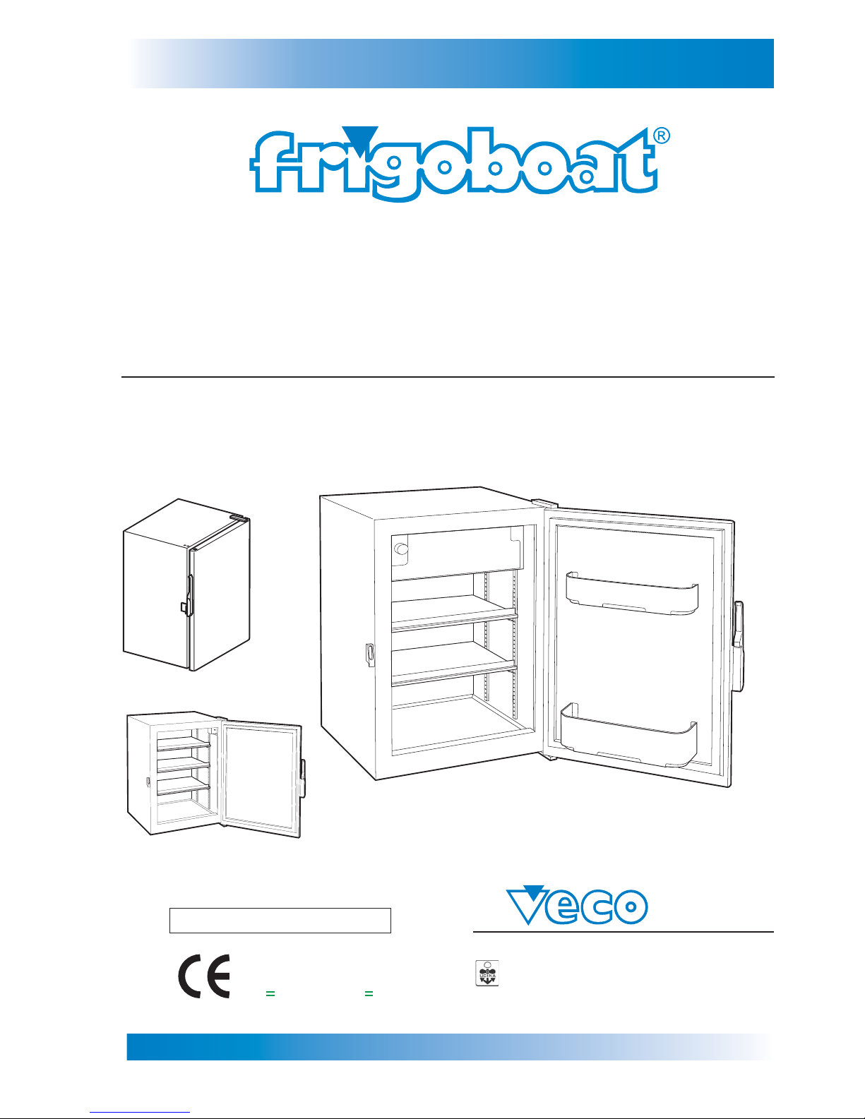
Fridges & Freezers Boxes
www.frigoboat.it
STAINLESS STEEL
FRIDGES & FREEZERS BOXES
MS SERIES
INSTALLATION, DIRECTIONS & MAINTENANCE MANUAL
S.p.A.
COMPANY
WITH QUALITY SYSTEM
CERTIFIED BY DNV
ISO 9001/2000
Via Cantore, 6 - 20034 Giussano (MI) ITALY
Tel. +39 0362.35321 - fax +39 0362.852995
[email protected]E-mail:
09/06/06
MARINE REFRIGERATION
SAINLESS STEEL
Series
Page 2
Page
1
INDEX
Fridges & Freezers Boxes
SERIE MS
STAINLESS STEEL
Series
Page
1INTRODUCTION 1
1.1 1.1 Safety 2
2 COMPONENTS TABLE
2.1 Components description (with hidden evaporator) 3
2.2 Components description (with evaporator compartment) 4
2.3 Components description (accessories for one-unit fridges/freezers) 5
2.4 Components description (accessories for multiple units)
6
3 INSTALLATION
3.1 Doors/hinges 7
3.2 Doors/handles 8
3.3 Measures 9-10
3.4 Condensation outlet 11
3.5 Multiple measures 12-13
3.6 Connection to the system / compatibility 14
3.7 Fridge/freezer - compressor connection 15-16
3.8 Fastening 17
3.9 Fastening with frame kit 18
3.10 Optional external thermostat 19
3.11 Door with panel 20
4 GOOD FUNCTIONING CHECK
4.1 Check 21
5 USE INSTRUCTIONS
5.1 Switching on 22
5.2 Switching off (no use) 22
5.3 Temperature regulation 22
5.4 Condensation tray emptying 22
5.5 Shelves regulation 23
5.6 Internal thermostat 23
5.7 Cleaning 23
6 PERIODICAL MAINTENANCE
6.1 Defrosting 24
6.2 Outlet check 24
6.3 Electrical system 24
6.4 Seals check 24
6.5 Handle check 25
6.6 Hinges check 25
7 FOODS PRESERVATION AND PLACING
7.1 Foods preservation and placing 26
8 TROUBLESHOOTING
8.1 Troubleshooting 27
Page 3

Page
2
1. INTRODUCTION
Fridges & Freezers Boxes
SERIE MS
STAINLESS STEEL
Series
1.1 Safety
Before installing the fridge it is necessary to read with great attention these instructions.
When the fridge is operating, it is better to avoid touching the freezer compartment internal
surfaces, above all with wet hands: the skin could adhere to the frozen surfaces.
Switch off the fridge to clean it or to change the light bulb or the thermostat.
Never put full glass containers in the freezer: they could break because of the expansion due
to the foods freezing.
Use precautions for children:
Don’t let children play with fridges/freezers, since the fridges/freezers doors don’t open from
inside.
Once thawed, the food must be eaten as soon as possible.
Preserve the deep-frozen packaged foods according to the producer’s
instructions.
Don’t speed up the defrosting through heating electrical fittings or
through chemical substances.
If you want to scrap the fridge/freezer, cut of f the supply cables and dismount the door so that children can’t remained trapped inside.
For your safety and for the good preservation of the food inside, keep
the precautionary measures in this manual, since the producer is not
responsible for damages due to their non-observance.
Page 4
Page
3
2. COMPONENTS TABLE
Fridges & Freezers Boxes
SERIE MS
STAINLESS STEEL
Series
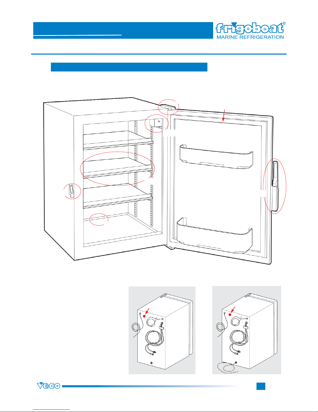
2.1 Components description (with hidden evaporator)
3.1
3.4
3.2
6.4
3.2
5.6
5.5
FRIDGE FREEZER
A = RAPID HOOK-UPS
B = THERMOSTAT
C = LIGHT
D = RECHAUFFAGE PORTE
(FILO CALOR)
E = CONDENSATION OUTLET
G = VOLTAGEWARNING LIGHT
B
C
C
B
G
A
E
A
D
G
Page 5
Page
4
2. COMPONENTS TABLE
Fridges & Freezers Boxes
SERIE MS
STAINLESS STEEL
Series
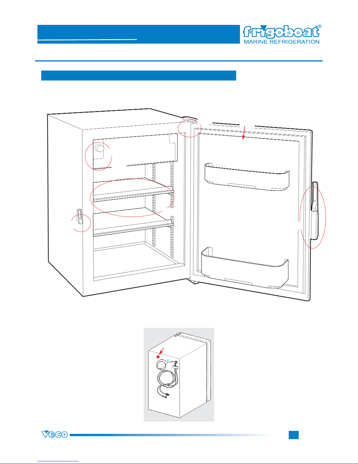
2.2 Components description (with evaporator compartment)
3.1
3.2
6.4
3.2
5.7
5.5
FRIDGE
A = RAPIP HOOK-UPS
B = THERMOSTAT
C = LIGHT
G =VOLTAGEWARNING LIGHT
C
B
G
A
5.6
Page 6
Page
5
Fridges & Freezers Boxes
SERIE MS
STAINLESS STEEL
Series
2. COMPONENTS TABLE
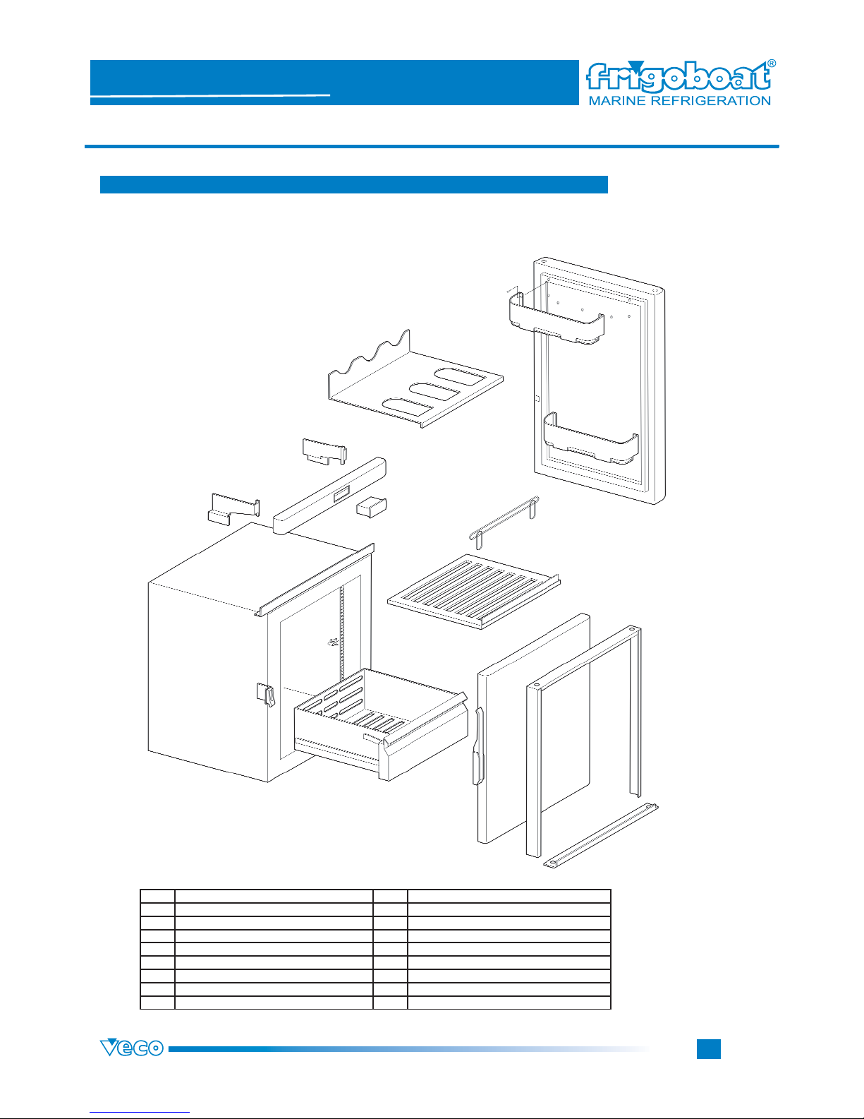
2.3 Components table (accessories for one-unit fridges/freezers)
n° Description
1 SHELVES GRILLS 9 SPACERS
2 REMOVABLE EDGE 10 RISERS
3 BOTTLES RACK SHELVES 11 THERMOSTAT HOLDERS RISERS
4 DRAWERS 12 EXTERNAL DIGITALTHERMOSTATS
5 INDEXING RACK 13 HANDLE HOOK-UP WITH SUPPORT
6 SHELVES SUPPORTS 14 HANDLE HOOK-UP WITH SUPPORT
7 DOOR BOTTLES RACK 15 DOOR PANELLING KIT
8 RISERS SUPPORTS 16 FRAME KIT
Page 7
Page
6
2. COMPONENTS TABLE
Fridges & Freezers Boxes
SERIE MS
STAINLESS STEEL
Series
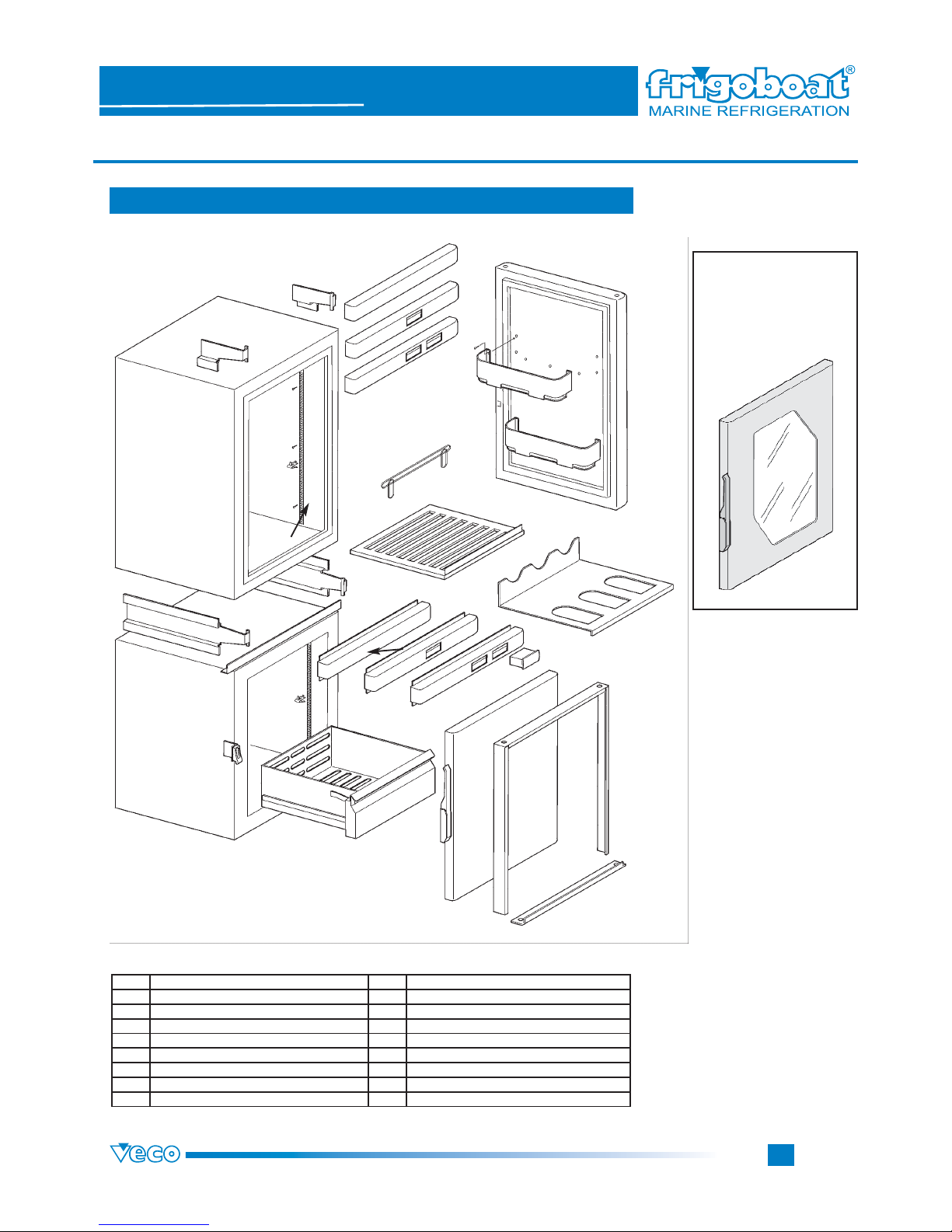
2.3 Components description (accessories for multiple units)
Special glazed
door, particularly
suitable for wine
coolers.
15
16
11
11
12
2
1
4
8
8
11
11
10
10
13
14
9
9
7
5
6
3
n° Description
1 SHELVES GRILLS 9 SPACERS
2 REMOVABLE EDGE 10 RISERS
3 BOTTLES RACK SHELVES 11 THERMOSTAT HOLDERS RISERS
4 DRAWERS 12 EXTERNAL DIGITALTHERMOSTATS
5 INDEXING RACK 13 HANDLE HOOK-UP WITH SUPPORT
6 SHELVES SUPPORTS 14 HANDLE HOOK-UP WITH SUPPORT
7 DOOR BOTTLES RACK 15 DOOR PANELLING KIT
8 RISERS SUPPORTS 16 FRAME KIT
Page 8
Page
7
3. INSTALLATION
Fridges & Freezers Boxes
SERIE MS
STAINLESS STEEL
Series
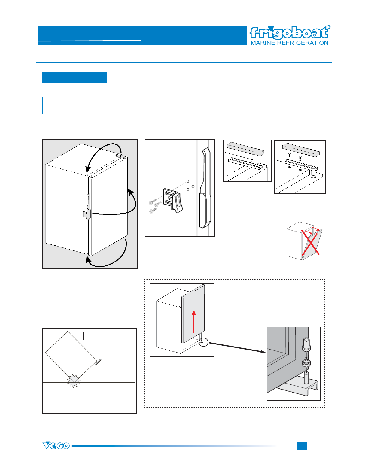
3.1 Doors/hinges
IF IT IS NECESSARY FOR INSTALLATION EXIGENCIES TO CHANGE THE OPENING, READ WITH
GREAT ATTENTION THE FOLLOWING INSTRUCTIONS.
HINGE AND HANDLE REVERSAL
Release the hinge
plastic cover.
Unscrew the hinge screws on the cabinet
top. Removing the hinge, pay attention to the
door flection. Keep it closed until the hinge pin has
been unhooked. DON’T
FLEX BACK THE DOOR.
After having unscrewed the door, screw the hinges on the opposite side (following the inverted
dismounting instructions). First of all, fasten the
inferior hinge, then hook the door and finally
fasten the superior hinge. Hook the handle to the
fridge/freezer,
Follow the instructions on page 7.
DURING THE DISMOUNTING, PAY
ATTENTION NOT TO LOSE THE RINGLETS ON THE INFERIOR HINGE.
HOOK THE DOOR PUTTING THE RINGLETS AS WE CAN SEE IN THE PICTURE.
After having hooked the handle, adjust the door. Make sure that all
screws are tightened and then screw the plastic cover.
First of all, unscrew the handle
from the door and from its support. Then unscrew the corresponding handle hook-up on
the box door side.
IMPORTANT: There are hinges both at the top and at the
bottom.
ATTENTION
Unscrewing the hinges, pay attention
not to incline the fridge/freezer to
avoid ruining its corners.
1
2
4
3
Page 9
Page
8
3. INSTALLATION
Fridges & Freezers Boxes
SERIE MS
STAINLESS STEEL
Series
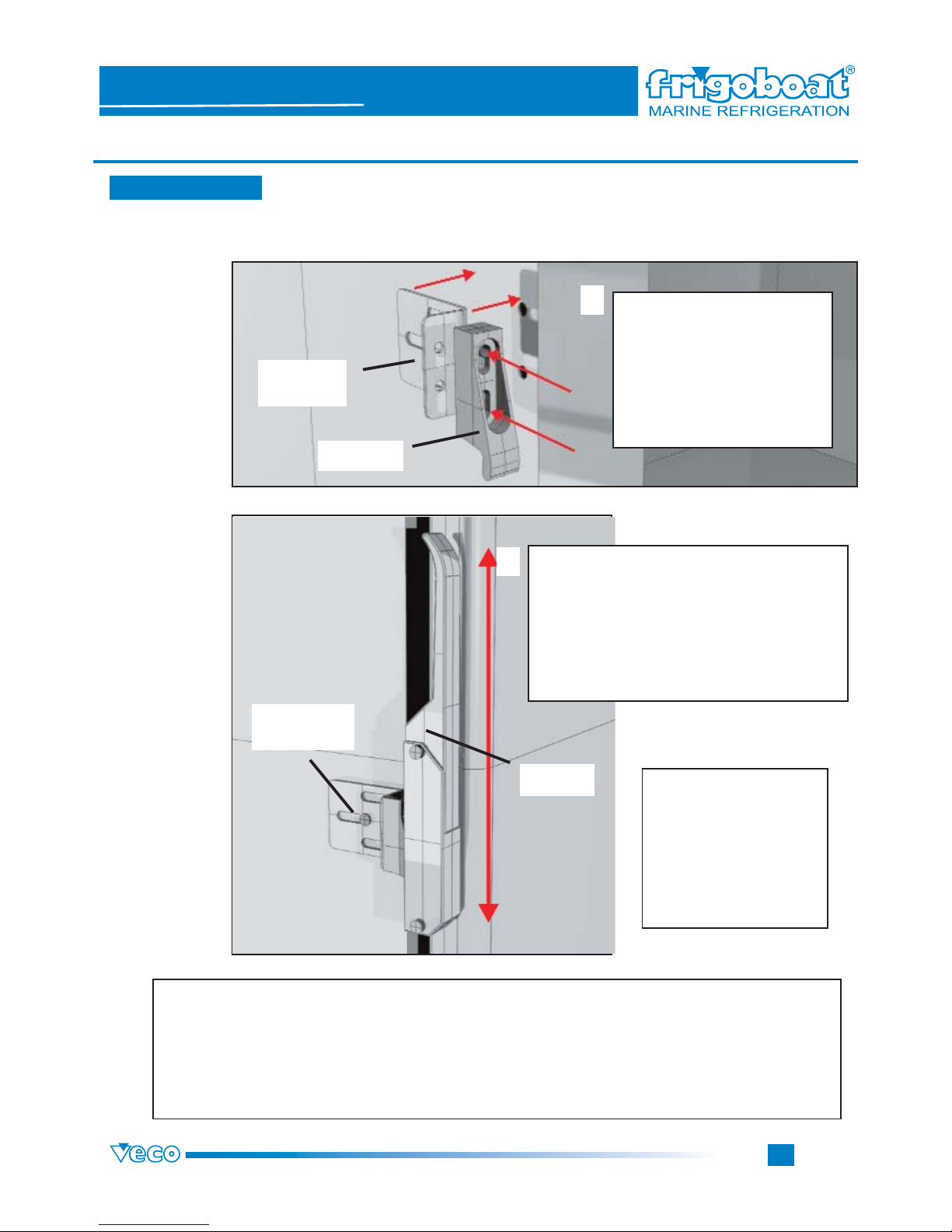
HANDLE HOOK-UP AND SETTING
Don’t tighten the screws
before having set the
handle and the hook-up,
so that they are exactly
one upon the other. Then
it is possible to tighten all
the screws.
It is very important that the handle is exactly upon its hook-up: on the contrary the
good functioning of the fastening could be impaired and some components could
break.
Handle setting
3.2 Doors/handles
IMPORTANT
Fridges/freezers have got suitable holes for the handle and
the hook-up. If you change the
opening mode, it is necessary
to dismount the hook-up from
its support and fasten it upside-down, so that the handle is
upwards.
HOOK-UP
SUPPORT
HOOK-UP
SUPPORT
HOOK-UP
HANDLE
As the hook-up, the handle too is fastened to
the fridge/freezer by means of a steel clamp. If
you change the opening mode, it is necessary
to unfasten the handle from the clamp and
fasten it again after having tipped over the
clamp. On the door there are some holes to
hook the handle support clamp and to open the
door both on the right and on the left.
2
1
Page 10
Page
9
Fridges & Freezers Boxes
SERIE MS
STAINLESS STEEL
Series
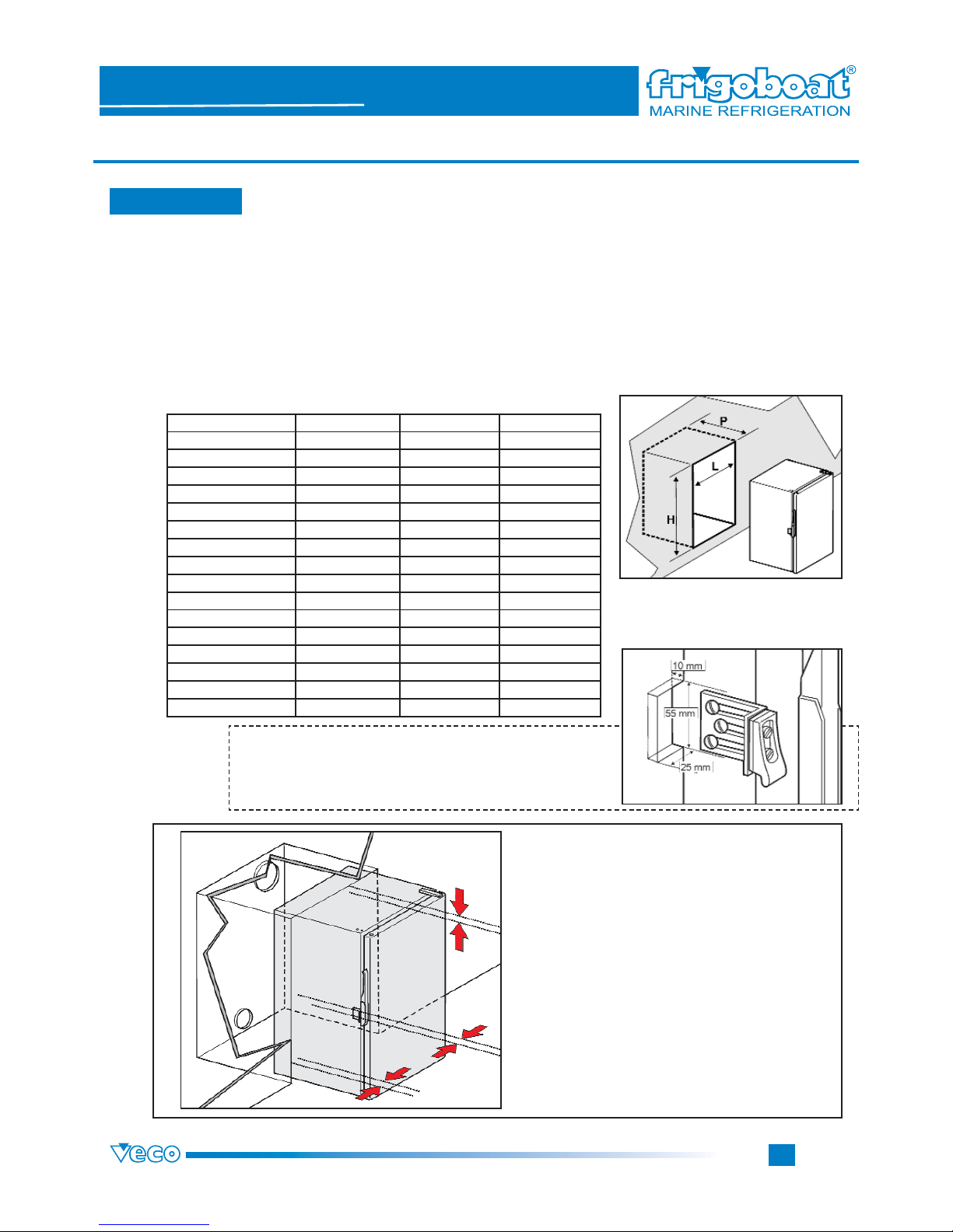
Bulk measures have been calculated counting in also eventual bulges due to the following objects:
feet: 25 mm
handle hook-up: 5 mm
hinge: 10 mm
screws bulges: 3 mm
Bulk measures
To locate the fridge/freezer, consider the following bulk measures for the different models.
3. INSTALLATION
3.3 Measures
Because of the difference in temperature between inside and outside the cabinet it is necessary to let some space (for all sides) between
the fridge/freezer walls and the walls of the surrounding pieces of furniture, it must be located
between. (Don’t remove feet!)*
The space lack for the air circulation can cause
condensation, that in the worst case can get rot
the eventual wood or cause mould on fibreglass
surfaces.
*If you must remove feet because of installation exigencies, it is necessary to create some space for the
air circulation between the cabinet and the bearing
plane.
To locate the fridge/frrezer you must consider that the
handle hook-up must be fastened in a niche as in the picture on the right.
1
2
model/litres
FRIDGE
L=lenght / mm P=depth / mm A=height / mm
42 400 342 545
80 490 415 635
115 500 465 875
130 500 510 780
160 565 530 875
180 500 465 1035
FREEZER
60 500 515 875
80 550 560 780
90 565 580 740
110 565 580 875
WINE COOLERS
115 500 515 875
130 550 560 780
160 565 580 875
Page 11
Page
10
3. INSTALLATION
Fridges & Freezers Boxes
SERIE MS
STAINLESS STEEL
Series
3.3 Measures
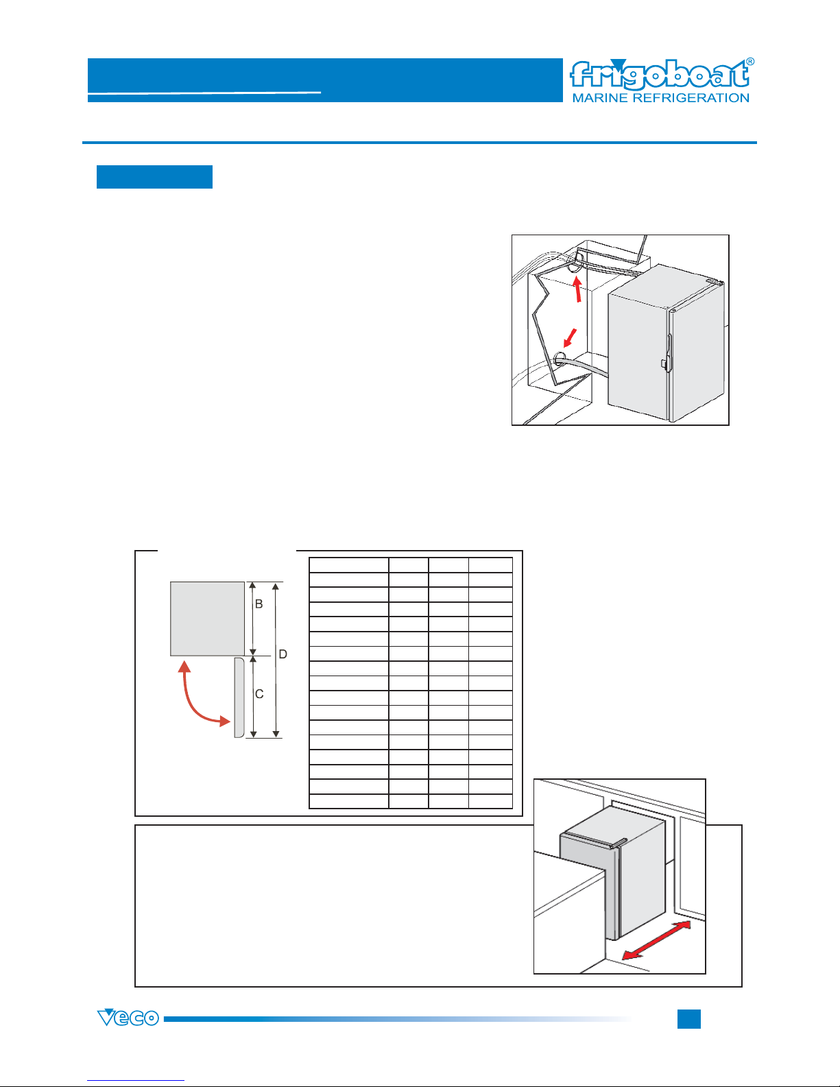
Respect area for an easy use
Locating the fridge/freezer, it is necessary to respect the surrounding area to open completely the door and
so eventually drawers and to execute easily all operations inside.
Respect area
To locate the fridge/freezer you must
consider the bulk measures on page
9, corresponding to the chosen cabinet.
Mounting instructions:
The fridge/freezer must be located easily.
Moving it, it is better to keep its protection and pay anyway great attention. If necessary, take off the door.
IMPORTANT
To locate the fridge/freezer, you must consider not only the
bulk measures on page 9 (and in the table 3.5 on pages 11-
12) but also the holes for the electrical connection wires and
for the eventual condensation outlet. Since precharged pipes
protude from the box, it is necessary a respect area: avoid
sharp bends (their radius must be superior to 50 mm).
During the fridge/freezer installation, for its maintenance, it is
IMPORTANT to make as easy as possible the accessibility to
connections, unions and waste pipes.
Model (litres)
FRIDGE C / mm B / mm D / mm
42 400 342 792
80 490 415 955
115 500 465 1015
130 500 510 1060
160 565 530 1145
180 500 465 1015
FREEZER
60 500 515 1065
80 550 560 1160
90 565 580 1195
110 565 580 1195
WINE COOLERS
115 500 515 1065
130 550 560 1160
160 565 580 1195
Page 12
Page
11
3. INSTALLATION
Fridges & Freezers Boxes
SERIE MS
STAINLESS STEEL
Series
3.4 Condensation outlet
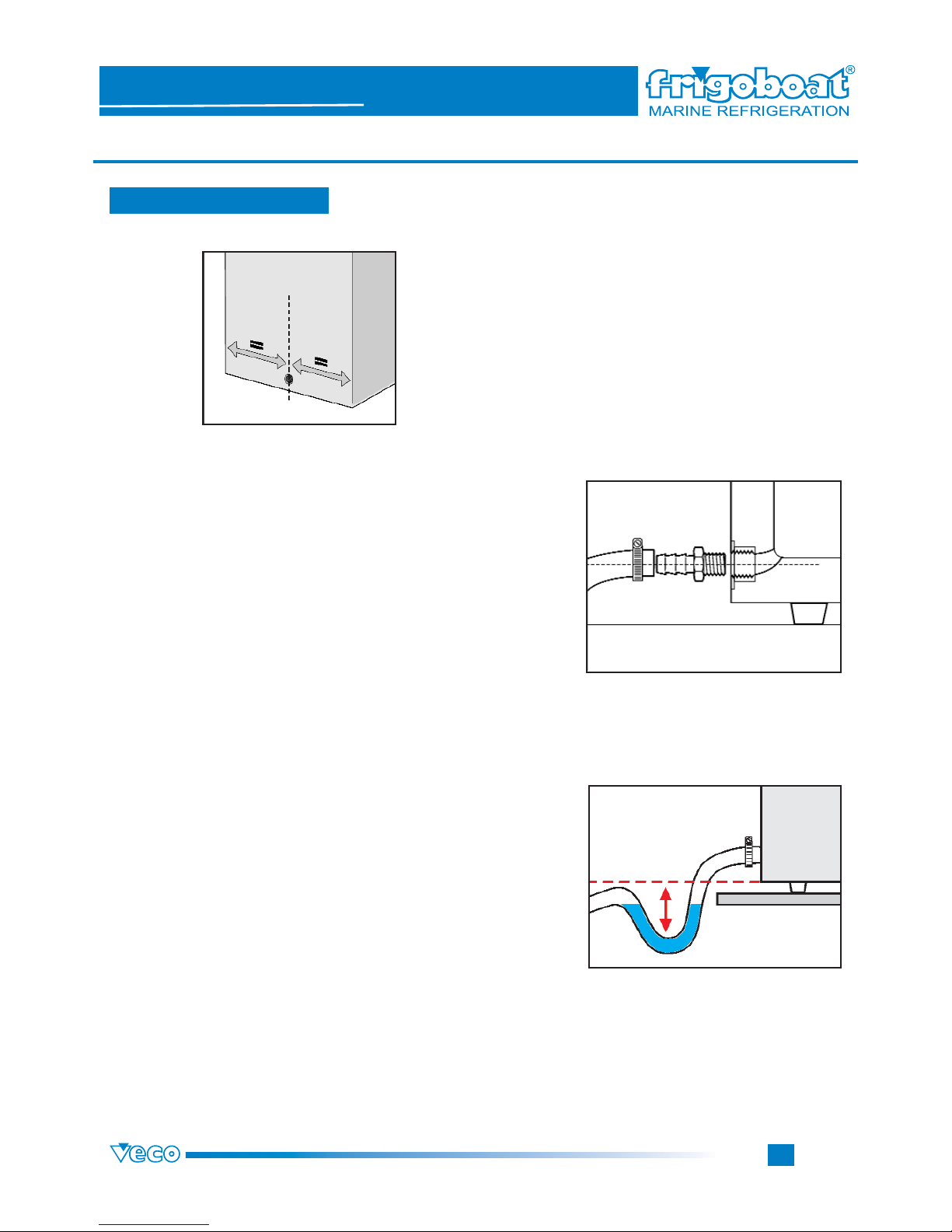
All fridges/freezers of the Stainless Steel series have got
the condensation outlet on the back side.
(as in the picture on the left)
To avoid unpleasant smells coming from condensation
trays go into the fridge/freezer, installing the condensation
outlet pipe, it is necessary to create a syphon below the
fridge/freezer level.
Pay attention to the pipe position. Locating the box in the
chosen position, don’t crush or bend in a n anomalous
way the pipe to maintain it functional.
Check also that the condensation outlet drains correctly,
pouring a congrous quantity of water into the stainless
steel cabinet when it is located and before switching it on.
Comprehensive view and position of
the condensation outlet hole
To the condensation outlet you must fasten a curve rubber holder (Cod. M68995) and connect a pipe with a
stainless steel clamp (since the fridge causes humidity
all around, pay attention to materials in contact with it).
1
2
3
4
Page 13
Page
12
3. INSTALLATION
Fridges & Freezers Boxes
SERIE MS
STAINLESS STEEL
Series
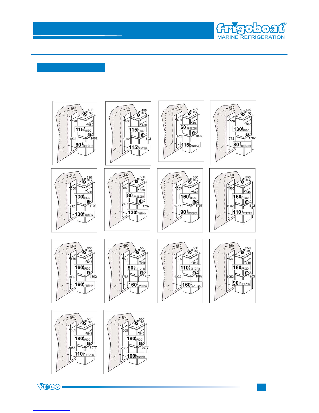
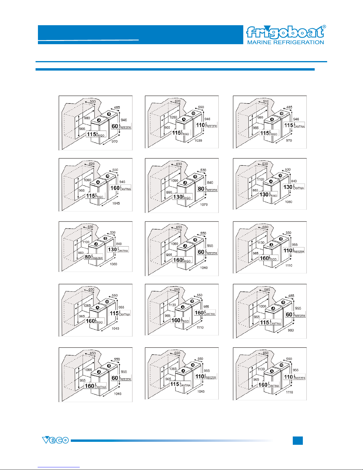
3.5 Multiple measures
Column disposition of the stainless steel boxes in the different compatible and advisable models with
intermadiate supports for control display in the centre and at the top (line 1) or only in the centre (line 2).
Page 14
Page
13
3. INSTALLATION
Fridges & Freezers Boxes
SERIE MS
STAINLESS STEEL
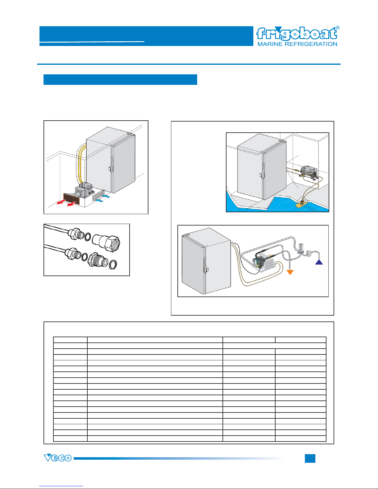
Series
Horizontal disposition of the stainless steel boxes in the different compatible and advisable models with
the intermediate supports for the control display on the boxes.
Page 15
Page
14
3. INSTALLATION
Fridges & Freezers Boxes
SERIE MS
STAINLESS STEEL
Series
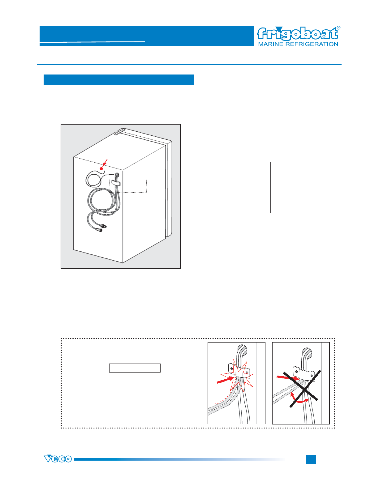
3.6 Connection to the system / compatibility
Refrigerating systems specifications
AIR REFRIGERATING SYSTEM
WITH OUT-HULL EXCHANGER
WITH SEA WATER PUMP
Compatibility table
WATER REFRIGERATING SYSTEM
The connection to the compressor
unit is easier thanks to the rapid
couplings which must not be soldered. All pipes with rapid couplings
are already precharged.
Model (litres)
fridge AIR REFRIGERATING SYSTEM WATER REFRIGERATING SYSTEM
WITH OUT-HULL EXCHANGER WITH SEA WATER PUMP
42 MADRID 35 F; PARIS 35 F; ROMA35 F
80 MADRID 35 F; PARIS 35 F; ROMA35 F
115 ELBA 35 F; CAPRI 35 F
130 ELBA 35 F; CAPRI 35 F
160 ELBA 35 F; CAPRI 35 F
180 ELBA 35 F; CAPRI 35 F SUPERFRIGOMATIC K 50 F SUPERFRIGOMATIC W 50 F
freezer
60 FRIGOMATIC AH 35 F; FRIGOMATIC AV 35 F; FRIGOMATIC CAPRI 50 F; AHL 35 F FRIGOMATIC K 35 F FRIGOMATIC W 35 F
80 FRIGOMATIC AH 35 F; FRIGOMATIC AV 35 F; FRIGOMATIC CAPRI 50 F; AHL 35 F FRIGOMATIC K 35 F FRIGOMATIC W 35 F
90 FRIGOMATIC K 50 FRIGOMATIC W 50
110 FRIGOMATIC K 50 FRIGOMATIC W 50
wine coolers
115 ELABA 35 F; CAPRI 35 F
130 ELBA 35 F; CAPRI 35 F
160 ELBA 35 F; CAPRI 35 F SUPERFRIGOMATIC K 50 F SUPERFRIGOMATIC W 50 F
Page 16
Page
15
3. INSTALLATION
Fridges & Freezers Boxes
SERIE MS
STAINLESS STEEL
Series
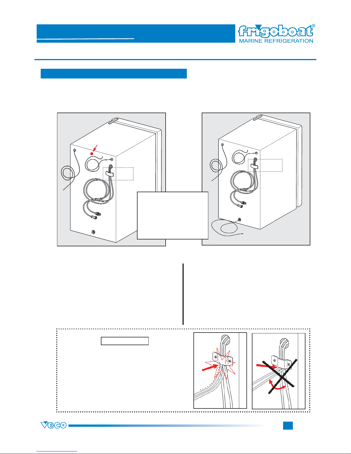
3.7 Fridge/freezer - compressor connection
PAY ATTENTION BENDING PIPES (AS WE CAN
SEE IN THE PICTURE). AVOID ANGLES AND
BEND PIPES FORMING AWIDE RADIUS.
A SHARP BEND COULD IMPAIR THE GOOD
FUNCTIONING OF THE EVAPORATOR.
To install a fridge/freezer with evaporator compartment and condensation tray,
it is necessary to connect:
1) the pipes to the compressor unit (A)
2) the thermostat wires (B)
3) the internal light wires (C - 12 or 24 V)
CONNECTIONS FOR CABINETS OF MS SERIES
WITH EVAPORATOR COMPARTMENT AND CONDENSATION TRAY
ATTENTION
FRIDGE
SEE
BOX 1
BOX 1
A = RAPID HOOK-UPS
B = THERMOSTAT
C = LIGHT
D = RECHAUFFAGE PORTE
(FILO CALOR)
E = CONDENSATION OUTLET
G = VOLTAGE WARNING LIGHT
A
C
B
G
Page 17
Page
16
Fridges & Freezers Boxes
SERIE MS
STAINLESS STEEL
Series
PAY ATTENTION BENDING PIPES (AS WE CAN
SEE IN THE PICTURE). AVOID ANGLES AND
BEND PIPES FORMING AWIDE RADIUS.
A SHARP BEND COULD IMPAIR THE GOOD
FUNCTIONING OF THE EVAPORATOR.
To install a fridge/freezer with hidden evaporator, it is necessary to connect:
FOR THE FRIDGE
1) the pipes to the compressor unit (A)
2) the thermostat wires (B)
3) the internal light wires (C - 12 or 24 V)
4) the condensation outlet pipe (E - on page 11)
FOR THE FREEZER
1) the pipes to the compressor unit (A)
2) the thermostat wires (B)
3) the internal light wires (C - 12 or 24 V)
4) the FILO CALOR
CONNECTIONS FOR FRIDGES AND FREEZERS WITH HIDDEN EVAPORATOR
ATTENTION
FREEZER
with hidden evaporator
FRIDGE
with hidden evaporator
SEE
BOX 1
SEE
BOX 1
BOX 1
A = RAPID HOOK-UPS
B = THERMOSTAT
C = LIGHT
D = RECHAUFFAGE PORTE
(FILO CALOR)
E = CONDENSATION OUTLET
G = VOLTAGE WARNING LIGHT
A
A
E
D
B
B
C
C
G
3. INSTALLATION
3.7 Fridge/freezer - compressor connection
Page 18
Page
17
3. INSTALLATION
Fridges & Freezers Boxes
SERIE MS
STAINLESS STEEL
Series
3.8 Fastening
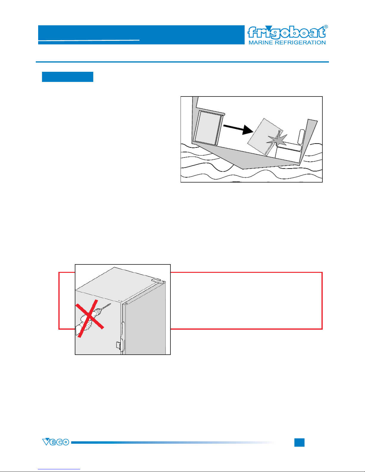
The Stainless Steel boxes must be
fastened to the structure, even if
they have a precise position.
In fact, if the box hasn’t been fastened, it
could occasionally moves according to the
hull movements and even if it doesn’t cause
immediately any damages, then it could ruin
the connection pipes (break of the connec-
tion pipes to the system and detachment of
the condensation discharge pipe or of the
electrical connections).
ALL NECESSARY HOLES HAVE ALREADY BEEN
ARRANGED WITH RINGLETS.
DON’T DRILL ANY HOLE INTO THE
BOX.
YOU COULD IMPAIR IRREMEDIABILY
THE EVAPORATOR.
Page 19
Page
18
Fridges & Freezers Boxes
SERIE MS
STAINLESS STEEL
Series
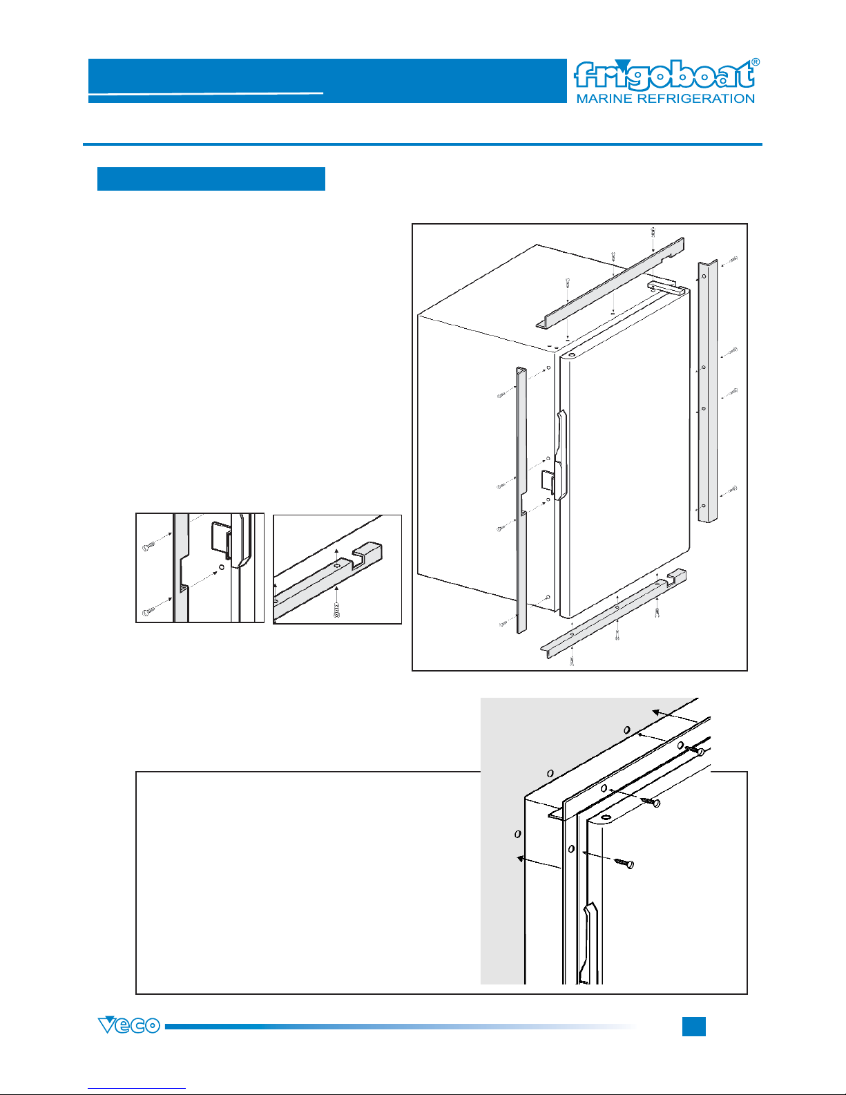
If you want to fasten the box using the frames, it is
necessary to drill into its walls some holes, as you
can see in the picture.
You can drill some holes only before mounting the
frames. Then you must consider also the material
they must be fasten to and the screws head.
On the box walls there are some holes to
fasten stainless steel profiles (picture 4), that
fit perfectly the cabinet in the chosen seat
(picture 4).
On the profiles there are some holes to fix
them on the box (the kit includes screws) .
Pay attention to the hinges and the handle
position since the profiles have their own join
seats (pictures 2 and 3).
How to fasten the box with the
frame kit
3. INSTALLATION
3.9 Fastening with frame kit
picture 1
picture 2
picture 3
picture 4
Page 20
Page
19
3. INSTALLATION
Fridges & Freezers Boxes
SERIE MS
STAINLESS STEEL
Series
3.11 Optional external thermostat
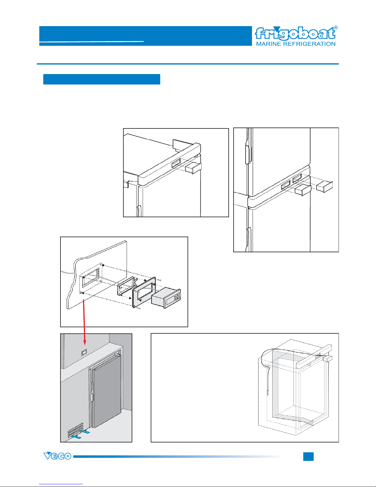
It is possible to install digital thermostats for fridges and freezers. You can insert these thermostats in the
risers (as you can see in the picture) if it is a one-unit or in the risers/spacers if it is a multiple unit, composed
by fridge and freezer (see “Components table” on page 5-6).
The digital thermostat has not to be installed near the
box. In this case you can fix it on the wall, as you can see
in the picture, through a stainless steel frame.
You must put the bulb of the digital
thermostat in the fridge/freezer (A).
The wire must pass into the hole of
the box back (B). Then it must follow
the internal edge line. The correct
position is at half height. The bulb
must not come into contact with the
walls and the food inside.
The wire must be fastened by an aluminium adhesive tape or by some
silicone. It is necessary to seal the
hole.
B
A
Page 21
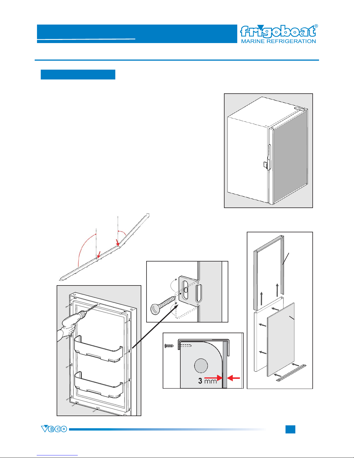
It is possible to panel both the fridge and the freezer door.
The kit includes one single profile to be bent.
To fasten them, follow these instructions:
1 - take down the door (instructions on page 7 - 3.1);
2 - bend the profile along the arranged line (picture 1);
3 - bend inside tongues to 90° (picture 2);
4 - drill a hole into the door inside next to the tongues (picture 3);
5 - locate the panel (3 mm thick) (picture 4);
6 - locate the panel C and the frame composed by the two ele-
ments: A and B (picture 5);
7 - tighten the screws;
8 - take up the door (instructions on page 7 - 3.1)
Page
20
3. INSTALLATION
Fridges & Freezers Boxes
SERIE MS
STAINLESS STEEL
Series
3.12 Door with panel
A
picture 2
picture 5
picture 4
picture 3
picture 1
C
C
B
Page 22
Page
21
4. GOOD FUNCTIONING CHECK
Fridges & Freezers Boxes
SERIE MS
STAINLESS STEEL
Series
To execute the check, after having made all the connections, both the electrical connections and the connections to the pipes, switch on the fridge/freezer and set the thermostat to half way between maximum and minimum: within a minute the compressor will
start automatically.
4.1 Check
Make sure that all the connections have been correctly made.
Press the switch on, that is
on the main electrical panel
or elsewhere according to
the installation.
Set the thermostat to
ON.
If the connections have been correctly
made, within a minute the compressor
will start and the fridge/freezer will
cool down.
1
2
3
4
CHECK PHASES
Page 23
Page
22
5. USE INSTRUCTIONS
Fridges & Freezers Boxes
SERIE MS
STAINLESS STEEL
Series
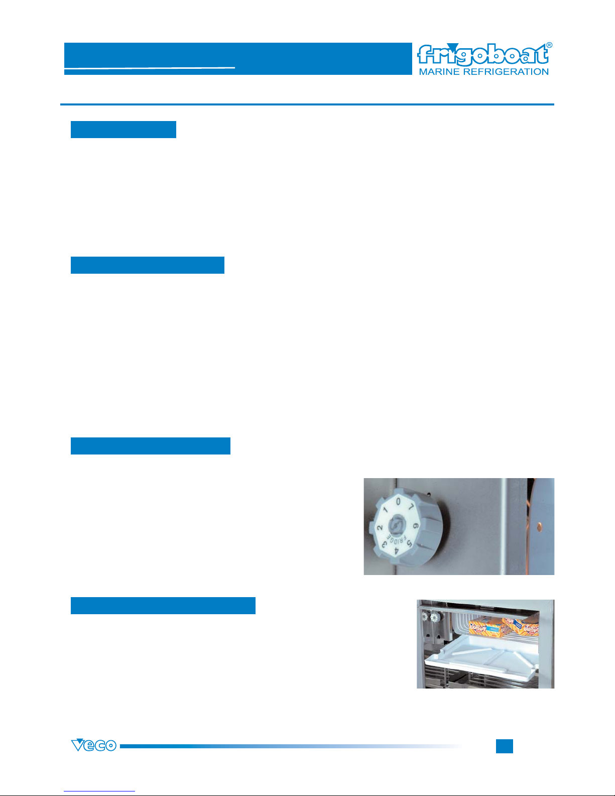
5.1 Switching on
5.2 Switching off (no use)
5.3 Temperature regulation
If you don’t use the equipment for a long time, follow these instructions:
- cut off the power to the fridge/freezer circuit;
- take off the foods from the fridge/freezer and defrost the latter, emptying frequently the condensation tray, and clean it.
Then, don’t close the door to avoid mould and bad smells.
To switch on the fridge/freezer, check that that the power is available and turn
the thermostat to ON to start the compressor. After few minutes the fridge/freezer will cool down. Then wait for 20 minutes before putting the food inside.
To regulate the temperature in the fridge/freezer, turn the thermostat to the desired temperature and wait for some minutes
until it is reached. If it is the first switching on after a long period
of no use, wait for some minutes and check that the fridge/freezer is cooling down.
5.4 Condensation tray emptying
In the models equipped with the tray, while the fridge/freezer is operating, it is
advisable to check at least once a week if there is eventually water in the tray.
In this case, empty it and mop it well to avoid mould and bad smells.
Page 24
Page
23
5. USE INSTRUCTIONS
Fridges & Freezers Boxes
SERIE MS
STAINLESS STEEL
Series
5.5 Shelves regulation
5.6 Light bulb change
5.7 Cleaning
The light bulb is in a stainless steel shell at the top on the
right. On the inetrnal side there is the switching on button.
To change the light bulb, unscrew it and change it with a
new one of the same model.
(Switching off the fridge/freezer before changing the light
bulb)
Check the light bulb voltage:
If it is 12 V, use the light bulb (Cod. G270423)
If it is 24 V, use the light bulb (Cod. G270425)
Before cleaning the fridge/freezer, it is necessary to cut off
the power.
You must clean the fridge/freezer only with warm water,
using a soft cloth.
After having cleaned it, it is possible to give again the power
to the fridge/freezer.
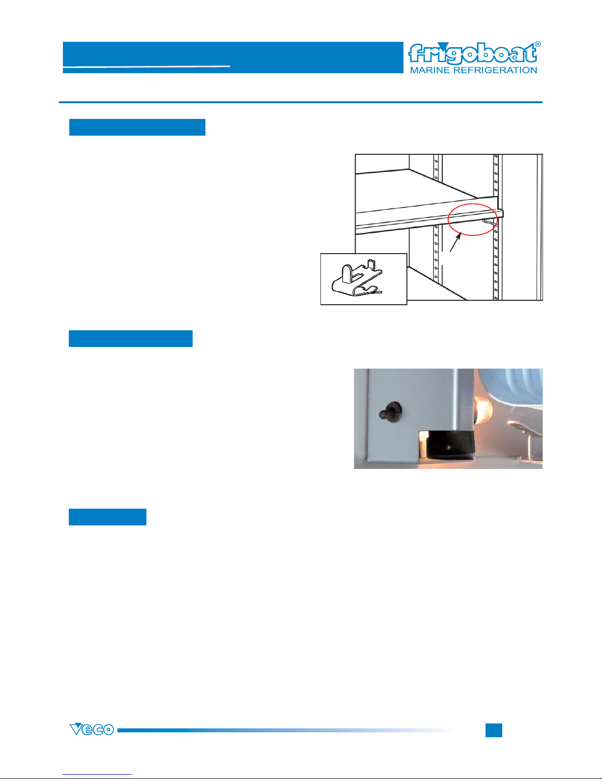
To regulate the shelves in the box there are four indexing
racks (two for each sides), to which must be fastened the
shelves supports (1). It is necessary to fasten the four supports at the same level, so that the shelf is perfectly horizontal.
To hook the supports to the grill look at the picture on the
right and repeat the operation for each support.
1
1
Page 25
Page
24
6. PERIODICAL MAINTENANCE
Fridges & Freezers Boxes
SERIE MS
STAINLESS STEEL
Series
6.2 Outlet check
6.3 Electrical system check
6.1 Defrosting
We suggest to defrost the freezer or the deep-frozen foods compartment when
the ice is more than 4-5 mm thick. Before defrosting it, it is necessary to empty
the deep-frozen foods compartment. Make sure that the condensation tray
doesn’t contain water and during the defrosting pay attention that it doesn’t fill
up.
To check that the outlet discharge drains correctly, pour some water in the hole
at the bottom by the fridge/freezer back wall: the water should flow fluently. On
the contrary, it is necessary to clean the clogged outlet.
In the fridges with evaporator compartment there is no condensation outlet,
since there is a tray just below the evaporator to collect the condensation. It is
necessary to empty the tray before it fills up completely (see 6.1).
It is advisable to check periodically both the fridge/freezer and the compressor
electrical circuit to guarantee the system safety. In fact, a short circuit could
damage the compressor electrical system and cause a fire on the boat.
6.4 Seals check
When the fridge/freezer is off, it is advisable to check sometimes seals and
clamps, used to hook the condensation outlet pipes.
Page 26

Page
25
6. PERIODICAL MAINTENANCE
Fridges & Freezers Boxes
SERIE MS
STAINLESS STEEL
Series
6.5 Handle check
If it is difficult, using the fridge/freezer, to open or close it, we suggest to check
the handle and the hook-up alignment, the handle is hooked to, to avoid any
damages (see 3.2 on page 7).
It is also useful to check sometimes the handle even if the fridge/freezer door
opens and closes easily.
6.7 Hinges check
Check that the hinges screws don’t loosen because of the boats vibrations,
since they could impair the fridge/freezer opening and closing.
Page 27
Page
26
7. FOODS PRESERVATION AND PLACING
Fridges & Freezers Boxes
SERIE MS
STAINLESS STEEL
Series
7.1 Preservation times table
WHATTODO
- Open the fridge only if necessary.
- Wrap up cheeses and other odorous foods with the silver paper or put them in food containers.
- Defrost the refrigerating compartment before the ice gets 10 mm thick. Then clean it with a bicarbonate solution by
means of a sponge. Rinse and dry carefully.
- When you don’t use the fridge/freezer, let it open. If is has a front opening, block the door so that it can’t close.
WHAT TO AVOID
- Put in the fridge warm foods.
- Defrost the ice using sharp objects.
- Put foods in the evaporator compartment without any protection.
- Clean the fridge using chemical solvents, although diluted in water.
HOW TO PLACE FOODS
FRIDGE
- Put in the fridge the hermetic packaging.
- Wrap up meat, fish and vegetables, etc....with food paper or put them in food containers.
- Don’t cover grills with paper or trays. Keep some distance between foods to let the air circulate.
- Choose different height shelves according to the food preservation temperature: at the top it’s warmer; at the
bottom it’s cooler.
FREEZER
- Put the deep-frozen packaged foods in the freezers without taking off their packaging.
- To deep-freeze, divide foods in little portions and wrap up separately each one using food paper. Put them in the
most cold compartment area.
Because of power lack and considering the installation specificity, it is better to avoid deep-freezing foods.
The food that must be deep-freeze must not get into contact with the deep-frozen food.
At the freezer bottom, there must be a grill so that deep-frozen foods don’t get into contact with the bearing plane., if
it doesn’t belong to the evaporator.
ICE CUBES PRODUCTION
- Use the ice tray for the evaporator with its portioned plastic bag (A090900 and A090901).
Page 28

Page
27
8. TROUBLESHOOTING
Fridges & Freezers Boxes
SERIE MS
STAINLESS STEEL
Series
8.1 Troubleshooting
Before calling an Authorized Assist ance Centre , we suggest some checks to solve the most common cases of bad func tioning, not directly caused by material defect s or inst allation errors.
If the system wouldn t work af ter having checked it, call the nearest Frigoboat
Authorized Assist ance Centre
.
To have some information about the nearest Authorized Assist ance Centre, call the V e c o service ( +39.0362.35321 ) or go
to the WEB page w w w .frigoboat.it
NOTE:
W ait one minute: there is up to one minute delay between the power ON and the compressor st arting. Allow enough time.
8.1 - THE BOX IS TO O COLD OR THE COMPRESSOR RUNS CONTINUOSLY
8.1.1 - T urn the thermost at clockwise towards 1 . If the box is still too cold with thermost at set at 1 , then stop the com pressor, putting the thermost at to 0 or switching of f the fridge switch. Use this switch to make run the compressor for 15
minutes every 1 - 3 hours to keep the box at the normal temperature (+2 / -6 ). The unit must be checked by a Frigoboat
Authorized Service.
8.2 - THE BOX IS NOT COLD ENOUGH A LTHOUGH THE COMPRESSOR RUNS NORMALLY
8.2.1 - Remove any warm food from the box and let it cool down to ambient temperature before storing it again.
8.2.2 - The door must be perfectly closed and the door gasket s must fit perfectly . Nothing must prevent the door gasket
to seal.
8.2.3 - Check that there are no obstructions in the compressor air int ake and outlet and the condenser is clean.
8.2.4 - When the compressor is running, the fan should run in air-cooled models and the pump should run and the water
flow in W models. Otherwise it is necessary to clean the filter.
8.3 - THE COMPRESSOR STARTS BUT STOPS ALMOST IMMEDIATELY AFTERW ARDS
8.3.1 - Check the battery charge. If necessary, charge the battery.
8.3.2 - Check that all the connections and the fuse of the battery supply to the Frigomatic are well tightened and not cor roded. In winter the compressor temperature should be above 0 C.
8.3.3 - Disconnect the F terminal from the electronic control. If the compressor runs correctly , check the fan, the pump
or the pump relay as the amperage is too high. As soon as you can, the unit shoul be checked by a Frigoboat Authorized
Assist ance Centre.
8.4 - THE COMPRESSOR DOESN T STA R T
8.4.1 - There is a delay between the power ON and the compressor st arting. W ait one minute.
8.4.2 - On the electronic control check that the + and - volt age is 12 V (24 V) and the thermost at has been set on 7 .
 Loading...