

Frigiking FD350, FD450, FS350, FS450, FD650 Owner's Manual
...
Owner’s Guide
Use and Care Manual
Ducted Cooler Models:
FD350, FD450, FD650
FS350, FS450, FS650
Customer Service
1-800-325-6952
• Safety
• Installation
• Start-up
Congratulations: You have purchased a product of superior performance and design, which will give the best service when
properly installed, operated and maintained.
This guide will provide you with information needed to assemble the unit. It also contains information on how to safely operate,
inspect, maintain and troubleshoot your Frigiking evaporative air cooler.
• Operation
• Maintenance
• Troubleshooting
WARNING - TO REDUCE THE RISK OF FIRE, ELECTRICAL SHOCK, OR INJURY TO
PERSONS, OBSERVE THE FOLLOWING:
READ AND SAVE THESE IMPORTANT SAFETY INSTRUCTIONS
• Read all instructions carefully before installation.
• Cooler motor, pump, cabinet and junction box must be
grounded in accordance with all local and national codes.
A ground wire must be used between the cooler and the
power source.
• Always disconnect electrical power to the cooler before
working on cooler.
• WARNING To reduce the risk of re or electrical shock
do NOT use this fan with any solid state speed control
device.
• Do NOT remove side panels while cooler is running.
• Do NOT operate with evaporative pad removed.
• Do NOT locate cooler near exhaust or vent pipes as
odors or fumes may be drawn into the unit.
• Be sure cooler is connected to proper line voltage
stamped on blower motor and pump motor specication
plate.
NOTE: IMPROPER VOLTAGE WILL VOID MOTOR
WARRANTY.
• Your warranty does NOT cover shipping damage. Report
all shipping damage at once to store making the delivery.
THE USE OF ANODE DEVICES, CHEMICAL ADDITIVES, OR
COOLER CLEANER TREATMENTS IN THIS COOLER WILL
VOID THE WARRANTY.
• For future reference, record the model and serial number,
date and place of purchase of your evaporative cooler
here:
Model # Serial #
Date of Purchase:
Place of Purchase:
Serial # can be found outside the cabinet.
1-999-1539 REV A09/11/17
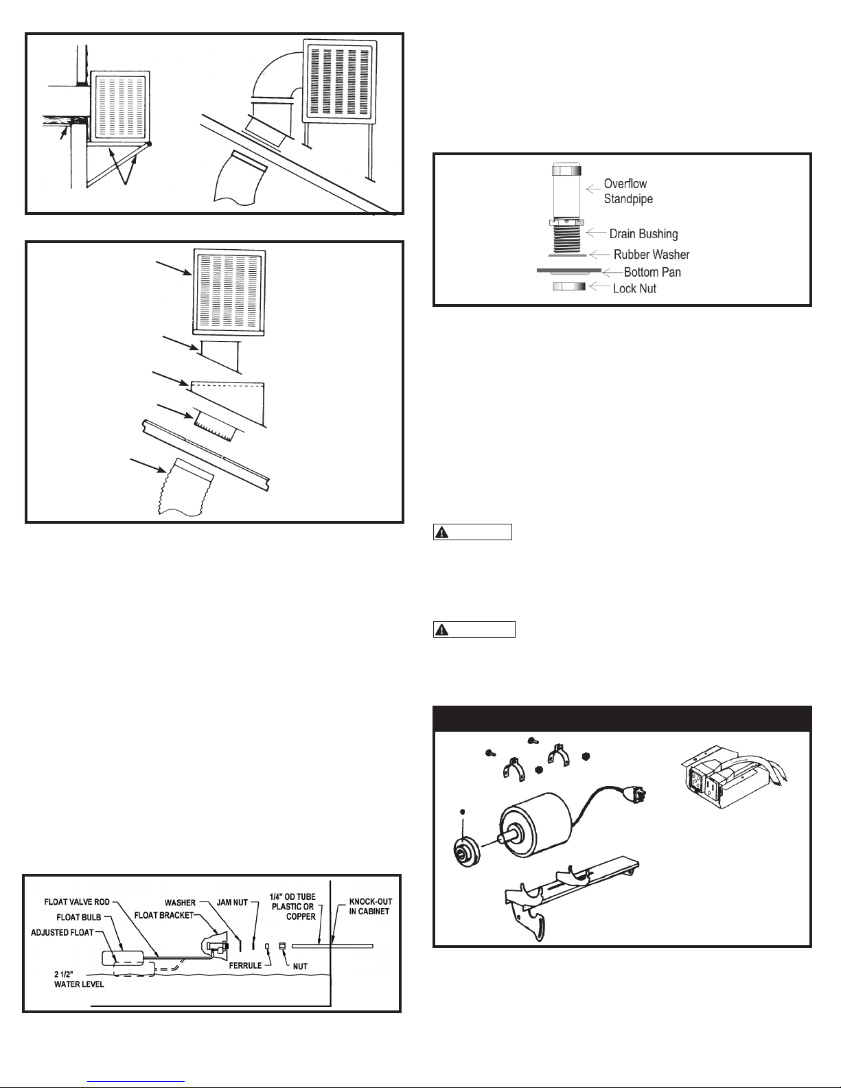
ROOF
DUCT
CEILING
WOOD OR ANGLE
IRON SUPPORT
TYPICAL SIDE DISCHARGE
COOLER
DUCT
WATER CONNECTION Continued
2. Turn water to cooler on and set oat valve to maintain 2 1/2" water depth.
The oat valve is adusted by bending the oat valve rod.
3. Bleed-off: Bleed off is helpful to prevent scale from building up in the
cooler. A bleed-off adapter tee and tube are furnished with the cooler for
this purpose. Run bleed-off line to a proper drain.
Note: Evaporative coolers should not be connected to
a "soft" water system.
ROOF JACK
COOLER STAND
*COLLAR (with ange)
*FLEX DUCT
TYPICAL DOWN DISCHARGE
INSTALLATION
Installation requires connection of blower opening to existing air ducting
system or to a dropper duct with a ceiling diffuser. In either instance, building
modication is necessitated. The bottom discharge cooler is always mounted
on the roof of the structure. This will require a roof stand, roof jack, exible
duct and collar to connect to existing ductwork. If installation is being
made by other than a professional HVAC contractor, it is suggested that the
installation be throughly discussed with a professional sales person familiar
with cooler installation and that printed instructions be requested for the
installation equipment and supplies purchased.
DO NOT DRIVE NAILS OR SCREWS INTO BOTTOM OF
COOLER, THIS WILL CAUSE IT TO LEAK WATER AND
WILL VOID THE WARRANTY.
DRAIN BUSHING
Insert drain bushing through the hole in the cooler bottom pan. Attach nut
securely and hand tighten. Do NOT use a wrench.
WALL SWITCH: For one or two speed (120 ro 240 volt) use switch kit
available from your dealer.
ADJUSTABLE MOTOR PULLEY (SHEAVE): This part is set at
the factory for proper motor load and maximum air delivery of a cooler not
connected duct and register system. When cooler is connected to a duct
system the cooler air capacity and motor amperage decrease due to static
pressure (duct resistance). The adjustable motor pulley is used ONLY to
compensate for duct system resistance by returning cooler and motor to
proper load capacity and should not be adjusted except for that purpose.
CAUTION: AMPERAGE OF MOTOR MUST BE CHECKED
TO MAKE CERTAIN IT DOES NOT EXCEED THE MAXIMUM
ALLOWED AS STAMPED ON MOTOR SPECIFICATION PLATE.
Only persons with proper electrical equipment and thorough knowledge of
adjustable pulleys should attempt adjustment of your cooler.
WARNING: IMPROPER PULLEY ADJUSTMENT CAN
OVERLOAD AND BURN OUT MOTOR AND VOID WARRANTY.
MOTOR KITS
120 VOLT MOTOR KIT
* FOR MOBILE HOME INSTALLATION SEE SEPARATE
INSTRUCTION SHEET IN GRILL KIT BOX.
Whenever the cooler is mounted, the surface must be level. This is necessary
so that the water in the reservoir and in the troughs of the pad frame will be
level when the cooler is operating.
WATER CONNECTION
1. Install oat in hole provided in oat bracket. See parts illustration to route
water line. Connect per above sketch.
INSTALLATION
1. Install the motor in the mounting cradle as shown.
2. Remove the junction box from the cooler.
3. Wire the pump and motor receptacles per the schematic shown below.
4. Place both receptacles in the junction box as shown and re-attach the
junction box to the cooler top.
Page 2
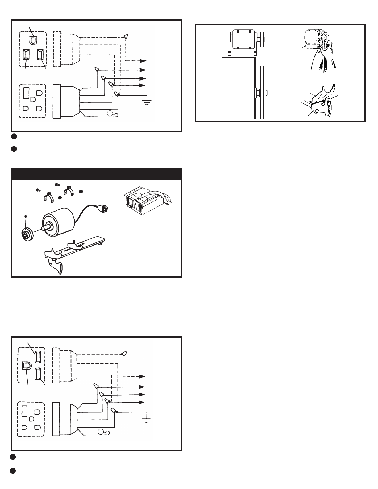
A
B
Green
Black
White
15A 120V
5 Pin
Motor
Recp.
Red
Black
White
Green
Orange
GND
Green
White
Black
Red
Pump
Black
Green
White
Lo
Hi
Com
Power
Supply
3 Pin
A
Orange
5 Pin
Motor
Recp.
Red
Black
Orange
Green
White
GND
Green
Orange
Black
Red
Pump
Black
Green
Orange
Lo
Hi
Com
Power
Supply
3 Pin
B
120 VOLT MOTOR KIT
Green
Black
Green
3 Pin
White
Pump
Black White
15A 120V
Black
Red
Black
White
Green
Lo
Hi
ComRed
White
5 Pin
Green
Orange
A
GND
Motor
Recp.
The orange wire is not used. Double it over and cover the bare end with
A
electrical tape.
The red wire is not used on single speed motors. Double it over and cover
B
the bare end with electrical tape or wirenut.
240 VOLT MOTOR KIT
OPERATION
Power
Supply
BLOWER BELT ADJUSTMENT
Correct belt tension adjustment is important. Incorrect adjustment increases
power consumption and shortens belt and motor life.
Install belt over motor and blower pulleys.
(A) check belt tension by squeezing (deecting) belt. Proper tension will allow
deection of 1/2 to 3/4 inch.
(B) To increase or decrease belt tension, loosen bolt in slot of motor support
brcket. Adjust belt to desired tension and re-tighten bolt.
PRE-WET PADS
For maximum cooling efciency, prior to the initial start up of the cooler
remove the pad frame assemblies from the cooler and spray the pad and
frames thoroughly with water from a garden hose.
INSTALLATION
1. Install the motor in the mounting cradle as shown.
2. Remove the junction box from the cooler.
3. Remove 120 volt pump and pump receptacle furnished with cooler and
replace it with the 240 volt LSP-94 pump and pump receptacle. (see
replacement parts list)
4. Wire the pump and motor receptacles per the schematic shown above.
5. Place both receptacles in the junction box as shown and re-attach the
junction box to the cooler top.
Green
Black
Green
3 Pin
Black Orange
15A 230V
Orange
Red
Black
Red
Black
Orange
Green
Pump
Lo
Hi
Com
Orange
5 Pin
Green
White
A
GND
Motor
Recp.
The white wire is not used. Double it over and cover the bare end with
A
electrical tape or wirenut.
The red wire is not used on single speed motors. Double it over and cover
B
the bare end with electrical tape.
Power
Supply
Put the pad frame assemblies back on the cooler and while the pads are still
wet start the cooler with the pump on.
BUILT-IN WINTER CLOSURE (Down discharge units only)
An exclusive feature of your cooler (models in the 4800 to 6800 CFM range)
which is provided is the full closure damper. Your cooler is shipped from the
factory with the damper temporarily fastened to the side of the blower with a
shipping screw. Remove the screw and store the damper for later use during
winter months.
1. For Winter use of a damper, slide damper into cooler below the blower.age.
2. When starting the cooler in the Spring, remove the damper and store in a
safe place.
Page 3
 Loading...