

Frigidaire FPF312ASA, FSF312ASA, FLF316AQA, TGF317AWA, TGF317AUA Installation Instructions Manual
...Page 1

INSTALLATION AND SERVICE MUST BE PERFORMED BY A QUALIFIED INSTALLER.
IMPORTANT: SAVE FOR LOCAL ELECTRICAL INSPECTOR'S USE.
READ AND SAVE THESE INSTRUCTIONS FOR FUTURE REFERENCE.
1_ If the information in this manual is not followed
exactly, a fire or explosion may result causing property
damage, personal injury or death.
FOR YOUR SAFETY:
-- Do not store or use gasoline or other flammable vapors
and liquids in the vicinity of this or any other appliance.
-- WHATTO DO IF YOU SMELL GAS:
• Do not try to light any appliance.
• Do not touch any electrical switch; do not use any phone
in your building.
• Immediately call your gas supplier from a neighbor's
phone. Follow the gas supplier's instructions.
• If you cannot reach your gas supplier, call the fire
department.
-- Installation and service must be performed by a qualified
installer, service agency or the gas supplier.
Refer to your serial plate for
applicable agency certification
ALL RANGES
CAN TIP.
INJURY TO
PERSONS
COULD
RESULT.
INSTALL
ANTI-TIP
DEVICE
PACKED
WITH RANGE.
SEE
INSTALLATION
INSTRUCTXDNS.
RANGE
1 \
TL
DoorOpen _ 29 7/8"'_ -_-_>
Wall on Either
Side of Range.
Above 36_
Height.
m
36"
Minimum
SIDE
VIEW
Minimumto <-13"-1
Cabinets on Maximum Depth
forCabinets
Above Range Top.
0' Clearance Below Cooking Top and at Rear of Range.
Clearances and Dimensions
1. Location--Check location where the ranae will be
installed. Check for proper electrical and gas supply,
and the stability of the floor.
2. Dimensions that ere shown must be used_ Given
dimensions provide minimum clearance. Contact
surface must be solid and level.
Important Notes to the Installer
1, Read all instructionscontained in these installation
instructionsbeforeinstalling range,
2, Removeallpackingmatedal fromtheovencompartments
before connecting the gas and electrical supplyto the
range.
3, Observe allgoverningcodesandordinances.
4, Be sure to leave these instructionswiththe consumer,
Important Noteto theConsumer: Keep these instructions
with your owner's guide for future reference.
EspaSol - Pages 11-20
P/N 316259312 (0112)
1
Page 2
IMPORTANT SAFETY
INSTRUCTIONS
Installation ofthis range must conform with local codes or, in
the absence of local codes, with the National Fuel Gas Code
ANSI Z223.1--1atest edition when installed in the United
States. When installed in Canada, installation must conform
with CAN/CGA-B149.1 and CAN/CGA-B 149.2.
This range has been design certifiedby CSA International. As
with any appliance using gas and generating heat, there are
certain safety precautions you should follow. You will find
them in the Owner's Gui_, read itcarefully.
• Besure your range isinstalled and grounded properly
by a qualified installer or service technician.
• This rangemustbeelectricallygrounded inaccordance
with local codes or, intheir absence, with the National
Electrical Code ANSI/NFPA No.70_latest edition
when installed in the United States. When installed in
Canada, this range must be electrically grounded in
accordance withCSA StandardC22.1,Canadian Electrical
Code, Part1. See Grounding Instructionson page5 and
6.
The installationofappliancesdesignedformanufactured
(mobile)homeinstallationmustconformwithManufactured
Home Constructionand Safety Standard, title 24CFR,
part 3280 [Formerly the Federal Standard for Mobile
Home Constructionand Safety, title24, HUD (part280)]
orwhensuchstandard isnetapplicable,theStandardfor
Manufactured Home Installation 1982 (Manufcatured
Home Sites, Communities and Set-ups), ANSI Z225,1/
NFPA 501A--latest edition, or with local codes when
installedinthe UnitedStates. When installedinCanada,
installationmustconform withCAN/CSA-Z240 MH,
Before installing the range in an area covered with
linoleum or any other synthetic floor covering, make
sure the floor covering can withstand heat at least
90°F above room temperature without shrinking,
warping or discoloring. Do not installthe range over
carpetingunlessyou placean insulatingpad or sheetof
1/4-inchthickplywoodbetweenthe range andcarpeting,
• Make sure the wall coverings around the range can
withstand the heat generated by the range.
• Do not obstruct the flowof combustion air at the oven
vent nor around the base or beneath the lower front
panel of the range. Avoid touchingtheventopeningsor
nearby surfaces as they may become hot while the oven
is in operation. This range requires fresh air for proper
burner combustion.
Stepping, leaning or sitting on the doors or
drawers of this range can result in serious injuries and
can also cause damage to the range.
teach themtheproper, safe useofall appliances. Never leave
the oven door open when the range isunattended.
Do not store items of interest to children in the
cabinets above the range. Children couldbe seriously
burnedclimbing on the rangeto reach items.
• To eliminate the need to reach over the surface
burners, cabinet storage space above the burners
should be avoided.
• Adjust surface burner flame sizesoit does notextend
beyond the edge of the cooking utensil. Excessive
flame ishazardous.
Do not use the oven as a storage space. This creates
a potentiallyhazardous situation.
Never use your range for warming or heating the
room. Prolonged use of the range without adequate
ventilation can be dangerous.
• Do not store or use gasoline or other flammable
vapors and liquids near this or any other appliance.
Explosions or fires could result.
• Reset all controls to the "off" position after using a
programmable timing operation.
FOR MODELS WITH SELF-CLEAN FEATURE:
Remove broiler pan, food and other utensils before
self-cleaning the oven. Wipe upexcessspillage.Follow
theprecleaninginstructionsintheOwner'sGuide.
Before Proceeding:
Your rangehas been presetatthefactoryforusewithNatural
orLP/Propane gas. The factoryorificesettingisindicatedon
theserialplate. Besurethe rangeis adjusted forpropertype
gasbeforecontinuing.See instructionsfor"GasConversion"
ifadjustmentsare necessary.
DO NOT MAKE ANY ATTEMPT TO
OPERATETHE ELECTRIC IGNITION OVEN DURINGAN
ELECTRICAL POWER FAILURE. RESET ALL OVEN
CONTROLS TO "OFF" iN THE EVENT OF A POWER
FAILURE.
The electric ignitor will automatically re-ignite the oven
burner when power resumes ifthe oven thermostat control
was left inthe "ON" position.
When an electrical power failure occurs during use, the
surface burners will continue to operate.
During a power outage, the surface burners can be litwith
amatch. Holda lighted match to the burner,then slowlyturn
the knob to the LITE position. Use extreme caution when
lighting burners this way.
Note: On pilot models, the surface and oven burners will
operate normally during a power outage.
Never leave children alone or unattended in
the area where an appliance is in use. As children grow,
2
Page 3
Before Starting
Tools You Will Need
For leveling legs and Anti-Tip Bracket:
• Adjustable wrench or channel lock pliers
/
• 5/16" Nutdriver or Flat Head Screw Driver
Electric Drill & 1/8" Diameter Drill Bit (5/32" Masonry Drill
Bit if installing in concrete)
For gassupply connection:
Pipe wrench
For burner flame adjustment:
• Phillipshead _ and
blade-type screwdrivers
For gas conversion (LP/Propane or Natural):
Open endwrench - 1/2"
Additional Materials You Will Need
• Gas lineshut-offvalve L_
• Pipejoint sealant that resistsaction of LP/Propane gas
A new flexible metal applianceconduit(1/2" NPT x 3/4"
or1/2"I.D.) mustbedesigncertifiedby CSA International.
Because solid pipe restricts moving the range we
recommend using a new flexible conduit (4 to 5 foot
length) for each new installation and additional
reinstallations.
_B a_B
• Always usethe (2) new flare union adapters (1/2" NPT x
3/4" or 1/2" I.D.) supplied withthe new flexible appliance
conduit for connection of the range.
Normal Installation Steps
1. Anti-Tip Bracket Installation Instructions
Important Safety Warning
To reducethe riskof tippingofthe range, the rangemust be
securedto the floorby properlyinstalledanti-tipbracketand
screwspacked with the range. Failure to installthe anti-tip
bracketwillallowthe rangetotip over ifexcessiveweightis
placedon an open door or if a child climbsupon it. Serious
injurymight result from spilled hot liquids orfrom the range
itself.
If range is ever moved to a different location, the anti-tip
brackets must also be moved and installed with the range.
Instructionsare provided for installation in woodor cement
fastened toeitherthe floororwall. When installedtothe wall,
make surethat screwscompletelypenetratedrywalland are
securedinwood ormetal. Whenfastening tothefloor orwall,
be sure that screws do not penetrate electrical wiring or
plumbing.
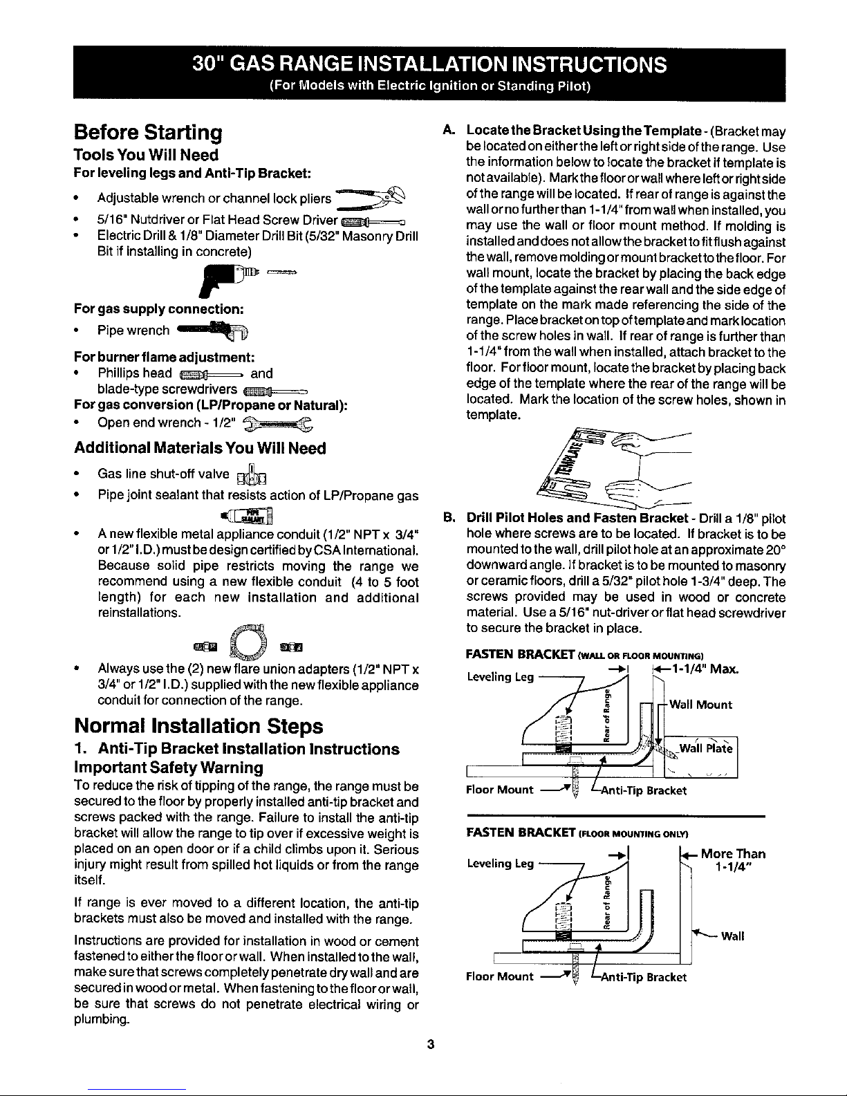
A.
B,
3
Locate the Bracket Using the Template- (Bracketmay
belocated oneithertheleftorrightsideofthe range. Use
the informationbelowtolocate thebracket if templateis
notavailable). Markthefloororwallwhereleftorrightside
ofthe range willbelocated. Ifrear ofrangeisagainstthe
wallornofurther than1-1/4"from wallwheninstalled,you
may use the wall or floor mount method. If moldingis
installedanddoes notallowthe bracketto fitflush against
thewall,removemoldingormount brackettithe floor. For
wall mount,locate the bracket byplacingthe backedge
ofthe templateagainst the rearwallandthe side edgeof
template on the mark made referencingthe sideof the
range.Placebracket ontopoftemplateandmarklocation
ofthe screwholesin wall. If rearof range isfurther than
1-1/4"fromthe wallwhen installed,attach bracketto the
floor. Forfloor mount,locate the bracketby placingback
edge of the template where the rear of the range will be
located. Markthe location of the screw holes,shownin
template.
Drill Pilot Holes and Fasten Bracket - Drilla 1/8" pilot
holewhere screws are to be located. Ifbracket isto be
mountedtothe wall, drillpilotholeat an approximate20°
downwardangle. Ifbracket istobe mountedtomasonry
orceramicfloors,drilla5/32" pilothole1-3/4"deep. The
screws provided may be used in wood or concrete
material. Use a 5/16" nut-driverorflat head screwdriver
tosecure the bracket in place.
FASTEN BRACKET (WALLORFLOORMOUNTING)
--I_1 1<--1-1/4" Max.
Levelinc
-Wall Mount
[
Floor Moun _Bracket
FASTEN BRACKET (FLOOR MOUNTING ONLY
Leveling Leg
I _ _ /
FIoorl Mount j_F_ Lnti-Tip Bracket
More Than
1-1/4"
"'-- Wall
Page 4

C. Level and Position Range- Level range byadjusting the
(4)levelinglegswithawrench.Note:A minimumclearance
of1/8"isrequiredbetweenthebottomoftherangeandthe
levelinglegtoallowroomfor thebracket.Usea spiritlevel
tocheckyouradjustments. Sliderange backinto position.
Visuallycheck that rearlevelingleg is inserted into and
fully securedby the Anti-Tip Bracketby removinglower
panelorstoragedrawer. Formodelswithawarmerdrawer
or broilercompartment, grasp the top rear edge of the
rangeand carefullyattempt totiltitforward.
2, Provide an adequate gas supply,
This unitisdesigned to operate on4" naturalgas or 10"LP/
Propanemanifoldpressure.Aconvertiblepressureregulator
is connected to the manifold and MUST be connected in
serieswiththegassupplylineregardlessofwhichtypeoffuel
isbeing used.
Care must betaken during installationof rangenottoobstruct
the flow of combustion and ventilation air.
For proper operation, the maximum inlet pressure to the
regulator should be no more than 14inches ofwater column
pressure. The inlet pressure tothe regulator must be at least
I inch greater than regulator manifold pressure. Examples: If
regulator is set for natural gas 4 inch manifold pressure, inlet
pressure must be at least 5 inches; if regulator has been
converted for LP/Propane gas 10inch manifoldpressure, inlet
pressure must be at least 11 inches.
Leaktestingofthe appliance shall beconductedaccording to
the instructions in step 4g.
The gas supply line should be 1/2" or 3/4" I.D.
Cen_erline
I of _ange [
lii '--iJ 11-1/2" _- •
I' L I.-7,_ I" RecommendedAreafor
• _.__..... I__ ._1 |] t20VOutletonRearof
_23'! _ i
, ...... | Walland AreaforThru
i , --- the Wall Connectionof
,, _ PipeStuband ShutOff
22',11
Valveis ShadedArea.
It I !119.
..fl J-;, ', : ..... i
I the FloorConnectionof
_PipeStubandShutOffValve.
3. Seal the openings.
Sealany openingsinthewall behindtherangeandinthefloor
under the range after gassupply line is installed.
4. Connect the range to the gas supply.
Topreventleaks, puta pipejointsealantonallmale (outside)
pipethreads.
Your regulator is in one of the two locations shown below.
Do not allow regulator to turn on pipe when
tightening fittings.
PressureRegulatorlocation
FrOnt i_t
to Regular_
Remove _k ParRI,
Storgar,_Or_*_e,_or
Warm_ Drawe_, Pn_,v'
(_e O_e,t_ Guide Re_lat_r
for In_,uttl_), location at
ff Equ_wped whh rear of
.__;r ....
4
Page 5

Gas connection for electric ignition models
Manual Flare Flexible FlareUnion Pressure
Shutoff Union Appliance Adaptor Regulator
Valve _ Conduit
off
Service Shut-Off Valve ElectricIgnition models only -_
(Shown in ON Position).
Besure lever is in the "On" position when
installation is complete
Gas connection for pilot models
Manual Flare Flexible FlareUnion Pressure
Shutoff Union Appliance Adaptor Regulator
Valve | Conduit
ON
a) Install an external manual gas shut-off valve togas supply
line in an easily-accessible location outside ofthe range.
Be sure you know how and where to shut-off the gas
supply to the range.
b) Install 1/2" flare union adapter to pressure regulator.
c) Attach appliance conduit to flare union on regulator.
d) Install flare union adapter to external manual shut-off
valve.
e) Attach appliance conduit to flare union on shut-off valve.
f) Make sure service shut-offvalve on pressure regulator is
in "ON" position.
g) Check for leaks. Turn the gas supply on to the range and
use a liquid leak detector at all joints and conduits to
check for leaks inthe system.
Do notuse a flame to checkfor gas leaks.
Checking Manifold Gas Pressure
Disconnect therangeand its individual shut-off valve from the
gas supplypiping systemduringany pressuretestingofthat
system at test pressures greater than 14"of water column
pressure(approximately1/2"psig).
The appliance must be isolated from the gas supply piping
system by closing itsindividual manual shut-off valve during
any pressure testing of the gas supply piping system at test
pressures equal to or less than 14" of water column prassu re
(approximately 1/2" psig).
Ifit should be necessary to check the manifold gas pressure,
connect manometer (watergauge) or other pressure device to
thetop burner right rearorifice. Usinga rubber hosewith inside
diameter of approximately 1/4," hold tubing down tight over
orifice. Turn burner valve on.
Foran accurate pressure check have atleast two(2)other top
burnersburning. Be surethe gas supply(inlet) pressureisat
leastone inchabove specifiedrangemanifoldpressure.The
gassupplypressureshouldneverbeover 14"water column.
Whenproperlyadjustedfor NaturalGasthe manifoldpressure
is4." (For LP/Propane Gas the manifoldpressureis 10.")
Read electrical connection details belowand
connect electricity to range.
Before servicing, disconnect electrical
supply at circuit breaker, fuse or power cord,
Electric Requirements: An individual, properly grounded and
poladzed branch circuit protected bya 15amp. circuit breaker
or time delay fuse. See serial plate for proper voltage.
Ext n i n ordPr c ti n :
Because of potentialsafety hazardsundercertain conditions,
we strongly recommend against the use of any extension
cord. However, ifyou still elect to use an extension cord, it is
absolutely necessary that it be a UL listed 3-wire grounding
type appliance extension cord and that the current carrying
rating ofthe cord in amperes be equivalent to or greater than
the branch circuit rating. Such extension cords are obtainable
through your local service organization.
PLEASE READ CAREFULLY! For personal
safety, this product must be properly grounded.
5
Page 6

Grounding Instructions
The power cord ofthis appliance is equippedwitha 3Iprong
(grounding)plugwhichmateswithastandard3-pronggrounding
wall receptacle to minimize the possibilityofelectricshock
hazard from thisappliance. The customershouldhave the
wall receptacle and circuitchecked bya qualifiedelectrician
tomakesurethereceptacle ispropedygroundedandpoladzed,
Preferred Method
Not, Under
Power Supply
Grounding Cord with
Type 3-Prong
Wall Grounding
Receptacle Plug
Where astandard two-prongwallreceptacle isencountered,
itisthepersonalresponsibilityandobligationofthecustomer
tohave itreplacedwitha properlygroundedthree-prong walt
receptacle.
DO NOT, UNDER ANY CIRCUMSTANCES, CUT OR
REMOVE THE THIRD (GROUND) PRONG FROM THE
POWER CORD.
This range is equipped with either an electric ignition
system or standing pilots. To determine which system
your range has, lift the cooktop. Models with standing
pilots will have pilot cups as pictured in step 6b. Follow
the appropriate instructions for your model.
Operation of Surface Burners
Venturi Style
Bar
6a. Electric Ignition Surface Burners
Operationof electricignitersshould be checkedafter range
and supply lineconnectorshave been carefullychecked for
leaks and range has been connected to electric power. To
checkfor properlighting,push in and turn a surface burner
knob to the LITE position. You willhear the igniter sparking.
The surface burner should lightwhen gas is available to the top
burner. Each burner should light within four (4) seconds in
normal operation after air has been purged from supply lines.
Visually check that burner has lit. Once the burner lights, the
control knob should be rotated out ofthe LITE position. There
are separate ignition devices for each burner. Try each knob
separately until all burner valves have been checked.
Note: Knob styles may varyfrom thosepictured below.
' I' /
J ''111
Knob Used KnobUsed
withTwo withLinear
PositionValve FlowValve
6b. Standing Pilot Surface Burners
After range and supply line conduits have been carefully
checkedfor leaks, purgeair from thesystem,The standing
pilotsmust be lit immediately,proceed as fellows:
1. Raise the cooktop.
2. Light both pilots with a match. When both pilots are lit,
adjust the top pilot adjustment until the pilots are
approximately 1/8"above the pilotcage witha veryslight
yellowtip.
Pilot
Cage
1/8" Above Pilot
t Cage
CheckSurface Burners
Tocheck for proper lighting, push in and turn asurface burner
knobtothe LITE position.Eachburnershouldlightwithinfour
(4) secondsinnormaloperation.Once theburnerlights,the
knob should be rotatedoutofthe LITE position. Tryeachknob
separately untilall burnervalveshave been checked.
Page 7

7. Air adjustment
The airshutter(adjustment)foreach ofthefourtopburnersis
located at the open end of the venturitube and setson the
hood of the valve,
Should the air shutter need adjusting, rotatethe air shutterto
allow more or lessair into the burner tubes as needed.
Adjustment
If the air is properly adjusted, the flame will be steady,
relatively quiet, and have approximately 1/2" sharp blue cone.
(Usually about the center of air shutter's ajustment.)
Ifthe flameisyellow in color, increaseairshutter openingsize.
Ifthe flame isa distinctblue, butliftingawayfrom the burner,
reducethe air shutter openingsize.
8. Adjust the "LOW" Setting of Linear Flow
Surface Burner Valve :
To
Sun'ace
Burner
Operation of Oven Burners and
Oven Adjustments
9a, Electric Ignition Burners
Operation of electric ignitersshould be checkedafter range
and supply lineconnectors have been carefully checked for
leaks and range has been connected to electric power.
The oven burner isequipped withan electric control system
as well as an electric oven burner igniter. If your model is
equipped with a waist-high broil burner, it will also have an
electric burner igniter. These control systems require no
adjustment. When the oven is set to operate, current willflow
to the igniter. It will "glow" similar to a light bulb. When the
igniter has reached a temperature sufficient to ignite gas,the
electrically controlled oven valve will open and flame will
appear atthe oven burner. There is atime lapsefrom 30 to 60
seconds after the thermostat isturned ON before the flame
appears at the oven burner. When the oven reaches the dial
setting, theglowing igniter will go off. The burner flame will go
"out" in 20 to 30 seconds after the ignitergoes "OFF." To
maintain any given oven temperature, thiscycle will continue
as long as the dial (or display) is set to operate.
After removing all packing materials and literature from the
oven:
a) Set oven to BAKE at 300-°F. See Owner's Guide for
operating instructions.
b) Within 60 seconds the oven burner should ignite. Check
forproper flame, andallowthe burnerto cycle once. Reset
controls to off.
c) If your model is equipped with a waist-high broiler, set
oven to BROIL. See Owner's Guide for operating
instructions.
d) Within 60 seconds the broil burner should ignite. Check
for proper flame. Reset controls to off.
a) Turn control to LITE until burner ignites.
b) ._ turn knob to LOWEST POSITION.
c) If burner goes out, readjust valve as follows:
Reset control to OFF. Remove the surface burner control
knob, insert a thin-bladed screw driver into the hollow valve
stem and engage the slotted screw inside. Flame size can be
increased or decreased with the turn of the screw. Adjust
flame until you can quickly turn knob from LITE to LOWEST
POSITION without extinguishing the flame. Flame should be
as small as possible without going out.
7
Page 8

9b. Standing Pilot Oven Burner
To lightthe oven pilot, proceed as follows:
Turn theoven thermostatknobto OFF. Remove oven bottom,
see step 10 for instructions on removing the oven bottom.
Light the oven pilot with a match. The oven pilot should burn
with astable flame after a few seconds operation and should
have asmall flame visible only at the opening inthe top ofthe
pilot assembly.
Turn oven thermostat knob to 300°F. The oven pilot should
nowbe larger with the flame extending down theslanted ramp
and burning against asmall metal bulb.
Primary Pilot Flame
Waist-High Burner
(SelfClean Models)
After 20-40 seconds, the main oven burner should ignite and
burn until the oven temperature has reached 300°F. At that
time, the oven pilot should get smaller, moving up
away from the metal bulb which will turn off the main oven
burner after20-40 seconds.
Secondary
Pilot Flame
The oven burner will continue to turn off and on to maintain
oven temperature.
10. Air Shutter-Oven Burner
The approximate flame lengthof the oven burner is 1 inch
(distinct inner, blue flame).
To determine ifthe oven burner flame is proper, remove the
oven bottom and burner baffle and set the oven to bake at
300OF.
To remove the oven bottom, remove oven hold down screws
at rear ofoven bottom. Pull upat rear, disengage front of oven
bottom from oven front frame, and pull theoven bottom out of
the oven. Remove burner baffle so that the burner flame can
be observe.
Iftheflame isyellow incolor, increaseairshutter opening size.
(See "2" in illustration below.) If the flame is a distinct blue,
reduce the air shutter opening size.
To adjust loosen lock screw (see "3" illustration below),
reposition air shutter, and tighten lock screw. Replace oven
bottom.
®
Air Shutter
Oven
Tube
®
Orifice
Hood
11. Air Shutter-Broil Burner (if equipped)
The approximateflame length of the broil burner is 1inch
(distinctinner,blue flame).
To determine ifthe broil burner flame is proper, set the oven
to broil.
Iftheflame isyellow incolor, increaseairshutter opening size
(see "2" in illustration.) If the flame is a distinct blue, reduce
the air shutter opening size.
To adjust, loosen lockscrew (see "3"inillustration), reposition
air shutter, and tighten lock screw.
8
Page 9

12. Make Sure Range is Level.
Leveltherange byplacingalevelhorizontallyonanovenrack.
Check diagonallyfrom frontto back, then levelthe range by
eitheradjustingthelevelinglegsor byplacingshimsunderthe
cornersofthe range as needed.
13. After installation is complete, make sure all
controls are left in the OFF position.
Model and Serial Number Location
The serial plate is located under the lift-up cooktop.
When ordering parts for or making inquiresabout yourrange,
always be sure to include the model and serial numbers and
a lot number or letter from the serial plate on your range.
Your serial plate also tells you the rating of the burners, the
type of fuel andthe pressure the rangewas adjusted for when
it left the factory.
Before You Call for Service
Check to make sure the housefuses or circuitbreakers for
yourrangeare notblownoropen. Refer totheAvoidService
Checklist and operating instructionsin yourOwner's Guide. it
may save you time and expense. The list includes common
occurrences that are not the result of detective workmanship
or materials in this appliance.
Refer to the warranty inyour Owner's Guide for our
toll-free service number and address. Please call or write
if you have inquiries about your range product and/or
need to order parts.
Care, Cleaning and Maintenance
Refer to the Owner's Guide for operating and cleaning
instructions.
Ifremovingthe range is necessaryfor cleaning ormaintenance,
shut offgas supply. Disconnect the gas and electrical supply.
If the gas or electrical supply is inaccessible, lift the unit
slightly at the front and pull out away from the wall. Pull only
as far as necessary to disconnect the gas and electrical
supply. Finish removing the unit for servicing and cleaning.
Reinstall in reverse order making sure to level the range and
check gasconnections for leaks. See Anti-Tip Instructions for
proper anchoring instructions.
Gas Conversion
This range was adjusted for Natural or LP/Propane gas, as
specified on the serial plate.
Your regulator is in one of the two locations shown.
Do not remove the Pressure Regulator.
Pressure Regulatorlocation
Fro_ A_C_SS
tn negu_ton
Remc_e _ck Pan_l,
St_gl_n_v_
_er Dra_,
for InSl_).
Eq_pped _th
la. Convert the Pressure Regulator
Self-Cleaning Electric Ignition Models
a. Unscrew the cap from the pressure regulator. Be sure
springstays in place.
b. Turnthecaptothedesiredsetting(see illustrationbelow).
c. Replacethecapoftheregulator.Theletterscorresponding
withthetype of gas being usedshould be visibleonthe
exposed end of the cap.
4 CAF_,
HOLLOWEND _ _
TOWARDS "_l I_ SOUD END
TOWARDS
REGULATOR _ REGULATORFOR NATURAL GAS _ FOR L.R GAS
lb.Convert the Pressure Regulator
Non Self-Cleaning Electric Ignition Models
a. Usinga screwdriverorcoin,turnthecapcounterclockwise
toreleasefromthepressure regulator.BesuretheO-ring
gasket stays in place.
b. Turnthecap overandplace intotheslots.Turnclockwise
tolock inposition.The letterscorrespondingwiththetype
ofgas beingused shouldbe visibleonthe exposedend
of the cap.
HOLLOW END ,. SOLID END
TOWARDS _11 d'CAP_I _ TOWARDS
REGULATOR _ _ REGULATOR
FOR NATURAL GAS _-J' FOR LP. GAS
,_ _I_O-RING GASKET
(DO NOT REMOVE)
SPRING
9
Page 10

lc. Convert the Pressure Regulator - Non-Self-
Cleaning Standing Pilot Models
a. Remove the cap fromthepressureregulator.
b. Remove the plunger fromthe cap.
c. Turn the plunger with the enlarged end down for LP/
Propaneuse.Turnthe plungerwiththesmall enddownfor
Natural gas use, (See illustrationbelow,)
d. Replace theplungerinsidethecap,
e. Replace the cap.
Q_ CAP
SMALL END _11( _ ENLARGED END
TOWARDS TOWARDS
REGULATOR FOR REGULATOR FOR
NATURAL GAS LR GAS
Oven/Broiler
-- Burner Spud
f.
Remove thethermostat knob toaccess the selector key.
Checkthe selector key on the thermostat to becertain the
pointer is turned to select the proper fuel being used
)lacethe thermostat knob.
Oven Gas Selector
Pipe
OFF NAT LP
2. Convert Surface Burner Valves -All Models
a. Liftand lock cooktoptogainaccesstothe surfaceburner
spuds. Surface burner spuds for models with venturi
burners are located in the front ofthe burner box. For
models withdualorsnap-inburners,the spudsare inthe
bottomofthe burnerbox,
b. Using1/2"wrench,adjustsurfaceburnerspudasfollows.
ForNaturalto LP/Propaneconversiontightenspuddown
clockwise until snug (approximately 2-1/2 turns). This
restrictsthe flow of gas throughthe spudsto onlythat
allowed by the hollow LP/Propane meteringpin.Do not
over tighten,
For LP/Propane to Natural conversion, loosen spuds
counter-clockwise (approximately 2-1/2 turns). This
increases the flow of gas around the metering pin.
NATURAL GAS Pl_SPUO,_,,
INCREASE GAS VOLUME
INCREASE FI_'M E SIZE : L,P, GAS
_&_ DECREASESGAS VOLUME
DECREASES FLAME SIZE
3. Convert Oven Burner Spud
a. Remove ovenbottom and oven burner baffle located on
top ofburner. To remove oven bottom, remove oven hold
down screws at rear of oven bottom. Pull up at rear,
disengage front to oven bottom from oven front-frame,
and pull the oven bottom straight outofthe oven. Remove
nut attaching burner baffle to oven burner.
b. Using 1/2" wrench, adjust oven burner spud as follows.
ForNatural to LP/Propane conversion tighten spuddown
clockwise until snug (approximately 2-1/2 turns). This
restricts the flow of gas through the spuds to only that
allowed by the hollow LP/Propane metering pin. Do not
over tighten.
,
a,
For LP/Propane to Natural conversion, loosen spuds
counter-clockwise (approximately 2-1/2 turns). This
increases the flow of gas around the metering pin.
Convert Broil Burner Spud (if equipped)
Using1/2"wrench,adjustbroilburnerspudasfollows.For
Natural to LP/Propane conversiontighten spud down
clockwise until snug (approximately 2-1/2 turns), This
restrictsthe flow of gas through the spudsto onlythat
allowedbythe hollowLP/Propane meteringpin.Do not
over tighten.
For LP/Propane to Natural conversion, loosen spuds
counter-clockwise (approximately 2-1/2 turns). This
increasesthe flow of gas around the metering pin.
After conversion is complete, follow normal instructions
on page 3 for installation and burner operation/
adjustments. For models with linear flow valves, the low
"simmer" setting must be adjusted after conversion.
10
 Loading...