

Page 1
ELECTRIC COOKTOP INSTALLATION INSTRUCTIONS
INSTALLATION AND SERVICE MUST BE PERFORMED BY A QUALIFIED INSTALLER.
IMPORTANT: SAVE FOR LOCAL ELECTRICAL INSPECTOR'S USE.
READ AND SAVE THESE INSTRUCTIONS FOR FUTURE REFERENCE.
WARNING
vapors and liquids in the vicinity of this or any other appliance.
FOR YOUR SAFETY: DO NOT store or use gasoline or other fl ammable
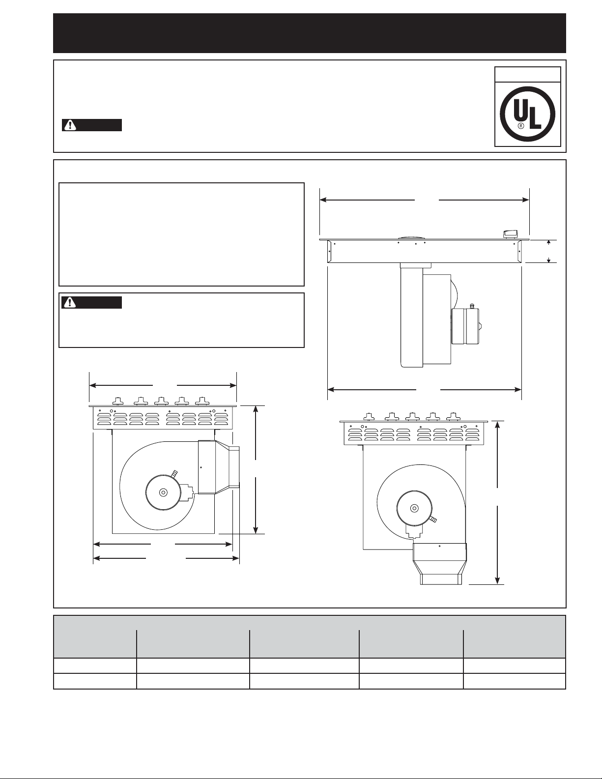
PRODUCT DIMENSIONS
IMPORT ANT INSTALLA TION INFORMA TION
• All electric cooktops run off a single phase,
three-wire or four-wire cable, 124/240 volt or
120/208 volt, 60 hertz, AC only electrical supply
with ground.
• Please note minimum distance between
cooktop and adjacent and overhead
unprotected cabinetry is 30" (76.2 cm).
WARNING
The corners of this unit are fragile.
Carefully install the cooktop by its sides. When
installing, never let the weight of the unit rest on
any one corner.
A
U.S.A.
(8.3 cm)
*
9
/
3
32"
B
18 19/32"
(47.9 cm)
D
21 11/16"
(55.1 cm)
Figure 1 - PRODUCT DIMENSIONS
PRODUCT DIMENSIONS
MODEL
30" Cooktop 30
36" Cooktop 36
A. GLASSTOP
WIDTH
¾" (78.1 cm) 22
¾" (93.4 cm) 22
All dimensions are in inches (cm).
* Allow 7" (17.8 cm) space below cooktop to clear the electric cable and allow for
installation of the junction box on the wall at the back of the cooktop.
Printed in U.S.A.
B. COOKTOP
DEPTH
1
/
16" (56.0 cm) 28
1
/
16" (56.0 cm) 34
1
C. CHASSIS
WIDTH
19
/
32" (72.6 cm) 20
7
/
32" (86.9 cm) 20
C
23 3/8"
(59.4 cm)
D. CHASSIS
DEPTH
27
/
32" (52.9 cm)
27
/
32" (52.9 cm)
P/N 318205430 (1304) Rev. A
Page 2

ELECTRIC COOKTOP INSTALLATION INSTRUCTIONS
Overhead
Cabinet Should
Not Exceed
a Maximum
Depth of 13"
(33 cm)
18" Min.
(45.7 cm)
24"
(61 cm)
E
1" (2.5 cm) Minimum Flat Distance
from Cutout Edge.
G
H
F
1" (2.5 cm) Min. Flat Area
From Cutout Edge.
30" (76.2 cm) Min.
Clearance Between
the Top of the
Cooking Platform
and the Bottom of an
Unprotected Wood or
Metal Cabinet.
24" (61 cm) Min. when
Bottom of Wood or
Metal Cabinet is
Protected by Not
Less Than 1/8" Flame
Retardant Millboard
Covered With Not Less
Than No. 28 MGS
F
Sheet Steel, 0.015"
(0.4 mm) Stainless
Steel, 0.024" (0.6 mm)
Aluminum or 0.020"
(0.5 mm) Copper.
Figure 2 – CABINET DESIGN
G. Cutout Width H. Cutout Depth
Tolerance -0" +⅛"
(0.3cm)
Tolerance -0" +⅛" (0.3cm)
MODEL
E. Top Cabinet
Minimum Side
Clearance
F. Minimum
Clearance from
Each Side
30" Cooktop 30" (76.2 cm) 9" (22.9 cm) 28 ⅞" (73.3 cm) 21 ⅛" (53.7 cm)
36" Cooktop 36" (91.4 cm) 9" (22.9 cm)
CAUTION
storage space located above the cooktop should be avoided. If cabinet storage is to be provided,
the risk can be reduced by installing a range hood that projects horizontally a minimum of 5 inches
beyond the bottom of the cabinets.
To eliminate the risk of burns or fi re from reaching over heated surfaces, cabinet
34 ½" (87.6 cm)
2
21 ⅛" (53.7 cm)
Page 3

ELECTRIC COOKTOP INSTALLATION INSTRUCTIONS
Important Notes to the Installer
1. Read all instructions contained in these installation
instructions before installing the cooktop.
2. Remove all packing material before connecting the
electrical supply to the cooktop.
3. Observe all governing codes and ordinances.
4. Be sure to leave these instructions with the
consumer.
Important Note to the Consumer
Keep these instructions with your Use and Care Guide
for future reference.
IMPORTANT SAFETY
INSTRUCTIONS
• Be sure your cooktop is installed and grounded
properly by a qualifi ed installer or service
technician.
• These cooktops must be electrically grounded in
accordance with local codes or, in their absence,
with the National Electrical Code ANSI/NFPA No.
70—latest edition in the United States.
is ever necessary.
3. A suitable strain relief must be provided to
attach the fl exible armored cable to the junction
box. Observe all governing codes and local
ordinances.
Serial Plate Location
Model and
Serial Plate
(Under Cooktop)
Figure 3
WARNING
must be shut off while line connections are being
made. Failure to do so could result in serious
injury or death.
The electrical power to the cooktop
Electrical Requirements
Observe all governing codes and local ordinances.
1. A 3-wire or 4-wire single phase 120/240 or 120/208
Volt, 60 Hz AC only electrical supply is required on
a separate circuit fused on both sides of the line. A
50A minimum time-delay fuse or circuit breaker is
needed. DO NOT fuse neutral.
NOTE: Wire sizes and connections must conform with
the fuse size and rating of the appliance in accordance
with the National Electrical Code ANSI/NFPA No.
70–latest edition.
WARNING
with this appliance. Such use may result in a fi re,
electrical shock, or other personal injury.
2. The appliance should be connected to the fused
disconnect (or circuit breaker) box through
fl exible armored or nonmetallic sheathed cable.
The fl exible armored cable extending from this
appliance should be connected directly to the
grounded junction box. The junction box should be
located as shown in Figure 4 with as much slack
as possible remaining in the cable between the box
and the appliance, so it can be moved if servicing
An extension cord must not be used
Required Tools for Installation
- Phillips Screwdriver
- ¼" Nut driver / Ratchet
7
/
-
16" Nut driver / Ratchet
Supplied Hardware
Qty. Description Used for
(4)
(2)
(4)
(8)
(2)
(4)
1/4-20 Nylon Insert
7/16" Hex Nut
#10-24 3.5"
Long Phillips Screw
#8-18 Wide Head
Phillips Screw
#8-18 Black
¼" Hex Head Screw
Hold Down Bracket
Plastic Access Hole Plug
Blower (fi g. 19)
Brackets
(fi g.15 & 16)
Transition Duct
(fi g. 20)
Plenum and Wire
Box (fi g. 17 & 21)
Countertop
(fi g. 15 & 16)
Plenum (fi g. 17)
3
Page 4

ELECTRIC COOKTOP INSTALLATION INSTRUCTIONS
1
Positioning the cooktop
The exhaust vent from the cooktop must be located
between wall studs or fl oor joists so that the ductwork
may be installed properly
2
Prepare Base Cabinet
This cooktop is designed to fi t easily into a variety
of cabinets. However, some cabinets may require
modifi cations.
2.1
Preparing a cabinet with drawers
If the cabinet has drawers, the drawers must be
removed and the drawer fronts attached to the front of
the cabinet.
2.2
Verify internal length and width of base
cabinet
In some cabinets, the sides or back wall may need to
be cut out, and the corner braces removed in order to
accommodate the unit.
2.3
Counter top cutout
Countertops with a rolled front edge and radius at the
base of the backsplash may not provide the fl at surface
area required to accommodate the cooktop.
Cut countertop opening according to the dimensions
shown in Figure 2 . The opening must be cut squarely
with sides parallel to each other, front and rear
perpendicular to the sides.
Provide Electrical Connection
2.4
Install the junction box under the cabinet within shaded
area shown in Figure 4 and run 120/240 or 120/208
Volt, AC wire from the main circuit panel.
NOTE: DO NOT connect the wire to the circuit panel
at this time. Wait until all wires have been connected in
the junction box.
4½"
(11.4cm)
6"
(15.2cm)
3
Preparing for Ductwork
Cut hole in cabinet wall or fl oor as appropriate for your
installation. Make sure exhaust duct is located between
wall studs or fl oor joists.
WARNING
DO NOT vent into a wall, ceiling, crawlspace, attic
or any concealed space.
WARNING
ceiling, DO NOT damage electrical wiring and other
hidden utilities.
The blower can be installed to exhaust down or to the
back. See Figure 5 or 6 for the location of the exhaust
outlet for bottom or rear discharge.
Ductwork MUST be vented to outside.
When cutting or drilling into wall or
DUCTWORK INSTALLATION DIMENSIONS
Model J. Right of Center
13
30" Model 1
36" Model 1
CUTOUT
CENTER
/
16" (4.6 cm)
3
/
16" (3.1 cm)
CUTOUT
CENTER
Figure 4 –
5½"
(14cm)
ELECTRICAL OUTLET INSTALL
DIMENSIONS
3 27/32”
(9.8 cm)
Figure 5 –
J
BOTTOM DUCTWORK HOLE
4
Page 5

ELECTRIC COOKTOP INSTALLATION INSTRUCTIONS
CUTOUT
CENTER
CUTOUT
CENTER
J
8 27/32"
(22.5 cm)
Kit 5304488297
For Left or Right Ducting
Figure 6 –
3.1
Alternate Ducting
For installations involving left or right exhaust
ductwork, a duct adapter kit 5304488297 is available.
See Figure 6B. Dimensions are shown in Figure 6A for
locating the duct cutout with this adapter kit.
CUTOUT
CENTER
BACK WALL DUCTWORK HOLE
Figure 6B –
3.2
Makeup Air
Local building codes may require the use of makeup
air systems. Consult local codes to determine specifi c
makeup air requirements for your installation.
Kit 316902492 is available to reduce airfl ow below
400CFM.
4
Blower to Ductwork Alignment
The use of fl exible ducting is discouraged because it
can severely restrict airfl ow. If the blower outlet and the
fl oor or wall duct location DO NOT align, then fl exible
METAL ducting can be used to adapt to an offset.
ALTERNATE DUCT TRANSITION KIT
6"
(15.2 cm)
Figure 6A –
3 ¾"
(9.5 cm)
22 ¾"
(57.8 cm)
ALTERNATE SIDE DUCTWORK HOLES
5
6" Max.
Center line
To Center
line Offset
Figure 7 –
DUCTWORK ALIGNMENT
Page 6

ELECTRIC COOKTOP INSTALLATION INSTRUCTIONS
5
Installing the Ductwork
Use galvanized or aluminum duct in 6” round or 31⁄4”
x 10" size, or a combination of both. PVC duct should
be used if installing under a poured concrete slab.
Use the shortest and straightest duct run possible.
For satisfactory performance, the duct run should
not exceed 100 feet equivalent length. Refer to the
“Calculating Duct Length” chart for equivalent lengths.
(see page 13).
NOTE: Local building code must be followed in
specifying approved type and schedule of ALL duct
used. Always use an appropriate roof or wall cap with
damper.
Duct Tape Over
Seam and Screw
Air Flow
Screw
Figure 8 – DUCT TAPE OVER SEAM AND
SCREW
Figure 10 –
DUCT THROUGH-THE-FLOOR
Figure 9 –
DUCT ON-THE-FLOOR
Figure 11 –
DUCT THROUGH-THE-WALL
6
Page 7

ELECTRIC COOKTOP INSTALLATION INSTRUCTIONS
6
Installing the cooktop into countertop
Lift the cooktop by the glass side edges as shown
Figure 12.
CAUTION
to lift or move the cooktop into position – glass
breakage may occur (Figure 13).
Lower the cooktop into the countertop opening, guiding
it into position. Glass is fragile—DO NOT allow it to
drop onto the countertop. Support from the underside
and lower slowly. Carefully remove your fi ngers one
corner at a time to lower the cooktop into position.
DO NOT use the glass top vent opening
Check for glass fl atness to the countertop. Verify that
the cutout is sized properly, that nothing is between
the glass and the countertop, and that no parts of the
burner box are binding or caught on the countertop.
Check for Visual Gap
Figure 14 –
CHECK FOR FLATNESS
NOTE: DO NOT use Silicone RTV or caulk
to seal the cooktop glass to the
countertop.
Figure 12 – HANDLE THE COOKTOP BY THE
EDGES
Figure 13 – DO NOT HANDLE THE COOKTOP
BY THE VENT OPENING
7
Page 8

ELECTRIC COOKTOP INSTALLATION INSTRUCTIONS
7
Installing the installation brackets
Remove the two screws in the bottom of the cooktop
near the center of each of the ends. Use the two
screws to attach the hold down brackets to the bottom
of the cooktop. Insert the screw into the bracket until
it contacts the backside of the countertop, to prevent
damage to the countertop, DO NOT over tighten the
screw. Figure 15 & 16.
Two #8-18 Black Hex
Head Screws Attached to
Cooktop
Figure 15 –
ATTACH THE TWO BRACKETS
One Long
Phillips Screw
One Hold
Down
Bracket
8
Installing the blower plenum to the
cooktop
With the blower opening on the right slide the plenum
into the opening in the bottom of the cooktop.
Push up on the plenum until the mounting rails on the
sides of the plenum contact the bottom of the cooktop.
Install six #8-18 hex head screws, two in each of the
front and rear fl anges, two in the side fl ange, to hold
the plenum in place.
Six #8-18 Black
Hex Head Screw
Cooktop
Screws
Supplied with
Cooktop
Figure 16 –
Countertop
Phillips
Screw
SECURE COOKTOP TO COUNTERTOP
Figure 17 –
ATTACH PLENUM TO THE COOKTOP
8
Page 9

ELECTRIC COOKTOP INSTALLATION INSTRUCTIONS
Insert 4 plastic access hole plugs from the
9
Installing the blower to the plenum
9.1
Attach the transition to the outlet of the blower
using four screws. Tape the joint to seal.
One Screw per Side.
#8-18 Wide Head Phillips Screws
9.2
outside of the plenum to seal the access holes.
1/4-20
Nylon
Insert
Nut
Access hole
plugs
Figure 18 –
ATTACH TRANSITION TO THE
BLOWER
Figure 19 –
9.3
Install four nylon insert nuts to the studs on the
blower, fi nger tighten until resistance is felt. Position
the blower discharge opening to match the ductwork.
Slide the nuts on the side of the blower housing into
the four keyhole openings on the side of the plenum
and allow to slide down into the slots. Using a nut
driver or ratchet through the 4 access holes in the left
side of the plenum tighten the nuts.
Plastic
plugs
NUT LOCATIONS INSIDE THE PLENUM
Key Slot
Mounting
Holes
Figure 20 –
9
ATTACH BLOWER TO THE PLENUM
Page 10

ELECTRIC COOKTOP INSTALLATION INSTRUCTIONS
10
Blower electrical connection
Connect the 5-pin plug on the blower assembly to
the matching 5-pin receptacle on the bottom of the
cooktop, making sure to engage the locking tabs on
the connectors.
Fold all wires into the wire box on the end of the blower
conduit. Fasten the wire box to the cooktop with two
#8-18 making sure that no wires are trapped.
12
Electrical connections
Note to Electrician: The insulation of the power
leads supplied with this appliance are UL-recognized
for temperatures much higher than the temperature
rating of household wiring. DO NOT replace the wires
in the conduit with household wiring.
Aluminum Wiring
WARNING
IMPROPER CONNECTION OF
ALUMINUM HOUSE WIRING TO THE COPPER
LEADS CAN RESULT IN SERIOUS PROBLEMS.
Attach copper wires to aluminum wiring using special
connectors designed and UL-listed for joining copper
to aluminum. Follow the connector manufacturer’s
recommended procedure closely.
It is the responsibility and obligation of the consumer to
contact a qualifi ed installer to assure that the electrical
installation is adequate and is in conformance with
the National Electrical Code ANSI/NFPA No. 70latest edition, or with CSA Standard C22.1, Canadian
Electrical Code, Part 1, and local codes and
ordinances.
Figure 21 –
11
Connecting the ductwork
Connect the ductwork prepared in Steps 4 and 5 to the
blower transition duct.
CONNECT BLOWER TO COOKTOP
WARNING
heed this warning may result in electrocution or
other serious injury.) This appliance is equipped
with copper lead wire. If connection is made to
aluminum house wiring, use only connectors that
are approved for joining copper and aluminum wire
in accordance with the National Electrical Code
and local code and ordinances. When installing
connectors having screws which bear directly on
the steel and/or aluminum fl exible conduit, do no
tighten screws suffi ciently to damage the fl exible
conduit. DO NOT over bend or excessively distort
fl exible conduit to avoid separation of convolutions
and exposure of internal wires.
DO NOT ground to a gas supply pipe. DO NOT
connect to electrical power supply until appliance
is permanently grounded. Connect the ground wire
before turning on the power.
Risk of electrical shock (Failure to
10
Page 11

ELECTRIC COOKTOP INSTALLATION INSTRUCTIONS
WARNING
(If your appliance is equipped with a
white neutral conductor.)
This appliance is manufactured with a white neutral
power supply and a frame connected copper
wire. The frame is grounded by connection of
grounding lead to neutral lead at the termination
of the conduit, if used in USA, in a new branch
circuit installation (1996 NEC), mobile home,
recreational vehicles, where local code DO NOT
permit grounding trough the neutral (white) wire
or in Canada, disconnect the white and green lead
from each other and use ground lead to ground
unit in accordance with local codes, connect
neutral lead to branch circuit-neutral conductor
in usual manner see Figure 23. If your appliance
is to be connected to a 3 wire grounded junction
box (US only), where local code permit connecting
the appliance-grounding conductor to the neutral
(white) see Figure 22.
NOTE TO ELECTRICIAN: The armored cable leads
supplied with the appliance are UL-recognized for
connection to larger gauge household wiring. The
insulation of the leads is rated at temperatures much
higher than temperature rating of household wiring.
The current carrying capacity of the conductor is
governed by the temperature rating of the insulation
around the wire, rather than the wire gauge alone.
Where local codes permit connecting the
appliance-grounding conductor to the neutral
(white) wire:
If your cooktop has a 4-wire cable to be connected
to a 3-wire grounded junction box (see fi gure 22):
1. Disconnect the power supply.
2. In the circuit breaker, fuse box or junction box:
connect appliance and power supply cable wires as
shown in fi gure 22.
Cable from Power Supply
If the appliance is used in a new branch circuit
installation (1996 NEC), mobile home, recreational
vehicle, or where local codes DO NOT permit
grounding through the neutral (white) wire, the
appliance frame MUST NOT be connected to the
neutral wire of the 4-wire electrical system.
If your cooktop has a 4 wire cable (see fi gure 23):
1. Disconnect the power supply.
2. Separate the green (or bare copper) and white
appliance cable wires.
3. In the circuit breaker, fuse box or junction box:
connect appliance and power supply cable wires as
shown in fi gure 23.
Cable from Power Supply
Ground Wire
White
Red
Wires
Ground Wire
(Bare or Green
Wire)
Junction Box
U.L.-Listed Conduit
Connector (or CSA listed)
Cable from appliance
Wires
Black
Wires
Figure 23 - 4 WIRE GROUNDED JUNCTION BOX
WARNING
If connecting to a 4-wire power
supply cable electrical system, the appliance frame
connected ground wire MUST NOT be connected to
the neutral wire of the 4-wire electrical system.
White Wire
(Neutral)
Red
Wires
Ground Wire
(Bare or Green Wire)
U.L.-Listed Conduit
Connector (or CSA listed)
Cable from appliance
Black
Wires
Junction
Box
White Wire
(Neutral)
Figure 22 - 3 WIRE GROUNDED JUNCTION BOX
11
Page 12

ELECTRIC COOKTOP INSTALLATION INSTRUCTIONS
Install Grease Filter and Grate
13
DO NOT operate the vent without the grease fi lter in place.
• Place the grease fi lter diagonally through the vent
opening.
• Make sure it rests, at an angle, on the supports in the
vent opening.
Grease Filter
Vent Chamber
Vent Opening Top
Grease Filter
• Carefully place the vent grate onto the opening.
Place the side of the vent marked FRONT towards
the front of the opening. The vent grate will only fi t
one way, DO NOT force into the opening.
Match Curve on
“FRONT” Mark
Figure 25 –
INSTALL THE VENT GRATE
Vent Grate with
Curve in Glass
Checking Operation
Refer to the Use and Care Guide for operation.
CAUTION
elements. They may be hot enough to burn you.
DO NOT touch cooktop glass or
Model and Serial Number Location
The serial plate is located under the cooktop (see Fig.
3).
When ordering parts for or making inquiries about
your cooktop, always be sure to include the model and
serial numbers from the serial plate on your cooktop.
Figure 24 –
GREASE FILTER LOCATION
Before You Call for Service
Read the Before You Call for Service Checklist and
operating instructions in your Use and Care Guide.
It may save you time and expense. The list includes
common occurrences that are not the result of
defective workmanship or materials in this appliance.
12
Page 13

ELECTRIC COOKTOP INSTALLATION INSTRUCTIONS
Calculating Duct Length Table
For maximum effi ciency, use the shortest and straightest duct possible. Use as few fi ttings as
possible. For best performance, the duct run should not exceed 100 feet of equivalent length.
Calculations are approximate and based on HVAC industry standards.
DUCT PIECES
6" (15.2cm) Round
Straight **
6" (15.2cm) Round Metal Flex
No Bends **
6" (15.2cm)
90° Elbow
6" (15.2cm)
45° Elbow
3¼" x 10" (8.2cm x 25.4cm)
Straight **
3¼" x 10" (8.2cm x 25.4cm)
90° Elbow
3¼" x 10" (8.2cm x 25.4cm)
45° Elbow
3¼" x 10" (8.2cm x 25.4cm)
90° Flat Elbow
EQUIVALENT
LENGTH X
1 Ft. (0.3m) Ft. or m
1.5 Ft. (0.45m) Ft. or m
10 Ft. (3m) Ft. or m
5 Ft. (1.5m) Ft. or m
1 Ft. (0.3m) Ft. or m
10 Ft. (3m) Ft. or m
5 Ft. (1.5m) Ft. or m
10 Ft. (3m) Ft. or m
NUMBER
USED =
EQUIVALENT
LENGTH
3¼" x 10" (8.2cm x 25.4cm) to 6"
(15.2cm) Round Transition 90°
Elbow
6" (15.2cm) Round to 3¼" x 10"
(8.2cm x 25.4cm) Transition
90° Elbow
3¼" x 10" (8.2cm x 25.4cm) to 6"
(15.2cm) Round Transition
6" (15.2cm) Round to 3¼" x 10"
(8.2cm x 25.4cm) Transition
6" (15.2cm) Round Wall Cap with
Damper
3¼" x 10" (8.2cm x 25.4cm) Wall
Cap with Damper
6" (15.2cm) Round Roof Cap 30 Ft. (9m) Ft. or m
** For Straight Round / Rectangular Duct, measure actual linear
feet used and then multiply by Equivalent Length shown.
30 Ft. (9m) Ft. or m
30 Ft. (9m) Ft. or m
5 Ft. (1.5m) Ft. or m
5 Ft. (1.5m) Ft. or m
30 Ft. (9m) Ft. or m
30 Ft. (9m) Ft. or m
TOTAL DUCTWORK Ft. or m
13
Page 14

NOTES
14
Page 15

NOTES
15
Page 16

NOTES
16
 Loading...