

Page 1

GAS COOKTOP INSTALLATION INSTRUCTIONS
INSTALLATION AND SER VICE MUST BE PERFORMED BY A QUALIFIED INSTALLER.
IMPORTANT: SA VE FOR LOCAL ELECTRICAL INSPECT OR'S USE.
READ AND SAVE THESE INSTRUCTIONS FOR FUTURE REFERENCE.
WARNING
If the information in this manual is not followed
exactly, a fire or explosion may result causing property
damage, personal injury or death.
FOR YOUR SAFETY:
— DO NOT store or use gasoline or other fl ammable vapors
and liquids in the vicinity of this or any other appliance.
— WHAT TO DO IF YOU SMELL GAS:
• DO NOT try to light any appliance.
• DO NOT touch any electrical switch; DO NOT use any
phone in your building.
• Immediately call your gas supplier from a neighbor's phone.
Follow the gas supplier's instructions.
• If you cannot reach your gas supplier, call the fi re department.
— Installation and service must be performed by a qualifi ed
installer, service agency or the gas supplier.
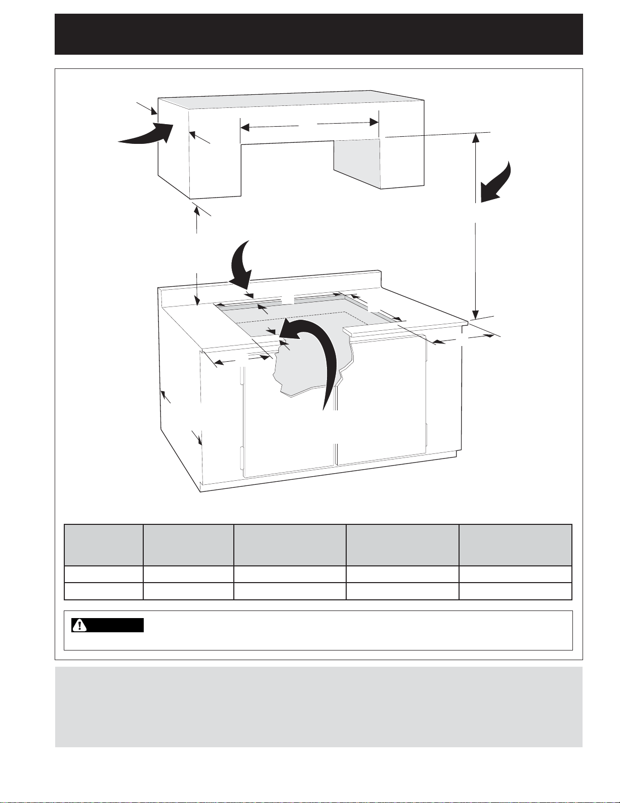
PRODUCT DIMENSIONS
A
A
1
20 1/8”
/
20
8"
51.1 cm
(51.1 cm)
Appliances Installed
in the state of
Massachusetts:
This Appliance can only
be installed in the state
of Massachusetts by a
Massachusetts licensed
plumber or gas fi tter.
This appliance must be
installed with a three (3)
foot / 36 in. long fl exible
gas connector. A "T"
handle type manual gas
valve must be installed
in the gas supply line to
this appliance.
3
23 3/8”
/
23
8"
59.4 cm
(59.4 cm)
C
C
PRODUCT DIMENSIONS
MODEL
A. COOKTOP
WIDTH
30" Gas Cooktop 30" (76.2 cm) 21
36" Gas Cooktop 36" (91.4 cm) 21
All dimensions are stated in inches and (cm).
Printed in U.S.A.
B
B
D
D
B. COOKTOP
DEPTH
13
/
32" (54.4 cm) 26
23
/
32" (55.1 cm) 32
11
/
3 11/16”
3
16"
9.4 cm
(9.4 cm)
13
17 13/16”
/
17
16"
45.2 cm
(45.2 cm)
C. CHASSIS
WIDTH
13
/
16" (68.1 cm) 18
11
/
16" (83.0 cm) 18
318205457 (0613) Rev. B
Figure 1
D. CHASSIS
DEPTH
15
/
16" (48.1 cm)
15
/
16" (48.1 cm)
Page 2
GAS COOKTOP INSTALLATION INSTRUCTIONS
Important Notes to the Installer
1. Read all instructions contained in these
installation instructions before installing
the cooktop.
2. Remove all packing material before
connecting the electrical supply to the
cooktop.
3. Observe all governing codes and
ordinances.
4. Be sure to leave these instructions with
the consumer.
5. Note: For operation at 2000 ft. elevations
above see level, appliance rating shall be
reduced by 4 percent for each additional
1000 ft.
Important Note to the Consumer
Keep these instructions with your Use and
Care Guide for future reference.
IMPORTANT SAFETY
INSTRUCTIONS
Installation of this cooktop must conform
with local codes or, in the absence of
local codes, with the National Fuel Gas
Code ANSI Z223.1/NFPA 54 in the
United States, or in Canada, with the
Canadian Fuel Gas Code, CAN/CGA
B149 and CAN/CGA B149.2.
• When installed in a manufactured
(mobile) home installation must
conform with the Manufactured Home
Construction and Safety Standard,
title 24 CFR, part 3280 [Formerly the
Federal Standard for Mobile Home
Construction and Safety, title 24, HUD
(part 280)] or, when such standard
is not applicable, the Standard for
Manufactured Home Installation, ANSI/
NCSBCS A225.1 or with local codes
where applicable.
This cooktop has been design certifi ed
by Underwriters Laboratories (UL).
As with any appliance using gas and
generating heat, there are certain safety
precautions you should follow. You will
fi nd them in the Use and Care Guide,
read it carefully.
• Be sure your cooktop is installed
and grounded properly by a
qualifi ed installer or service
technician.
• This cooktop must be electrically
grounded in accordance with local
codes or, in their absence, with
the National Electrical Code ANSI/
NFPA No. 70—latest edition in the
United States, or in Canada, with
the Canadian Electrical Code, CSA
C22.1 Part 1.
• The burners can be lit manually
during an electrical power outage.
To light a burner, hold a lit match to
the burner head, then slowly turn
the Surface Control knob to LITE.
Use caution when lighting burners
manually.
DO NOT store items of
interest to children in cabinets
above the cooktop. Children could be
seriously burned climbing on the cooktop
to reach items.
• To eliminate the need to reach over
the surface burners, cabinet storage
space above the burners should be
avoided.
• Adjust surface burner fl ame size so
it does not extend beyond the edge
of the cooking utensil. Excessive
fl ame is hazardous.
Never use your cooktop
for warming or heating the room.
Prolonged use of the cooktop without
adequate ventilation can be hazardous.
Storage on Appliance.
Flammable materials should not
be stored near surface units. This
includes paper, plastic and cloth items,
such as cookbooks, plasticware and
towels, as well as fl ammable liquids.
DO NOT store explosives, such as
aerosol cans, on or near the appliance.
Flammable materials may explode and
result in fi re or property damage.
WARNING
the cooktop must be shut off while
gas line connections are being
made. Failure to do so could result in
2
serious injury or death.
The electrical power to
Page 3
13" (33 cm)
Max. Depth
For Cabinet
Installed
Above
Cooktop.
GAS COOKTOP INSTALLATION INSTRUCTIONS
30" (76.2 cm)
Min. Clearance
Between the Top
of the Cooking
E
Clearance
Platform and
Unprotected
Wood or Metal
Cabinet
18" Min.
(45.7 cm)
24" Min.
(61 cm)
1 ⅜" (3.5 cm) Minimum Flat
Distance from Cutout Edge.
G
H
F
1 ⅜" (3.5 cm) Minimum Flat
Distance from Cutout Edge.
Figure 2 – CABINET DESIGN
F
E. Top Cabinet
MODEL
30" Cooktop 30" (76.2 cm) 9" (22.9 cm) 28" (71.1 cm) 19 ⅛" (48.6 cm)
36" Cooktop 36" (91.4 cm) 9" (22.9 cm)
CAUTION
cabinet storage space located above the cooktop should be avoided.
* For installations involving replacing an existing
cooktop, the cutout depth (H) in the countertop
may be larger than the above recommendation.
A Gap Filller Trim Kit is available which will then
allow for a maximum cutout depth (H) of 21 3/16".
Minimum Side
Clearance
To eliminate the risk of burns or fi re from reaching over heated surfaces,
F. Minimum
Clearance from
Each Side
The Gap Filler Trim Kit part number is
5304488403.
Before beginning installation, refer to the
instructions included with Gap Filler Trim Kit
5304488403 for countertop dimensions, cutout
limitations, and proper location of ductwork.
3
G. Cutout Width
± 1/16" (0.2 cm)
34" (86.4 cm)
H. Cutout Depth
± 1/16" (0.2 cm)
19 ⅛" (48.6 cm)
Page 4
GAS COOKTOP INSTALLATION INSTRUCTIONS
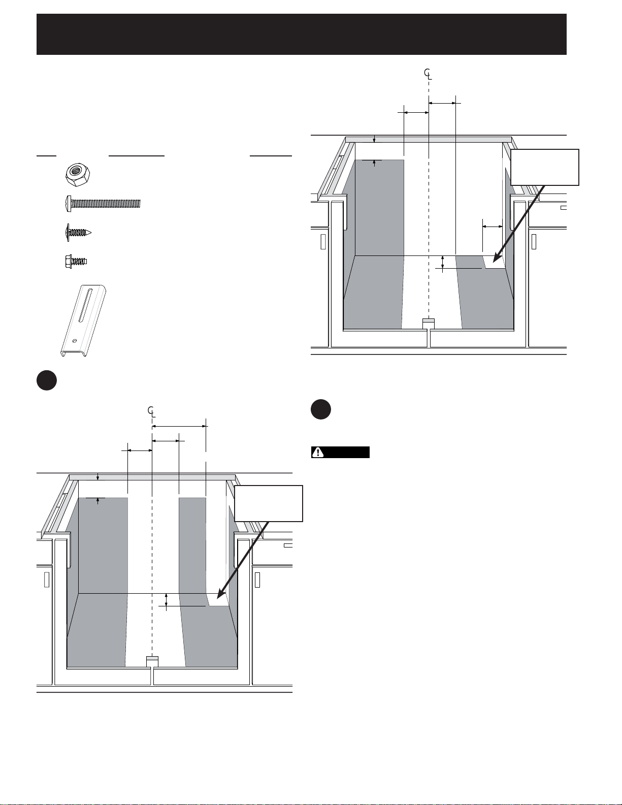
Required Tools for Installation
- Phillips Screwdriver
- ¼" Nut driver / Ratchet
7
/
16" Nut driver / Ratchet
-
Supplied Hardware
Qty. Description Used for
(4)
(2)
(4)
1/4-20 Nylon Insert
7/16" Hex Nut
#10-24 3.5"
Long Phillips
Screw
#8-18 Wide Head
Phillips Screw
Blower (fi g. 20)
Brackets
(fi g. 15 & 16)
Transition Duct
(fi g. 18)
3 1/4”
(8.3 cm)
5 1/2”
(13.9 cm)
11”
(27.9 cm)
Recommended
Gas Supply
Stub Area
4”
(10.2 cm)
(6)
#8-18 Black
¼" Hex Head Screw
Plenum and
Wire Box (fi g.
17 & 21)
(2)
Wall Outlet Location
1
Hold Down Bracket
Countertop
(fi g. 15 & 16)
Install the electric wall outlet within the shaded
area.
11 1/2”
(29.2 cm)
6”
(15.2 cm)
5 1/2”
(13.9 cm)
8 3/4”
(22.2 cm)
Recommended
Gas Supply
Stub Area
4”
(10.2 cm)
4”
(10.2 cm)
Figure 3B - 30” MODEL
ELECTRICAL OUTLET INSTALL DIMENSIONS
2
Provide an Adequate Gas Supply
This cooktop is designed to operate on natural
gas at 4" of manifold pressure only.
WARNING
connected in series with the manifold on the
cooktop and must remain in series with the supply
line.
For proper operation, the maximum inlet
pressure to the regulator must be no more than
14" of water column (W.C.) pressure.
For checking the regulator, the inlet pressure
must be at least 1" (or 2.5 kPa) greater than the
regulator manifold pressure setting. The regulator
is set for 4" of manifold pressure, the inlet
pressure must be at least 5".
The gas supply line to the range should be 1/2" or
3/4" pipe.
A pressure regulator must be
Figure 3A - 36” MODEL
ELECTRICAL OUTLET INSTALL DIMENSIONS
4
Page 5
GAS COOKTOP INSTALLATION INSTRUCTIONS
LP/Propane Gas Conversion
3
This appliance can be used with Natural gas or
LP/Propane gas. It is shipped from the factory for
use with natural gas.
A kit for converting to LP gas is supplied with your
cooktop. The kit is marked "FOR LP/PROPANE
GAS CONVERSION".
The conversion must be performed by a
qualifi ed service technician in accordance with
the kit instructions and all local codes and
requirements. Failure to follow instructions could
result in serious injury or property damage. The
qualifi ed agency performing this work assumes
responsibility for the conversion.
WARNING
conversion can result in serious personal injury
and property damage.
NOTE: Purchase a new fl exible line. DO NOT
USE AN OLD PREVIOUSLY USED LINE.
Important: Remove all packing material and
literature from cooktop before connecting gas and
electrical supply to cooktop.
Model and Serial Number
4
Failure to make the appropriate
Location
The serial plate is located on the underside of the
cooktop.
The wall receptacle and circuit should be checked
by a qualifi ed electrician to make sure the
receptacle is properly grounded.
Where a standard 2-prong wall receptacle is
installed, it is the personal responsibility and
obligation of the consumer to have it replaced by
a properly grounded 3-prong wall receptacle.
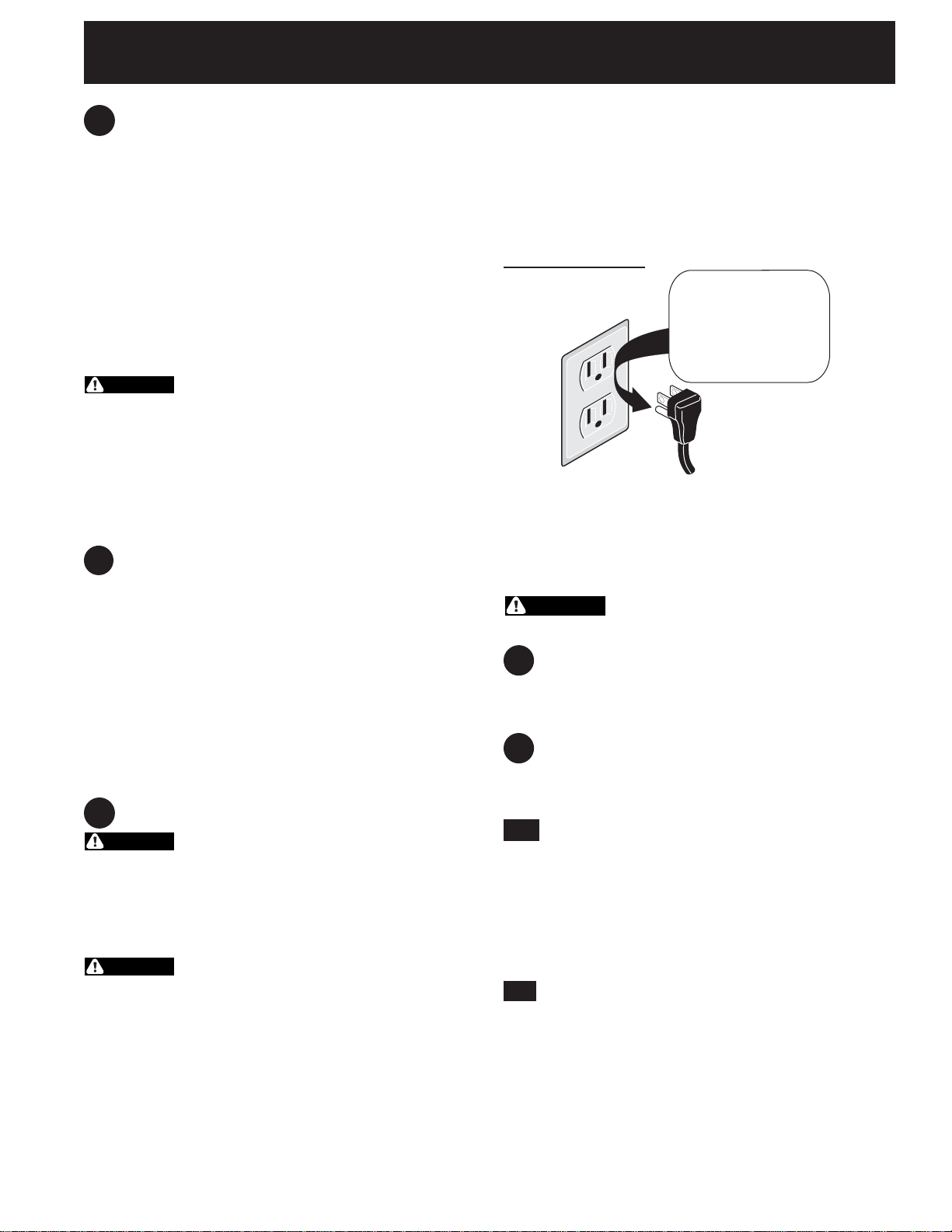
Preferred Method
DO NOT,
Grounding type
wall receptacle
DO NOT, under any circumstances, cut or
remove the third (ground) prong from the
power cord.
WARNING
from wall receptacle before servicing cooktop.
Disconnect electrical supply cord
under any
circumstances,
cut, remove,
or bypass the
grounding prong.
Power supply
cord with 3-prong
grounding plug.
Figure 4
When ordering parts for or making inquires about
your cooktop, always be sure to include the model
and serial numbers and a lot number or letter from
the serial plate of your cooktop.
Your serial plate also tells you the rating of the
burners, the type of fuel and the pressure the
cooktop was adjusted for when it left the factory.
5
Electrical Requirements
WARNING
branch circuit protected by a 15 amp circuit
breaker or time delay fuse. DO NOT use an
extension cord with this cooktop.
120 volt, 60 Hertz, properly grounded
Grounding Instructions
IMPORTANT Please read carefully.
WARNING
must be properly grounded.
The power cord of this appliance is equipped with
a 3-prong (grounding) plug which mates with a
standard 3-prong grounding wall receptacle (see
Figure 4) to minimize the possibility of electric
shock hazard from the appliance.
For personal safety, this appliance
Positioning the Cooktop
6
The exhaust vent from the cooktop must be
located between wall studs or fl oor joists so that
the ductwork may be installed properly
7
Prepare Base Cabinet
This cooktop is designed to fi t easily into a variety
of cabinets. However, some cabinets may require
modifi cations.
7.1
Preparing a Cabinet with Drawers
If the cabinet has drawers, the drawers must be
removed and the drawer fronts attached to the
front of the cabinet.
Verify internal length and width of base cabinet
In some cabinets, the sides or back wall may
need to be cut out, and the corner braces
removed in order to accommodate the unit.
7.2
Countertop Cutout
Countertops with a rolled front edge and radius at
the base of the backsplash may not provide the
fl at surface area required to accommodate the
cooktop.
Cut countertop opening according to the
dimensions shown in Figure 2. The opening must
be cut squarely with sides parallel to each other,
front and rear perpendicular to the sides.
5
Page 6

GAS COOKTOP INSTALLATION INSTRUCTIONS
8
Installing the Ductwork
Use galvanized or aluminum duct in 6” round
or 3¼” x 10" size, or a combination of both.
PVC duct should be used if installing under a
poured concrete slab. Use the shortest and
straightest duct run possible. For satisfactory
performance, the duct run should not exceed 100
feet equivalent length. Refer to the “Calculating
Duct Length” chart for equivalent lengths. (see
page 14). All duct joints should be fastened with a
screw and sealed with tape as shown in Figure 5.
NOTE: Local building code must be followed in
specifying approved type and schedule of ALL
duct used. Always use an appropriate roof or wall
cap with damper.
Duct Tape
Over Seam
and Screw
Air Flow
Screw
Figure 5 – DUCT T APE OVER SEAM AND SCREW
Figure 7 –
Figure 8 –
DUCT THROUGH-THE-FLOOR
DUCT THROUGH-THE-WALL
Figure 6 –
DUCT ON-THE-FLOOR
6
Page 7

GAS COOKTOP INSTALLATION INSTRUCTIONS
Preparing for Ductwork
9
Cut hole in cabinet wall or fl oor as appropriate
for your installation. Make sure exhaust duct is
located between wall studs or fl oor joists. Figure
9, 10, 11 & 12.
NOTE: Ductwork MUST be vented to outside. DO
NOT vent into a wall, ceiling, crawlspace, attic or
any concealed space.
WARNING
ceiling, DO NOT damage electrical wiring and
other hidden utilities.
When cutting or drilling into wall or
CUTOUT
CENTER
CUTOUT
CENTER
CUTOUT
CENTER
CUTOUT
CENTER
1/4"
¼" (0.6cm)
7
4 7/16"
/
4
16" (11.3cm)
5
/
4
16" (11.0cm)
7
Figure 9 – 30" MODEL
BOTTOM DUCTWORK HOLE
CUTOUT
CENTER
CUTOUT
CENTER
5
/
4
16" (11.0cm)
1
/
8" (18.1cm)
8" (20.3cm)
Figure 11 – 36" MODEL
BOTTOM DUCTWORK HOLE
CUTOUT
CENTER
CUTOUT
CENTER
¼" (0.6cm)
1/4"
15
16 15/16"
/
16
16" (43.0cm)
1/4"
¼" (0.6cm)
Figure 12 – 36" MODEL
LEFT OR RIGHT DUCTWORK HOLE
1
/
8
16"
8 1/16"
(20.5cm)
Figure 10 – 30" MODEL
BACK WALL
DUCTWORK HOLE
7
Page 8

GAS COOKTOP INSTALLATION INSTRUCTIONS
Alternate Ducting
9.1
For installations involving
space restrictions for orienting
the blower to connect to the
ductwork a duct adapter, Kit
5304488297 is available.
Dimensions are shown for
locating the duct cutout with
this adapter kit.
CUTOUT
CENTER
(16.2cm)
6"
5
/
22
8"
(57.5cm)
(15.2cm)
Figure 13
ALTERNATE DUCT
TRANSITION KIT
3
/
8"
6
Makeup Air
9.2
Local building codes may require the use of
makeup air systems. Consult local codes to
determine specifi c makeup air requirements for
your installation.
10
Blower to Ductwork Alignment
The use of fl exible ducting is discouraged
because it can severely restrict airfl ow. If the
blower outlet and the fl oor or wall duct location
DO NOT align, then fl exible METAL ducting can
be used to adapt to an offset.
6" MAX.
Center line
To Center
line Offset
Figure 13A - 30" MODEL
ALTERNATE DUCTWORK HOLE
CUTOUT
CENTER
(22.5cm)
1
/
16
8"
(41cm)
1
/
10
8"
(25.7cm)
1
/
8"
10
(25.7cm)
5
/
8"
3
(9.2cm)
(57.5cm)
6"
(15.2cm)
Figure 13B - 36" MODEL
ALTERNATE DUCTWORK HOLE
8
22
Figure 14 –
7
/
8"
5
/
8"
8
DUCTWORK ALIGNMENT
Page 9

GAS COOKTOP INSTALLATION INSTRUCTIONS
11
Installing the Cooktop
Lift the cooktop by the side edges as shown.
Lower the cooktop into the countertop opening,
guiding it into position. Support the underside and
lower slowly. Carefully remove your fi ngers one
corner at a time to lower the cooktop into position.
NOTE: DO NOT use Silicone RTV or caulk to seal
the cooktop to the countertop.
Cooktop
Screws Supplied
Screws Supplied
with Cooktop
with Cooktop
Countertop
Phillips
screw
Phillips
Figure 15 –
12
Installing the installation
LOWERING COOKTOP INTO CUT OUT
brackets
Remove screws from the cooktop chassis and
use to attach the hold down bracket to the bottom
of the chassis. Insert the screw into the bracket
until it contacts the backside of the countertop.
To prevent damage to the countertop, DO NOT
overtighten the screw.
Figure 17 –
13
Installing the blower plenum to the
INSTALLATION BRACKETS
cooktop
With the blower opening on the right slide the plenum
into the opening in the bottom of the cooktop.
Push up on the plenum until the mounting rails
on the sides of the plenum contact the bottom of
the cooktop. Install four #8-18 x 3/8” sheet metal
screws to hold the plenum in place.
Install Four #8-18
Black Hex Head
Screws
One Hold
Down Bracket
One Long
Phillips Screw
Figure 16 –
Figure 18 – 30" MODEL
ATTACH PLENUM TO THE COOKTOP
Two #8-18 Black Hex
Head Screws Attached to
Cooktop
ATTACH THE TWO BRACKETS
9
Page 10

GAS COOKTOP INSTALLATION INSTRUCTIONS
Install Four #8-18
Install 4 Screws
Black Hex Head
Screws
15
Installing the blower to the
plenum
Install four nylon insert nuts to the studs on the
blower, fi nger tighten until resistance is felt.
Position the blower discharge opening to match
the ductwork. Slide the nuts on the side of the
blower housing into the four keyhole openings on
the side of the plenum and allow to slide down
into the slots. Using a wrench or ratchet from the
inside of the plenum tighten the nuts.
Figure 19 – 36" MODEL
ATTACH PLENUM TO THE COOKTOP
14
Installing the transition to the
blower
Attach the transition to the outlet of the blower
using four screws. Tape the joint to seal.
One screw per side
Wide Head Phillips
Screws
Figure 21 –
ATTACH BLOWER TO THE PLENUM
Figure 20 –
ATTACH TRANSITION TO THE
BLOWER
Figure 22 –
10
NUT LOCATIONS INSIDE THE
PLENUM
Page 11

GAS COOKTOP INSTALLATION INSTRUCTIONS
16
Blower electrical connection
Connect the 5-pin plug on the blower assembly
to the matching 5-pin receptacle on the bottom of
the cooktop.
Fold all wires into the wire box on the end of
the blower conduit. Fasten the wire box to the
cooktop with two #8 x 3/8” making sure that no
wires are trapped.
Figure 23 –
17
Connecting the Ductwork
Connect the ductwork prepared in Steps 8, 9 and
10 to the blower transition duct.
CONNECT BLOWER TO COOKTOP
18
Install Pressure Regulator
Install the pressure regulator with the arrow on the
regulator pointing up toward the unit in a position
where you can reach the access cap.
WARNING
tight. The regulator is die cast. Overtightening
may crack the regulator resulting in a gas leak
and possible fi re or explosion.
Manual
Shutoff
Valve
On
Off
All connections must be wrench-tightened
Assemble the fl exible connector from the gas
supply pipe to the pressure regulator in the
following order:
1. manual shutoff valve
2. 1/2" (1.3 cm) nipple
3. 1/2" (1.3 cm) fl are union adapter
4. fl exible connector
5. 1/2" (1.3 cm) fl are union adapter
6. 1/2" (1.3 cm) nipple
7. pressure regulator
Use pipe-joint compound made for use with
Natural and LP/Propane gas to seal all gas
connections. If fl exible connectors are used, be
certain connectors are not kinked.
DO NOT make the connection too
Flare
Union
Nipple Nipple
Figure 24 –
Figure 22 –
GAS FLOW
Flexible
Connector
GAS SUPPLY LINE
GAS SUPPLY LINE
Flare
Union
Pressure
Regulator
Access
Cap
Figure 25 –
11
PHYSICAL ATTACHMENT OF THE
GAS LINE TO THE COOKTOP
Page 12

GAS COOKTOP INSTALLATION INSTRUCTIONS
WARNING
with an approved manual shutoff valve. This
valve should be located in the same room as
the cooktop and should be in a location that
allows ease of opening and closing. DO NOT
block access to the shutoff valve. The valve is for
turning on or shutting off gas to the appliance.
to appliance
Once regulator is in place, open the shutoff valve
in the gas supply line. Wait a few minutes for gas
to move through the gas line.
18.1
Check for leaks. After connecting the
cooktop to the gas supply, check the system for
leaks with a manometer. If a manometer is not
available, turn on the gas supply and use a liquid
leak detector (or soap and water) at all joints and
connections to check for leaks.
WARNING
leaks from gas connections. Checking for leaks
with a fl ame may result in a fi re or explosion.
18.2
Tighten all connections if necessary to
prevent gas leakage in the cooktop or supply line.
The supply line must be equipped
to gas supply line
Shutoff Valve -
Open position
Figure 26 –
DO NOT use a fl ame to check for
SHUTOFF VALVE
19
Electrical Requirements
120 volt, 60 Hertz, properly grounded branch
circuit protected by a 15 amp circuit breaker or
time delay fuse. DO NOT use an extension cord
with this cooktop.
19.1
Grounding Instructions
IMPORTANT Please read carefully.
For personal safety, this appliance must be
properly grounded.
The power cord of this appliance is equipped with
a 3-prong (grounding) plug which mates with a
standard 3-prong grounding wall receptacle (see
Figure 25) to minimize the possibility of electric
shock hazard from the appliance.
The wall receptacle and circuit should be checked
by a qualifi ed electrician to make sure the
receptacle is properly grounded.
Where a standard 2-prong wall receptacle is
installed, it is the personal responsibility and
obligation of the consumer to have it replaced by
Preferred Method
DO NOT,
Grounding type
wall receptacle
Figure 27 –
a properly grounded 3-prong wall receptacle.
under any
circumstances,
cut, remove,
or bypass the
grounding prong.
Power supply
cord with 3-prong
grounding plug.
POWER SUPPLY CORD
18.3
Disconnect this cooktop and its
individual manual shutoff valve
supply piping system during any pressure testing
of that system at test pressures greater than 1/2
psig (3.5 kPa or 14"water column).
18.4
Isolate the cooktop from the gas
supply piping system
manual shutoff valve during any pressure testing
of the gas supply piping system at test pressures
equal to or less than 1/2 psig (3.5 kPa or 14"
water column).
by closing its individual
from the gas
DO NOT, under any circumstances, cut or
remove the third (ground) prong from the
power cord.
WARNING
from wall receptacle before servicing cooktop.
Install Burner Caps
20
A. Unpack the burner grates.
B. Burners: Unpack the Burner heads and burner
caps. Place the burner heads and caps on the
matching bases.
C. The caps should be level after installation
D. Be sure that all the burner caps burner head
are correctly placed BEFORE using your
cooktop.
12
Disconnect electrical supply cord
Page 13

GAS COOKTOP INSTALLATION INSTRUCTIONS
Install Filter and Grates
21
DO NOT operate the vent without the fi lter in place.
• Place the fi lter diagonally through the vent
chamber.
• Make sure it rests, at an angle, on the supports
in the vent opening.
Vent Chamber
Grease Filter
Vent
Chamber
Figure 28
VENT FILTER LOCATION
–
30" MODEL
• Carefully place vent grate seal over the vent
chamber on the cooktop, with the side marked
FRONT to the front. Make sure the collar on
the bottom of the seal is fully inserted the vent
opening. Secure the seal in place with screw.
• Place the vent grate over the vent opening.
Place the burner grates over the burners.
Vent Grate
Vent Grate
Seal
Figure 30
VENT GRATE AND SEAL LOCATION
–
30" MODEL
Vent Grate
Figure 29
VENT FILTER LOCATION
Grease Filter
Vent
Chamber
–
36" MODEL
Figure 31
VENT GRATE AND SEAL LOCATION
Figure 32
SECURE THE SEAL
Vent Grate
Seal
–
36" MODEL
13
Page 14

GAS COOKTOP INSTALLATION INSTRUCTIONS
22
Check Operation
Refer to the Use and Care Guide packaged with
the cooktop for operating instructions and for care
and cleaning of your cooktop.
21.1
Turn on Electrical Power and Open Main
Shutoff Gas Valve
21.2
Check the Igniters
Operation of electric igniters should be checked
after cooktop and supply line connectors have
been carefully checked for leaks and the cooktop
has been connected to electric power.
To operate the surface burner:
A. Push in and turn a surface burner knob to the
LITE position. You will hear a small ticking
noise; this is the sound of the electric ignitor
which lights the burner.
B. After the burner lights, turn to the desired
fl ame size. The controls DO NOT have to be
set at a particular mark. Use the marks as a
guide and adjust the fl ame as needed.
When All Hookups are Complete
Make sure all controls are left in the OFF position.
Make sure the fl ow of combustion and ventilation
air to the cooktop is unobstructed.
Before You Call for Service
Read the Before You Call for Service Checklist
and operating instructions in your Use and Care
Guide. It may save you time and expense. The
list includes common occurrences that are not the
result of defective workmanship or materials in
this appliance.
Refer to the warranty in your Use and Care
Guide for our service phone number and address.
Please call or write if you have inquiries about
your product and/or need to order parts.
14
Page 15

NOTES
Page 16

GAS COOKTOP INSTALLATION INSTRUCTIONS
Calculating Duct Length Table
For maximum effi ciency, use the shortest and straightest duct possible. Use as few fi ttings as
possible. For best performance, the duct run should not exceed 100 feet of equivalent length.
Calculations are approximate and based on HVAC industry standards.
DUCT PIECES
6" (15.2cm) Round
Straight **
6" (15.2cm) Round Metal Flex
No Bends **
6" (15.2cm)
90° Elbow
6" (15.2cm)
45° Elbow
3¼" x 10" (8.2cm x 25.4cm)
Straight **
3¼" x 10" (8.2cm x 25.4cm)
90° Elbow
3¼" x 10" (8.2cm x 25.4cm)
45° Elbow
3¼" x 10" (8.2cm x 25.4cm)
90° Flat Elbow
EQUIVALENT
LENGTH X
1 Ft. (0.3m) Ft. or m
1.5 Ft. (0.45m) Ft. or m
10 Ft. (3m) Ft. or m
5 Ft. (1.5m) Ft. or m
1 Ft. (0.3m) Ft. or m
10 Ft. (3m) Ft. or m
5 Ft. (1.5m) Ft. or m
10 Ft. (3m) Ft. or m
NUMBER
USED =
EQUIVALENT
LENGTH
3¼" x 10" (8.2cm x 25.4cm) to 6"
(15.2cm) Round Transition 90°
Elbow
6" (15.2cm) Round to 3¼" x 10"
(8.2cm x 25.4cm) Transition
90° Elbow
3¼" x 10" (8.2cm x 25.4cm) to 6"
(15.2cm) Round Transition
6" (15.2cm) Round to 3¼" x 10"
(8.2cm x 25.4cm) Transition
6" (15.2cm) Round Wall Cap with
Damper
3¼" x 10" (8.2cm x 25.4cm) Wall
Cap with Damper
6" (15.2cm) Round Roof Cap 30 Ft. (9m) Ft. or m
** For Straight Round / Rectangular Duct, measure actual linear
feet used and then multiply by Equivalent Length shown.
30 Ft. (9m) Ft. or m
30 Ft. (9m) Ft. or m
5 Ft. (1.5m) Ft. or m
5 Ft. (1.5m) Ft. or m
30 Ft. (9m) Ft. or m
30 Ft. (9m) Ft. or m
TOTAL DUCTWORK Ft. or m
16
 Loading...