

Page 1
INSTALLATIONAND SERVICE MUST BE PERFORMED BY
A QUALIFIED INSTALLER.
IMPORTANT: SAVE FOR LOCAL ELECTRICAL INSPECTOR'S USE.
READ AND SAVE THESE INSTRUCTIONS FOR FUTURE REFERENCE.
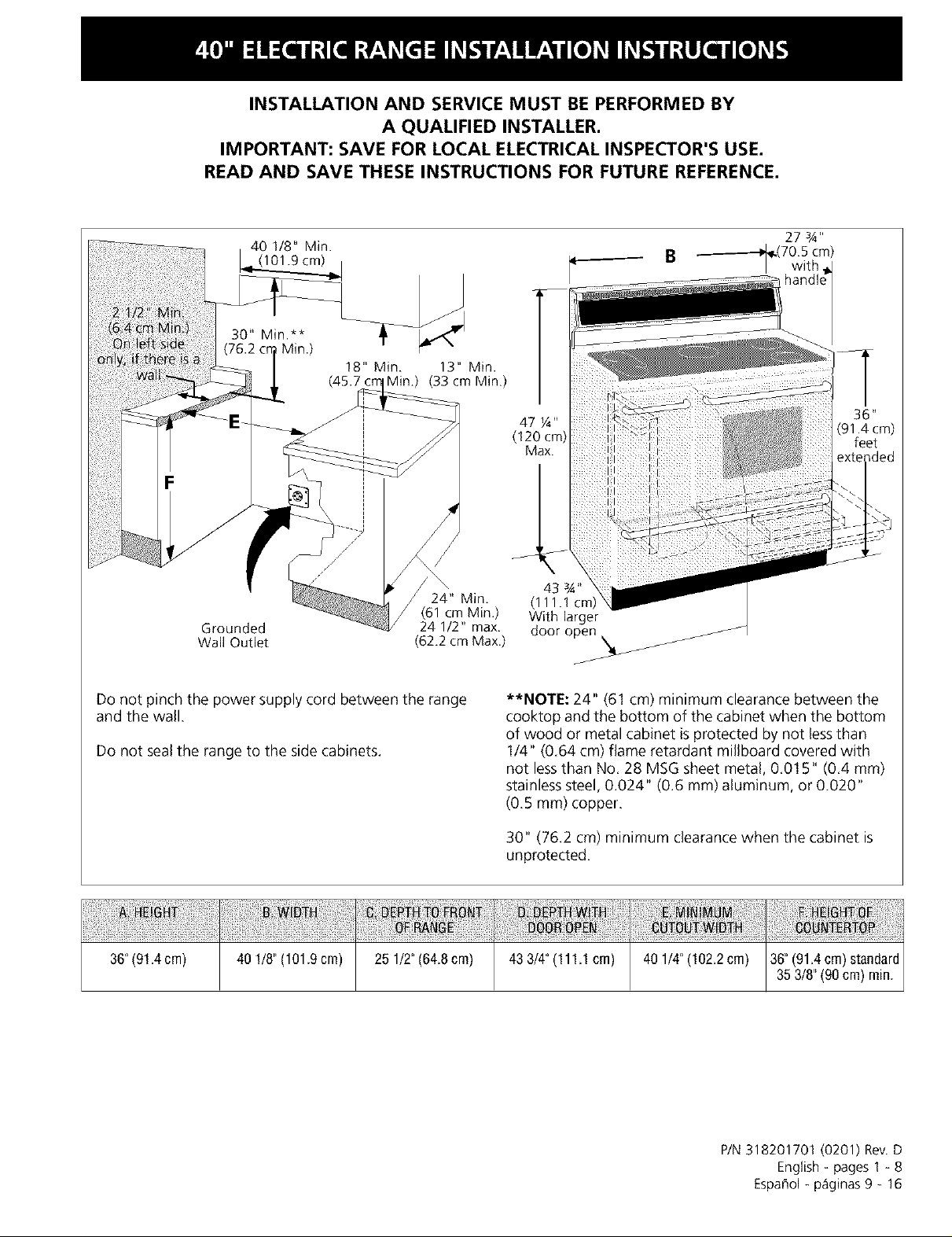
40 1/8" Min. _ 27 3A"
(101.9 cm) B _[_(70.5
24" Min. (1
Grounded
Wall Outlet
(61 cm Min.) With larger
24 1/2" max. door open /
(62.2 cmMax.) _/
Do not pinch the power supply cord between the range
and the wail.
Do not seal the range to the side cabinets.
cm)
/
47 ¼"
(120 cm)
Max.
36"
(91.4cm)
feet
**NOTE: 24" (61 cm) minimum clearance between the
cooktop and the bottom of the cabinet when the bottom
of wood or metal cabinet is protected by not lessthan
1/4" (0.64 cm) flame retardant millboard covered with
not lessthan No. 28 MSG sheet metal, 0.015" (0.4 mm)
stainless steel, 0.024" (0.6 ram) aluminum, or 0.020"
(0.5 mm) copper.
30" (76.2 cm) minimum clearance when the cabinet is
unprotected.
36"(91.4crn) 40 1/8"(101.9cm) 25 1/2"(64.8cm) 43 3/4"(111.1crn) 40 1/4"(102.2crn) 36"(91.4crn)standard
35 3/8"(90cm) rain.
P/N 318201701 (0201) Rev.D
English =pages 1 =8
Espafiol =p_iginas 9 = 16
Page 2
Important Notes to the Installer
1. Readall instructions contained in these installation
instructions before installing range.
2. Remove all packing material from the oven
compartments before connecting the electrical supply
to the range (see "Preparation ", page 6).
3. Install the 4 shipping bolts from range packaging as
range leveling legs (see "Levelingthe Range", page 7)
4. Two anti-tip brackets MUST beremoved from lower
back of range and MUST be installed (see "Anti-Tip
Bracket Installation ", page 8).
5. Observe all governing codes and ordinances.
6. Besure to leave these instructions with the consumer.
Important Note to the Consumer
Keep these instructions with your owner's guide for future
reference.
IMPORTANT SAFETY
INSTRUCTIONS
• Be sure your range is installed and grounded
properly by a qualified installer or service
technician.
• This range must be electrically grounded in
accordance with local codes or, in their absence,
with the National Electrical Code ANSI/NFPA No.
70--latest edition.
• The installation of appliances designed for
manufactured (mobile) home installation must conform
with Manufactured Home Construction and Safety
Standard, title 24CFR, part 3280 [Formerly the Federal
Standard for Mobile Home Construction and Safety,
title 24, HUD (part 280)] or when such standard is not
applicable, the Standard for Manufactured Home
Installation 1982 (Manufactured Home Sites,
Communities and Setups), ANSI Z225.1/NFPA 501A-
latest edition, or with local codes.
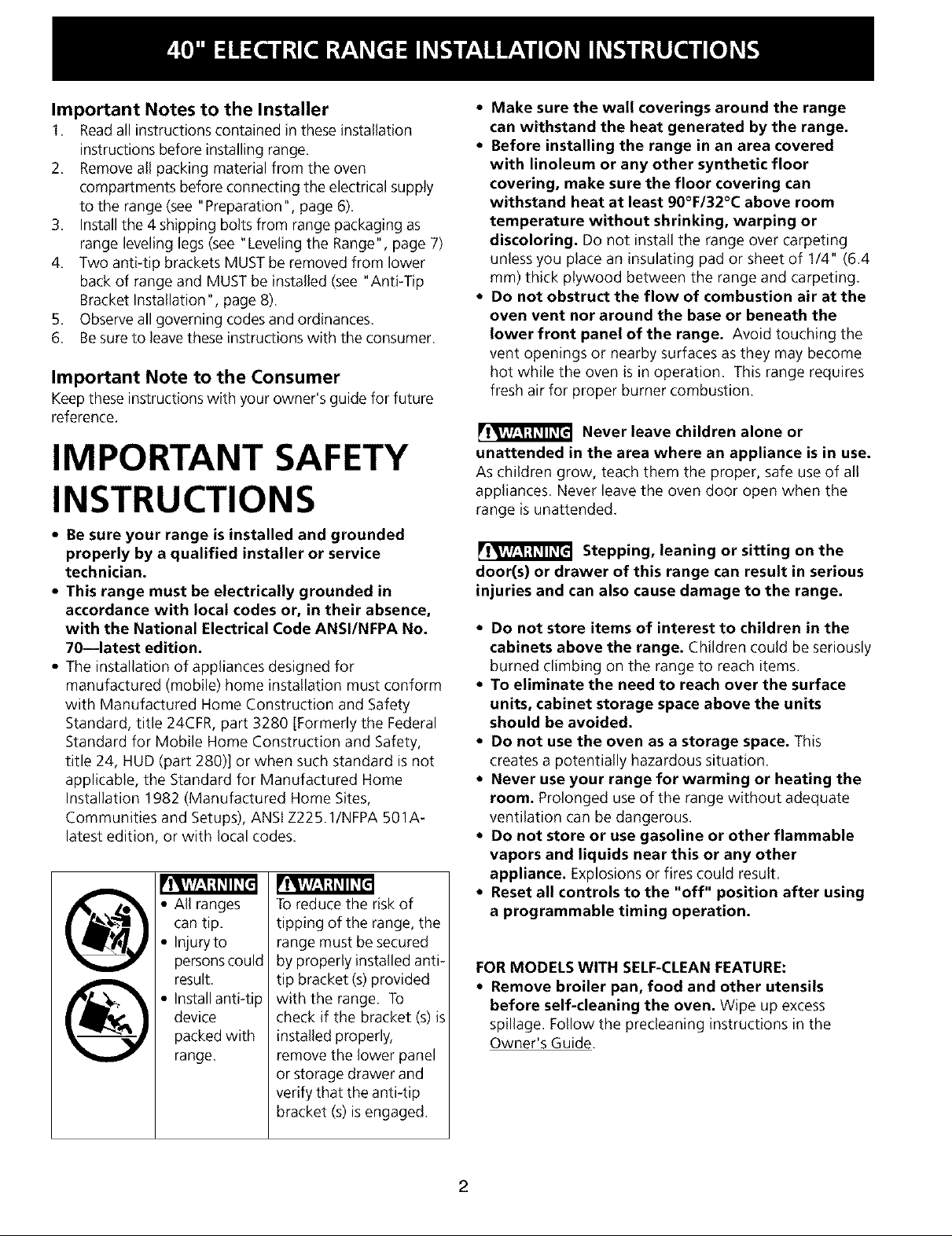
To reduce the risk of
tipping of the range, the
range must be secured
by properly installed anti-
tip bracket (s) provided
with the range. To
check if the bracket (s) is
installed properly,
remove the lower panel
or storage drawer and
verify that the anti-tip
bracket (s) is engaged.
®
®
All ranges
can tip.
Injuryto
personscould
result.
Installanti-tip
device
packed with
range.
• Make sure the wall coverings around the range
can withstand the heat generated by the range.
• Before installing the range in an area covered
with linoleum or any other synthetic floor
covering, make sure the floor covering can
withstand heat at least 90°F/32°C above room
temperature without shrinking, warping or
discoloring. Do not install the range over carpeting
unless you place an insulating pad or sheet of 1/4" (6.4
mm) thick plywood between the range and carpeting.
• Do not obstruct the flow of combustion air at the
oven vent nor around the base or beneath the
lower front panel ofthe range. Avoid touching the
vent openings or nearby surfaces as they may become
hot while the oven is in operation. This range requires
fresh air for proper burner combustion.
[l,W:_:l,_ll_[_l Never leave children alone or
unattended in the area where an appliance is in use.
As children grow, teach them the proper, safe use of all
appliances. Never leave the oven door open when the
range is unattended.
[I_W/'-_;I_II_[_I Stepping, leaning or sitting on the
door(s) or drawer of this range can result in serious
injuries and can also cause damage to the range.
• Do not store items of interest to children in the
cabinets above the range. Children could beseriously
burned climbing on the range to reach items.
• To eliminate the need to reach over the surface
units, cabinet storage space above the units
should be avoided.
• Do not use the oven as a storage space. This
creates a potentially hazardous situation.
• Never use your range for warming or heating the
room. Prolonged use of the range without adequate
ventilation can be dangerous.
• Do not store or use gasoline or other flammable
vapors and liquids near this or any other
appliance. Explosions or fires could result.
• Reset all controls to the "off" position after using
a programmable timing operation.
FOR MODELS WITH SELF-CLEANFEATURE:
• Remove broiler pan, food and other utensils
before self-cleaning the oven. Wipe up excess
spillage. Follow the predeaning instructions in the
Owner's Guide.
2
Page 3
Power Supply Cord Kit
The user is responsible for connecting the power supply
cord to the connection block located behind the back
panel access cover.
This appliance may be connected by means of
permanent "hard wiring" (flexible armored or
nonmetallic shielded copper cable), or by means of a
power supply cord kit. Useonly a power supply cord kit
rated at 125/250 volts minimum, 40 amperes minimum
and marked for use with ranges. See chart (below) for
cord kit connection opening size and rating information.
Cord must haveeither 3 or 4 conductors.
For mobile homes, new installations, recreational
vehicles, or areas where local codes do not permit
grounding through neutral, a 4 conductor power supply
cord kit rated at 125/250 volts minimum, 40 amperes
and marked for use with ranges should be used (see
Figure 4).
Terminals on end of wires must either be closed loop or
open-end spade lugs with upturned ends. Cord must
have strain relief clamp.
Risk of fire or electrical shock exists if
an incorrect size range cord kit is used, if the
Installation Instructions are not followed, or if the
strain relief bracket is discarded.
Range Connection Opening Size Chart
Refer to chart below for proper range connection opening size
and power supply cord kit ampere rating information See serial
plate on range for kilowatt rating data
Range Kilowatt Rating
See Serial Plate on Range)
120/240 Volts 120/208 Volts
0-16.5 kW 0-12.5 kW
166-225kW 126-185kW
Minimum Connection Opening
Cord kit
Ampere Direct
Rating Cord Kit Connection
40 Amp I-3/8 in I-1/8 in
50 Amp I-3/8 in I-3/8 in
Diameter (inches) of Range
NOTE: Range isshipped from factory with
1 1/8" dia. hole as shown in figure 3. If a larger hole
is required, punch out the knockout.
Electrical Connection to the Range
This appliance is manufactured with the neutral terminal
connected to the range.
While connecting range, do not
loosen the nuts which secure the terminal block to
the range. Electrical failure or loss of electrical
connection may occur.
Electrical Shock Hazard
Electrical ground is required on this appliance.
Do not connect to the electrical supply until
appliance is permanently grounded.
Disconnect power to the circuit breaker or fuse
box before making the electrical connection.
This appliance must be connected to a
grounded, metallic, permanent wiring system,
or a grounding connector should be connected
to the grounding terminal or wire lead on the
appliance.
Do not use the gas supply line for grounding
the appliance.
Failure to do any of the above could result in a
fire, personal injury or electrical shock.
Three Conductor Wire Connection to Range
(The 3-conductor cord or cable must be replaced with a
4-conductor cord or cable where grounding through the
neutral conductor is prohibited in new installations,
mobile homes, recreational vehicles or in other areas
where local codes do not permit neutral grounding)
If local codes permit connection of the frame grounding
conductor to the neutral wire of the copper power supply
cord (see Figure 3):
1. Remove the 3 screws at the lower end of the rear
wire cover, then bend the lower end of the rear wire
cover (access cover) upward to expose range
terminal connection block (see Figure 2).
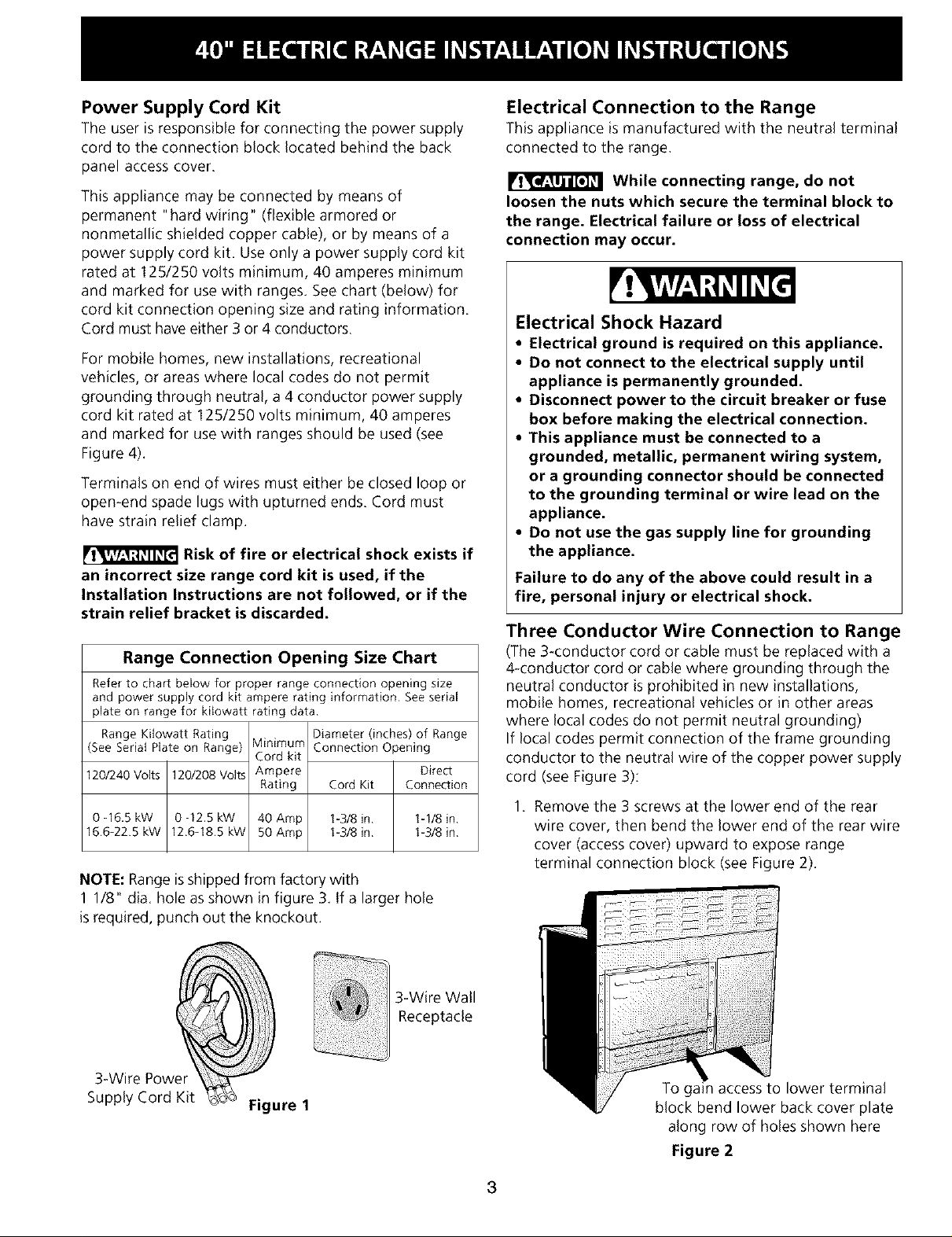
3-Wire Power
Supply Cord Kit
Figure 1
3-Wire Wall
Receptacle
To gain access to lower terminal
block bend lower back cover plate
along row of holes shown here
Figure 2
3
Page 4
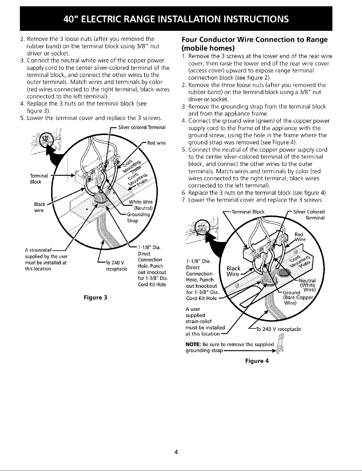
2. Remove the 3 loose nuts (after you removed the
rubber band) on the terminal block using 3/8" nut
driver or socket.
3. Connect the neutral white wire of the copper power
supply cord to the center silver-colored terminal of the
terminal block, and connect the other wires to the
outer terminals. Match wires and terminals by color
(red wires connected to the right terminal, black wires
connected to the left terminal).
4. Replace the 3 nuts on the terminal block (see
figure 3).
5. Lower the terminal cover and replace the 3 screws,
Terminal
Block
wire
Four Conductor Wire Connection to Range
(mobile homes)
1. Remove the 3 screws at the lower end of the rear wire
cover, then raise the lower end of the rear wire cover
(access cover) upward to expose range terminal
connection block (see figure 2).
2. Remove the three loose nuts (after you removed the
rubber band) on the terminal block using a 3/8" nut
driver or socket.
3. Remove the grounding strap from the terminal block
and from the appliance frame.
4. Connect the ground wire (green) of the copper power
supply cord to the frame of the appliance with the
ground screw, using the hole in the frame where the
ground strap was removed (see Figure 4).
5. Connect the neutral of the copper power supply cord
to the center silver-colored terminal of the terminal
block, and connect the other wires to the outer
terminals. Match wires and terminals by color (red
wires connected to the right terminal, black wires
connected to the left terminal).
6. Replace the 3 nuts on the terminal block (seefigure 4).
7. Lower the terminal cover and replace the 3 screws.
/8" Dia.
supplied by the user Connection
must be installed at
this location receptacle out knockout
Direct
Hole, Punch
for 1-3/8" Dia,
Cord Kit Hole
Figure 3
I-I/8" Dia.
Direct
Connection
Hole. Punch
out knockout
for I-3/8" Dia.
Cord Kit Hole
A user
supplied
strain-relief
must be installed
NOTE: Be sure to remove the supplie
at this location d
grounding strap
Figure 4
4
Page 5
Direct Electrical Connection to the Circuit
Breaker, Fuse Box or Junction Box
If the appliance isconnected directly to the circuit breaker,
fuse box or junction box, use flexible, armored or non
metallic sheathed copper cable (with grounding wire).
Supply a U.L listed strain-relief at each end of the cable.
At the appliance end, the cable goes through the Direct
Connection Hole (seefigure 4) on the Cord Mounting
Plate. Wire sizes(copper wire only) and connections must
conform to the rating of the appliance.
Where local codes permit connecting the appliance
grounding conductor to the neutral (white) wire
(see Figure 5).(The 3-conductor cord or cable must be
replaced with a 4-conductor cord or cable where
grounding through the neutral conductor is prohibited in
new installations, mobile homes, recreational vehicles or
in other areas where local codes do not permit neutral
grounding)
1. Disconnect the power supply.
2. In the circuit breaker, fuse box or junction box:
a) Connect the green (or bare copper) wire, the white
appliance cable wire, and the neutral (white) wire
together.
b) Connect the 2 black wires together.
c) Connect the 2 red wires together.
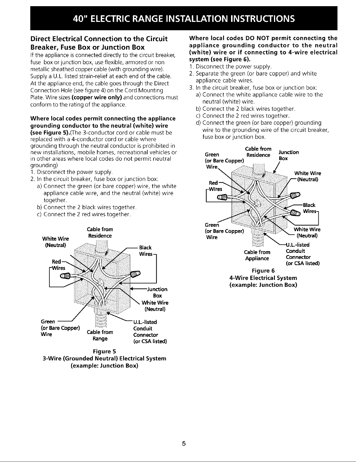
Where local codes DO NOT permit connecting the
appliance grounding conductor to the neutral
(white) wire or if connecting to 4-wire electrical
system (see Figure 6).
1. Disconnect the power supply.
2. Separate the green (or bare copper) and white
appliance cable wires.
3. In the circuit breaker, fuse box or junction box:
a) Connect the white appliance cable wire to the
neutral (white) wire.
b) Connect the 2 black wires together.
c) Connect the 2 red wires together.
d) Connect the green (or bare copper) grounding
wire to the grounding wire of the circuit breaker,
fuse box or junction box.
Cablefrom
Green Residence
(or BareCopper)
Junction
Box
Wire
Red
[wi
Cable from
White Wire
Residence
(Neutral)
Wires1
Box
(Neutral)
Green U.L.-listed
(or Bare Copper) Conduit
Wire Cable from Connector
Range (or CSA listed)
Figure 5
3-Wire (Grounded Neutral) Electrical System
(example: Junction Box)
(or Bare Copper)
Wire
Cable from Conduit
Appliance Connector
(or CSA listed)
Figure 6
4-Wire Electrical System
(example: Junction Box)
5
Page 6

Junction Box Location
Locate junction box as shown in Figure 7.
If a service cord is used, the wall receptacle should be
located in accordance with the dimensions below.
Center
Line of
Range
Inside Shaded Area
Figure 7
the cabinet. If back of range will not be flush with
the wall (the location of the outlet may not allow the
range to be positioned against the wall), draw a line on
the floor where the back edge of the range will be. Now
install anti-tip brackets (see "Anti-Tip Brackets
Installation", page 8).
If range will not be installed against a cabinet,
move range into final position. Mark on the floor along
both sides of the range. If back of range will not be
flush with the wall (the location of the outlet may not
allow the range to be positioned against the wall), draw
a line on the floor where the back edge of the range will
be. Now install anti-tip brackets (see "Anti-Tip Brackets
Installation", page 8).
Range Installation
When unpacking the range, do not
discard the 4 shipping bolts. These are to be replaced on
the unit for use as leveling legs and height adjustments.
Range Placement
TOeliminate the risk of burns or fire by
reaching over heated surface units, cabinet storage
space located above the range should be avoided. If
cabinet storage space isto be provided, the risk can be
reduced by installing a range hood that projects
horizontally a minimum of 5" (12.7 cm) beyond the
bottom of the cabinet.
0
Line of
O
Range
Center
, \
Follow instructions for
the type of installation you have
Figure 8
If range will be installed with a cabinet on both
sides, draw a center line on the floor between the
cabinets (see figure 8). If back of range will not be
flush with the wall (the location of the outlet may not
allow the range to be positioned against the wall), draw
a line on the floor where the back edge of the range will
be. Now install anti-tip brackets (see "Anti-Tip Bracket
Installation, page 8).
If range will be installed with a cabinet on one side
only, move the range into final position. Draw a line on
the floor along the side of the range that is not against
NOTE:
1. The back of the range may be installed directly
against the rear wall of the structure.
2. These ranges conform to Ui. requirements for "0"
spacing from the range to adjacent vertical walls
above the countertop level. However, to reduce
possible scorching of vertical walls and to minimize
potential fire hazards under abnormal surface unit
use conditions such as high heat or no pans, a
minimum of 2" (5.1 cm) spacing should be provided
on both sides of the cooktop.
Preparation
Excessive Weight Hazard
Use 2 or more people to move and install
range.
Failure to follow this instruction can result in
back or other injury.
1. Put on safety glasses and gloves. Remove oven racks
and parts package from inside the oven. Remove
shipping materials, tape and protective film from the
range.
2. Take 4 cardboard corners from the carton. Stack one
on top of another. Repeat with other 2 corners.
Place corners lengthwise on the floor in back of the
range to support range.
3. Firmly grasp the range and gently lay it on its back
on the cardboard corners.
4. Remove and save the 4 shipping bolts from the skid.
Discard skid.
6
Page 7

5. Install 4 shipping bolts as leveling legs.
6. Lay a large piece of cardboard in front of the range.
Carefully stand the range upright on cardboard.
7. Adjust the leveling legs to a point where the range
base does not touch the floor.
Leveling the Range
Level the range and set cooktop height before
installation in the cut-out opening (if applicable).
1. Install an oven rack in the center of the oven.
2. Place a level on the rack (see figure 9). Take 2
readings with the level placed diagonally in one
direction and then the other. Level the range, if
necessary, by adjusting the 4 leg levelers with a
wrench (see Figure 11).
3. Slide range into cut-out opening and double check
for levelness. If the range is not level, pull unit out
and readjust leveling legs, or make sure floor is
level.
2. Operation of Oven Elements
The oven is equipped with an electronic oven control. Each
of the functions hasbeen factory checked before shipping.
However, it issuggested that you verify the operation of
the electronic oven controls once more. Refer to the
Owner's Guide for operation. Follow the instructions for the
Clock, Timer, Bake, Broil, Convection (some models) and
Clean (some models) functions.
Bake-After setting the oven to 350°F (177°C) for baking,
the lower element in the oven should become red.
Broil-When the oven is set to BROIL,the upper element
in the oven should become red.
Clean (some models) When the oven is set for a self-
cleaning cycle, the upper element should become red
during the preheat portion of the cycle. After reaching
the self-cleaning temperature, the lower element will
become red.
Convection (some models)-When the oven is set to
CONV. BAKE/ROAST at 350°F (177°C), both elements
cycle on and off alternately and the convection fan will
turn. The convection fan will stop turning when the oven
door isopened during convection baking or roasting.
Figure 9
Check Operation
Refer to the Owner's Guide packaged with the range for
operating instructions and for care and cleaning of your
range.
Do not touch the elements. They may be
hot enough to cause burns.
Remove all packaging from the oven before testing.
1. Operation of Surface Elements
Turn on each of the four surface elements and check to
see that they heat. Check the surface element indicator
light(s), if equipped.
When All Hookups are Complete
Make sure all controls are left in the OFFposition.
Model and Serial Number Location
The serial plate is located on the oven front frame
behind the large oven door.
When ordering parts for or making inquiries about your
range, always be sure to include the model and serial
numbers and a lot number or letter from the serial plate
on your range.
Before You Call for Service
Read the Avoid Service Checklist and operating
instructions in your Owner's Guide. It may saveyou time
and expense. The list includes common occurrences that
are not the result of defective workmanship or materials
in this appliance.
Refer to the warranty and service information in your
Owner's Guide for our phone number and address.
Pleasecall or write if you have inquiries about your
range product and/or need to order parts.
7
Page 8

important Safety Warning
To reduce the risk of tipping of the range, the range
must be secured to the floor by properly installed anti-tip
brackets and screws packed with the range. Those parts
are located in a plastic bag in the oven. Failure to install
the anti-tip brackets will allow the range to tip over if
excessive weight is placed on an open door or if a child
climbs upon it. Serious injury might result from spilled
hot liquids or from the range itself.
Follow the instructions below to install the anti-tip
brackets.
If range is ever moved to a different location, the anti-tip
brackets must also be moved and installed with the
range. To check for proper installation, see step 5.
Tools Required:
5/16" (8 mm) Nutdriver or Flat Head Screwdriver
Adjustable Wrench
Electric Drill
3/16" (4.8 mm) Diameter Drill Bit
3/16" (4.8 mm) Diameter Masonry Drill Bit (if installing
in concrete)
Anti-Tip Brackets Installation Instructions
Brackets attach to the floor at the back of the range to
hold both rear leg levelers. When fastening to the floor,
be sure that screws do not penetrate electrical wiring or
plumbing. The screws provided will work in either wood
or concrete.
1. Unfold paper template and place it flat on the floor
with the back and side edges positioned exactly
where the back and sides of range will be located
when installed. (Use the diagram in figure 10 to
locate brackets if template is not available.)
2. Mark on the floor the location of the 4 mounting
holes (2 holes per bracket) shown on the template.
For easier installation, 3/1 6" (4.8 mm) diameter pilot
holes 1/2"(1.3 cm) deep can be drilled into the floor.
3. Remove template and place brackets on floor with
turned up flanges to the outside (see figure 10). Line
up holes in brackets with marks on floor and attach
with 4 screws provided (2 screws per bracket).
Brackets must be secured to solid floor. If attaching
to concrete floor, first drill 3/16" (4.8 mm) dia. pilot
holes using a masonry drill bit.
4. Level range if necessary, by adjusting 4 leg levelers
with wrench. (See Figure 11). A minimum clearance
of 1/8" (3.2 mm) is required between the bottom of
the range and the rear leg levelers to allow room for
the anti-tip brackets.
5. Slide range into place making sure rear legs are
trapped by ends of brackets. Range may need to be
shifted slightly to one side as it is being pushed back
to allow rear legs to align with brackets.
6. After installation, verify that the anti-tip bracket is
engaged. Open and remove drawer and check to
make sure the anti-tip bracket is engaged.
Anti-Tip
Bracket
Back
Anti-Tip
Bracket
(1.9 cm)
Figure 10 Figure 11
8
Page 9

LA INSTALACION Y EL SERVICIO DEBEN SER EFECTUADOS POR
UN INSTALADOR CALIFICADO.
IMPORTANTE: GUARDE ESTAS INSTRUCCIONES PARA USO DEL
INSPECTOR LOCAL DE ELECTRICIDAD.
LEA Y GUARDE ESTAS INSTRUCCIONES PARA REFERENCIA FUTURA.
40 1/8" Min. 27 3A"
(101.9cm) B -- "'Con la manija
J' Min.
(45.7 cm Min.) (33 cm Min.)
(70.5 cm)
F
Toma corrient_
pared puesto a tierra
No pellizque el cord6n el_ctrico entre la estufa y la pared.
No selle la estufa a los armarios de lado.
47 ¼"
(120 cm)
m_ix.
36 "
(91.4cm)
con las
patas
extendidas
43 N"
Con lapuerta
grande abierta
**NOTA: Un espacio minimo de 24" (61 cm) entre la
superficie de la estufa y el fondo del armario cuando el
fondo del armario de madera o metal est_ protegido por
no menos de 1/4" (0.64 cm) de madera resistente al
fuego cubierta pot una I_imina met_lica de MSG, n0mero
28, 0.015" (0.4 mm) de acero inoxidable, 0.024" (0.6
mm) de aluminio, 6 0.02" (0.5 mm) de cobre.
Un espacio minimo de 30" (76.2 cm) cuando el armario
no est,1protegido.
36"(91,4cm) 40 1/8"(101.9cm) 25 1/2"(64,8cm) 43 3/4"(111.1cm) 40 1/4"(102.2cm) 36"(91.4¢m) norrnal
35 3/8"(90cm) rain.
P/N 318201701 (0201) Rev.D
English * pages 1 * 8
Espa_ol _ p_iginas 9 _ 16
Page 10

Notas importantes para el Instalador
1. Lea todas las instrucciones contenidas en este manual
antes de instalar la estufa.
2. Saque todo el material usado en el embalaje del
compartimiento del homo antes de conectar el
suministro el_ctrico a la estufa.
3. Guarde los 4 pemos del empaque de la estufa para
usarlos como patas niveladoras.
4. Dos soportes antivuelco DEBEN quitarse de la parte de
inferior trasera de la estufa y DEBEN ser instalados.
Para detalles, vea instrucciones en la p_iginas 16.
5. Observe todos los cOdigos y reglamentos pertinentes.
6. Deje estas instrucciones con el comprador.
Nota Importante para el Consumidor
Conserve estas instrucciones y el Manual del Usuario para
referencia futura.
IMPORTANTES
• Asegurese de que el material que recubre las
paredes alrededor de la estufa, pueda resistir el
calor generado por la estufa.
• Antes de instalar la estufa en un area cuyo piso
este recubierto con IinOleo u otro tipo de piso
sint_tico, asegt_rese de que _stos puedan resistir
una temperatura de por Io menos 90°F sobre la
temperatura ambiental sin provocar
encogimiento, deformaciOn o decoloraciOn. No
instale la estufa sobre una alfombra al menos que
coloque una plancha de material aislante de pot lo
menos 1/4 pulgada, entre la estufa y la alfombra.
• No obstruya el flujo del aire de combustibn en la
ventilacibn del homo ni tampoco alrededor de la
base o debajo del panel inferior delantero de la
estufa. Evitetocarlasaberturaso_reascercanasde
la ventilaciOn, ya que pueden estar muy calientes
duranteelfuncionamientodel homo. La estufa
requiere aire fresco para la combustion apropiada de
los quemadores.
INSTRUCCIONES DE
SEGURIDAD
• Asegt_rese de que la estufa sea instalada y
conectada a tierra en forma apropiada pot un
instalador calificado o pot un t_cnico.
• Esta estufa debe ser eldctricamente puesta a
tierra de acuerdo con los cOdigos locales, o en su
ausencia, con el Cbdigo Eldctrico Nacional ANSI/
NFPA No. 70, (_ltima ediciOn.
• La instalaciOn de aparatos disehados para instalaciOn
en casas prefabricadas (mOviles) debe conformar con
el Manufactured Home Construction and Safety
Standard, titulo 24CFR, parte 3280 [Anteriormente el
Federal Standard for Mobil Home Construction and
Safety, titulo 24, HUD (parte 280)] o cuando tal
estandard no se apNca, el Standard for Manufactured
Home installation 1982 (Manufactured Home sites,
Communities and Setups), ANSI Z225.1/NFPA 501A-
ediciOn m_is reciente, o con los cOdigos locales.
•Todas las
estufas pueden
volcarse.
• Esto podria
resultar en
lesiones
personales.
• Instale el
dispositivo
antivuelcos que
se ha
empacado
junto con esta
estufa.
Pararedudr el riesgo de
que sevuelque la estufa,
hay que asegurarla
adecuadamente
coloc_indole los soportes
antivuelco que se
propordonan. Para
comprobar si estos est_in
instalados y apretados en
su lugar como sedebe. ase
el borde trasero superior de
la estufa y cuidadosamente
inclfnela hada adelante
para asegurar que laestufa
seancle.
desatendidos en un area donde un artefacto est&
Nunca deje ni_os solos o
siendo usado. A medida que los ni_os crecen,
enseheles el uso apropiado y de seguridad para todos los
artefactos. Nunca deje la puerta del homo abierta
cuando la estufa est.1 desatendida.
r!_ No se pare, apoye o siente en las
puertas o cajones de esta estufa pues puede
resultar en serias lesiones y puede tambien causar
daho a la estufa.
• No almacene articulos que puedan interesar a los
nihos en los gabinetes sobre la estufa, Los nihos
pueden quemarse seriamente tratando de trepar a la
estufa para alcanzar estos articulos.
• Los gabinetes de almacenamiento sobre la estufa
deben ser evitados, para eliminar la necesidad de
tener que pasar sobre los elementos superiores de
la estufa para llegar a ellos.
• No use el homo como espacio de almacenaje. Esto
crear_ una situaciOn potencialmente peligrosa.
• Nunca use la estufa para calentar el cuarto. El uso
prolongado de la estufa sin la adecuada ventilaciOn
puede resultar peligroso.
• No almacene ni utilice gasolina u otros vapores y
liquidos inflamables en la proximidad de dste o
de cualquier otro artefacto electrico. Puede
provocar incendio o explosiOn.
• Ajuste todos los controles a la posicibn "OFF"
(apagada) despues de haber hecho una operacibn
con tiempo programado.
PARA MODELOS AUTOLIMPIANTES:
• Saque la asadera, alimentos o cualquier otto
utensilio antes de usar el ciclo de autolimpieza
delhomo. Limpietodoexcesodederramede
alimentos. Sigalasinstruccionesde prelimpiadoenel
Manual del Usuario.
10
Page 11

Juego de Cordbn El_ctrico
El consumidor tiene la responsabilidad de conectar el
cordon el_ctrico al bloque de conexiOn ubicado detr4s de
la cubierta de acceso del panel trasero,
de
Este artefacto puede ser conectado mediante "cableado
rfgido" permanente (un cable fexible escudido o un
cable de cobre escudido no met41ico) o un "juego de
cordon electrico'L Se usar4 solamente un juego de
cordon electrico para 125/250 voltios minimo, 40
amperios minimo y marcado para uso con estufas. El
juego de cordon electrico debe tener 3 o 4 conductores,
Para las casas sobre ruedas, las nuevas instalaciones, en
los vehiculos de recreaciOn o en las 4reas donde los
cOdigos locales no permiten la conexiOn del conductor a
tierra al neutro, un ensamblaje de suministro el_ctrico de
4 conductores para estufas, clasificado a 125/250 voltios
minimo, 40 amperios minimo, debe de ser utilizado (vea
Figura 4).
Los terminales en las puntas de los alambres deben ser
de circuito cerrado o de orejeta de pala punta abierta y
con las puntas vueltas hacia arriba, El cordon debe tener
un andaje del cable,
Puede ocurrir riesgo de incendio o
choque el_ctrico si se usa un juego de cord6n de
estufa de tamaffo incorrecto, si las instrucciones de
instalaci6n no son seguidas o si no se usa el anclaje
del cable.
Tabla de tamafio de abertura de conexi6n de cocina
Referirse a la tabla de arriba para et tama_o de abertura de
connexi6n de cocina adecuada, y la informaciOn sobre el regimen
de amperios del ensamblaje de cord6n de suministro el_ctdco
Vea la plata de serie de la
codna para informaciOn
sobre el regimen de
k[Iovatio
120/240 Volts I20/208 Volts
0-185 Kw 0-125 Kw 40 Amp
I86-22.5Kw 12.6-185Kw 50 Amp
Minimo
regimen de
amperios
de
ensamblaje
del cordon
Diametro (pulgadas) de
abierta de conexi6n de
cocina
DimensiOn ConexiOn
agujero directo
Connexi6n
13/8 putg 1 1/8pulg
13/8 pulg 1 3/8 pulg
NOTA: Laestufa viene de f_ibrica preparada para funcionar
con un hueco de 1 1/8" de diametro come se muestra en la
figura 3. En caso de necesitarse un hueco m4sgrande retire
la cubierta.
lrl1-.i;l::_:]u_..l[,],,i AI realizar la conexiOn de la estufa, no
desaprete lastuercas que aseguran el alambraje de la
estufa al bloque terminal instalado en la flibrica. Se puede
ocurrir corte de energia o perdida de conexi6n electrica.
Juego de CordOr_
de Suministro
El_ctrico de 3
Alambres
Figura 1
Conexi6n El_ctrica de la Estufa
Este aparato se fabrica con el terminal neutro conectado
al marco.
Riesgo de Choque El_ctrico
• Una puesta a tierra est_ requerido en este
aparato.
• No Io conecte a la corriente el_ctrica hasta que
el aparato haya sido puesto a tierra
permanentemente.
• Desconecte la corriente electrica a la caja de
empalmes antes de hacer la conexi6n electrica.
• Este aparato debe estar conectado con un
sistema de alambres puesto en tierra, metalico
y permanente o un conector de puesta a tierra
debe conectarse al terminal de puesta a tierra
o el alambre conductor en el aparato.
La falta de hacer cualquier de las cosas arriba
podria resultar en un incendio, choque el_ctrico
o lesiones personales.
Conexi6n de tres alambres de conducci6n a
la estufa
(Un cord6n flexible o cable de 3 conductores debe de ser
reemplazado con un cord6n flexible o cable de 4 conducto-
res donde la conexi6n del conductor a tierra al neutro esta
prohibida en las nuevas instalaciones, las casas sobre
ruedas, los vehfculos de recreaci6n o otras 4reas donde los
c6digos locales no
permiten la
conexi6n a tierra al
neutro.)
Si los c6digos
locales permiten
la conexi6n del
conductor de
tierra del marco
con el alambre
neutro del cord6n
electrico de cobre
(vea Figura 3):
Figura 2 de agujeros que se yen aqu[
Para obtener acceso al
tablero inferior de bornes,
doble hacia atr_s la placa de
la cubierta trasera por la ilia
11
Page 12

1. Quite los tres tornillos en la parte m_s baja del panel
trasero, luego levante la parte m_s baja del panel
trasero (la cubierta de acceso) exponiendo el bloque
de conexiones de los terminales de la estufa (vea
Figura 2).
2. Quinte las tres tuercas desatadas (despu_s de
remover la cinta de goma) sobre el bloque terminal
usando un destornillador o una llave de casquillo de
3/8".
3. Conecte el cable neutro del cordon electrico de cobre
al terminal de color de plata en el centro del bloque,
y conecte los otros cabels a los terminales laterales.
Empareje los cables y los terminales segOn el color
(cables rojos conectados con el terminal derecho,
cables negros conectados con el terminal izquierdo).
4. Baje la cubierta del terminal y reinstale los tres (3)
tornillos.
5. Baje la cubierta del terminal y reponga los 3 tornillos.
Je terminal
)lata
Conexi6n de 4 alambres de conducci6n a la
estufa (casas m6viles)
1. Quite los tres tornillos en la parte m_s baja del panel
trasero, luego levante la parte m2s baja del panel
trasero (la cubierta de acceso) exponiendo el bloque
de conexiones de los terminales de la estufa (vea
figura 2).
2. Retire las 3 tuercas (despu_s de haber removido la
banda de goma) sobre el bloque terminal usando un
manguito o destornillador de casquillo de 3/8"
pulgadas.
3. Quite la banda de puesta a tierra del bloque de los
terminalesydelmarcodelartefacto. Retengael
tornillo de puesta a tierra.
4. Conecte el alambre de puesta a tierra (verde) del
cordon electrico de cobre al marco del artefacto con
el tornillo de puesta a tierra, usando el agujero en el
marco donde se quit0 el tornillo de puesta a tierra
(yea figura 4).
5. Conecte el alambre neutro (blanco) del cordon
electrico de cobre al terminal de color de plata en el
centro del bloque y conecte los otros alambres al los
terminales laterales. Conecte los alambres y
terminales emparejando los colores (los alambres rojos
conectsdos al terminal derecho, los alambres negros
conectados al terminal izquierdo).
6.Reponga las 3 tuercas sobre el bloque terminal (vea
figura 4).
7. Baje la cubierta de acceso y vuelva a porter los 3
tornillos.
Una arazadera
de releva
provista debe de
estar instalada a
est_ ubicaci6n
Hacia el 240 V
recept_culo
Figura 3
I/8" Dia.
Agujero de la
conexi6n directa,
Retira la arandela
pre-cortada para
I-3/8" Dia. Agujero
rminal
1-1/8" Dia.
Agujero de la
conexiOn
directa.Retira
la arandela
pre-cortada
para 1-3/8" Dia
Agujero
Una arazadera
de releva provista
debe de estar
instalada a est_ Hacia el 240 V
ubicaciOn recept_culo
NOTA: Asegurese de quitar la banda de puesta a tierra _)_/
provista.
Figura 4
12
Page 13

Conexibn el_ctrica directa al cortacircuito, a
la caja de fusibles o la caja de empalmes
Si el aparato esta conectado directamente al cortacircuito,
a la caja de fusibles o a Ia caja de empalmes, use un cable
blindado flexible o no metalico recubierto de cobre (con
alambre a tierra). Provee una abrazadera releva de anclaje
homologo UL a cada extremidad del cable. A la
extremidad del electrodomestico, el cable pase a traves del
agujero de la conexi6n directa (yea figura 4) en el cable de
la placa de montaje. El tama_o de los alambres (alambre
de cobre solamente) y las conexiones deben estar
conforme al regimen del electrodom_stico.
Donde los cbdigos locales permitan conectar el
conductor de puesta a tierra del electrodomestico al
neutral (blanco) (vea figura 5):
(Un cord6n flexible o cable de 3 conductores debe de ser
reemplazado con un cord6n flexible o cable de 4 conducto-
res donde la conexi6n del conductor a tierra al neutro esta
prohibida en las nuevas instalaciones, las casas sobre
ruedas, los vehfculos de recreaci6n o otras areas donde los
c6digos locales no permiten la conexi6n a tierra al neutro.)
1. Desconecte el suministro electrico.
2. En el cortacircuito, la caja de fusibles o la caja de
empalmes
a) Conecte el alambre verde (o cobre desnudo), el
alambre blanco del cable del electrodomestico y el
alambre neutral (blanco) juntos.
b) Conecte los dos alambres negros juntos.
c) Conecte los dos alambres rojos juntos.
Cablede lafuente
Alambre
Blanco
(Neutro)
Alambres--
de alimentaci6n
Donde los cbdigos locales NO permitan conectar el
conductor de puesta a tierra del el_ctrodomestico al
neutral (blanco), o si estb conectado con un sistema a
4 alambres (vea figura 6):
1. Desconecte el suministro electrico
2. Separe el alambre verde (o cobre desnudo) y el
alambre blanco del electrodom_stico.
3. En el cortacircuito, la caja de fusibles o la caja de
empalmes.
a. Conecte el alambre blanco del cable del
el_ctrodom_stico al alambre neutral (blanco).
b. Conecte los 2 alambres negros juntos.
c. Conecte los 2 alambres rojos juntos.
d. Conecte el alambre verde (o de cobre desnudo) de
la puesta a tierra del alambre al alambre de
puesta a tierra del cortacircuito, de la caja de
fusibles o de la caja de empalmes.
Alambre Cable de la fuente Caja de
desnudo o de alimentaci6n empalmes
verde Alambrelanco
rAlc;omsb eutro)
Alambres
negros
Alambres
desnudos o Alambre
verdes Blanco
estufa uni6n listado-UL
(o listado-CSA)
Figura 6 - Sistema el_ctrico de 4 alambres
(ejemplo caja de empalme)
Blanco
Alambres
desnudos
o verdes
Cable de la (listado-CSA)
estufa
(Neutro)
uni6n listado-UL
Figura 5 - Sistema electrico (ejemplo: caja de
empalmes) de 3 alambres (a tierra neutral)
13
Page 14

Situacibn de caja de unibn
Localice
Figura 7.
Si se usa un cordon de servicio, el recept_culo de pared
debe estar localizado segOn las medidas que se indican
abajo.
la
caja de empalmes como se ve en
Center
Line af
Rang DELA ESTUFA
SOMBREADA ESTUFA
Figura 7
la
Construccibn de los Armarios
Si la estufa se va a instalar con un armario a s61o un
lado, mueva la estufa a su posici0n final. Marque el piso
pot el lado de la estufa que no estara contra el armario.
Si la parte trasera de la estufa no estara a ras con la
pared (la ubicaci0n del tomacorriente puede que no
permita que la estufa se pegue a ras con la pared),
marque el piso donde el horde trasero de la estufa estar_.
Ponga el patron en el piso y alinie el lado del patron con
la linea marcada en el piso. Alinie la parte trasera del
patron con la pared trasera o la linea marcada para la
parte de atr_s de la estufa.
Si la estufa no sera instalada junta contra un armario,
mueva la estufa a su posiciOn final. Marque el piso por los
dos lados de la estufa. Si la parte trasera de la estufa
no estara a ras con la pared (la ubicaci0n del
tomacorriente puede que no permita que la estufa se
pegue a ras con la pared), marque en el piso donde el
horde trasero de la estufa estar_. Ponga el patron en el
piso y alinie los lados del patron con las lineas marcadas
en el piso. Alinie la parte trasera del patron con la pared
trasera o la linea marcada para la parte trasera de la
estufa (yea instalaciOn del Soportes Antivuelco p_gina 8).
Para eliminar el riesgo de quemaduras
e incendios al tocar superficies sobrecalentadas, se debe
evitar colocar espacio para armarios de almacenamiento
sobre las estufas con elementos al descubierto. Si se
instalan armarios sobre la estufa, se pueden reducir tales
riesgos instlando una campana purificadora que se
proyecta horizontalemente un minimo de 5" (12.7 cm)
mas afuera de la parte inferior de los armarios.
i
Line of
O
Siga las instrucciones para el tipo de
instalaciOn que usted tenga
Si la estufa se va a instalar con un armario a ambos
lados, marque el centro de la abertura del armario en el
piso. Si la parte trasera de la estufa no estara a ras
con la pared (la ubicaci0n del tomacorriente puede que
no permita que la estufa se pegue a ras con la pared),
marque el piso donde estar_i el border trasero de la estufa.
Ponga el patron en el piso, alineando la linea del centro
del patron con la marca en el centro de la abertura del
armario. Ponga el borde trasero del patron a ras contra la
pared trasera o la linea marcada para la parte de atr_is de
la estufa.
Range
I
Center
Figura 8
Instalacibn de la estufa
Mientras se desembala la estufa, ne
deseche los cuatro (4) pernos de embabalaje.
Reemplacelos como patas niveladoras y para ajustar la
altura de la unidad.
NOTA:
1. La parte trasera de la estufa puede ser directamente
instalada a ras con la pared trasera de la estructura.
2. Estas estufas se conforman a los requerimientos U.L
para espaciamiento "0" desde la estufa hasta las
paredes verticales adyacentes arriba del nivel del
tablero. No obstante, para reducir la posibilidad de
quemar las paredes verticales y para disminuir el
posible peligro de incendio bajo condiciones anormales
de uso de la tapa con hornillas como alto calor o la
ausencia de cazuelas, se debe dejar un espacio de un
minimo de 2" (5.1 cm) en ambos lados de la tapa.
Preparacibn
Peligro de Peso Excesivo
• Use 2 personas o m&s para mover e instalar la
estufa.
• Si no cumple con esta instruccibn, puede resultar
en da_o a la espalda u otra lesibn.
1. POngaseguantes y anteojos de seguridad. Quite las
parrillas del homo y paquete de piezas de adentro del
homo. Quite materiales de empaque, cinta y pelicula
protectiva de la estufa.
14
Page 15

2. Tome las 4 esquinas de cart6n de la caja de empaque.
Col6quelas una encima de otra. Repita esta operaci6n
con las otras 2 esquinas. Coloque las esquinas
Iongitudinalmente en el piso detr_s de la estufa, para
apoyarla.
3. Sujete firmemente la estufa y suavamente recu_stela
en su respaldo, en las esquinas de cart6n.
4. Quite y guarde los 4 pernos de empaque de la
corredera. Descarte la corredera.
5. Instale los 4 pernos de transporte como patas de
nivelaci6n.
6. Ponge el cart6n delante de la estufa. Cuidadosamente
pare la estufa en el cart6n.
7. Ajuste la patas de nivelaci6n al punto en que la base
de la estufa no toque el piso.
2. Funcionamiento de los Elementos del Horno
El horno est_ equipado con un control electr6nico. Cada
funci6n ha sido probada en la f_brica antes del transporte.
Sin embargo, sugerimos que Ud. verifique el
funcionamiento de los controles del homo una vez m_s.
Vease el Manual del Usuario para la operaci6n. Siga las
instrucciones par el Reloj, Minutero, Cocer, Asar,
Covecci6n (algunos modelos) y las funciones de limpieza
(algunos modelos).
Cocer/Bake-Despu_s de poner el homo a 350°F (177°C)
para cocer, el element inferior debe ponerse rojo
Asar/BroiI-Cuando est_ puesto para BROIL, el elemento
superior se debe poner rojo.
Nivelacibn de la estufa
Nivele la estufa y ajuste la altura de la estufa antes
de instalarla en la abertura.
1. Coloque una parrilla del homo en el centro del homo.
2. Ponga un nivel sobre la parrilla (yea figura 9). Tome
dos lecturas con el nivel puesto diagonalmente en una
direcci6n y despues en la otra. Nivele la estufa, si es
necesario, ajustando las 4 patas niveladoras con una
llave de tuercas (Figura 10).
3. Deslice la estufa en la abertura y verifique la nivelaci6n
otra vez. Si la estufa no es nivelada, tire la unidad
hacia afuera y reajuste las patas niveladoras, o verifique
que el piso sea niveIado.
Figura 9
Comprobaci6n del Funcionamiento
Consulte el Manual del Usuario incluido con la estufa
para instrucciones de operaci6n y instrucciones para el
cuidado y limpieza de su estufa.
III'll;i;]:_:_l[_[°]_l No toque los elemento. Pueden estar
bastante calientes para causar quemaduras.
Quite todo el embalaje de la unidad antes de
comprobarla.
1. Operaci6n de los elementos de superficie
Encienda cada uno de los cuatro elementos de superficie y
controle que se calienten. Vefifique el funcionamiento de
las lutes indicadoras de los elementos de supefficie, si
equipadas.
Limpieza/Clean (algunos modelos)-Cuando el homo
est_ puesto para un ciclo de auto-limpieza, el element
superior se pondr_ rojo durante el periodo de
precalentamiento del ciclo. Despu_s de alcanzar la
temperatura de auto-limpieza, el elemento inferior se
pondr_ rojo.
Convecci6nlConvection (algunos modelos)-Cuando
el homo se pone a CONV. BAKE/ROAST a 350°F
(177°C), los dos elementos se enciendan y se apagan
alternando en un ciclo y el ventilador se pone en
marcha. EIventiladordeconvecci6nse parar_ cuando
se abre la puerta del homo durante el cocido o el asado
por convecciOn.
Despu_s de Terminar la Instalaci6n
Aseg0rese de que todos los controles est_n en la posici6n
OFF (apagada).
Ubicaci6n del N_mero de Modelo y de Serie
La placa con el n0mero de serie est_ ubicada en el
marco delantero del homo detr_s de la puerta del homo
grande.
Cuando haga pedidos de repuestos o solicite informaci6n
con respecto a su estufa, este siempre seguro de incluir
el n0mero de modelo y de serie y el n0mero o letra del
Iote de la placa de serie de su estufa.
Antes de Llamar al Servicio
Lea la secci6n Lista de control de averias en su Manual
delUsuario. Estole podr_ahorrar tiempoygastos. Esta
lista incluye ocurrencias comunes que no son el
resultado de defectos de materiales o fabricaci6n de
este artefacto.
Lea la garantia y la informaci6n sobre el servicio en su
Manual del Usuario para obtener el n0mero de tel_fono
gratuito y la direcci6n del servicio. Pot favor Ilame o
escriba si tiene preguntas acerca de su estufa o necesita
repuestos.
15
Page 16

Importante Advertencia de Seguridad
Para reducir el riesgo de que la estufa se vuelque, es
necesario asegurarla al piso instalando los soportes
antivuelco y los tornillos suministrados con la estufa. Las
piezas se encuentran en un saco de plastico en el horno.
Si no se instalan los soportes antivuelco, la estufa se
puede volcar si se coloca exceso de peso en una puerta
abiertaosiun nihosesubeaella. Sepuedenocasionar
lesiones graves causadas por los Ifquidos calientes
derramados o por la estufa misma.
Siga las instrucciones que mas abajo se indican para
instalar los soportes antivuelco.
Si la estufa es movida a otro lugar, los soportes
antivuelco deben tambien set movidos e instalados en la
estufa. Para controlar la instalaci6n apropiada, vea el
paso n0mero 5.
Herramientas Necesarias:
Llave de tuerca de 5/16" (8 mm) o destornillador para
tornillos de cabeza plana
Llave inglesa
Taladro electrico
Broca de 3/16" (4.8 mm) de di_imetro
Broca para taladro de mamposteria de 3/16" (4.8 mm)
de di_i. (si se est,1instalando en concreto)
Instrucciones de Instalacibn del Soporte
Antivuelco
Los soportes se fijan al suelo en la parte trasera de la
estufa para sujetar ambos niveladores de las patas
traseras. Cuando los este instalando al piso, aseg0rese
de que los tornillos no penetren el alambrado electrico o
plomerfa. Los tornillos provistos pueden utilizarse en
madera o concreto.
1. Desdoble la plantilla de papel y colOquela plana en
el piso con los bordes laterales y el trasero colocados
exactamente donde la parte trasera y los lados de la
estufa ser_n colocados cuando sea instalada. (Use el
diagrama siguiente para ubicar los soportes si no se
dispone de la plantilla).
2. Marque en el piso la ubicaci6n de los 4 agujeros de
montaje como se muestra en la plantilla. Para
facilitar la instalaci6n, se pueden taladrar agujeros
piloto de 3/16" (4.8 mm) de diam. y 1/2" (1.3 cm)
de profundidad en el piso.
3. Saque la plantilla y coloque los soportes en el piso
con la brida hacia arriba dirigida hacia el frente.
Alinee los agujeros en los soportes con las marcas en
el piso y sujete con los 4 tornillos provistos. Los
soportes deben estar asegurados al piso firme. Si se
va a instalar en piso de concreto, primero debe
taladrar agujeros gufa de 3/16" (4.8 mm) de
di_metro usando una broca para taladro de
mamposteria.
4. Nivele la estufa si es necesario ajustando las cuatro
patas niveladoras con una llave (Ver la Figura 11
abajo). Se requiere un espacio libre minimo de 1/8"
(3.2 mm) entre la parte inferior de la estufa y los
niveladores de las patas traseras para dejar espacio
para los soportes antivuelco.
5. Deslice la estufa a su lugar asegur_ndose de que las
patas traseras esten sujetas pot los extremos de los
soportes. Laestufa puede necesitar set movida
ligeramente a un lado cuando est_ siendo empujada
hacia atr_is para permitir que las patas se alineen con
los soportes. Usted tambien puede asir el borde
trasero de la cima de la estufa y cuidadosamente
intentar voltearIa para asegurarse de que la estufa
sea adecuadamente anclada.
Deslice
Hacia atras
\
Figura 11
16
 Loading...