

Page 1
IMPORTANT:SAVEFORLOCALELECTRICAL INSPECTOR'S USE,
READ AND SAVE THESE INSTRUCTIONS FOR FUTURE REFERENCE.
OBSERVE ALL GOVERNING CODES AND ORDINANCES.
if the information in this manuaJ is not foJJowed exactJy, a fire or expJosion may resuJt
causing property damage, personaJ iniury or death.
FOR YOUR SAFETY:
-- Do not store or use gasoline or other flammabJe vapors and Jiquids in the vicinity of this or
any other appliance.
-- WHAT TO DO IF YOU SMELL GAS:
Do not try to Jight any appliance.
® Do not touch any eJectricaJ switch; do not use any phone in your buiJding.
JmmediateJy caJJ your gas suppJier from a neighbor's phone. FoJJow the gas suppJier's
instructions.
Jf you cannot reach your gas suppJier, caJJthe fire department.
-- JnstaJJation and service must be performed by a quaJified instaJJer, service agency or the gas
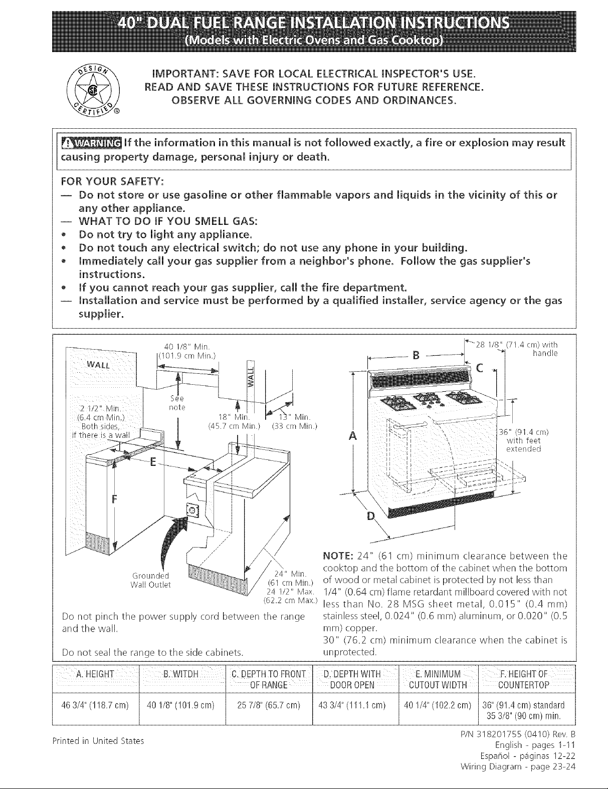
40 1/8" Min.
Min.
(45.7 crn Min.) (33 cm Min.)
if there is a wall A
, 36" (91,4 cm)
!_ with feet
extended
NOTE: 24" (61 cm) minimum clearance between the
\
Grounded 24" Min.
Wall Outlet (61 cm Min.)
24 1/2" Max.
(62.2 cm Max,)
Do not pinch the power supply cord between the range
and the wall.
cooktop and the bottom of the cabinet when the bottom
of wood or metal cabinet isprotected by not lessthan
1/4" (0.64 cm) flame retardant millboard covered with not
less than No. 28 MSG sheet metal, 0.015" (0.4 ram)
stainless steel, 0.024" (0.6 ram) aluminum, or 0.020" (0.5
ram) copper.
30" (76.2 cm) minimum clearance when tile cabinet is
Do not seal the range to the side cabinets.
unprotected.
C: DEPTHTOFRONT D, DEPTHWITH E,MINIMUM ' F.HEIGHTOF
, , OFRANGE ' DOOROPEN CUTOUTWIDTH COUNTERTOP
463/4"(118.7cm) 40 1/8"(101.9cm) 257/8"(65.7cm) 43 3/4"(111.1crn) 401/4"(102.2cm) 36"(91.4cm)stalsdard
353/8"(90cm) rain.
Printed in United States
P/N 318201755 (0410) Rev
English - pages 1-11
EspaPiol - p_iginas 12-22
Wiring Diagram - page 23-24
Page 2
Important Notes to the _nstaIIer
1. Read all instructions contained in these installation
instructions before installing range.
2. Remove all packing material from the oven
compartments before connecting the electrical supply
to the range (see "Preparation ", page 8).
3. Install the4 shipping bolts from range
packaging as range leveling legs (see "Leveling the
Range", page 8).
4. Two anti-tip brackets MUST be removed from
lower back of range and MUST be installed (see
"Anti-tip Bracket Installation", page I0).
5. Observe all governing (:odes and ordinances.
6. Besure to leave these instructions with the consumer.
Important Note to the Consumer
Keep these instructions with your owner's guide for future
reference.
IMPORTANT SAFETY
iN<. NS
Installation of this range must conform with local codes
or, in the absence of local codes, with the National Fuel
Gas Code ANS! Z223. lqatest edition.
This range has been designed certified by tile American
Gas Association. As with any appliance using gas and
generating heat, there are certain safety precautions you
should follow. You will find them in the Use and Care
Guide, read it carefully.
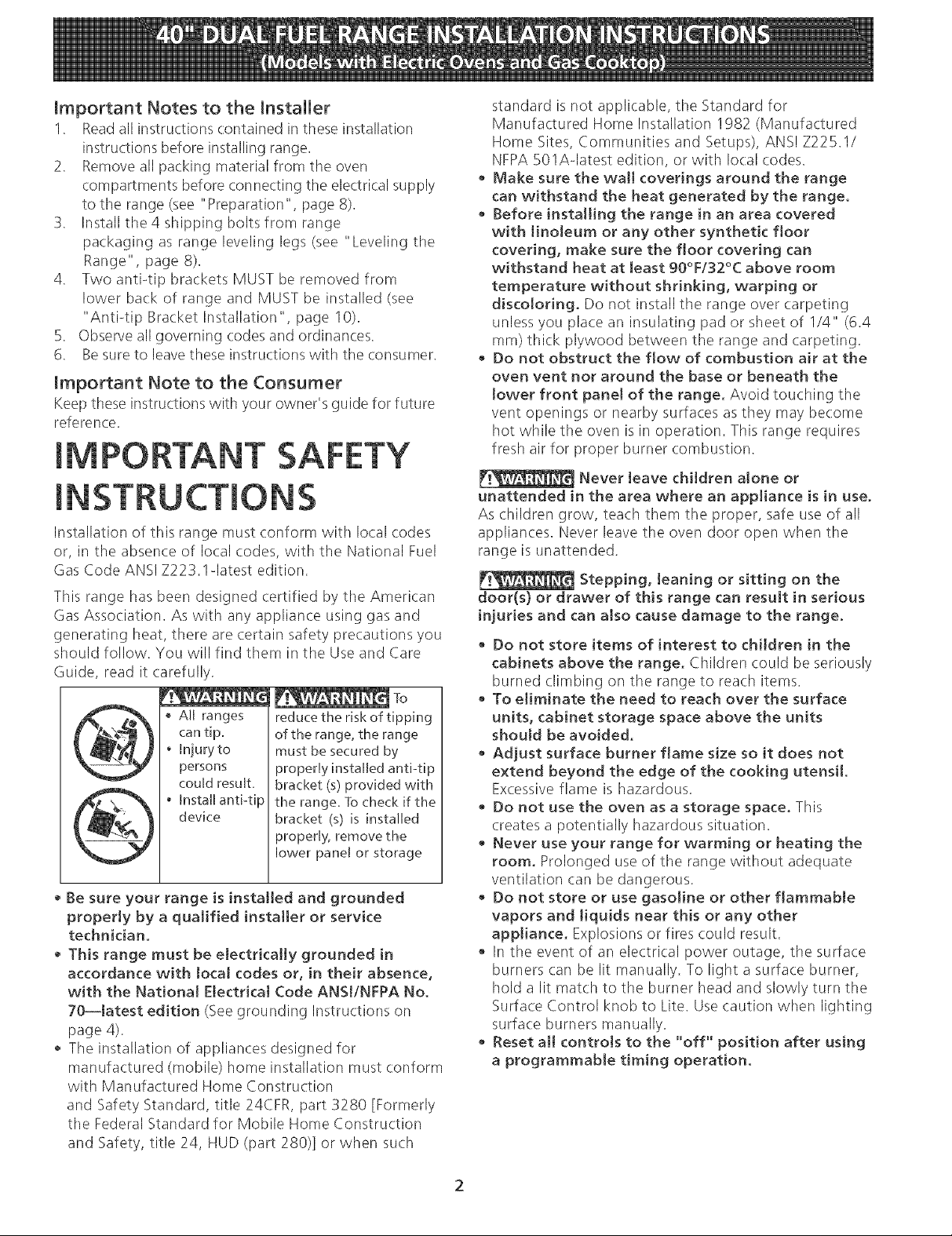
_'_'_'_ To
AIJranges
cantip.
• Injury to
persons
couJdresuk.
• InstalB anti-tip
device
• Be sure your range is installed and grounded
properly by a qualified installer or service
technician.
• This range must be electrically grounded in
accordance with tocal codes or, in their absence,
with the Nationa[ Electrical Code ANS[/NFPA No.
7O--]atest edition (See grounding Instructions on
page 4).
• Tile installation of appliances designed for
manufactured (mobile) home installation must conform
with Manufactured Home Construction
and Safety Standard, title 24CFR, part 3280 [Formerly
tile Federal Standard for Mobile Home Construction
and Safety, title 24, HUD (part 280)] or when such
reduce the risk of tipping
of the range, the range
must be secured by
properly installed anti-tip
bracket (s) provided with
the range, To check if the
bracket (s) is installed
properly, remove the
lower panel or storage
standard is not applicable, the Standard for
Manufactured Home Installation 1982 (Manufactured
Home Sites, Communities and Setups), ANS! Z225.1/
NFPA 501Aqatest edition, or with local codes.
• Make sure the wall coverings around the range
can withstand the heat generated by the range.
• Before installing the range in an area covered
with linoleum or any other synthetic floor
covering, make sure the floor covering can
withstand heat at [east 90°F/32°C above room
temperature without shrinking, warping or
discoloring. Do not install the range over carpeting
unless you place an insulating pad or sheet of I/4" (6.4
ram) thick plywood between the range and carpeting.
• Do not obstruct the flow of combustion air at the
oven vent nor around the base or beneath the
tower front paneJ of the range. Avoid touching the
vent openings or nearby surfaces as they may become
hot while the oven is in operation. This range requires
fresh air for proper burner combustion.
Never leave children alone or
unattended in the area where an appliance is in use.
As children grow, teach them the proper, safe use of all
appliances. Never leave the oven door open when the
range is unattended.
Stepping, leaning or sitting on the
door(s) or drawer of this range can result in serious
injuries and can also cause damage to the range,
• Do not store items of interest to children in the
cabinets above the range. Children could be seriously
burned climbing on the range to reach items.
To e[iminate the need to reach over the surface
units, cabinet storage space above the units
should be avoided.
Adjust surface burner flame size so it does not
extend beyond the edge of the cooking utensil.
Excessive flame is hazardous.
• Do not use the oven as a storage space. This
creates a potentially hazardous situation.
• Never use your range for warming or heating the
room. Prolonged use of the range without adequate
ventilation can be dangerous.
• Do not store or use gasoline or other flammable
vapors and liquids near this or any other
appliance. Explosions or fires could result.
• In the event of an electrical power outage, the surface
burners can be lit manually. To light a surface burner,
hold a lit match to the burner head and slowly turn the
Surface Control knob to Lite. Use caution when lighting
surface burners manually.
• Reset aH controls to the "off" position after using
a programmable timing operation.
Page 3
Power Supply Cord Kit
Tile user is responsible for connecting tile power supply
cord to the connection block located behind the back
panel access cover.
This appliance may be connected by means of
permanent "hard wiring" (flexible armored or
nonmetallic shielded copper cable), or by means of a
power supply cord kit. Use only a power supply cord kit
rated at 125/250 volts minimum, 40 amperes minimum
and marked for use with ranges. See chart (below) for
cord kit connection opening size and rating information.
Cord must have either 3 or 4 conductors.
For mobile homes, new installations, recreational
vehicles, or areas where local codes do not permit
grounding through neutral, a 4 conductor power supply
cord kit rated at 125/250 volts minimum, 40 amperes
and marked for use with ranges should be used (see
Figure 4).
Terminals on end of wires must either be closed loop or
open-end spade lugs with upturned ends. Cord must
have strain relief clamp.
Risk of fire or electrical shock exists if
an incorrect size range cord kit is used, if the
Installation Instructions are not followed, or [f the
strain relief bracket is discarded,
Range Connection Opening Size Chart
Refer to chart below for proper range connection opening size
and power supply cord kit ampere rating information See serial
plate on range for kilowatt rating data.
Range Kilowatt Rating
(See Serial Plate on Range)
I20/240 Volts 120/208 Volts
0-16.5 kW 0 -12,5 kW
I6,6-22.5kW 12.6-18,5kW
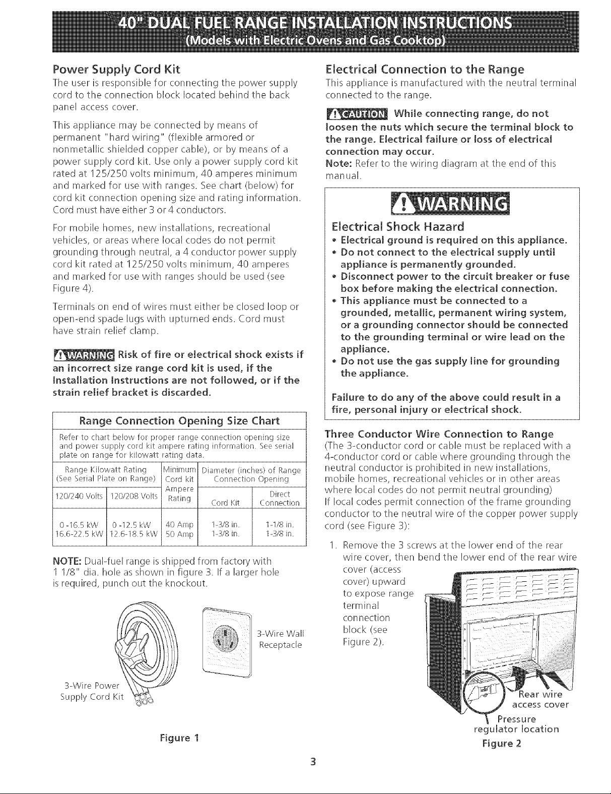
NOTE: Dual-fuel range isshipped from factory with
1 1/8" dia. hole as shown in figure 3. If a larger hole
is required, punch out the knockout.
Minimum Diameter (inches) of Range
Cord kit Connection Opening
Ampere Direct
Rating Cord Kit Connection
40 Amp 1-:_/8 in. 1-I/8 in,
50 Amp 1-3/8 in. 1-3/8 in
3-Wire Wall
Receptacle
Electrical Connection to the Range
This appliance is manufactured with the neutral terminal
connected to the range.
While connecting range, do not
loosen the nuts which secure the terminal block to
the range. Electrical failure or loss of electrical
connection may occur.
Note: Refer to the wiring diagram at the end of this
manual.
Electrical Shock Hazard
• Electrical ground is required on this appliance.
Do not connect to the electrical supply until
appliance is permanently grounded.
• Disconnect power to the circuit breaker or fuse
box before making the electrical connection.
This appliance must be connected to a
grounded, metallic, permanent wiring system,
or a grounding connector should be connected
to the grounding termina[ or wire tead on the
appliance.
• Do not use the gas supply line for grounding
the appliance.
Failure to do any of the above could result in a
fire, personal injury or electrical shock.
Three Conductor Wire Connection to Range
(The 3<:onductor cord or (:able must be replaced with a
4<onductor cord or cable where grounding through the
neutral conductor is prohibited in new installations,
mobile homes, recreational vehicles or in other areas
where local codes do not permit neutral grounding)
If local codes permit connection of the frame grounding
conductor to the neutral wire of the copper power supply
cord (see Figure 3):
1. Remove the 3 screws at the lower end of tile rear
wire cover, then bend tile lower end of the rear wire
cover (access
cover) upward
to expose range
terminal
connection
block (see
Figure 2).
3-Wire Powe_
Supply Cord Kit
Figure 1
_ear wi re
access cover
Pressure
regulator location
Figure 2
Page 4
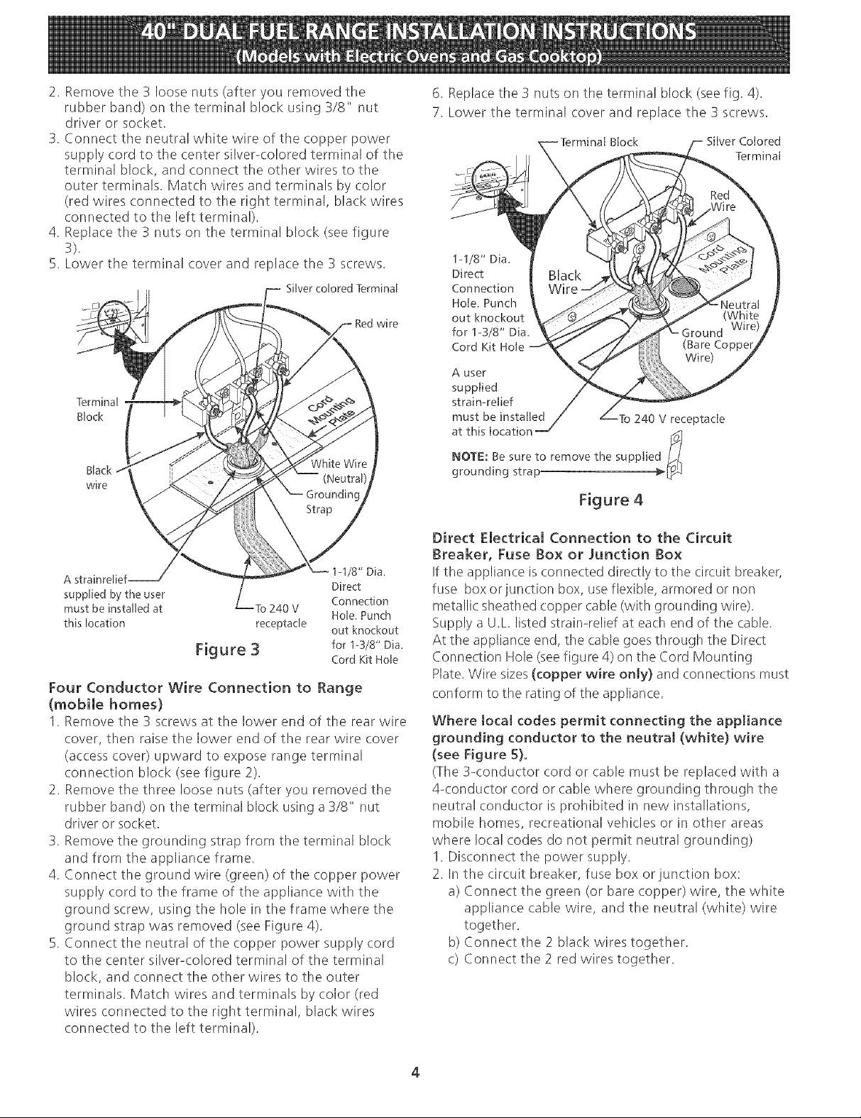
2. Remove the 3 loose nuts (after you removed the
rubber band) on the terminal block using 3/8" nut
driver or socket.
3. Connect the neutral white wire of the copper power
supply cord to the center silver-colored terminal of tile
terminal block, and connect the other wires to the
outer terminals. Match wires and terminals by color
(red wires connected to the right terminal, black wires
connected to the left terminal).
4. Replace tile 3 nuts on tile terminal block (see figure
3).
5. Lower the terminal cover and replace the 3 screws.
Silver colored Terminal
Black
wire
wire
6. Replace the 3 nuts on the terminal block (seefig. 4).
7. Lower the terminal cover and replace the 3 screws.
Block Silver Colored
Terminal
1-1/8" Dia.
Direct
Connection
Hole. Punch
out knockout
for 1-3/8" Dia.
Cord Kit Hole
A user
supplied
strain-relief
must be installed To 240 V receptacle
NOTE: Be sure to remove the supplie
at this location I_t
grounding strap
A strainrelief Direct
supplied by the user
must be installed at To 240 V
this location receptacle out knockout
Figure 3 for 1-3/8" Dia.
/8" Dia.
Connection
Hole. Punch
Cord Kit Hole
Four Conductor Wire Connection to Range
(mobile homes)
1. Remove the 3 screws at the lower end of the rear wire
cover, then raise the lower end of the rear wire cover
(access cover) upward to expose range terminal
connection block (see figure 2).
2. Remove the three loose nuts (after you removed the
rubber band) on the terminal block using a 3/8" nut
driver or socket.
3. Remove the grounding strap from the terminal block
and from the appliance frame.
4. Connect the ground wire (green) of the copper power
supply cord to the frame of the appliance with the
ground screw, using the hole in the frame where the
ground strap was removed (see Figure 4).
5. Connect the neutral of the copper power supply cord
to the center silver-colored terminal of the terminal
block, and connect the other wires to the outer
terminals. Match wires and terminals by color (red
wires connected to the right terminal, black wires
connected to the left terminal).
Direct Electrical Connection to the Circuit
Breaker, Fuse Box or Junction Box
If the appliance is connected directly to the circuit breaker,
fuse box or junction box, useflexible, armored or non
metallic: sheathed copper cable (with grounding wire).
Supply a U.L listed strain-relief at each end of the cable.
At the appliance end, the cable goes through the Direct
Connection Hole (seefigure 4) on the Cord Mounting
Plate. Wire sizes(copper wire only} and connections must
conform to the rating of the appliance.
Where tocaJ codes permit connecting the appliance
grounding conductor to the neutral (white) wire
(see Figure 5)°
(The 3-conductor cord or cable must be replaced with a
4-conductor cord or cable where grounding through the
neutral conductor is prohibited in new installations,
mobile homes, recreational vehicles or in other areas
where local codes do not permit neutral grounding)
1. Disconnect the power supply.
2. In the circuit breaker, fuse box or junction box:
a) Connect the green (or bare copper) wire, the white
appliance cable wire, and the neutral (white) wire
together.
b) Connect the 2 black wires together.
c) Connect the 2 red wires together.
4
Page 5
White Wire
(Neutram)
Cabmefrom
Residence
Black
Wires 1
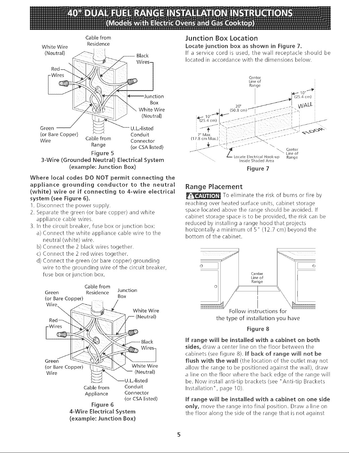
Junction Box Location
Locate junction box as shown in Figure 7.
If a service cord is used, the wall receptacle should be
located in accordance with the dimensions below.
Center
Line of
Range
tion
Box
White Wire
(Neutral)
Green -- U.L.disted
(or Bare Copper) Conduit
Wire Cable from Connector
Range (or CSA misted)
Figure 5
3-Wire (Grounded Neutral) Electrical System
(example: Junction Box)
Where local codes DO NOT permit connecting the
appliance grounding conductor to the neutral
(white) wire or if connecting to 4-wire electrical
system (see Figure 6).
1. Disconnect the power supply.
2. Separate the green (or bare copper) and white
appliance cable wires.
3. In the circuit breaker, fuse box or junction box:
a) Connect the white appliance cable wire to the
neutral (white) wire.
b) Connect the 2 black wires together.
c) Connect the 2 red wires together.
d) Connect the green (or bare copper) grounding
wire to the grounding wire of the circuit breaker,
fuse box or junction box.
Cabmefrom
Green Residence Junction
(or Bare Copper) Box
Wit
White Wire
,4 cm)
lO"
(so. m) [ ._<s--" _?
07.8 Max.)l egg _H: :........
: 22 .....
Z" L _ Center
....... Inside Shaded Area
ocate Electrical Hook up Range
Figure 7
Line of
Range Placement
To eliminate the risk of burns or fire by
reaching over heated surface units, cabinet storage
space located above the range should be avoided. If
cabinet storage space is to be provided, the risk can be
reduced by installing a range hood that projects
horizontally a minimum of 5" (12.7 cm) beyond the
bottom of the cabinet.
Center
Line of
Range
Follow instructions for
the type of installation you have
Wires
Green
(or Bare Copper)
Wire
4-Wire Electrical System
(example: Junction Box)
White Wire
(Neutral)
U.L.qisted
CabNefrom Conduit
Appmiance Connector
(or CSA misted)
Figure 6
Figure 8
Jf range will be installed with a cabinet on both
sides, draw a (:enter line on the floor between the
cabinets (see figure 8). If back of range will not be
flush with the wall (the location of the outlet may not
allow the range to be positioned against the wall), draw
a line on the floor where the back edge of the range will
be. Now install anti-tip brackets (see "Anti-tip Brackets
Installation", page 10).
Jf range will be installed with a cabinet on one side
only, move the range into final position. Draw a line on
the floor along the side of the range that is not against
Page 6
tilecabinet.If backof rangewill not beflushwith
thewall (thelocationof theoutletmaynotallowthe
rangetobepositionedagainstthewall),drawa lineon
thefloorwherethebackedgeoftherangewill be.Now
installanti-tipbrackets(see"Anti-tipBrackets
Installation",page10).
tf rangewill not beinstalledagainstacabinet,
moverangeintofinalposition.Drawalineonthefloor
alongbothsidesoftherange,tf backof rangewill not
beflushwith the wall (thelocationoftheoutletmay
notallowtherangeto bepositionedagainstthewall),
drawalineonthefloorwherethebackedgeofthe
rangewillbe.Nowinstallanti-tipbrackets(see"Anti-tip
BracketsInstallation",page10).
Thesupplylineshouldbeequippedwithanapproved
shutoffvalve(seeFigure9).Thisvalveshouldbelocated
inthesameroomastherangeandshouldbeina
locationthatallowseaseofopeningandclosing.Donot
blockaccesstotheshutoffvalve.Thevalveisforturning
onorshuttingoff gastotheappliance.Opentheshutoff
valveinthegassupplyline.Waitafewminutesforgas
tomovethroughthegasline.
Thegassupplybetweentheshutoffvalveandthe
regulatormaybeconnectedbyrigidpipingor byA.G.A./
C.G.A.-approvedflexiblemetallicunionconnected
pipingwherelocalcodespermituse.
Thegassupplypipingcanbethroughthesidewallof
therightcabinet.Therightsidecabinetisanideal
locationforthemainshutoffvalve.
Donotmaketheconnectiontootight.
Theregulatorisdiecast.Overtighteningmaycrackthe
regulatorresultinginagasleakandpossiblefireor
explosion.
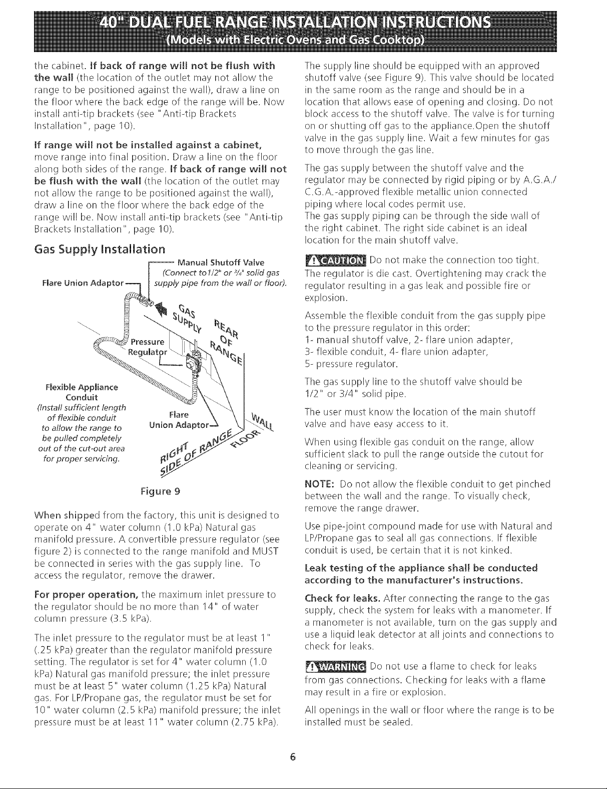
Assembletheflexibleconduitfromthegassupplypipe
tothepressureregulatorinthisorder:
1-manualshutoffvalve,2-flareunionadapter,
3-flexibleconduit,4-flareunionadapter,
5-pressureregulator.
Figure9
Whenshippedfromthefactory,thisunitisdesignedto
operateon4" watercolumn(1.0kPa)Naturalgas
manifoldpressure.Aconvertiblepressureregulator(see
figure2)isconnectedtotherangemanifoldandMUST
beconnectedinserieswiththegassupplyline.To
accesstheregulator,removethedrawer.
Forproperoperation,themaximuminletpressureto
theregulatorshouldbenomorethan14"ofwater
columnpressure(3.5kPa).
TheinletpressuretotheregulatormustbeatleastI "
(.25kPa)greaterthantheregulatormanifoldpressure
setting.Theregulatorissetfor4" watercolumn(I.0
kPa)Naturalgasmanifoldpressure;theinletpressure
mustbeatleast5" watercolumn(1.25kPa)Natural
gas.ForLP/Propanegas,theregulatormustbesetfor
10"watercolumn(2.5kPa)manifoldpressure;theinlet
pressuremustbeatleast11" watercolumn(2.75kPa).
Thegassupplylinetotheshutoffvalveshouldbe
1/2"or3/4"solidpipe.
Theusermustknowthelocationofthemainshutoff
valveandhaveeasyaccessto it.
Whenusingflexiblegasconduitontherange,allow
sufficientslacktopulltherangeoutsidethecutoutfor
cleaningorservicing.
NOTE:Donotallowtheflexibleconduittogetpinched
betweenthewallandtherange.Tovisuallycheck,
removetherangedrawer.
Usepipe-jointcompoundmadeforusewithNaturaland
LP/Propanegastosealallgasconnections.Ifflexible
conduitisused, be certain that it is not kinked.
Leak testing of the appliance shah be conducted
according to the manufacturer's instructions.
Check for Jeaks. After connecting the range to the gas
supply, check the system for leaks with a manometer. If
a manometer is not available, turn on the gas supply and
use a liquid leak detector at all joints and connections to
check for leaks.
Do not use a flame to check for leaks
from gas connections. Checking for leaks with a flame
may result in a fire or explosion.
All openings in the wall or floor where the range is to be
installed must be sealed.
Page 7
Tightenallconnectionsif necessaryto preventgas
leakageinthecooktopor supplyline.
Checkalignmentof valvesafterconnectingthe
cooktoptothegassupplyto besurethemanifoldpipe
hasnotbeenmoved.
Disconnectthe rangeandits individualshutoff
valvefromthegassupplypipingsystemduringany
pressuretestingofthesystemattestpressuresgreater
than1/2psig(3.5kPaor14"watercolumn).
LP/PropaneGasConversion
ThisappliancecanbeusedwithNaturalGasorPropane
Gas.Itisshippedfromthefactoryforusewithnaturalgas.
IfyouwishtoconvertyourrangeforusewithLP/Propane
gas,usethesuppliedfixedorifices;theyarecontainedina
specialbagalongwithinstructionsmarked"FORLP/
PROPANEGASCONVERSION",locatedonthebackof
therange,doseto theapplianceregulatorvalve.
Theconversionmustbeperformedbyaqualifiedinstaller,
LPsupplierorservicetechnicianinaccordancewiththe
installationinstructionsfurnishedwiththisrangeandall
codesandrequirementsofalllocalcodesand
requirements.Failuretofollowinstructionscouldresultin
seriousinjuryorpropertydamage.Thequalifiedagency
performingthisworkassumesresponsibilityforthe
conversion.
Moving the Appliance for
Servicing and Cleaning
Turn off the range line fuse or circuit breakers at the
main power source, and turn off the manual gas shut-off
valve. Make sure the range is cold. Remove the service
drawer and open the oven door. Lift the range at the
front and slide it out of the cut-out opening without
creating undue strain on the flexible gas conduit.
tsolate the range from the gas supply piping system
by closing its individual manual shutoff valve during any
pressure testing of the gas supply piping system at test
pressures equal to or less than 1/2 psig (3.5kPa or 14"
water column).
Make sure not to pinch the flexible gas conduit at the
back of the range when replacing the unit into the cut-
out opening. Replace the drawer, close the door and
switch on the electrical power and gas to the range.
If the pressure regulator is connected to rigid piping, tile
regulator must be disconnected before moving the
appliance.
Reassemble in reverse order (see figure 9).
Failure to make the appropriate conversion
can result in personal injury and property damage.
_Any additions, changes or conversions
required in order for this appliance to satisfactorily meet
the application needs must be made by an authorized
SearsService Center, Distributor or Qualified Agency.
Page 8
Range Installation
When unpacking the range, do not
discard the 4 shipping bolts, These are to be replaced on
the unit for use as leveling legs and height adjustments.
NOTE:
1. The back of the range may be installed directly
against the wall.
2. To reduce possible scorching of vertical walls and to
minimize potential fire hazards under abnormal
surface unit use conditions such as high heat or no
pans and to conform to A.G.A. requirements, a
minimum of 2 I/2" (6.4 cm) spacing should be
provided on both sides of the cooktop.
Excessive Weight Hazard
e Use 2 or more people to move and install
range,
• Failure to follow this instruction can result in
back or other injury,
.
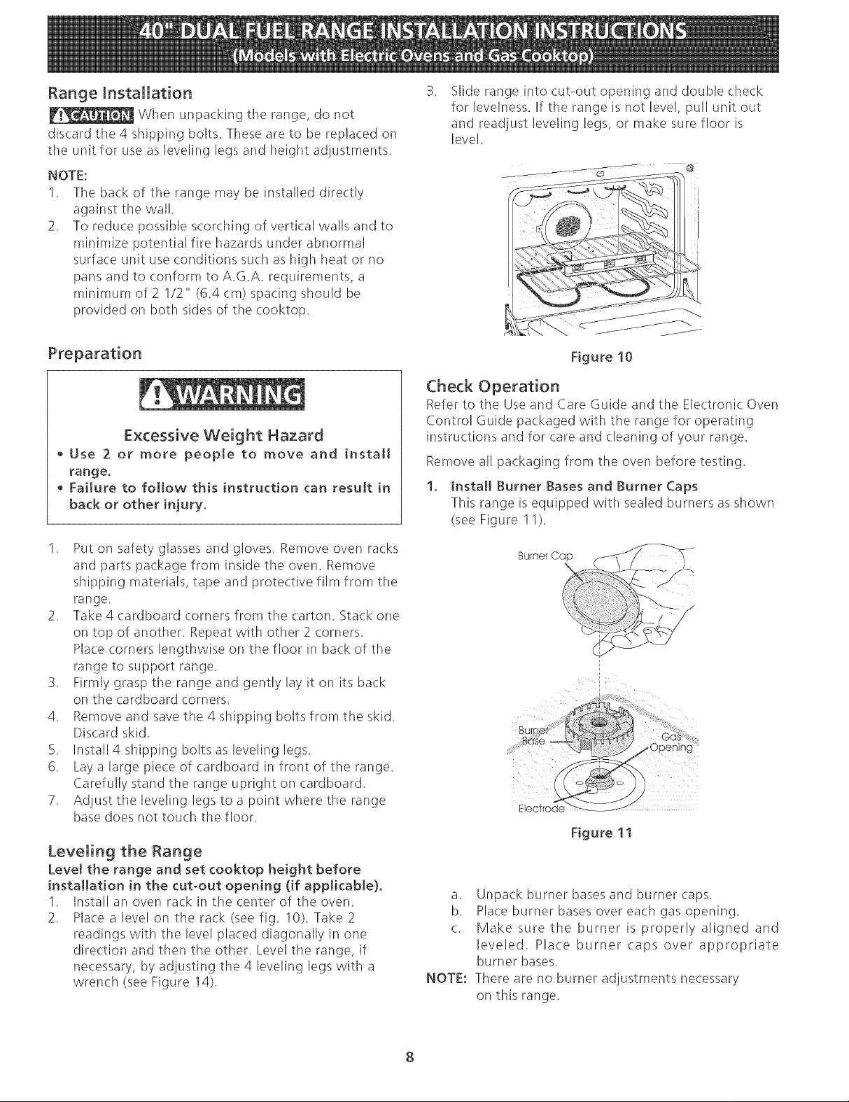
Slide range into cut-out opening and double check
for levelness. If the range is not level, pull unit out
and readjust leveling legs, or make sure floor is
level.
Figure 10
Check Operation
Refer to the Use and Care Guide and the Electronic Oven
Control Guide packaged with the range for operating
instructions and for care and cleaning of your range.
Remove all packaging from the oven before testing.
1. Install Burner Bases and Burner Caps
This range is equipped with sealed burners as shown
(see Figure 11).
I. Put on safety glasses and gloves. Remove oven racks
and parts package from inside the oven. Remove
shipping materials, tape and protective film from the
range.
2. Take 4 cardboard corners from the carton. Stack one
on top of another. Repeat with other 2 corners.
Place corners lengthwise on the floor in back of tile
range to support range,
3. Firmly grasp the range and gently lay it on its back
on the cardboard corners,
4. Remove and save the 4 shipping bolts from the skid.
Discard skid,
5. Install 4 shipping bolts as leveling legs,
6. Lay a large piece of cardboard in front of the range.
Carefully stand the range upright on cardboard.
7. Adjust the leveling legs to a point where the range
base does not touch the floor.
Leveling the Range
Level the range and set cooktop height before
installation in the cut-out opening (if applicable).
1. Install an oven rack in the center of the oven.
2. Place a level on the rack (see fig. 10). Take 2
readings with the level placed diagonally in one
direction and then the other. Level the range, if
necessary, by adjusting the 4 leveling legs with a
wrench (see Figure 14).
Burner Cap (
EecTfoae
Figure 11
a. Unpack burner bases and burner caps.
b. Place burner bases over each gas opening.
c. Make sure the burner is properly aligned and
leveled. Place burner caps over appropriate
burner bases.
NOTE: There are no burner adjustments necessary
on this range.
8
Page 9

2.
Turn on Electrkat Power and Open Main Shutoff
Gas Valve
3.
Check the Igniters
Operation of electric igniters should be checked after
range and supply line connectors have been carefully
checked for leaks and range has been connected to
electric power. To check for proper lighting:
a. Push in and turn a surface burner knob to the
LITEposition. You will hear the igniter sparking.
b. Tile surface burner should light when gas is
available to the top burner. Each burner should
light within four (4) seconds in normal operation
after air has been purged from supply lines.
Visually check that burner has lit.
c. Once the burner lights, the control knob should
be rotated out of the LITEposition.
There are separate ignition devices for each burner.
Try each knob separately until all burner valves have
been checked.
.
Adjust the "LOW" Setting of Surface Burner
Valves (see Figure 12)
a. Push in and turn each control to LITEuntil burner
ignites.
b. QukMy turn knob to LOWESTPOSITION.
c. If burner goes out, readjust valve as follows:
Reset control to OFF. Remove tile surface burner
control knob, insert a thin-bladed screwdriver
into the hollow valve stem and engage the
slotted screw inside. Flame size (:an be increased
or decreased with tile turn of the screw. Adjust
flame until you (:an quickly turn knob from LITE
to LOWEST POSITIONwithout extinguishing the
flame. Flame should be as small as possible
without going out,
5. Operation of Oven Elements
The oven isequipped with an electronic oven control. Each
of the functions has been factory checked before shipping.
However, it issuggested that you verify the operation of
the electronic oven controls once more. Refer to the Use
and Care Guide for operation. Follow the instructions for
the Clock, Timer, Bake, Broil, Convection (some models)
and Clean (some models) functions.
When checking oven element operation,
do not touch the elements. They will be hot enough to
cause serious burns.
Bake-After setting the oven to 350% (I 77°C) for baking,
the lower element in the oven should become red.
Broil-When tile oven isset to BROIL, the upper element
in tile oven should become red.
Clean (some models}-When the oven is set for a self-
cleaning cycle, the upper element should become red
during the preheat portion of the cycle. After reaching
the self-cleaning temperature, the lower element will
become red.
Convection (some modeJs)-When the oven is set to
CONV. BAKE/ROAST at 350% (177°C), both elements
cycle on and off alternately and the convection fan will
turn. The convection fan will stop turning when the oven
door isopened during convection baking or roasting.
When All Hookups are Complete
Make sure all controls are left in the OFFposition.
Model and Serial Number Location
Tile serial plate is located on the drawer side frame.
When ordering parts for or making inquiries about your
range, always be sure to include the model and serial
numbers and a lot number or letter from the serial plate
on your range.
Before You Call for Service
Read the Avoid Service Checklist and operating
instructions in your Use and Care Guide. It may save you
time and expense. Tile list includes common occurrences
that are not the result of defective workmanship or
materials in this appliance.
Refer to the warranty and service information in your Use
and Care Guide for our phone number and address.
Please (:all or write if you have inquiries about your
range product and/or need to order parts.
Page 10

Important Safety Warning
To reduce the risk of tipping of the range, the range
must be secured to the floor by properly installed antPtip
brackets and screws packed with the range. Those parts
are located in a plastic bag in the oven. Failure to install
tile antPtip brackets will allow the range to tip over if
excessive weight is placed on an open door or if a child
climbs upon it. Serious injury might result from spilled
hot liquids or from the range itself.
Follow the instructions below to install the antPtip
brackets.
If range is ever moved to a different location, the antPtip
brackets must also be moved and installed with the
range. To check for proper installation, see step 5.
Tools Required:
5/16" (8 ram) Nutdriver or Flat Head Screwdriver
Adjustable Wrench
Electric Drill
3/16" (4.8 ram) Diameter Drill Bit
3/16" (4.8 ram) Diameter Masonry Drill Bit (if installing
in concrete)
Antiotip Bracket Installation
Brackets attach to the floor at the back of the range to
hold both rear leg levelers. When fastening to the floor,
be sure that screws do not penetrate electrical wiring or
plumbing. The screws provided will work in either wood
or concrete.
1. Unfold paper template and place it flat on the floor
with the back and side edges positioned exactly
where the back and sides of range will be located
when installed. (Use the diagram in figure 13 to
locate brackets if template is not available.)
2. Mark on the floor the location of the 4 mounting
holes (2 holes per bracket) shown on the template.
For easier installation, 3/16" (4.8 ram) diameter pilot
holes 1/2" (1.3 cm) deep can be drilled into the
floor.
3. Remove template and place brackets on floor with
turned up flanges to the outside (see figure !3). Line
up holes in brackets with marks on floor and attach
with 4 screws provided (2 screws per bracket).
Brackets must be secured to solid floor. If attaching
to concrete floor, first drill 3/16" (4.8 ram) dia. pilot
holes using a masonry drill bit.
4. Level range if necessary, by adjusting the 4 leveling
legs with a wrench. (See Figure 14 below.) A
minimum clearance of 1/8" (3.2 ram) is required
between the bottom of the range and the rear
leveling legs to allow room for the anti4ip brackets.
5. Slide range into place making sure rear legs are
trapped by ends of brackets. Range may need to be
shifted slightly to one side as it is being pushed back
to allow rear legs to align with brackets.
6. After installation, verify that the anti4ip bracket is
engaged. Open and remove drawer and check to
make sure the antPtip bracket is engaged.
il
AntPtip Bracket
Figure 13
_Slide Back
Sides of
range
Figure 14
10
Page 11

NOTES:
I I
Page 12

iMPORTANTE: GUARDE ESTAS iNSTRUCCIONES PARA USO DEL
iNSPECTOR LOCAL DE ELECTRICmDAD.
LEA Y GUARDE ESTAS iNSTRUCCIONES PARA REFERENCIA FUTURA.
OBSERVE CODIGOS TODO GOBERNANTES Y ORDENANZAS.
IF_Si ia informaci6n contenida en este manual no es seguida e×actamente, puede
ocurrir un incendio o expiosi6n causando daSos materiaies, lesi6n personal o la muerte.
PARA SU SEGUR[DAD:
-- No almacene ni utilice gasolina u otros vapores y [iquidos inflamables en [a proximidad de _ste
o de cuaiquier otto artefacto.
-- QUE DEBE HACER Sl PERCIBE OLOR A GAS:
• No trate de encender ningQn artefacto.
® No toque ningQn interruptor el_ctrico; no use ningQn tel_fono en su edificio.
• Llamea su proveedor de gas desdeeitel_fono de un vecino. Siga las instrucciones dei
proveedor de gas.
• Si no logra comunicarse con su proveedor de gas, liame ai departamento de bomberos.
-- La instaiad6n y el servicio de mantenimiento deben set efectuados pot un instaiador caiificado,
la agencia de servicio o el proveedor de gas.
40 I/8" Min.
01.9 cm Min.)
Wa
2 I/2'! Mln, Nota
18" Min. 13" Min.
Si hay uno (45,7 cm Min.) (33 cm Min.) A
lados
\
Tomacorriente de 24" Min.
pared puesto a tierra (61 cm Min.)
No pellizque el cord6n electrico entre la estufa y la
pared,
No selle la estufa a los armarios de lado,
A.ALTURA E ANCHURA C,PROFUNDIDADAL
FRENTEDELAESTUFA
24 I/2" Max
(62,2 cm Max,)
D.PROFUNDIDADCONE=MiNIMODEANCHO
D
\
**NOTA: Un espacio minimo de 24" (61 cm) entre la
superficie de la estufa y e! fondo de! armario cuando e!
fondo de! armario de madera o metal estA protegido por
no menos de 1/4" (0.64 cm) de madera resistente al fuego
cubierta por una la'mina met_lica de MSG, nOmero 28,
0,015" (0,4 ram) de acero inoxidable, 0,024" (0.6 mm) de
aluminio, 6 0,02" (0,5 ram) de cobre.
Un espacio minimo de 30" (76.2 cm) cuando el armario no
esta' protegido,
PUERTAABIERTA ESPACiORECORTADO
MOSTRADOR
46 3/4"(!18.7 crn) 401/8"(101.9cm) 257/8"(65.7cm)
Imprimido en los Estados Unidos
43 3/4"(111.1cm) 40 1/4"(102.2cm)
P/N318201755 (0410) Rew B
Diagrama de la instaJaci6n aJ_imbrica - pagina 23-24
36" (91,4 cm) standard
35 3/8" (90 cm) min.
English - pages 1-11
Espa_ol - paginas 12-22
Page 13

Notas importantes para el Instaiador
1. Lea todas las instrucciones contenidas en este manual
antes de instalar la estufa,
2. Saque todo e! material usado en el embalaje del
compartimiento de! homo antes de conectar el
suministro electrico a la estufa,
3. Guarde los 4 pernos de[ empaque de la estufa
para usar[os como patas nive[adoras.
4. Dos soportes antivuelco DEBEN quitarse de [a
parte de inferior trasera de [a estufa y DEBEN set
insta[ados. Para deta[[es, vea instrucciones en [a
p_gina 10.
5, Observe todos los c6digos y reglamentos pertinentes.
6. Deje estas instrucciones con el comprador,
Nota Importante para el Consumidor
Conserve estas instrucciones y el Manual del Usuario para
referencia futura.
IMPORTANTES
IN NES DE
EGUR[DAD
Instalaci6n de esta estufa debe cumplir con todos los
c6digos locales, o en ausencia de c6digos locales con el
C6digo Naciona! de Gas Combustible ANSI Z223.1--
01tima edici6n,
El disef_o de esta estufa ha sido certificado pot la
Asociaci6n de Gas Americana, En este comoen
cualquier otro artefacto que use gas y genere calor, hay
ciertas precauciones de seguridad que usted debe seguir,
Estas serAn encontradas en el Manual del Usuario, lealo
cuidadosamente.
La instalaci6n de aparatos disefiados para instalaci6n
en casas prefabricadas (m6viles) debe conformar con
el Manufactured Home Construction and Safety
Standard, titulo 24CFR, parte 3280 [Anteriormente el
Federal Standard for Mobil Home Construction and
Safety', titulo 24, HUD (parte 280)] o cuando tal
est_ndar no se aplica, el Standard for Manufactured
Home Installation 1982 (Manufactured Home sites,
Communities and Setups), ANS! Z225,1/NFPA 501A-
edici6n m_s reciente, o con los c6digos locales,
• Asegurese de que el material que recubre las
paredes alrededor de [a estufa, pueda resistir et
caior generado por [a estufa.
Antes de instalar la estufa en un _rea cuyo piso
este recubierto con [inbleo u otto tipo de piso
sintetico, asegurese de que estos puedan resistir
una temperatura de pot Io menos 90°F sobre la
temperatura ambienta[ sin provocar
encogimiento, deformaci6n o decoloraci6n. No
instate la estufa sobre una alfombra al menos que
coloque una plancha de material aislante de pot Io
menos 1/4 pulgada, entre la estufa y la alfombra.
• No obstruya el ftujo de[ aire de combustibn en [a
ventilaci6n de[ homo ni tampoco alrededor de [a
base o debajo de[ panel inferior de[antero de [a
estufa. Evite tocar lasaberturaso areascercanas de
la ventilaci6n, ya que pueden estar muy calientes
duranteelfuncionamientode! homo. La estufa
requiere aire fresco para la combusti6n apropiada de
los quemadores.
W_ Nunca deje niffos solos o
desatendidos en un _rea donde un artefacto est_
siendo usado, A medida que los nif_os crecen,
ensefleles e! uso apropiado y de seguridad para todos los
artefactos. Nunca deje la puerta del homoabierta
cuando la estufa est_ desatendida.
Asegurese de que la estufa sea instalada y
conectada a tierra en forma apropiada por un
instalador calificado o por un t_cnico.
• Esta estufa debe set etectricamente puesta a
tierra de acuerdo con los codigos locales, o en su
ausenda, con el C6digo E[ectrico Nacional ANSI/
NFPA No. 70, u[tima edicion.
_Todas [as
estuffas
pueden
volcarse
Esto podria
resultar en
[esiones
persona[es
Insta[e el
dispositivo
antivuelco que
se ha
empacado
junto con esta
estufa_
Para reducir el riesgo de
que se vuelque laestufa,
hay que asegurarla
adecuadamente
colocandole Los soportes
antivuelco que se
proporcionan Para
comprobar si estos estan
instalados y apretados en
su lugar como se debe, ase
el borde trasero superior de
la estufa ycuidadosamente
inclinela hacia
adelante para asegurar
que la estufa se at/tie.
No se pare, apoye o siente en [as
puertas o cajones de esta estufa pues puede
resultar en serias lesiones y puede tambien causar
daffo a [a estufa.
No a[macene articu[os que puedan interesar a los
niffos en los gabinetes sobre la estufa. Los nff:_os
pueden quemarse seriamente tratando de trepar a la
estufa para alcanzar estos articulos.
• Los gabinetes de a[macenamiento sobre [a estufa
deben set evitados, para eliminar [a necesidad de
tener que pasar sobre los elementos superiores de
la estufa para [[egar a ellos,
Ajuste el tamaffo de la llama de los quemadores
superiores de ta[ manera que esta no sobrepase el
bordede los utensilios decocinar. La llama
excesiva es peligrosa.
No use el homo como espacio de a[macenaje. Esto
crear_ una situaci6n potencialmente peligrosa.
Nunca use la estufa para ca[entar el cuarto, E! uso
prolongado de la estufa sin la adecuada ventilaci6n
puede resultar peligroso.
13
Page 14

No almacene ni utilice gasolina u otros vapores y
[[qu[dos [nflamables en [a prox[m[dad de este o
de cualquier otto artefacto electrko. Puede
provocar incendio o explosion.
En caso de una interrupti6n de! servicio electrico, es
pasible de encender los quemadores de superficie a
mano. Para encender un quemador de suoerficie,
acerque un f6sforo encendido del cabezal de!
quemador, y gire delicadamente el bot6n de control de
superficie a LITE (encendido). Tener cuidado al
encender los quemadores a mano.
Ajuste todos los contro[es a [a posid6n "OFF" (apagada)
despu_s de haber hecho una operation con tiempo
programado.
A[ realizar [a conexi6n de la estufa, no
desaprete [as tuercas que aseguran el alambraje de la estufa al
bloque terminal instalado en [afa'brica, Se puede ocurrir torte de
energia o p6rdida de conexion electrica
Electrico de 3
Alambres FJgura 1
Juego de CordOn ElOctrico
El consumidor tiene [a responsabilidad de conectar el cordon
electrico a[ b[oque de conexi6n ubicado detr_is de [a cubierta
de acceso de[ panel trasero.
Este artefacto puede ser conectado mediante "cableado
rigido" permanente (un cable fexible escudido o un cable de
cobre escudido no met_i[ico) o un "juego de cordon
electrico"_ Se usaM so[amente un juego de cordon e[ectrico
para 125/250 voltios m[nimo, 40 amperios minimo y marcado
para usocon estufas E[juegodecordone[ectricodebetener
3 o 4 conductores
Para las casas sobre ruedas, [as nuevas instaladones, en los
vehiculos de recreacion o en [as _ireas donde los cOdigos
locales no permiten [a conexiOn de[ conductor a tierra a[
neutro, un ensamb[aje de suministro electdco de 4
conductores para estufas, dasificado a 125/250 volqos
m[nimo, 40ampenosminimo, debedeser utilizado (vea
Figura 4).
Los terminales en las puntas de los alambres deben ser de
circuito cerrado o de orejeta de pala punta abierta y con las
puntas vueltas hacia arriba. El cordon debe tener un anc[aje
del cable
_!_ Puede ocurrir riesgo de incendio o
choque e[&ctrico si se usa un juego de cord6n de estufa de
tarnaffo incorrecto, si [as instrucdones de instaIad6n no
son seguidas o si no se usa el anc[aje de[ cable.
Tabla de tamaffo de abertura de conexi6n de cocina
Relerirse a la tab[a de arriba para el tamaflo de abertura de
connexion de codna adecuada, y la information sobre el regimen
de amperios del ensamblaje de cordon de suministro eiedrico.
Vea la plata de serie de [a
cocina para informaciOn
sobre el regim¢,rl de
kilovatio.
120/240 Volts I2(}/208 Volts
0-I6.5 Kw 0-I2.5 Kw
I6,6-22,5Kw 12.6-18.5Kw
Minimo
regim_m de
amperios
de
ensamb[aje
de[ cordon
40 Amp
50 Amp
Diametro (pulgadas) de
abierta de conexiOn de
cocina.
DimensiOn ConexiOn
agujero directo
ConnexiOn
1 3/8 pulg 1 1/8 pulg
I 3/8 pulg 1 3/8 pulg
Conexi6n ElOctrica de la Estufa
Este aparato se fabrica con el terminal neutro conectado
al marco.
Refiere a! diagrama de alambraje de esta cocina al final
de este libreta.
Riesgo de Choque El_ctrico
, Una puesta a tierra est_ requerido en este
aparato,
No [o conecte a [a corriente electrica hasta que
el aparato haya sido puesto a tierra
permanentemente,
, Desconecte [a corriente electrica a [a ca]a de
empaImes antes de hacer [a conexion e[ectrica.
Este aparato debe estar conectado con un
sistema de alambres puesto en tierra, met&[ico
y permanente o un conector de puesta a tierra
debe conectarse al terminal de puesta a tierra
o et a[ambre conductor en el aparato.
La falta de hacer cualquier de [as cosas arriba
podHa resu[tar en un incendio, choque
electrico o [esiones persona[es.
Conexi6n de tres alarnbres de conducci6n a la
estufa
(Un cord6n flexible o cable de 3 conductores debe de set
reemplazado con un cord6n flexible o cable de 4 conducto-
res donde la conexiOn de! conductor a tierra al neutro esta
prohibida en las nuevas instalaciones, las casas sobre
ruedas, los vehfculos de recreacbn o otras _reas donde los
cGdigos locales no permiten la conexiGn a tierra al neutro.)
Si los c6digos locales permiten la conexiOn del conductor
de tierra del marco con el alambre neutro del cord6n
electrico de cobre (vea Figura 3):
NOTA: La estufa bPenergia" viene de fabrica preparada para
fundonar con un hueco de 1 1/8" de diametro come se muestra
en la figura 3, En caso de necesitarse un hueco mas grande retire
la cubierta
Figura 2
14
Cubie ta de acceso
del alambre trasero
Ubkaci6n del
regulador de presi6n
Page 15

1.Quitelostrestornillosenlapartem_isbajadelpanel
trasero,luegolevantelapartem_sbajadelpanel
trasero(lacubiertadeacceso)exponiendoelb!oque
deconexionesdelosterminalesdelaestufa(vea
Figura2).
2.Quintelastrestuercasdesatadas(despuesde
removerlacintadegoma)sobree!bloqueterminal
usandoundestornilladoro unaIlavedecasquillode
318".
3.Conecteelcableneutrodelcord6nelectricodecobre
alterminaldecolordeplataenelcentrodelbloque,
yconectelosotroscabelsalosterminaleslaterales.
Emparejeloscablesy losterminalesseg0nelcolor
(cablesrojosconectadoscone!terminalderecho,
cablesnegrosconectadosconelterminalizquierdo).
4.Bajelacubiertadelterminaly reinstalelostres(3)
tornillos.
5.Bajelacubiertadelterminaly repongalos3tornillos.
ueterminal
31ata
B. Conecte e! alambre neutro (blanco) del cord6n
electrico de cobre al terminal de color de plata en el
centro de! b!oque y conecte los otros alambres al los
terminales laterales. Conecte los alambres y
terminales emparejando los co!ores (los alambres rojos
conectsdos a! terminal derecho, los alambres negros
conectados al terminal izquierdo).
6.Reponga las 3 tuercas sobre el bloque terminal (vea
figura 4).
7. Baje la cubierta de acceso y vuelva a poner los B
tornillos.
Bloque terminal
)lata
1q/8" Dia.
Agujero de la
conexi6n
directa.Retira
la arandeJa
pre-cortada
para !-3/8" Dia.
Agujero
Una arazadera
de reteva
provista debe de
estar instalada a
est_ ubicaci6n
Hacia el 240 V conexi6n directa.
receptaculo Retira Ja arandeta
/8" Dia.
Agujero de ta
pre-cortada para
F[gura 3 1-3/8" Dia. Agujero
Conexi6n de 4 aiambres de conducd6n a [a
estufa (casas m6viles)
1. Quite los tres tornillos en la parte m_qsbaja del panel
trasero, luego levante la parte m_s baja del panel
trasero (la cubierta de acceso) exponiendo e! b!oque
de conexiones de los terminales de la estufa (vea
figura 2).
2. Retire las 3 tuercas (despues de haber removido la
banda de goma) sobre e! b!oque terminal usando un
manguito o destornillador de casquillo de 3/8"
pulgadas.
3. Quite la banda de puesta a tierra de! bloque de los
terminalesyde! marco delartefacto. Retenga el
tornillo de puesta a tierra.
4. Conecte el alambre de puesta a tierra (verde) del
cord6n electrico de cobre a! marco del artefacto con
e! tornillo de puesta a tierra, usando e! agujero en el
marco donde se quit6 el tornillo de puesta a tierra
(vea figura 4).
Una arazadera
de releva provista
debe de estar
instalada a est_q Hacia el 240 V
ubicacion recept_culo
NOTA: Asegurese de quitar la banda de puesta a tierra--_//u/
provista.
F[gura 4
Conexion em_ctrka directa am(ortadrcuito, a ma(aja
de fusibmes o macaja de ernpamrnes
Si el aparato esta conectado directamente al cortacircuito,
a la (aja de fusibles o a la caja de empalmes, use un cable
blindado flexible o no met_lico recubierto de cobre ((:on
alambre a tierra). Provee una abrazadera releva de anclaje
homologo UL a cada extremidad del cable. A la
extremidad del el_ctrodomestico, el cable pase a trav6s del
agujero de la conexiOn directa (yea figura 4) en el cable de
la plata de montaje. El tamaflo de los alambres (a[ambre
de cobre soJamente} y las conexiones deben estar
conforme al regimen del electrodom6stico.
Donde [os cSdigos locales permitan conectar e[
conductor de puesta a tierra de[ e[_ctrodom_stko a[
neutral (b[anco) (yea figura 5):
(Un cord6n flexible o cable de 3 conductores debe de set
reemplazado con un cord6n flexible o cable de 4 conducto-
res donde la conexi6n del conductor a tierra al neutro esta
prohibida en las nuevas instalaciones, las casas sobre
ruedas, los vehiculos de recreaci6n o otras areas donde los
c6digos locales no permiten la conexi6n a tierra al neutro.)
1. Desconecte el suministro el@ctrico.
15
Page 16

En el cortacircuito, la caja de fusibles o la caja de
empalmes
a) Conecte el alambre verde (o cobre desnudo), el
alambre blanco del cable de! electrodom6stico y el
alambre neutral (blanco)juntos.
b) Conecte los dos alambres negros juntos.
c) Conecte los dos alambres rojos juntos.
CabBede ]afuente
Alambre
B[anco
(Neutro)
Amambres--
rojo
AUambres (Neutro)
desnudos :onductor de
o verdes CaMe de Ua (Uistado_CSA)
de amimentaci6n
ade
empaUrnes
AUambre
Bmanco
unidn listado_UL
estufa
Figura 5 _ Sistema emectrko (ejemplo: caja de
empalmes) de 3 a[ambres (a tierra neutral)
Donde los cbdigos locales NO permitan conectar el
conductor de puesta a tierra det electrodomestico al
neutral (blanco), o si est_ conectado con un sistema a
4 alambres {vea figura 6):
1. Desconecte e! suministro electrico
2. Separe el alambre verde (o cobre desnudo) y el
alambre blanco del electrodomestico.
3. En el cortacircuito, la caja de fusibles o la caja de
empalmes.
a. Conecte el alambre blanco del cable del
electrodom6stico a! alambre neutral (blanco).
b. Conecte los 2 alambres negros juntos.
c. Conecte los 2 alambres rojos juntos.
d. Conecte el alambre verde (o de cobre desnudo) de
la puesta a tierra del alambre al alarnbre de
puesta a tierra de! cortacircuito, de la caja de
fusibles o de la caja de empalmes.
Alarnbre Cable de ma fuente Caja de
desnudo o de Mimentacidn empalmes
verde .J_--_J | /
Amambros I_%, I _m "_/" V (Neutro)
rlJ° S_sreS,am
desnudo_o "L-'_ Alambre
verdes _2:_vxx v _ Blanco
estufa uni6n listado-UL
(o listado-CSA)
Figura 6 ° Sistema el_ctrico de 4 alambres
(ejemp[o caja de empalme)
LocMice [a caja de empalmes como se ve en [a Figura 7.
Si se usa un corddn de servicio, e! receptAculo de pared
debe estar Iocalizado segOn las medidas que se indican
abajo.
Situad6n de caja de uni6n
CL
de ]a
estufa
sombreada
Figura 7
Estufa o Emplazamiento
e incendios al tocar superficies sobrecalentadas, se debe
evitar colocar espacio para armarios de almacenamiento
sobre las estufas con elementos al descubierto. Si se
instalan armarios sobre la estufa, se pueden reducir tales
riesgos instlando una campana purificadora que se
proyecta horizontalemente un minimo de 5" (12.7 cm)
ma's afuera de la parte inferior de los armarios.
para el tipo de instalaci6n que usted tenga
Si la estufa se va a instalar con un armario a ambos
lados, marque el centro de la abertura de! armario en el
piso. Si la partetrasera de la estufa noestar_ a ras
con la pared (la ubicacidn del tomacorriente puede que
no permita que la estufa se pegue a ras con la pared),
marque e! piso donde estar_i el border trasero de la
estufa. Pongael patrdn en e! piso, alineando la Ilnea
del centro del patrdn con la marca en el centro de la
abertura delarmario. Pongae! bordetrasero del patrdn
a ras contra la pared trasera o la Ilnea marcada para la
parte de atra's de la estufa.
Si la estufa se va a instMar con un armario a sdlo un
lado, mueva la estufa a su posicidn final. Marque el piso
per el lado de la estufa que no estar_ contra el armario.
Si la parte trasera de la estufa no estar_ a ras con la
pared (la ubicacidn de! tomacorriente puede que no
permita que la estufa se pegue a ras con la pared),
marque el piso donde e! borde trasero de la estufa estar_.
Ponga el patrdn en el piso y alinie e! lado del patrdn con
la linea marcada en el piso. Alinie la parte trasera del
patrdn con la pared trasera o la Iinea marcada para la
parte de atr_s de la estufa.
Para eliminar el riesgo de quemaduras
Figura 8
16
Page 17

Si [a estufa no ser& instalada junta contra un armario,
mueva la estufa a su posici6n final, Marque e! piso por los
dos lados de la estufa, 5i la parte trasera de la estufa
no estar_ a ras con la pared (la ubicaci6n del
tomacorriente puede que no permita que la estufa se
pegue a ras con la pared), marque en el piso donde el
horde trasero de la estufa estar&, Ponga el patr6n en el
piso y alinie los lados del patr6n con las Iineas marcadas
en el piso, Alinie la parte trasera del patr6n con la pared
trasera o la linea marcada para la parte trasera de la
estufa (vea Instalaci6n del Soporte Antivuelco pa'gina 10).
Instalacidn de la alimentaddn de gas
V_iJvula ManuaB Extema de Cierre
(Conecte a un conducto sdlido de
Adaptor de gas
Conector Flexible
para Artefactos
(Instale un conducto
mosuficientemente
Uargo para poder sacar la
estufa totalmente fuera
de la _rea recortada
para un servicio satisfactorio.)
Esta unidad ha sido ajustada para operar con un mOltiple
de admisi6n para gas natural de 4" (1,0 kPa), Un
regulador de presi6n convertible esta conectado a la
va'lvula distribuidora y DEBE set conectado en serie con
la tubeda de suministro de gas.
Para la operaci6n apropiada, la m_xima presi6n de
entrada al regulador no debe exceder la presi6n de una
columna de agua de 14 pulgadas (3,5 kPa),
La presi6n de entrada al regulador debe ser por Io
menos 1 pulgada m_s grande que la v_lvula distribuidora
(25 kPa). El regulador ha sido ajustado para gas natural
a 4 pulgadas de presi6n para la va'lvula distribuidora (1,0
kPa), La presi6n de entrada debe ser por Io menos de 5
pulgadas (1.25 kPa), Para propano liquido a 10 pulgadas
de presi6n para la v_lvula distribuidora (2.5 kPa) la
presi6n de entrada debe ser por Io menos de 11
pulgadas (2,75 kPa),
La tuberia deberia ser equipada con una v_lvula de
cierre aprobada(vea Figura 6), Estava'lvula debe
ubicarse en la misma habitaci6n que la estufa en un
lugar que permita una una facilidad de abrir y cerrar,
No b!oquee elaccesoa lava'lvula decierre, Lava'lvula
es para abrir o cerrar el suministro de gas al aparato.
suministro de gas de !/2" o 3/4'_).
Adaptor de gas
Figura 9
Abra la va'lvula de cierre en la linea de suministro de
gas. Espere unos minutos a que el gas se mueva pot el
tubo,
El suministro de gas entre la wilvula de cierre y el
regulador se puede conectar con tuberia rigida o con
tuberfa flexible uni6n met&lica conectada y aprobada pot
la AGA/CGA donde los c6digos locales permiten.
La tuberia del suministro de gas puede pasar por la
pared lateral delarmario derecho, Elarmario lateral
derecho es un lugar ideal para la va'lvula de cierre
pincipal.
No haga que la conexi6n este
demadiadoapretada, E! reguladorestA fundidoa
troque!, Apreta'ndolodemasiado podrfa romper el
regulador resultando en escape de gas y posiblemente
un incendio o explosi6n,
Monte el conector flexible desde e! tubo de suministro
de gas hasta e! regulador de presi6n segqn este orden:
1- v_lvula de cierre manual, 2- adaptor de gas, 3-
conector flexible, 4- adaptor de gas, 5- regulador de
presi6n,
La tuberia de suministro de gas debe set de 1/2" o 3/4" D.I.
E! consumidor debe saber la posici6n de la valvula
principal de cierre y tener acceso fa'cil a ello,
Cuando se usa un conducto flexible en la estufa, permita
suficiente flojedad como para sacar la estufa fuera del
recortado para la limpieza y el servicio.
NOTA: No permita queelconductose pellizqueentre la
paredy la estufa, Paraverlo, saque el caj6n.
Use un compuesto para junturas de tuberfa hecho para
uso con gas natural y de LP/Propano para se!lar todas las
conexiones del gas, Si se usan Iosconectores flexibles
asegqrese de que no esten enroscados,
Para verificar si hay fugas en el electrodom6stico se
debe de seguir las instrucdones del fabrkante.
Asegurese de que no haya escapes de gas,Despues
de conectar la estufa a! suministro de gas, compruebe el
sistema con un men6metro, Si no tiene un manbmetro,
abre el gas y use un detector de fugas liquido en todas
las junturas y conexiones para averiguar si hay escapes
de gas.
No use llama para controlar que no
hayan perdidas de gas, La comprobaci6n de perdidas de
gas con una llama puede resultar en un incendio o
explosi6n,
Se debe se!lar todas las aberturas en la pared o el piso
donde la estufa se instala.
Apriete todas las conexiones si hace falta para
prevenir fugas de gas en la superficie de la estufa o en
la linea de suministro,
Asegurese de[ alineamiento de [as valvulas despues
de conectar la superficie de la estufa con el suministro
de! gas para cerciorarse de que el tubo de escape no se
haya movido.
17
Page 18

Desconecte esta estufa y su v_41vuJa individual de
derre de! sistema de! siministro de gas durante
cualquier prueba de presi6n de ese sistema a presiones
mayores de 1/2 psig (3.5 kPa o 14" columna de agua).
Conversi6n para uso de Propano Liquido
Este aparato puede ser usado con gas natural o propano
Ilquido, Ha sido ajustado en la fa'brica para operar con
gas natural solamente.
Si desea convertir su estufa para uso con propano
liquido, use los orificios provistos ubicados en el bolso
que contiene la literatura titulada "FOR LP/PROPANE
GAS CONVERSION", [ocaJizado en Ja parte posteriora
del homo, cerca de la v&lvula del regulador del
homo, Siga las instrucciones que vienen con los
orificios,
La conversi6n debe ser efectuado por un tecnico de
servicio capacitado, de acuerdo con las instrucciones del
fabricante y con todos los c6digos y requisitos de las
autoridades correspondentes. El no seguir las
instrucciones podda dar como resultado lesiones graves
o dafhosa la propiedad, EIorganismoautorizado para
Ilevar a cabo este trabajo asume la responsabilidad de la
conversi6n.
La mudanza del aparato para reparadones o
Apague la corriente electrica a la estufa a la fuente de
poder principal, y apague la va'lvula de cierre manual de
gas, Aseg0rese de que la estufa este fresca. Quite e! caj6n
de servicio y abre la puerta del homo, Levante la frente de
la estufa y deslicela fuera de la abertura sin crear tensi6n
desmedida sobre el conducto flexible de gas.
Aisla Ja estufa del sistema del suministro de gas
cerrando su va'lvula manual de cierre individual durante
cualquier prueba de presi6n del suministro de! gas a
presiones iguales a menos de 1/2 psgi (.5 kPa o 14"
columna de agua).
Aseg0rese de no pellizque el conducto flexible de gas
detra's de la estufa al reemplazar la unidad en la abertura,
Reemplace el caj6n, cierre la puerta y enciende el gas y la
corriente electrica a la estufa,
El regulador debe desconectarse antes de mover el
aparato, si el regulador de la estufa se conecta a una
caF_eria rfgida.
Reensamble en orden inverso (consulte Figura 9).
La falta de una conversi6n apropiada
puede resultar en lesiones graves y daflos a la
propiedad.
La instalaci6n y el servicio de
mantenimiento deben ser efectuados por un instalador
calificado, la agencia de servicio o el proveedor de gas.
18
Page 19

[nstaladon de [a estufa
Mientras se desembala la estufa, ne
deseche los cuatro (4) pernos de embabalaje,
Reempla'ce!os como patas niveladoras y para ajustar la
altura de la unidad.
NOTA:
1. La parte trasera de la estufa puede ser directamente
instalada a ras con la pared trasera de la estructura.
2. Para reducir posibles marcas o rayas de las paredes
verticales y minimizar los riesgos de choques electricos
en caso de condiciones de uso anormales como alto
ca!or o no cazuelas, y para conformar a los requisitos
de A,G,A, un espacio minimo de 2 _/2" (6,4 cm) debe
de ser provisto en ambos lades de la plancha de
cocinar.
Peligro de Peso Excesivo
o Use 2 personas o m_s para mover e instalar la
estufa.
o Si no cumple con esta instrucci6n, puede
resultar en da_o a [a espalda u otra [esibn.
1. P6ngase guantes y anteojos de seguridad, Quite las
parrillas de! homo y paquete de piezas de adentro del
homo, Quite materiales de empaque, cinta y pel[cula
protectiva de la estufa,
2. Tome las 4 esquinas de cart6n de la caja de empaque.
Col6quelas una encima de otra, Repita esta operaci6n
con las otras 2 esquinas. Coloque las esquinas
Iongitudinalmente en el piso detr_s de la estufa, para
apoyarla.
3. Sujete firmemente la estufa y suavamente recuestela
en su respaldo, en las esquinas de cart6n,
4. Quite y guarde los 4 pernos de empaque de la
corredera. Descarte la corredera,
5. Instale los 4 pemos de transporte come patas de
nivelaci6n,
6. Ponge el cart6n delante de la estufa. Cuidadosamente
pare la estufa en e! cart6n,
7. Ajuste la patas de nivelaci6n al punto en que la base
de la estufa no toque el piso.
2. Ponga un nive! sobre la parrilla, Tome dos lecturas con
e! nivel puesto diagonalmente en una direcci6n y
despues en la otra, Nivele la estufa, si es necesario,
ajustando las 4 patas niveladoras con una Ilave de
tuercas (Figura 10),
3. Deslice la estufa en la abertura y verifique la nivelaci6n
otra vez. Si la estufa no es nivelada, tire la unidad
hacia afuera y reajuste las patas niveladoras, o verifique
que el piso sea nivelado,
Figura 10
Comprobad6n de[ Fundonamiento
Consulte el Manual del Usuario incluido con la estufa
para instrucciones de operaci6n y instrucciones para el
cuidado y limpieza de su estufa.
Quite todo e! embalaje de la unidad antes de
comprobarla,
1.Jnsta[e [as tapas de los quemadores y de [as
tapas de los quemadores.
Esta estufa esta equipada con quemadores sellados
como se muestra mas abajo (Figura 11).
a. Desembale las basas de los quemadores y las tapas
de los quemadores,
b. Coloque una basa de quemador sobre cada
abertura de gas,
c. Asegurese que el quemador esta" correctamente
alineado y nivelado, Co!oque las tapas de los
quemadores sobre las correctas basas de
quemadores,
NOTA: No hace falta ningOn ajuste de quemadoren
esta estufa.
Tapa del
Nivelad6n de la estufa
Nivele la estufa y ajuste la altura de la estufa antes
de insta[ar[a en la abertura.
1. Coloque una parrilla del homo en el centre del homo.
Base del Abertura
q de gas
Electrodo
Figura 11
19
Page 20

2,
Enciende Ja corriente etectrica y abre Ja v&JvuJa
principal de cierre.
3,
Comprobad6n de los Encendedores
El funcionamiento de los encendedores electricos
debe set comprobado despues de que la estufa y los
conectores a la tuberia de suministro de gas hayan
sido comprobados por escapes y la estufa haya sido
conectadaelectricamente, Para comprobarqueel
encendido sea correcto:
a. Empuje y gire una perilla de! quemador superior
hasta la posici6n LITE(encender), Se podria oir
el encendedor haciendo chispas,
b. E! quemador se deber_ encender en cuatro (4)
segundos para un funcionamiento normal, luego
de que e! aire haya sido purgado de la tuberia
desuministro de gas, Controlevisualmente que
el quemador se hay encendido.
c. Luego que el quemador se haya encendido, la
perilla debe ser girada fuera de la posici6n LITE.
Cada quemador tiene su encendedor individual,
Controle las perillas separadamente hasta que todas
las va'lvulas hayan sido controladas,
4,
Ajuste de la Position LOW (8AJA) Para la
V&Jvula del Quemador Superior (Figura 12)
a. Gire la perilla a la posici6n LITE (encender) hasta
que el quemador encienda,
b. R&pidamente gire la peri!la a la POSICION MAS
BAJA,
c. Si el quemador se apaga, reajuste la wilvula de
la siguiente forma: Muevaelcontrola la
posiciGn OFF (apagada), Saque la perill ade
control del quemador superior, inserte un
destornillador piano pequeflo en el hueco de!
vastago de! a v_lvula hsta enganchar e! torni!lo
interior, EItamaF_o de la llama puedeser
aumentado o disminuido girando e! tornillo,
Ajuste e! tamaFlo de la llama hasta que pueda
pasar r&pidamente de la posici6n LITE hasta la
posiciGn MAS BAJA sin que se apague la llama.
La llama debe ser Io ma's pequefla posible sin
que se apague.
F[gura 12
5, Funcionamiento de los Elernentos del Homo
El horno est,1 equipado con un control electr6nico, Cada
funci6n ha sido probada en la fa'brica antes de! transporte.
Sin embargo, sugerimos que Ud, verifique el
funcionamiento de los controles del homo una vez m_s,
Vease el Manual del Usuario para la operaci6n, Siga las
instrucciones par el Re!oj, Minutero, Cocer, Asar,
CovecciGn (algunos modelos) y las funciones de limpieza
(algunos modelos).
__ AI verificar el funcionamiento de
elemento de homo, no toque los elementos, EIIos tendr_n
el calor bastante para causar las quemaduras serias,
Cocer/Bake-Despues de poner el homo a 350°F (177°C)
para cocer, el element inferior debe ponerse rojo
Asar/BroiJ-Cuando esta' puesto para BROIL, el elemento
superior se debe poner rojo,
Mmpieza/Clean (algunos modelos)-Cuando e! homo
est_ puesto para un ciclo de auto-limpieza, el element
superior se pondr_ rojo durante e! periodo de
precalentamiento del cic!o. Despues de alcanzar la
temperatura de auto-limpieza , el elemento inferior se
pondr_ rojo,
Convecd6n/Convection (aJgunos modelos)-Cuando
el homo se pone a CONV. BAKE/ROAST a 350°F
(177°C), los dos elementos se enciendan y se apagan
alternando en un ciclo y el ventilador se pone en
marcha. EIventilador de convecci6n se parar_ cuando
se abre la puerta del homo durante el cocido o el asado
por convecci6n.
Despu_s de Termmar [a [nstalad6n
Aseg0rese de que todos los controles esten en la posici6n
OFF (apagada),
Ubicad6n de[ Numero de Mode[o y de Serie
La placa con e! n0mero de serie est_ ubicada en e!
marco delantero del homo detra's de la puerta del homo
grande,
Cuando haga pedidos de repuestos o solicite informaci6n
con respecto a su estufa, este siempre seguro de incluir
el n0mero de modelo y de serie y e! n0mero o letra del
Iote de la placa de serie de su estufa,
Antes de Llamar a[ Servicio
Lea la secci6n Lista de control de averias en su Manual
del Usuario, Estole podr_ahorrar tiempoygastos. Esta
lista incluye ocurrencias comunes que no son el
resultado de defectos de materiales o fabricaci6n de
este artefacto,
Lea la garant[a y la informaci6n sobre e! servicio en su
Manual del Usuario para obtener el n0mero de telefono
gratuitoyla direcci6n delservicio, Porfavor Ilameo
escriba si tiene preguntas acerca de su estufa o necesita
repuestos.
2O
Page 21

[mportante Advertenda de Seguddad
Para reducir el riesgo de que la estufa se vuelque, es
necesario asegurada al piso instalando !os soportes
antivuelco y los tornillos suministrados con la estufa. Las
piezas se encuentran en un saco de plastic6 en el horno.
Si no se instalan los soportes antivuelco, la estufa se
puede volcar si se co!oca exceso de peso en una puerta
abierta osi un niflosesubeaella. Se pueden ocasionar
lesiones graves causadas pot los 
NOTAS:
22
Page 23

COOKTOP C "_CU ]
PLANCI/A DE COC ] MAR
RIGHT FRONT lEFT FRONT lEFT BEAB R[GIqT REAR
ION SV ]ONS_ IGNS_ {GNS_
INT i!NC DE ]NT ENC DE ]NTENCTRASERO [NTENETRABERO
FRENTE BEREOHO FRENTE IZOUIERO0 ]ZOLIIERO0 OEREEHO
*ELEMENF/E/EMENT0
EGO/AKO
ELEMENF/ELFMENTO
CERAMASPEED
LI
COOl LA Ct SW iCq
[NT DE CERROJO BE PUERTA R 4
5_ A [HEBMAI CIREUI] BREAKEB
SOrqDA BE TEMERATURA (_q _;i I1_/I /_ II R/H_ I : /1/ PUESTA
0 5
_ iNTEBBLIpTDR DE ClREU] [0 TERM[CO
..............................................................................io T ] r_r_ I ]
p,< B ] / E6 _ _ I,
OV'E4 C l RCUI T L2
C RCU] TO DE IiORNO
i
I _Dmg_TSFT_Tc_ ] T T ° --_
RELAY BAXE E _1NT/ELEMENTO BE HORNEO
n_ . 240 _ I Y / _ J t_ _ a
W B
5
BK 5
b4
b_
TOP BURNER GNTDR IGNITER MODULE BOARD I _ @
QU MBBOR BE ENCENDIDO CL,IADRO BE H0Od.0 (;) O
BJPER O DE ENCENCIDD /4 9 --7
NO T
SERVICE: f RE LACEM NI 0 EBM NAI B BECOMES NECE B# Y COM;/_ABLE ,41 E YP kNO
3AGE AD COMPARABLE T RKINALB HUB BE USED
NOTA :
N ABB OUE 5 A NEC 5ARIO DE R[EMP[AZAR OS BORN B B NECEDAR 0 DE r[L ZAR
L MISXO IPC [) AIAMBR_ Y } HE} OOB Y MSMO rio B_ BO;<N S
CAUT I ON
[%Et _LL _,RES PRIOR ro rO:CONNECTION _,HEN SERVJC NG CONFROL _RNG ERROR CAN
CAJSE MPBO_[, ) AN) I)ANJ_ROL C:_[RA I[N [R Y BCEk ( IA lOt £F B B RVICING
AVIS©:
ETIOU E TOOB [05 ALAqBRE5 ANEB DE OEBCONE._TAR PAR REAL IZAR E MANTENIP'JENTO E lOB
CON ROLES RROR } AI AMBRA, E PUEOE _ACISAR LN FJNC[ONAMIENTD [NC)RRECT0 Y PEI IGROSO
VE F IQU [ ELFUN IONAblENrO ES A C RREC[O BESIUEB DE MAN1 NIMIENIO
W/s_N I NE; :
DISCONNECT PO_ER BEFORE SE V]C NO UNiT
AV] ©:
DEBCONE E IA ENRqA MhNT NIE[ENTO rE[ EIE TRDrOMES_O}O
IK ,t RCK/NEGF10 O GREEI /V ROE
i p q i \ ) ) E
7_ ÷ W 9
:-j........................ _............................................................
CONI ECTOI
N
EMI AI ME
R_ #y _ #LJT( I[[_ _wIrCH I I O{K MOT RINOTOR DE OERROJO
OL{S BK/_ 7 ,_ "u BK 7 \ # I
_c OVENCa(_
................'-i........................._ ..............._ .............................................................................J....
0/ N LGHT S,,rlTCR _, SIOLrN h,'0 REOUIR B
R
F_N S_ /NT BE _ NIILAOOR VENTILADOR DE
LEFT OVEN DOOR B_ TCI4
_T qVN HERMO_FAI S" [EPT (VEN BROIL EEMEN
] tORNO ZODIERDO 4 Bt 4 _ n F_ BL 4
[NTE_/RdP'0F_ DE TERMOST_tO MNTO OE ABADO DE HORNO ZO ERDO
..... C" F_L _ c
"%, Frr U',EN TN) _OVEN OAK";L_M:S
,_: © i_DIy_O_ DE 'ORNO c_L <ELIE?RFNT0170_jI_32200 SAFEY HER OSTAT
P Y 5 _, o _' n _ " _ T RMOS A 0 BE 5 G R IOAO
DOOR LATCH SWI ICH
I NTERRUPTOR [ERRO J)
DE PU RTA
SW B ...... _\
lqT RRdPTOR DE [ UZ U<S OST ADS IEOLII1100
COOLIN_ AN
E RIA4 NTO
3/80dh5"_0 IEV.A
Page 24

TOP BORNER [UNITER
OLBMAOOR DE ERCENDIOU SUPERIOR
P ANCHA DE COCiNAR
F 4'11COOK OP C/ Cu
L1
DBBR ArCH SWITCH
INT DE CERROJO DE pbIERTR R 4
S_,I A 0 5 THERMAL OIRCUiT BREAKER i
BK 3 .......................+ o] s_ : ,, T_\
SOfDA DE EMP RATURAr\<_]--_, < _i _ I I _ I I_ IIIfib I ' II ?UBSTt
, -- 4A L 6E6_ _Eg)E7 dE1 6E2 E_ OE8
BK 4 _I I _I I I
BR 5 Mo_L" MOTOR_O_,_DECONVEC IBkoR5 .........................................................................................BROIL EL M N / L MEN 0 E ASAI)O
RAY BA<E ELEM NT/ELEME TO DE IORNO
_c NO "UO D(OR q (H [OLK _0 OR/MOrOR DF rERRO;O
_'r_ _r_ t,,TBEPUERT_AU:O,,_r. .........._ .................._._ ................_
tN]ERRUPTOR I}E BIRCUi [0 [ERMIEO 6 _ i
[ COMV ST ON MOTOR _'_ ] L < _
E BK S CY 5
OVEN CIRCUIT L2
C]RCU]TO DE IqORNO N
DB_,_ ;i ......................ili.RNI _ i_ S}_Z...............................
o o CONTROL DE HORNO ELECTRONICO
z', {ONV{ }N [ MNr/I MN/U {UNV ION
w 5
4_
d ,/IH 1E/BLANCO R RED/ROJO
0 ORANGE/NARAJA 4
BR BROWN/MORENO B[ ¸ BL UE/AZUL 5
PK P ] NK/ROSA GY GREY/GRAY G
V V I OLET/V i OL£TA
........................................................................................................................................ ] B
B/W- BLACK/WHITE / NEGRO/B[ ANCO
OR/BL ORANGE/BLUE / NARANJA/AZUL
COLOR ODE / CODISOS DE COLOR
U o
UL___J #,%
_3K 5 K h BK 5 W 5
OVEN L I SL_iTCH ORE SHOW_ _0 ROUIRO [
IITERkUPTOR O LUZ UO MOSTRADO 005 REO IR DO
FAN SW /INT D_ VENTILADOR VE1_ILABOR OrE
!NT RRUPHR BE pt,IR A 13 HON{ ZBUI RO) LUZ DE IiORNO IZOUlBROO_'_,,,
LEFT OVEN T [RMOSTAF S_ _ LEP r OyEh
INT RRUPTOR BE T RqO_F£TO ELEM TO Oc _SADO BE HONO ZOUIERDO
DE d RNO _IER B 4 B 4 s "_L,-L _-
BK 4 IND CATOR O BRNO LEHENTO DE HORNEO
___ IZOU!RDU/-_ BLS IORNOIZOUIERBO .... _LIY_H_-R_.CS,£L
5
c_
14
t6
8
i8
t8
t8
20
150 ! 332]
/50 I 332]
]25 I 3!73
200 ] 3!22
lOb ] /015
2OO J 33O4
]BO I 332!
I
, _ EN _ AM ENT
S_ B ......
LEFT OVEN DOOR S#TCH LET OVEN AMP
BROIL LEMLN
EF OVeN NB B T O_BR BAKE LEMENT
v q L ILkRUSTRIU u b BUR b_u
B LET OVEN FIERMOS]AY
, DOOR LA S,II C4 I
l NTERR.P OR ERROJO l
I ]_1 PUER A I
' 3
i i
i i
i i
i i
T RMOSTATO DE ORNO i/OU ERRO
ILIZ IE HUN)
CO0 INU AN
REV, A
 Loading...