

Frigidaire CGEF3030PWA, CGEF3055MFG, CPEF3081MFF, CGEF3040PFB, CGEF3032MFH Installation Instructions Manual
...
iNSTALLATiON AND SERVICE MUST BE PERFORMED BY A QUALiFiED iNSTALLER.
iMPORTANT: SAVE FOR LOCAL ELECTRICAL iNSPECTOR'S USE.
READ AND SAVE THESE iNSTRUCTiONS FOR FUTURE REFERENCE.
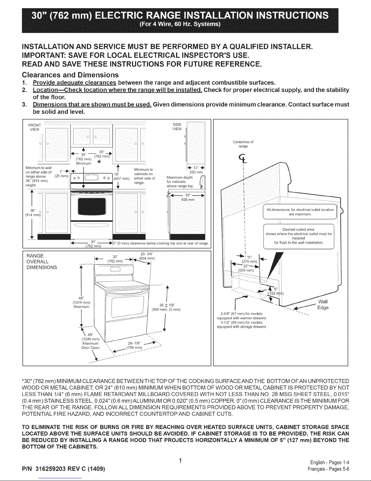
Clearances and Dimensions
1. Provide adequate clearances between the range and adjacent combustible surfaces.
2. LocationmCheck location where the ran_ will be installed. Check for proper electrical supply, and the stability
of the floor.
3. Dimensions that are shown must be used. Given dimensions provide minimum clearance. Contact surface must
be solid and level.
SIDE
VIEW
Centertine of
FRONT I__ ........ ............ ......
" (762r'nr'n) (7.6?2mm) _
Minimum to walt
on eitherside of 1"-1_
range above (25 mm)
36"(914 mm)
height.
Minimum
-- o o •
/
18" cabinets on
(457 ram) either side of
,_ range.
Minimum to
I'_--13" "_'I
for cabinets
Maximum depth
above range top.
330 mm
range
All dimensions for electrical outlet location
I 1
are maximum.
i
4---
,
RANGE _._ 30"
OVERALL (762 ram)
30" ,,
(762 mint "-_0 (O ram) clearance below cooking top and at rear of range.
shows where the electrical outlet must be
25_ 3/4"
(654 ram)
installed
Dashed cubed area
for flush to the wall installation.
DIMENSIONS ,, _iii_
48"
(1219 mm)
Maximum
T
36 ± 1/8"
(940 ram) (3 ram)
2_5/8" (67 mm) for models
equipped with warmer drawers
3_1/2" (89 ram) for models
equipped with storage drawers
Wall
Edge
*30" (762 mm) MINIMUM CLEARANCE BETWEEN THE TOP OF THE COOKING SURFACEAND THE BOTTOM OFAN UNPROTECTED
WOOD OR METAL CABINET; OR 24" (610 mm) MINIMUM WHEN BOTTOM OF WOOD OR METAL CABINET IS PROTECTED BY NOT
LESS THAN 1/4" (6 mm) FLAME RETARDANT MILLBOARD COVERED WITH NOT LESS THAN NO. 28 MSG SHEET STEEL, 0.015"
(0.4 mm) STAINLESS STEEL, 0.024" (0.6 mm)ALUMINUM OR 0.020" (0.5 mm) COPPER. 0" (0 mm) CLEARANCE IS THE MINIMUM FOR
THE REAR OF THE RANGE. FOLLOWALL DIMENSION REQUIREMENTS PROVIDED ABOVE TO PREVENT PROPERTY DAMAGE,
POTENTIAL FIRE HAZARD, AND INCORRECT COUNTERTOPAND CABINET CUTS.
TO ELIMINATE THE RISK OF BURNS OR FIRE BY REACHING OVER HEATED SURFACE UNITS, CABINET STORAGE SPACE
LOCATED ABOVE THE SURFACE UNITS SHOULD BE AVOIDED. IF CABINET STORAGE IS TO BE PROVIDED, THE RISK CAN
BE REDUCED BY INSTALLING A RANGE HOOD THAT PROJECTS HORIZONTALLY A MINIMUM OF 5" (127 turn) BEYOND THE
BOTTOM OF THE CABINETS.
PIN 316259203 REV C (1409} Fran_ais-Pages5-8
English- Pages1-4
iMPORTANT SAFETY
iNSTRUCTiONS
ifthe informationinthis manual isnotfollowed
exactly, afire or electrical shock may result causing property
damage, personal injury or death.
Before Starting
Tools You May Need
For leveling legs and Anti-Tip Bracket:
• Adjustable wrench or channel lock pliers
• 5/16" (21 mm) Nutdriver or Flat Head Screwdriver
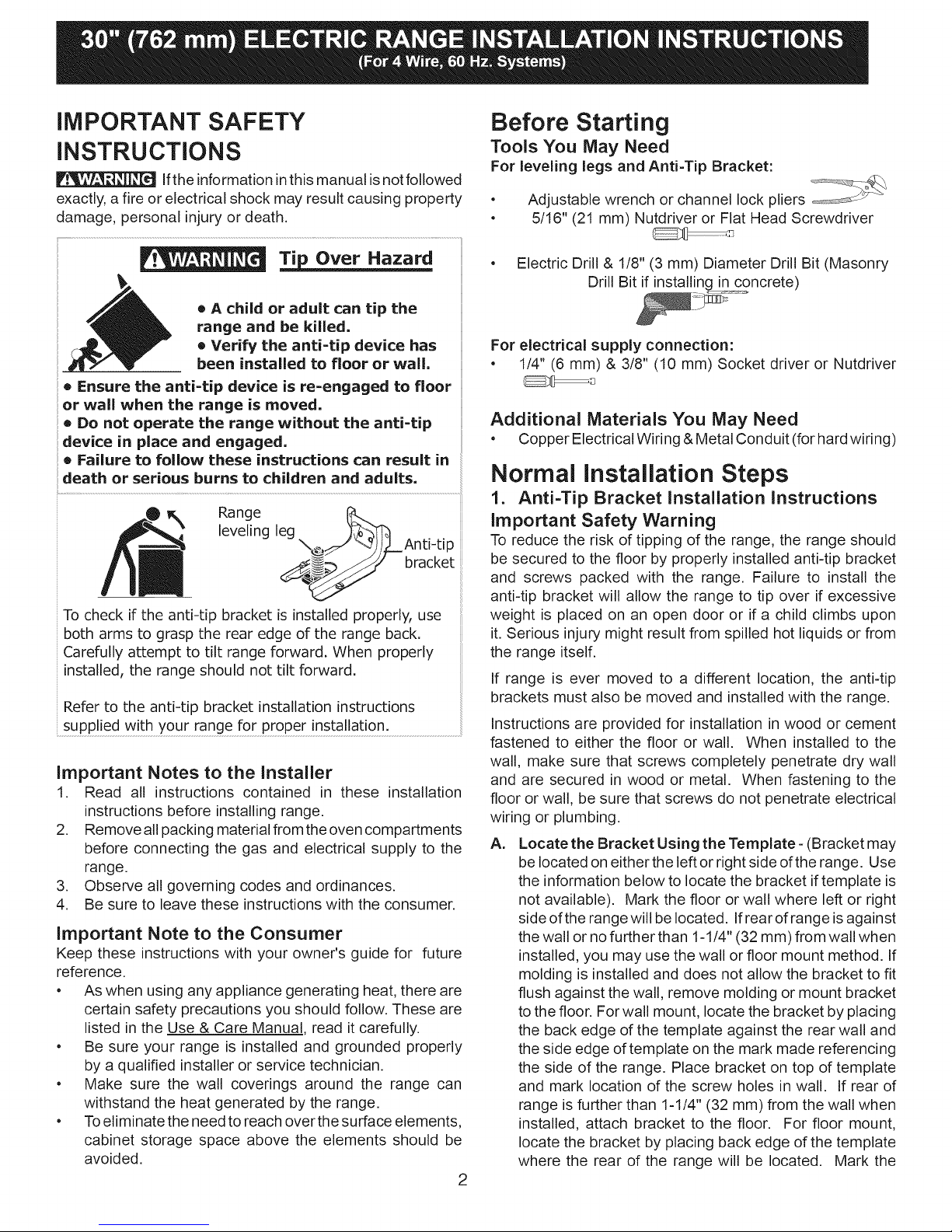
T_ Over Hazard
® A child or adult can tip the
range and be killed,
• Verify the anti-tip device has
been installed to floor or wall.
= Ensure the anti-tip device is re-engaged to floor
or wall when the range is moved.
= Do not operate the range without the anti-tip
device in place and engaged.
= Failure to follow these instructions can result in
death or serious burns to children and adults.
Range leg _:_]1"_
leveling \_ _)/_L_Anti-tip
_m_f bracket
To check if the anti-tip bracket is installed properly, use
both arms to grasp the rear edge of the range back.
Carefully attempt to tilt range forward. When properly
installed, the range should not tilt forward.
Refer to the anti-tip bracket installation instructions
supplied with your range for proper installation.
Important Notes to the Installer
1. Read all instructions contained in these installation
instructions before installing range.
2. Remove allpacking material from the oven compartments
before connecting the gas and electrical supply to the
range.
3. Observe all governing codes and ordinances.
4. Be sure to leave these instructions with the consumer.
important Note to the Consumer
Keep these instructions with your owner's guide for future
reference.
• As when using any appliance generating heat, there are
certain safety precautions you should follow. These are
listed in the Use & Care Manual, read it carefully.
• Be sure your range is installed and grounded properly
by a qualified installer or service technician.
• Make sure the wall coverings around the range can
withstand the heat generated by the range.
• Toeliminate the need to reach over the surface elements,
cabinet storage space above the elements should be
avoided.
• Electric Drill & 1/8" (3 mm) Diameter Drill Bit (Masonry
Drill Bit if installing in concrete)
For electrical supply connection:
• 1/4" (6 mm) & 3/8" (10 mm) Socket driver or Nutdriver
Additional Materials You May Need
• Copper Electrical Wiring &Metal Conduit (for hard wiring)
Normal installation Steps
1. Anti=Tip Bracket Installation instructions
important Safety Warning
To reduce the risk of tipping of the range, the range should
be secured to the floor by properly installed anti=tip bracket
and screws packed with the range. Failure to install the
anti=tip bracket will allow the range to tip over if excessive
weight is placed on an open door or if a child climbs upon
it. Serious injury might result from spilled hot liquids or from
the range itself.
If range is ever moved to a different location, the anti=tip
brackets must also be moved and installed with the range.
Instructions are provided for installation in wood or cement
fastened to either the floor or wall. When installed to the
wall, make sure that screws completely penetrate dry wall
and are secured in wood or metal. When fastening to the
floor or wall, be sure that screws do not penetrate electrical
wiring or plumbing.
A=
Locate the Bracket Using the Template- (Bracket may
be located on either the left or right side of the range. Use
the information below to locate the bracket if template is
not available). Mark the floor or wall where left or right
side of the range will be located. If rear of range is against
the wall or no further than 1-1/4" (32 mm) from wall when
installed, you may use the wall or floor mount method. If
molding is installed and does not allow the bracket to fit
flush against the wall, remove molding or mount bracket
to the floor. For wall mount, locate the bracket by placing
the back edge of the template against the rear wall and
the side edge of template on the mark made referencing
the side of the range. Place bracket on top of template
and mark location of the screw holes in wall. If rear of
range is further than 1-1/4" (32 mm) from the wall when
installed, attach bracket to the floor. For floor mount,
locate the bracket by placing back edge of the template
where the rear of the range will be located. Mark the
2
location of the screw holes, shown in template.
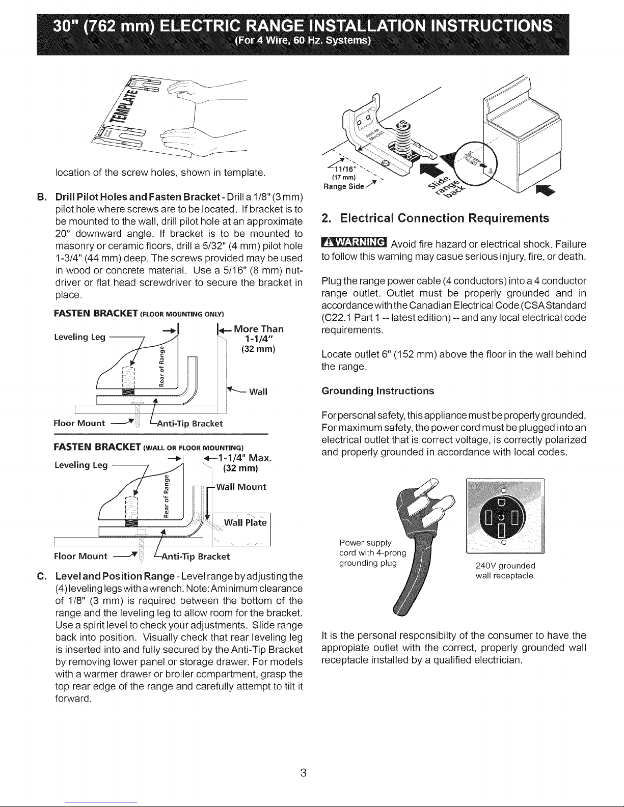
B=
Drill Pilot Holes and Fasten Bracket- Drill a 1/8" (3 mm)
pilot hole where screws are to be located. If bracket isto
be mounted to the wall, drill pilot hole at an approximate
20° downward angle. If bracket is to be mounted to
masonry or ceramic floors, drill a5/32" (4 mm) pilot hole
1-3/4" (44 mm) deep. The screws provided may be used
in wood or concrete material. Use a 5/16" (8 mm) nut-
driver or flat head screwdriver to secure the bracket in
place.
FASTEN BRACKET(FLOO_MOUNTINGONLY)
Leveling Leg --
More Than
_ 1=1/4"
(32 ram)
r :t "
Floor Mount LAnti=TipBracket
FASTEN BRACKET (WALL OR FLOOR MOUNTING)
-=_1 1_-=1=1/4'' Max.
LevelingLeg -- (32 mm)
(17 mm) _"
Range Side7 _
2. Electrical Connection Requirements
Avoid fire hazard or electrical shock. Failure
to follow this warning may casue serious injury, fire, or death.
Plug the range power cable (4 conductors) into a 4 conductor
range outlet. Outlet must be properly grounded and in
accordance with the Canadian Electrical Code (CSAStandard
(C22.1 Part I --latest edition) -- and any local electrical code
requirements.
Locate outlet 6" (152 mm) above the floor in the wall behind
the range.
Grounding Instructions
Forpersonal safety, this appliance must be properly grounded.
For maximum safety, the power cord must be plugged into an
electrical outlet that is correct voltage, is correctly polarized
and properly grounded in accordance with local codes.
Mount
FIoorMount p Bracket
C=
Level and Position Range - Level range by adjusting the
(4) leveling legswith awrench. Note:Aminimum clearance
of 1/8" (3 mm) is required between the bottom of the
range and the leveling leg to allow room for the bracket.
Use a spirit level to check your adjustments. Slide range
back into position. Visually check that rear leveling leg
is inserted into and fully secured by the Anti-Tip Bracket
by removing lower panel or storage drawer. For models
with a warmer drawer or broiler compartment, grasp the
top rear edge of the range and carefully attempt to tilt it
forward.
Power supply __
cord with 4-prong
grounding plug
240V grounded
wall receptacle
It is the personal responsibilty of the consumer to have the
appropiate outlet with the correct, properly grounded wall
receptacle installed by a qualified electrician.
3
 Loading...