

Page 1

AUTOMATIC ICE MAKER
INSTALLATION INSTRUCTIONS
IMPORTANT
We recommend an authorized service technician to install the ice maker kit.
WARNING
• To avoid electric shock, which can cause death or severe personal injury, disconnect the refrigerator
from electrical power before connecting a water supply line to the refrigerator.
• Connect the ice maker to a potable water supply only.
NOTE
Check with your local building authority for recommendations on water lines and associated materials prior
to installing your new refrigerator. For household water line hookup from the home water supply system to
the unit, we recommend for homes with existing valves Smart Choice® water line kit 5304437642 (with a 6�
Stainless Steel Water Line) and for homes without an existing valve, we recommend Smart Choice® water
line kit 5304493869 (with a 6� Polyline Waterline). Please refer to Frigidaire.com for more information.
Tools Needed:
• Flat head screw driver • Phillips or Quadrex driver
• ¼" Hex driver • Gloves
• Drill • Needle nose pliers
• Plastic putty knife
Ice Maker (IMKTF20A) Kit Components
Ice Maker
QTY: 1
Plastic Clamp
QTY: 3
Ice Container
QTY: 1
Ice Maker
Connector Cover
QTY: 1
Screw (A)
QTY: 2
Water Inlet Tube Assembly
QTY: 1
Screw (B)
QTY: 2
Water Valve
QTY: 1
P/N: A22932801
Page 2
Ice Maker Installation Instructions
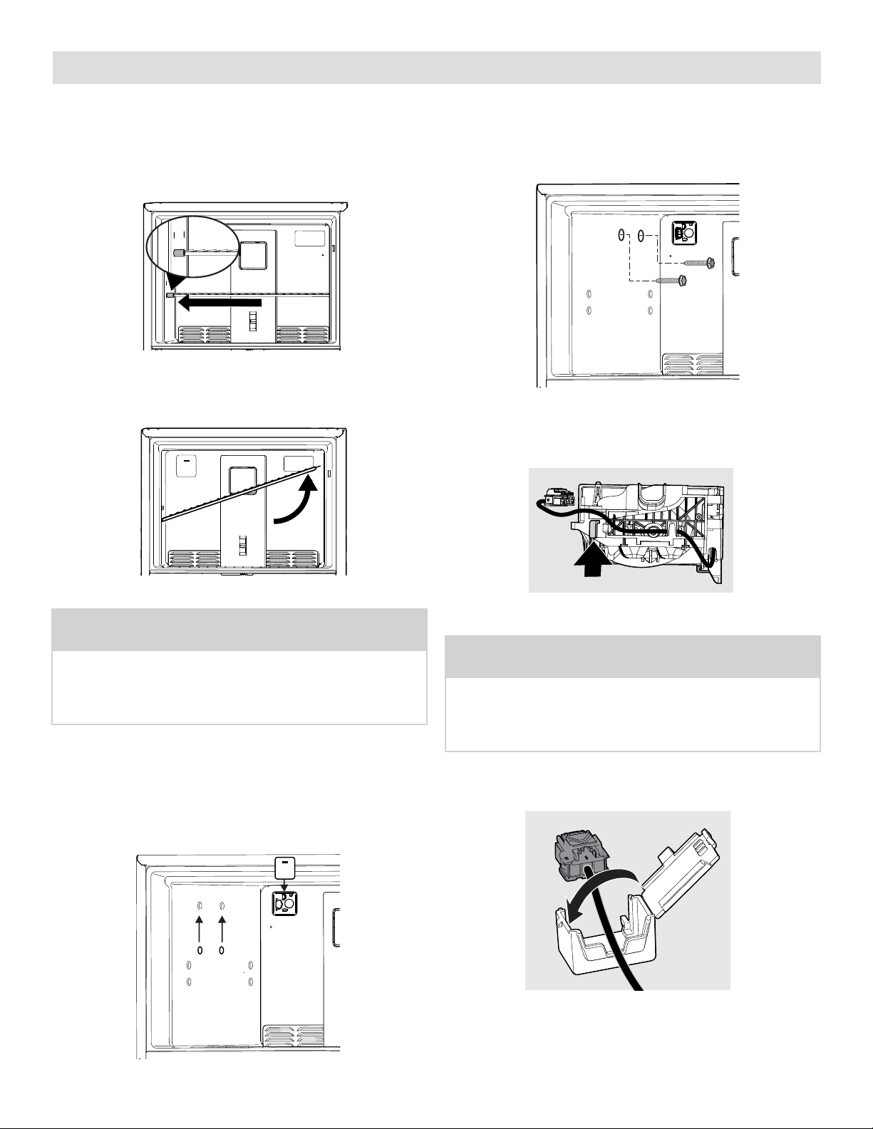
1. Unplug the refrigerator from the electrical outlet.
2. Remove the spacer. Remove the freezer shelf
(some models) by pushing the shelf to the left
until the right side of the shelf comes free from
the holes. See Figure 1.
Figure 1
Then slowly lift up and pull the shelf free from the
holes on the right side. See Figure 2.
5. Place two, long, ice maker mounting screws (A)
into freezer wall where plugs were removed
in Step 3. Turn each screw clockwise until ½"
remains out. See Figure 4.
A
Figure 4
6. Unhook one loop of the ice maker harness.
See Figure 5.
Figure 2
NOTE
Some models have two plugs on the left freezer wall
that must be removed. These holes will be used to
mount the Ice Maker. (You will also insert the Water
Inlet Tube in the plug on the back wall.)
3. Use a plastic putty knife to remove the 2 plugs on
the left wall of the freezer compartment. Discard
the plugs. See Figure 3.
4. Remove the harness connector cover, where the
ice maker will plug in, with a flathead screwdriver.
Discard the harness connector cover. See Figure 3.
Figure 5
NOTE
You will need both hands to hook up and secure
the Ice Maker to the freezer wall. DO NOT let the
Ice Maker dangle free after the wiring harness is
plugged into the connector on the back freezer wall.
7. Place the ice maker harness into the cover.
See Figure 6.
Figure 3
Figure 6
2
Page 3

Ice Maker Installation Instructions
8. Connect the ice maker connector into the mating
connector mounted on the back freezer panel.
See Figure 7.
Figure 7
9. Slide the ice maker connector cover over the
connector (hook on left A, snap on right B).
See Figure 8.
A
B
10. Slide the ice maker onto the back screw. See
Figure 9A. Then slide the ice maker down onto
the front screw. See Figure 9B.
Figure 9A
Figure 9B
11. Mount the ice maker to the side wall with the 2
screws (A). Tighten the screws to secure the ice
maker in place. See Figure 10.
A
A
A
Figure 10
12. Reinstall the freezer shelf in the lower position.
Place the ice container on the shelf. See Figure 11.
Figure 8
Figure 11
3
Page 4

Back of Cabinet Water Valve Installation Instructions
Remove and Discard Foam
CAUTION
Wear gloves and use extreme CAUTION when
handling the access cover.
13. Remove the 4 screws securing the access cover
to the cabinet. See Figure 12.
Figure 12
14. Cut the Ice Maker Installation label on dashed
lines located on the outside rear panel of the
refrigerator at the top, right corner. Push the flaps
inward until they stick to the unit. See Figure 13.
16. Push the water inlet tube through the small hole
where the Installation label is located. Start the
install with the tube at 45° (A). Fully insert the
tube, and then twist it clockwise to 90° (B) to
lock it in place. Pull lightly to make sure the tube
is secure. See Figure 15.
1
2
Cut on dashed lines
and push in on flaps
Figure 13
15. If necessary, remove any foam from within the
access hole with needle nose pliers. See Figure 14.
ICE MAKER
INSTALLATION
A
B
Figure 15
IMPORTANT
Make sure the water inlet tube is sitting inside the
fill cup. See Figure 16.
ICE MAKER
INSTALLATION
Figure 14
Figure 16
4
Page 5

Back of Cabinet Water Valve Installation Instructions
17. Plug the connector on the supplied water valve
into the harness found in the bottom right of the
compressor compartment. See Figure 17.
Figure 17
Install the supplied clip into the compartment and
route the water valve harness through clip.
See Figure 18.
18. Place the green water tube to the ice maker into
the bottom outlet of the water valve. Push the
tube into the valve up to the black line marked
on the tube. Lightly pull on the tube to make sure
you installed it correctly. See Figure 19.
Figure 19
19. The water valve location has pre-made holes on the
right rear of the unit. The water line should be oriented downward when the valve is installed. Install
the water valve using a ¼" hex head driver or drill,
install the 2 hex head screws (B). Tighten screws
until they are snug and then tighten an additional
¼" turn. See Figure 20.
Figure 18
NOTE
Connect the plastic water supply tubing and
the wiring harness to the water valve prior to
mounting the valve to the rear panel because
of space constraints.
B
Figure 20
5
Page 6

Back of Cabinet Water Valve Installation Instructions
NOTE
Clean the back of the cabinet with a commercial
household cleaner, ammonia or alcohol before
applying plastic clamps to the water tubing.
20. Secure the plastic water tubing to the rear of the
cabinet with two plastic clamps. See Figure 21.
21. Remount the access cover by hooking it on the
back bottom of the cabinet. Route the water tube
from the bottom to the outside, securing the
access cover with the 4 screws. See Figure 22.
Figure 22
Figure 21
6
Page 7
Connecting Ice Maker to Water Supply
WARNING
To avoid electric shock, which can cause death or
severe personal injury, disconnect the refrigerator
from electrical power before connecting a water
supply line to the refrigerator.
CAUTION
To Avoid Property Damage:
• Use stainless steel braided tubing for the water
supply line. Do not use water supply tubing made
of ¼" plastic. Plastic tubing greatly increases the
potential for water leaks, and the manufacturer
will not be responsible for any damage if you use
plastic tubing for the supply line.
• DO NOT install water supply tubing in areas
where temperatures fall below freezing.
• Chemicals from a malfunctioning softener
can damage the ice maker. If the ice maker is
connected to soft water, ensure the softener is
maintained and working properly.
IMPORTANT
Ensure your water supply line connections comply
with all local plumbing codes.
Before Installing the Water Supply Line, You Will Need:
• Basic Tools: adjustable wrench, flat-blade
screwdriver, and Phillips screwdriver
• Access to a household cold water line with water
pressure between 30 and 100 psi.
• A water supply line made of stainless steel tubing.
To determine the length of tubing needed, measure
the distance from the ice maker inlet valve at the
back of the refrigerator to your cold water pipe, so
the refrigerator can be moved out for cleaning.
• A shuto valve to connect the water supply line to
your household water system. DO NOT use a selfpiercing type shuto valve.
• Do not reuse compression fitting or use thread
seal tape.
NOTE
Check with your local building authority for
recommendations on water lines and associated
materials prior to installing your new refrigerator.
Depending on your local/state building codes,
we recommend for homes with existing valves
Smart Choice® water line kit 5304437642 (with a 6'
Stainless Steel Water Line) and for homes without an
existing valve, we recommend Smart Choice® water
line kit 5304493869 (with a 6’ Polyline Waterline).
Please refer to Frigidaire.com for more information.
To Connect the Water Supply Line To the Ice Maker
Inlet Valve
1. Disconnect the refrigerator from the electrical
power source.
2. Place the end of the water supply line into a sink
or bucket. Turn ON the water supply and flush the
supply line until the water is clear. Turn OFF the
water supply at the shuto valve.
3. Remove the plastic cap from the water valve inlet
and discard the cap.
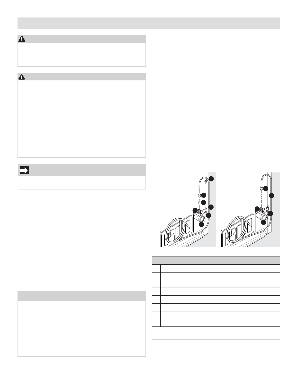
4. If you use copper tubing, slide the brass compression nut, and then the ferrule (sleeve) onto
the water supply line. Push the water supply line
into the water valve inlet as far as it will go (¼" /
6.4 mm). Slide the ferrule (sleeve) into the valve
inlet and finger tighten the compression nut onto
the valve. Tighten another ½ turn with a wrench;
DO NOT overtighten.
If you use braided flexible stainless steel tubing,
the nut is already assembled on the tubing. Slide
the nut onto the valve inlet and finger tighten
the nut onto valve. Tighten another ½ turn with a
wrench; DO NOT overtighten.
Units with
copper
tubing
B
C
G
F
H
A Clamp
B Brass compression nut
C Ferrule sleeve
D Copper line
E Braided flexible stainless steel water line
F Water valve bracket
G Water valve inlet
H Water valve
Include enough tubing in loop to allow moving the
refrigerator out for cleaning.
Units with
A
braided flexible
stainless steel
tubing
D
Parts
B
E
G
F
H
7
Page 8

Connecting Ice Maker to Water Supply
5. With the steel clamp and screw, secure the water
supply line (copper tubing only) to the rear panel
of refrigerator as shown.
6. Coil the excess water supply line (copper tubing
only), about 2½ turns, behind the refrigerator
as shown and arrange the coils so they do not
vibrate or wear against any other surface.
7. To turn the ice maker on, press the ice maker’s
On/O power switch so the LED is illuminated.
8. Turn ON the water supply at the shuto valve and
tighten any connections that leak.
9. Reconnect the refrigerator to the electrical
power source.
Ice Service
If your refrigerator has an automatic ice maker, minimal ice will be produced during the first 24 hours of
operation. Air in new plumbing lines may cause the
ice maker to cycle 2 or 3 times before making a full
tray of ice. With no usage, it will take approximately 1
to 2 days to fill the ice bin.
New plumbing connections may cause the first production of ice cubes to be discolored or have an odd
flavor. Discard ice made during the first 24 hours.
Turning Your Ice Maker On
After the plumbing connections have been
completed, the water supply valve must be opened.
Place the ice bin under the ice maker, pushing it as
far back as possible. Press the ice maker’s On/O
button. The button will illuminate in green when the
ice maker is On.
Turning Your Ice Maker O
To stop the ice maker, press the ice maker’s On/O
button. The ice maker also stops producing
ice automatically when the bin is full, and then it
resumes when the level in the bin drops.
IMPORTANT
To ensure proper function for your ice maker, hook
up water supply immediately or turn ice maker OFF.
If the ice maker is on and the water supply is not
connected, the water valve can make a loud chattering noise.
Ice Production: What To Expect
The ice maker will produce 1.5 to 2 lbs of ice every
24 hours depending on usage conditions.
Ice is produced at a rate of 10 cubes every 100 to
160 minutes.
8
Page 9

Ice Maker Tips
Remember that water quality determines your ice
quality. If the water source uses a water softener,
ensure that the softener is maintained and working
properly. Chemicals from a malfunctioning softener
can damage the ice maker.
CAUTION
Do Not place the ice container in your dishwasher.
• Wash ice container in warm water with mild
detergent. Rinse well and dry.
• Stop the ice maker when cleaning the freezer or
for short vacations.
• If the ice maker will be turned o for a long
period of time, turn the water supply valve to
the closed position.
9
 Loading...