

Page 1
Installation
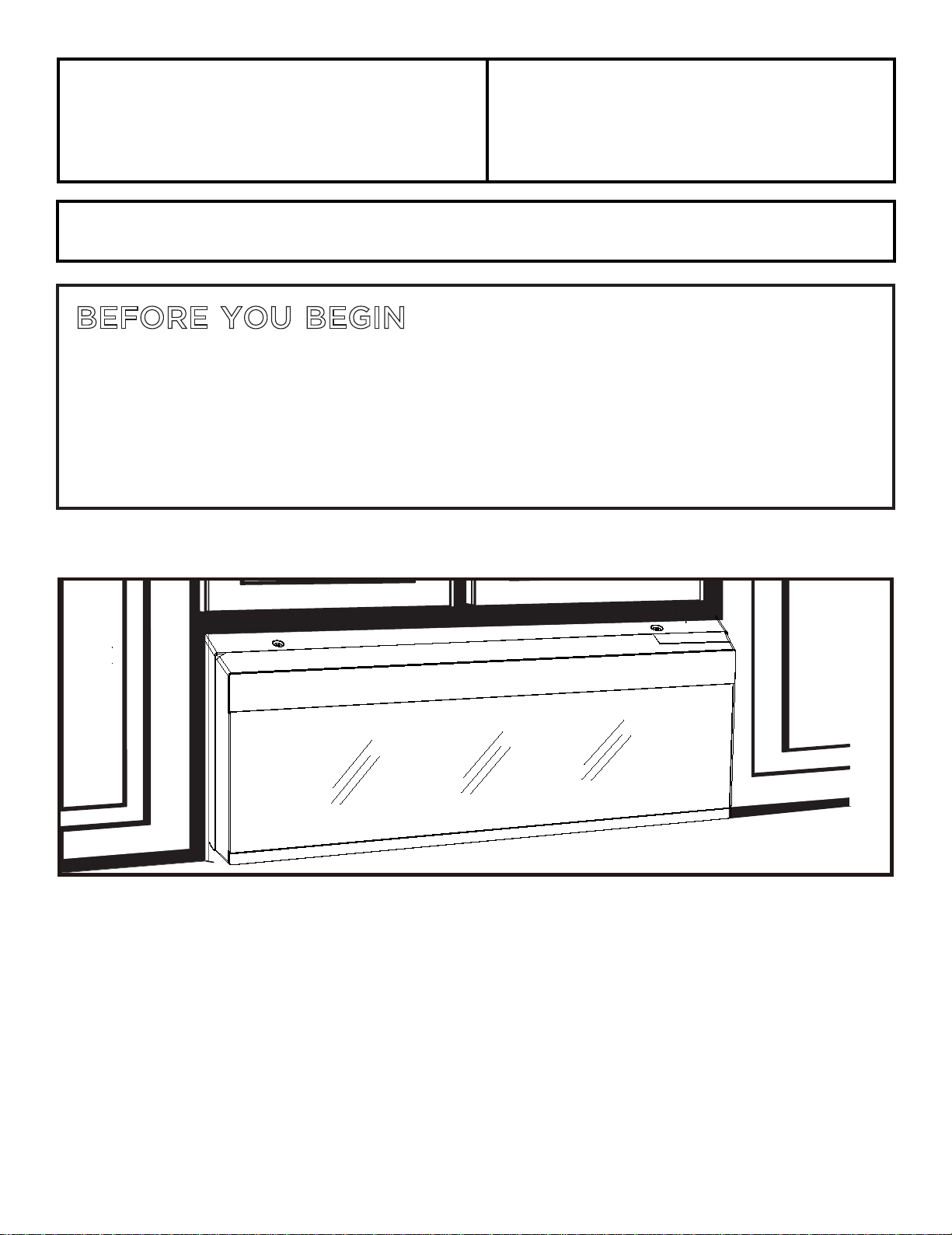
Over the Range
Instructions
Questions? Call 1-800-944-9044(US) or
BEFORE YOU BEGIN
Read these instructions completely and carefully.
• IMPORTANT-
local inspector's use.
• IMPORTANT- Observe all governing
codes and ordinances.
• Note to Installer - Be sure to leave these
instructions with the Consumer.
Save these instructions for
Microwave Oven
1-800-265-8352(Canada)
Note to Consumer - Keep these instructions
•
for future reference.
• Skill level - Installation of this appliance requires
basic mechanical and electrical skills.
• Proper installation is the responsibility of the
installer.
• Product failure due to improper installation is not
covered under the Warranty.
READ CAREFULLY.
KEEP THESE INSTRUCTIONS
p/n A06823451
August 2022
.
Page 2

Page 3
Installation Instructions
CONTENTS
General information
Important Safety Instructions .............................. 3
Electrical Requirements ....................................... 3
Damage – Shipment/Installation......................... 4
Parts Included........................................................... 4
Tools You Will Need ................................................ 5
Mounting Space ...................................................... 5
Step-by-step installation guide
Placement of The Mounting Plate ..................
Removing the Mounting Plate ................. 6
Finding the Wall Studs ...............................6
Determining Wall Plate Location .............7
Aligning the Wall Plate ............................ 8
Installation Types....................................................9
6–8
Outside Top Exhaust
C
................................19-22
Attach Mounting Plate to Wall.......19
Preparation of Top Cabinet............20
Adapting Microwave Blower for
Outside top Exhaust
Checking for Proper Damper
Operation...............................................21
Mount the Microwave Oven
Adjust the Exhaust Adaptor ...........22
Connecting Ductwork.......................22
Before You Use Your Microwave...........................23
.............. 20 -21
.....21-22
Recirculating .......................................... 10–12
A
Attach Mounting Plate to Wall .........
Preparation of Top Cabinet ...............
Check Blower Plate ............................
Mount the Microwave Oven .........11
Installing or Change
the Charcoal
External Exhaust Duct...................................... 13-14
Outside Back Exhaust...........................15–18
B
Preparing Rear Wall for
Outside Back Exhaust........................15
Remove Blower Plate.......................... 15
Attach Mounting Plate to Wall .......16
Preparation of Top Cabinet .............16
Adapting Microwave Blower
for Outside Back Exhaust............16–17
Mount the Microwave Oven ............18
Filter
...........................................12
10
11
11
–
12
EN-2
Page 4
Installation Instructions
IMPORTANT SAFETY INSTRUCTIONS
This product requires a three-prong grounded
outlet.
The installer must perform a ground continuity
check on the power outlet box before
beginning the installation to ensure that the
outlet box is properly grounded. If not
properly grounded, or if the outlet box does
not meet electrical requirements noted
(under ELECTRICAL REQUIREMENTS), a
qualified electrician should be employed to
correct any deficiencies.
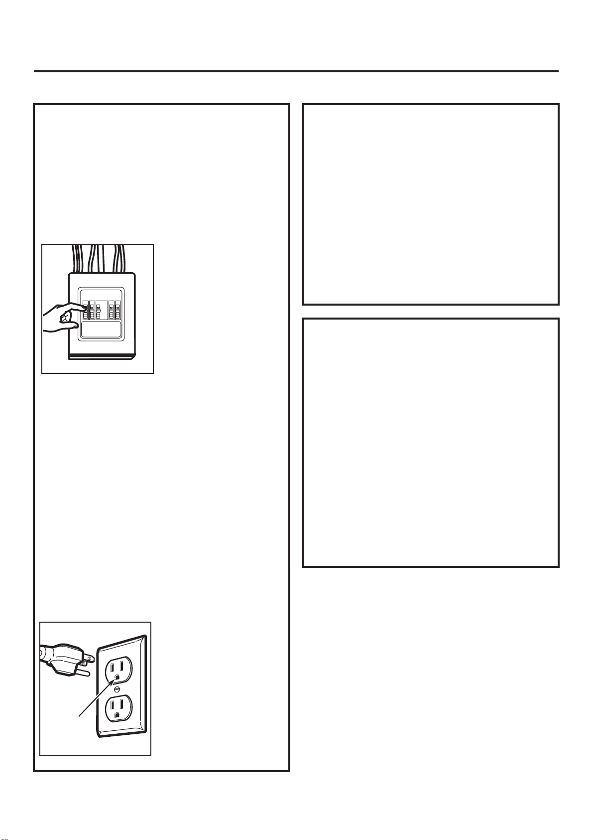
CAUTION: For
personal safety,
remove house fuse or
open circuit breaker
before beginning
installation to avoid
severe or fatal shock
injury.
You should have the wall receptacle and
circuit checked by a qualified electrician
to make sure the receptacle is properly
grounded.
Where a standard two-prong wall receptacle
is encountered, it is very important to have
it replaced with a properly grounded threeprong wall receptacle, installed by a qualified
electrician.
DO NOT, UNDER ANY CIRCUMSTANCES, CUT,
DEFORM OR REMOVE ANY OF THE PRONGS
FROM THE POWER CORD. DO NOT USE WITH
AN EXTENSION CORD.
ELECTRICAL
CAUTION: For personal safety, the mounting
surface must be capable of supporting the
cabinet load, in addition to the added weight
of this 63–85 pound
(28.5–38.5 kg) product, plus additional oven
loads of up to 50 pounds (22.7 kg) or a total
weight of
113–135 pounds (51.3–61.2 kg).
CAUTION: For personal safety, this product
cannot be installed in cabinet arrangements
such as an island or a peninsula. It must be
mounted to BOTH a top cabinet AND a wall.
NOTE: For easier installation and personal
safety, it is recommended that two people
install this product.
IMPORTANT – PLEASE READ CAREFULLY.
FOR PERSONAL SAFETY, THIS APPLIANCE
MUST BE PROPERLY GROUNDED TO AVOID
SEVERE OR FATAL SHOCK.
The power cord of this
appliance is equipped
with a three-prong
(grounding) plug
which mates with a
standard three-prong
(grounding) wall
Ensure proper
ground exists
before use
receptacle to minimize
the possibility of
electric shock hazard
from this appliance.
REQUIREMENTS
Product rating is 120 volts AC, 60 Hertz, 15
amps and 1.6 kilowatts. This product must be
connected to a seperate and dedicated supply
circuit of the proper voltage and frequency.
Wire size must conform to the requirements
of the National Electrical Code or the
prevailing local code for this kilowatt rating.
The power supply cord and plug should be
brought to a seperate and dedicated 15- to
20- ampere branch circuit single grounded
outlet. The outlet box should be located in the
cabinet above the microwave oven. The outler
box and supply circuit should be installed
by a qualifed electrician and conform to the
National Electrical Code or the prevailing local
code.
EN-3
Page 5
Installation Instructions
I
N
S
TA
L
L
AT
I
O
N
INS
T
RU
C
T
I
O
N
S
USE &
C
A
RE
M
A
NU
A
L
DAMAGE—SHIPMENT/
INSTALLATION
• If the unit is damaged in shipment, return
the unit to the store in which it was bought
for repair or replacement.
• If the unit is damaged by the customer,repair
or replacement is the responsibility of the
customer.
• If the unit is damaged by the installer
(if other than the customer), repair or
replacement must be made by arrangement
between customer
and installer.
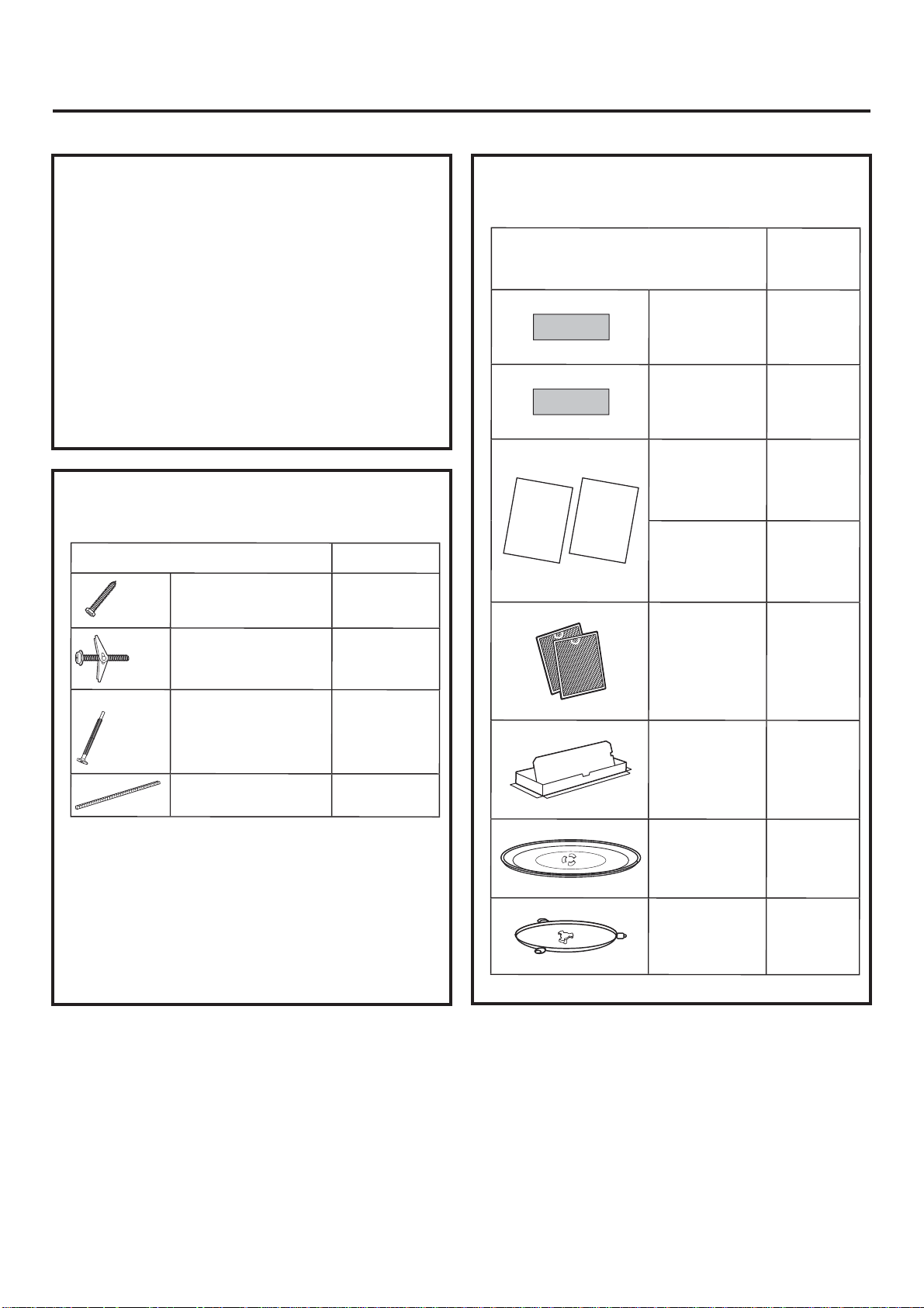
PARTS INCLUDED
HARDWARE PACKET
PART QUANTITY
Wood Screws
(1⁄4“ x 2“)
2
PARTS INCLUDED
(CONT.)
ADDITIONAL PARTS
PART QUANTITY
Top Cabinet
Template
Rear Wall
Template
Installation
Instructions
Use & Care
Manual
1
1
1
1
Toggle Bolts (and
wing nuts) (3⁄16“ x
2
3“)
Self-Aligning
Machine Screws
3
(1⁄4“-28 x 31⁄4“)
Nylon Grommet
(for metal cabinets)
1
You will find the installation hardware
contained in a packet with the unit. Check to
make sure you have all these parts.
NOTE: Some extra parts are included.
Separately
Packed
Grease Filters
Exhaust
adaptor
Glass Tray 1
Turntable
Ring
2
1
1
EN-4
Page 6
Installation Instructions
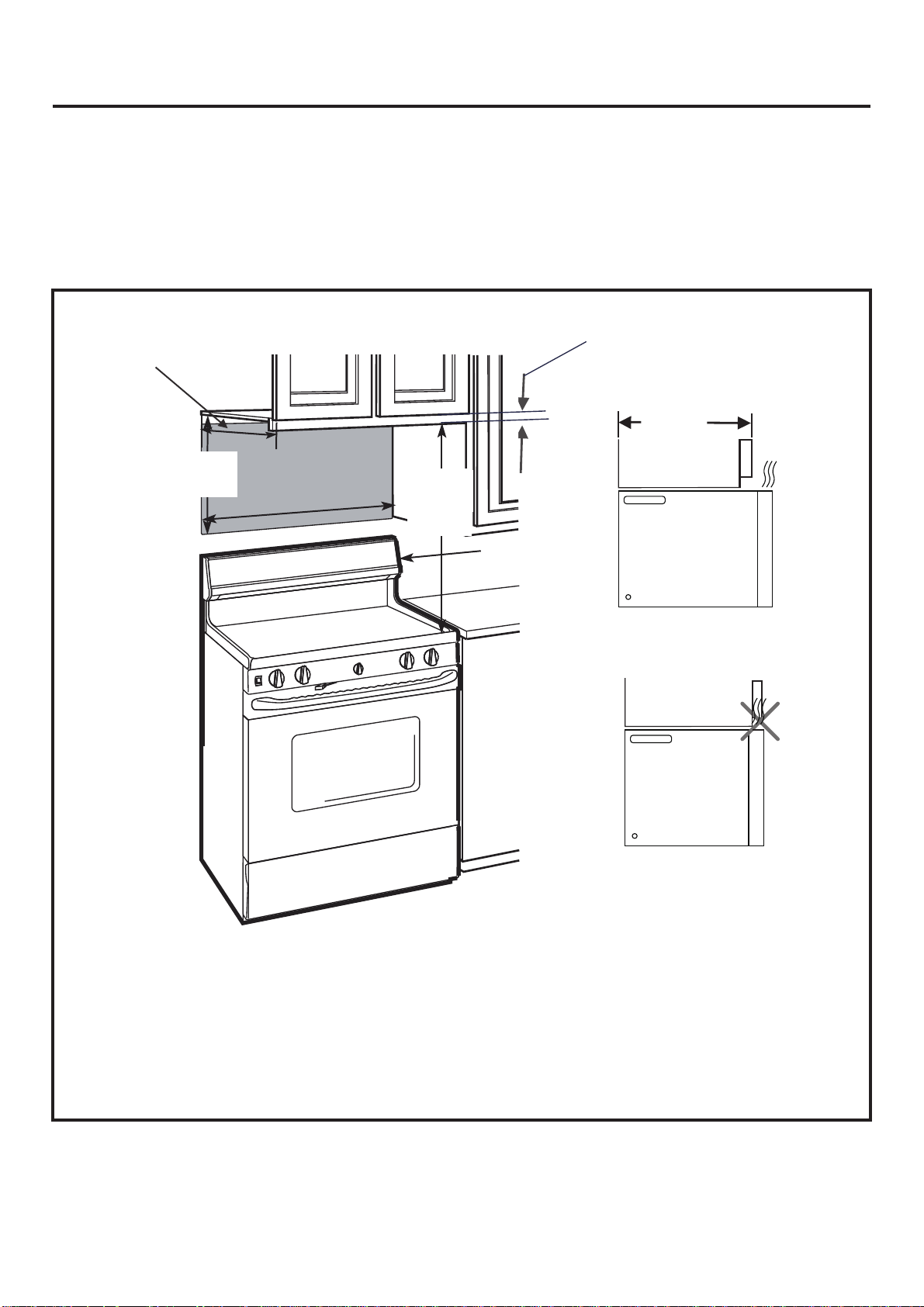
Tools you will need:
• Tape measure
• Hole saw
• Stud finder or hammer
• Level
• Duct and masking tape
• Scissors
13.8" Max
(35 cm)
10.3
"
(26.2cm)
Mounting Space
"
)
m
2c
.
6
7
0
"(
3
24
(61cm)
min.
•#1 Phillips screw driver
• Electric drill
•3/16”, 1/2”, 5/8” drill bit
• Filler wood blocks for recessed bottom
cabinets
• Tin snips
¼" Min
Clearance
13.8" MAX.
(35 cm)
Cabinet
Backsplash
Cabinet
• The space between the cabinets must be 30" (76.2 cm) wide and free of obstructions.
• If you are going to vent your microwave oven to the outside, see Hood Exhaust Section for
exhaust duct preparation
• When installing the microwave oven beneath smooth, flat cabinets, be careful to follow the
instructions on the top cabinet template for power cord clearance.
• As a guide to installation, see page 26 for Mounting Template Information.
• If the cabinet depth, including the cabinet doors, is more than 13.8”, then the unit must be spaced
out from wall using adequate materials supporting 150 lbs to allow proper top vent air exhaust/
intake.
EN-5
Page 7
Installation Instructions
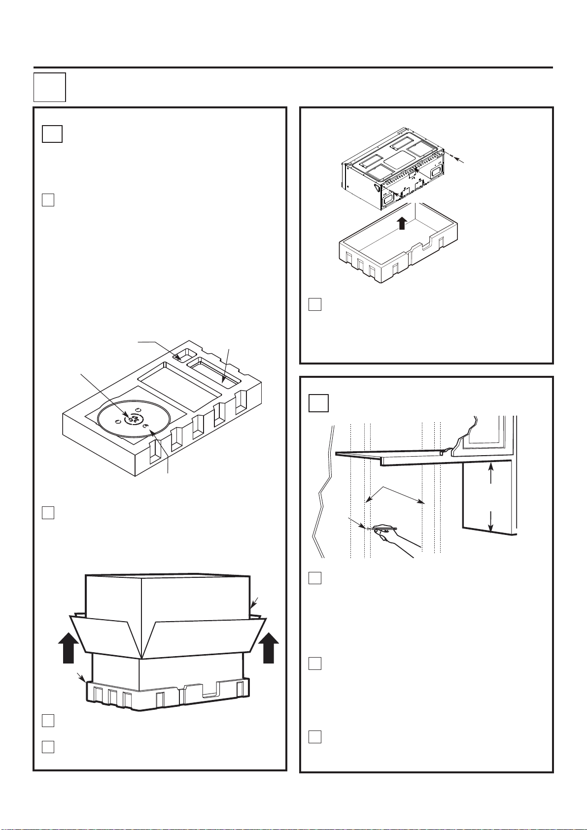
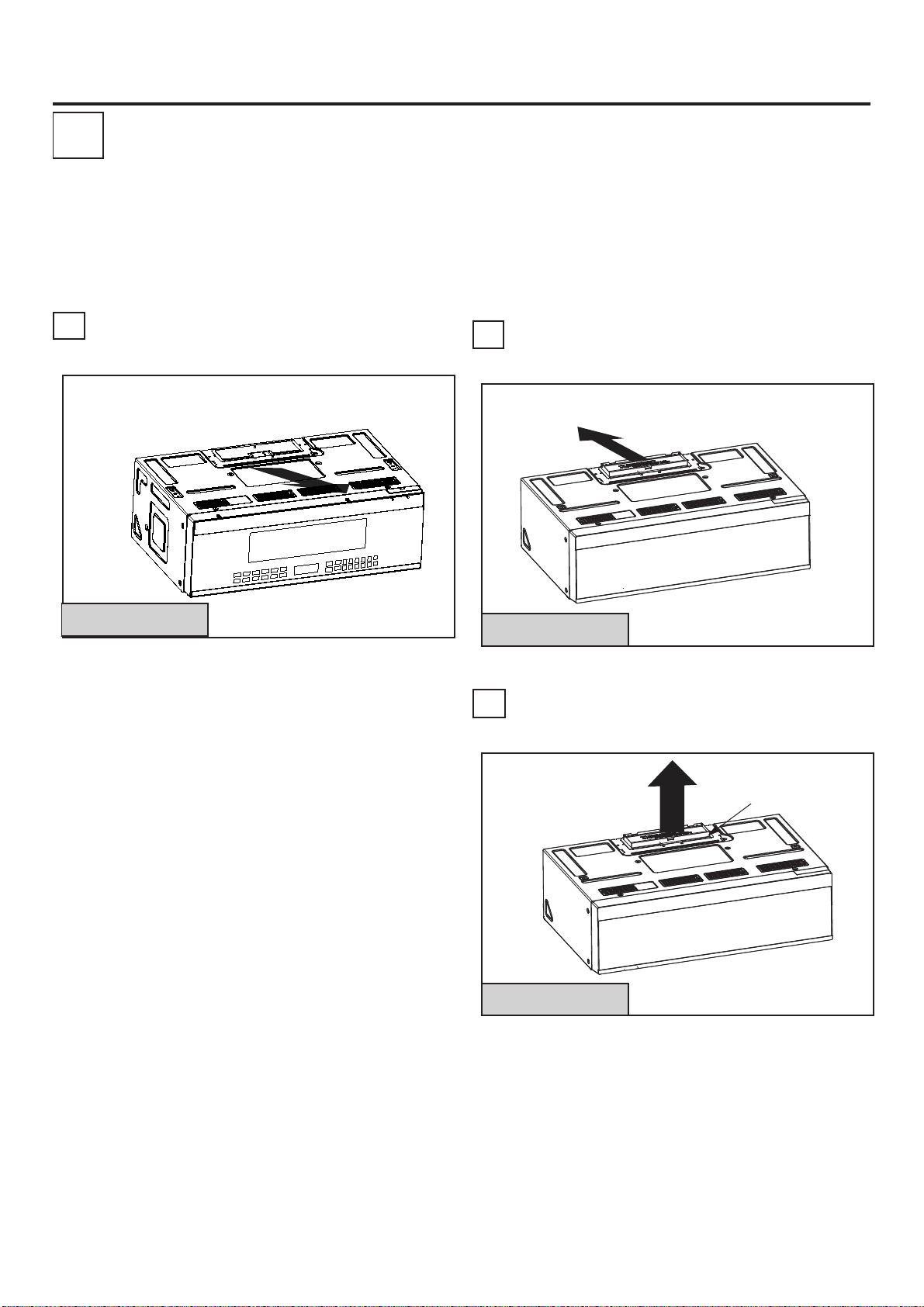
PLACEMENT OF THE MOUNTING PLATE
1
REMOVING THE MICROWAVE
A
.
OVEN FROM THE CARTON/
REMOVING THE MOUNTING
PLATE
Remove the installation instructions,use
1
and care, exhaust adapter, turntable ring,
filters, glass tray and the small hardware
bag. Do not remove the Styrofoam
protecting the top of the oven.
please note: Do Not Remove plastic plug
protective cover until just before hanging
the unit.
Keep the unit at least 8 inches away from
the counter top edge to preven to
dropping because of the heavy doo.r
Small Hardware Bag
Filters and Turntable
Ring below glass tray
Exhaust Adapter
Remove the screws from each end of the
5
mounting plate. This plate will be used as
the rear wall template and for mounting.
Reinstall the screws into the holes where
they were removed.
Screws
Screws
Mounting Plate
Glass Tray
Fold back all 4 carton flaps fully against
2
carton sides. Then carefully roll the oven
and carton over onto the top side. The oven
should be resting in the Styrofoam.
Styrofoam
Pull the carton up and off the oven.
3
Cut the middle of the outer protective
4
plastic bag to remove the mounting plate.
Carton
FINDING THE WALL STUDS
B.
Wall
Studs
10.3
"
(26.2cm)
Center
Find the studs, using one of the following
1
methods:
A. Stud finder – a magnetic device which
locates nails.
B. Use a hammer to tap lightly across the
mounting surface to find a solid sound.
This will indicate a stud location.
After locating the stud(s), find the center
2
by probing the wall with a small nail to find
the edges of the stud. Then place a mark
halfway between the edges. The center of
any adjacent studs should be 16 (40.6 cm)
or 24 (61 cm) from this mark.
Draw a line down the center of the studs.
3
THE MICROWAVE MUST BE CONNECTED TO
AT LEAST ONE WALL STUD.
EN-6
Page 8
3
/8
"
T
O
E
D
G
E
N
O
T
E
:
I
T
I
S
V
E
R
Y
I
M
P
O
R
T
A
N
T
T
O
RE
A
D
A
N
D
F
O
L
L
O
W
T
H
E
D
I
R
E
C
T
IO
N
S
I
N
T
H
E
I
N
S
T
A
L
L
A
T
I
O
N
I
N
S
T
R
U
C
T
I
O
N
S
B
E
F
O
R
E
P
R
O
CE
E
D
I
NG
W
I
T
H
T
H
I
S
R
E
A
R
W
A
L
L
T
E
M
P
L
A
T
E
.
Th
is
R
e
a
r
W
a
ll
Te
m
p
la
t
e s
er
v
e
s
to
p
os
it
i
o
n
the
b
o
t
to
m
mo
u
n
tin
g
p
la
t
e
a
n
d
t
o l
o
c
at
e
th
e ho
r
iz
o
n
ta
l e
x
h
a
us
t
ou
tle
t.
1
.
U
s
e
a
l
ev
el
to
c
he
ck
th
a
t
th
e
te
mp
la
t
e is
p
o
sit
i
o
n
e
d
a
c
c
u
r
a
t
e
ly
.
2
.
L
oc
a
te
an
d
m
a
r
k
a
t le
a
s
t
o
n
e s
t
u
d
o
n
t
he
le
ft
o
r
r
i
g
ht
s
id
e
o
f
th
e c
e
n
t
e
r
l
in
e.
It
is
i
mp
o
rta
n
t t
o
us
e a
t le
a
s
t
o
n
e
w
o
od
s
c
r
e
w
mo
un
t
ed
fir
mly
in
a
s
tu
d
t
o
s
u
pp
o
r
t
t
h
e
w
e
ig
h
t
o
f
th
e
mic
r
ow
a
v
e
.
Ma
r
k
t
w
o
a
dditio
nal,
e
v
e
nl
y
s
p
a
ce
d
lo
c
a
tio
n
s fo
r
t
h
e
s
upp
l
i
e
d t
og
g
le b
ol
ts
.
3.
D
r
i
l
l h
ole
s in
t
h
e ma
rke
d
lo
c
a
tio
n
s
.
W
h
e
re th
e
r
e
is
a
stu
d
, d
r
i
ll
a
3
/1
6
"
h
o
le
fo
r
w
o
od
s
c
r
e
w
s
.
Fo
r
h
o
le
s
t
h
a
t d
o n
o
t lin
e
u
p
w
ith
a s
t
ud
,
d
r
ill
5
/8
" h
o
les fo
r
to
g
g
le
bo
lts.
D
O
N
O
T INS
TA
L
L
T
H
E
MO
U
N
TIN
G
PL
ATE
AT
TH
I
S TI
M
E
.
4.
Re
m
ov
e
th
e
te
mpla
te
fr
om t
h
e
r
e
a
r
w
a
ll.
5
.
R
e
v
ie
w
t
he
In
s
t
a
l
l
atio
n
In
s
tru
c
t
io
n
bo
o
k fo
r
y
ou
r
in
sta
llatio
n
s
itu
a
tio
n.
L
o
c
a
t
e
a
n
d
m
a
r
k
h
o
l
e
s
to
a
l
i
g
n
w
i
t
h
h
o
l
e
s
i
n
t
h
e
m
o
u
n
t
i
ng
p
l
a
t
e.
IM
P
O
R
T
A
N
T
:
L
O
C
AT
E
A
T
L
E
A
S
T
O
N
E
S
T
U
D
O
N
E
I
T
H
E
R
S
I
D
E
O
F
T
H
E
C
E
N
T
E
RL
I
N
E
.
M
A
R
K
T
H
E
L
O
C
A
T
I
O
N
F
O
R
2
A
D
D
I
T
I
O
N
A
L
,
E
V
E
N
L
Y
S
P
A
C
E
D
T
O
G
G
L
E
B
O
L
T
S
I
N
T
H
E
M
O
U
N
T
I
N
G
P
L
A
T
E
A
R
E
A
.
L
o
c
a
t
e
a
n
d
m
a
r
k
h
o
l
e
s
t
o
a
l
i
gn
w
i
t
h
h
o
l
e
s
i
n
t
h
e
m
o
u
n
t
i
n
g
p
l
a
t
e
.
I
M
P
O
R
T
A
N
T
:
L
O
C
A
T
E
A
T
L
E
A
S
T
O
N
E
S
T
U
D
O
N
E
I
T
H
E
R
S
I
D
E
O
F
T
H
E
C
E
N
T
E
R
L
I
N
E
.
M
A
R
K
T
HE
L
O
CA
T
I
O
N
F
O
R
2
A
D
D
I
T
I
O
N
A
L
,
E
V
E
N
L
Y
S
P
A
C
E
D
T
O
G
G
L
E
B
O
L
T
S
I
N
T
H
E
M
O
U
N
A
R
E
A
.
T
r
i
m
t
h
e
r
ea
r
w
a
l
l
t
e
m
p
l
a
t
e
a
l
o
n
g
t
h
e
do
t
t
e
d
l
i
n
e
.
T
r
i
m
t
h
e
r
e
a
r
w
a
l
l
t
e
m
p
l
a
t
e
a
l
o
n
g
t
h
e
d
o
t
t
e
d
l
i
n
e
.
12
"
4
"
D
a
r
l
e
v
u
e
l
t
a
a
l
a
h
o
j
a
p
a
r
a
co
n
s
u
l
t
a
r
l
a
v
e
r
s
i
n
e
n
E
s
p
a
æ
o
l
.
Installation Instructions
C.
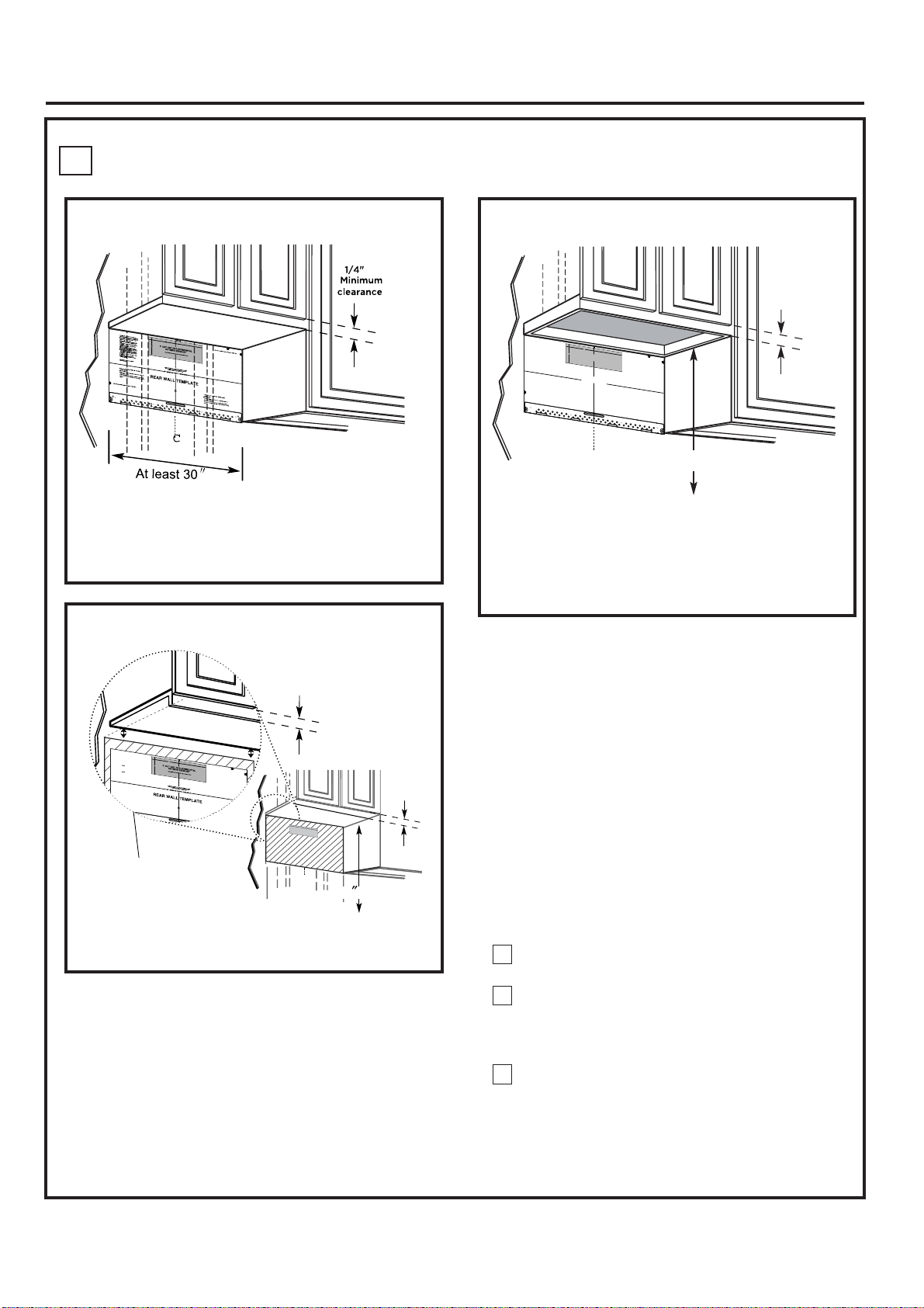
DETERMINING WALL PLATE LOCATION UNDER YOUR CABINET
Plate position-beneath fiat bottom
cabinet
Draw a vertical line on the wall at the
center of the 30" wide space.
Tape the Rear Wall Template onto the wall
matching the centerline and touching the
bottom of the cabinet.
Plate position-beneath recessed bottom
cabinet with front
1/4"
Minimum
clearance
1/4"
overhang
Minimum
clearance
Plate position-beneath framled recessed
cabinet
1/4"
Minimum
clearance
N
O
T
E
:
I
T
IS
V
E
R
R
E
Y
A
D
I
MP
A
N
O
D
R
F
T
O
A
I
N
N
L
L
T
THE
O
T
W
O
T
I
N
H
ST
E
DI
A
L
BE
R
L
E
A
F
CT
TI
OR
ON
I
O
E
NS
I
P
N
R
S
O
T
R
C
RU
E
EE
A
C
R
D
T
I
I
W
N
O
G
A
N
L
S
W
L
I
T
T
E
H
T
H
I
S
i
o
n
t
h
e
b
o
t
t
o
m
t
a
l
e
xh
a
u
s
t
i
s
p
o
s
i
t
i
o
n
e
d
t
h
e
l
e
f
t
o
r
e
w
o
o
d
t
t
h
e
w
e
i
gh
t
v
e
n
l
y
s
p
a
ced
e
r
e
t
h
e
re
i
s
w
s.
F
o
r
h
o
l
e
s
"
h
o
l
e
s
f
o
r
T
I
N
G
P
L
A
T
E
l
l
.
k
f
o
r
yo
u
r
la
n
w
i
t
h
h
o
l
e
s
i
n
t
h
e
UD
ON
E
I
T
H
E
R
S
I
D
E
O
F
2
A
D
D
I
T
IO
NA
L
,
E
V
4'#49#..6'/2.#6'
T
E
H
NL
E
M
Y
O
UN
T
I
N
G
P
L
A
T
E
d
l
i
n
e
.
&
3
/
8
"
T
O
E
D
G
E
12"
4
"
(%7
6176(14*
1765+&
14+
T
ri
m
<10
t
h
e
r
''
%
7
6*
1.
'
6*
4
1
7
)
*
4
'
#
4
%
#
7
6
+
10
Ä
+(
'
:
*
4
#
'
7
%
5
1
6
/
#
/
&
'
#
0
&
'
&
&
+
/
'
&
0
+5
5
+
%
1
*
#
4
)
'
+
0
61
/
+0+
/
7
/
9+&6*
%
ea
r w
6#
a
l
l
:*#756
9
#
.
.
2
6
14
+
5
0
)
4
'#
*
1
7
5
'
te
m
.
p
l
a
t
e
a
l
on
g
t
h
e
do
tt
e
d
l
i
n
e
.
(
1
4
'
:
*
#7
5
6
#
&
#
2
6
14
2
1
5
+
6
+
1
0
'
&
1
7
5
6
'
5
Ä
+
.
&
#
'
&
'
0
#
+
5
4
6
9
4
7
+.
%
.
6
7
4
'
4'
37
+
4'&
L
oc
a
t
e
a
nd
m
a
r
k
h
m
o
o
l
e
u
s
n
t
t
i
o
n
g
a
l
p
i
g
l
a
n
t
e
w
.
i
t
h
IM
ho
P
l
e
O
s
R
i
n
T
A
t
h
N
e
T
:
L
O
CA
T
E
A
T
L
E
AS
T
T
H
E
ON
C
E
E
NT
S
T
E
UD ON
R
L
I
N
MA
E
.
E
RK
I
TH
E
T
H
R
E
S
L
I
D
O
E
C
O
A
S
T
F
P
I
ON
A
C
E
F
D
O
T
R
O
2
G
A
G
DD
LE
A
I
R
T
B
E
I
O
O
A
N
L
.
T
A
S
L
,
I
N
E
V
THE
E
N
L
MO
Y
U
N
T
I
N
G
P
L
A
T
E
%
#
T
MP
h
i
s
R
L
e
A
a
TE
r
Wa
.
l
l
T
m
e
o
mp
u
n
l
t
a
i
n
t
e
g
s
p
e
l
a
r
v
t
e
e
s
a
o
n
t
u
o
d
t
l
p
e
t
o
o
t
.
si
l
o
t
c
a
t
e
t
h
e
1
h
.
o
Use
r
i
z
o
n
a
l
e
v
e
l
t
o
c
h
a
e
c
ck
c
u
t
r
h
a
a
t
e
t
l
t
y
h
.
e
t
e
2
m
.
L
p
o
l
a
c
t
a
e
t
e
a
n
d
m
a
r
k
r
i
g
a
h
t
t
l
e
s
a
i
d
st
e
o
o
n
f
e
t
h
s
e
t
u
01
c
d
e
n
o
t
n
6
e
r
'
l
i
n
e
I
.
t
is
i
m
p
o
sc
r
t
r
a
e
n
w
t
t
m
o
o
u
u
s
n
e
t
e
a
d
t
l
e
f
o
i
r
a
f
ml
s
t
h
t
y
e
o
i
n
m
n
i
a
cr
s
o
t
w
u
d
a
v
t
o
e
l
o
.
s
ca
M
u
p
t
a
i
o
p
r
k
o
n
s
r
t
w
f
o
o
r
a
t
d
h
d
e
i
3
t
su
i
.
o
Dr
n
pp
a
i
l
l
l
,
i
l
e
e
h
d
o
t
l
e
o
s
g
g
i
n
l
e
t
h
b
e
o
a
l
m
t
s
s
.
a
t
u
r
ke
d
,
d
d
r
l
o
i
l
l
c
a
a
t
3
i
o
/
1
n
t
6
s.
h
"
a
Wh
t
h
d
o
o
l
e
n
f
o
o
r
t
l
w
i
n
o
e
o
u
d
t
o
p
scr
g
w
g
i
l
e
t
e
h
b
a
o
s
l
t
t
s
u
.
d
,
d
r
01
i
l
l
5
/
6
8
'
D
O
N
O
T
A
I
T
N
T
S
H
T
A
I
S
L
L
T
I
T
M
H
E
E
.
4
M
.
O
R
U
e
N
m
o
v
e
t
h
e
t
e
5
m
.
R
p
e
l
a
v
t
i
e
e
w
f
r
o
t
h
m
e
t
h
I
n
e
st
r
a
e
i
n
l
a
l
a
s
r
ta
t
i
w
o
l
a
l
n
a
t
I
i
n
o
st
n
r
s
u
i
c
t
u
t
i
a
o
t
n
i
o
b
n
o
.
o
D
a
rl
e
v
u
e
l
t
a
a
la
v
e
h
r
s
o
i
j
ó
a
n
p
e
a
n
r
a
E
c
s
o
p
n
a
s
ñ
u
o
l
l
t
.
a
bottom
r
L
oc
a
t
e
a
n
d
ma
r
k
h
mo
o
l
e
u
s
n
t
t
i
o
n
g
a
l
p
i
g
l
a
te
.
I
MP
O
R
T
A
N
T
:
L
O
C
A
T
E
A
T
L
E
A
S
T
T
H
E
O
NE
C
E
N
S
T
T
E
R
L
I
N
MA
E
.
R
K
T
HE
L
O
C
A
S
T
P
I
O
A
CE
N
F
D
O
T
R
O
G
G
LE
A
R
B
E
OLT
A
.
S
I
N
T
r
i
m
t
h
e
re
a
r
w
a
l
l
temp
l
a
t
e
a
l
o
n
g
t
h
e
d
o
t
t
e
$
C
24" to Cooktop
Draw a vertical line on the wall at the
center of the 30" space.
Tape the Rear Wall Template onto the wall
matching the centerline and touching the
bottom cabinet frame.
Your cabinets may have decorative
trim that interferes with the microwave
installation. Remove the decorative trim
to install the microwave properly and to
make it level.
THE MICROWAVE MUST BE LEVEL.
N
OT
E
:
I
T
I
S
V
R
E
E
R
A
Y
D
I
M
A
P
N
O
D
R
F
T
O
IN
A
L
N
L
T
T T
O
H
E
W
I
O
N
T
H
S
E
T
A
D
B
L
I
E
L
R
F
A
E
O
T
C
R
I
O
T
E
I
N
O
P
N
I
R
N
S
ST
O
R
C
E
R
E
A
U
E
R
C
D
W
T
I
N
I
A
O
G
L
N
L
W
S
T
I
T
E
T
H
h
M
i
s
P
T
R
H
L
e
a
A
I
r
S
T
W
3
E
/
a
8
"
l
.
l
m
TO
T
e
o
m
u
E
n
D
p
ti
G
l
a
n
E
t
g
e
p
se
l
a
r
t
e
v
e
o
a
s
u
n
t
t
d
l
o
e
t
t.
p
o
o
lo
s
1
i
c
t
2"
i
a
o
t
n
e
t
t
h
h
1.
e
e
b
Us
h
o
o
t
r
e
t
o
i
z
a
m
o
n
l
e
t
a
v
e
l
e
l
x
t
o
h
a
c
a
h
u
c
e
Draw a line on
theback wall equal
to the depth of the
frontoverhang.
s
c
t
c
u
k
r
t
a
h
t
e
a
l
t
y
t
.
h
e
2
t
.
e
L
m
o
pl
c
a
a
t
t
e
e
a
i
n
s
d
p
o
m
s
ar
i
t
i
r
k
o
i
g
n
a
h
e
t
t
d
l
s
e
i
a
d
s
e
t
o
o
f
n
t
e
h
e
s
c
t
u
e
d
n
o
t
e
n
r
l
t
i
h
n
I
e
e
4
t
.
"
i
l
s
e
f
i
t
m
o
p
r
s
o
c
r
r
t
e
a
w
nt
m
t
o
o
u
u
n
s
e
t
e
a
d
o
t
f
f
l
i
e
r
th
m
a
e
s
l
y
t
mi
o
i
n
n
c
a
e
r
o
s
w
w
tu
oo
a
d
v
l
d
o
e.
t
o
c
a
M
s
t
u
i
ar
o
p
n
p
k
s
o
t
f
w
r
o
t
o
r
t
h
t
a
h
e
d
e
3
w
d
.
s
i
e
ti
u
D
i
o
p
g
r
n
i
h
p
l
a
l
t
l
i
h
l
e
,
o
d
e
l
v
e
t
o
e
s
g
n
i
g
n
l
y
l
e
t
s
h
pa
b
e
a
ol
m
s
c
t
t
e
s
a
u
.
d
r
d
k
,
e
d
r
i
l
l
a
3
/
t
1
h
at
d
o
n
o
t
li
ne
t
u
o
g
g
l
e
b
o
l
t
s
.
D
O
N
OT
A
T
I
N
T
H
I
S
T
I
M
E
.
4
.
R
e
m
o
v
e
t
h
e
t
5
e
.
m
R
e
v
i
e
w
t
h
e
I
n
s
ta
i
n
s
t
a
l
l
a
t
i
o
n
s
i
t
u
a
t
D
a
r
le
v
ue
l
t
a
a
v
l
a
e
r
h
s
i
n
e
n
E
s
p
a
æ
L
o
c
a
t
e
a
n
d
m
ar
m
o
u
n
t
i
n
g
p
l
a
t
e
I
M
P
O
R
T
A
NT
:
L
O
C
A
T
E
A
T
L
T
H
E
C
E
N
T
E
R
M
A
R
K
T
H
E
L
O
S
P
A
C
E
D
T
O
G
A
R
E
A
.
T
r
i
m
t
h
e
r
e
a
r
w
a
l
l
t
e
m
p
l
a
t
e
Tr
d
l
i
o
m
c
a
t
t
i
o
h
n
6
"
h
o
l
e
f
o
r
p
w
i
t
h
a
s
t
u
S
TA
L
L
T
H
p
l
a
te
f
r
o
m
t
l
l
a
t
i
o
n
I
n
s
t
r
i
o
n
.
o
j
a
p
a
r
a
c
o
l
.
k
h
o
l
e
s
.
E
A
S
T
O
L
I
N
E
.
C
A
T
I
O
G
L
E
B
O
a
l
o
n
g
t
h
e
s
.
W
r
e
h
a
e
re
r
w
t
w
h
o
e
o
d
s
c
r
e
w
s
.
d
,
dr
i
l
l
5
/
8
"
h
o
E
M
O
U
N
T
I
N
h
e
r
e
a
r
w
a
l
l
.
u
c
t
i
o
n
b
o
o
k
f
o
o
n
s
u
l
t
a
r
l
a
t
o
a
l
i
g
n
w
N
E
S
T
U
D
N
F
O
R
2
L
T
S
I
N
T
e
d
o
t
t
e
d
a
r
l
e
l
i
s
t
e
mp
F
o
r
h
l
e
s
f
o
G P
L
AT
r
y
o
u
r
it
h
O
N
A
D
D
H
E
l
i
n
e
l
a
t
e
o
l
e
s
r
E
h
o
l
e
s
i
n
E
I
T
H
E
I
T
I
O
N
A
M
O
U
N
.
a
l
o
n
g
t
h
e
d
o
t
t
e
d
l
i
n
e
t
h
e
R
S
I
D
E
O
F
L
,
E
V
E
N
L
Y
T
I
N
G
P
L
A
T
E
.
L
o
c
at
e
a
n
d
m
a
r
k
m
h
o
o
un
l
e
s
t
i
n
t
o
g
a
p
li
l
a
g
t
n
e
.
w
i
IM
th h
P
O
o
l
R
es
T
i
A
n
N
t
T
h
e
:
LO
C
A
T
E
A
T
L
E
A
T
ST
H
E
O
C
N
E
E
N
S
T
E
T
U
R
D
L
I
ON
N
M
E
A
.
R
E
K
I
T
T
H
H
E
E
R
L
S
O
I
D
C
S
E
A
P
TI
OF
AC
O
N
E
D
F
O
T
R
O
G
2
G
A
A
L
D
E
R
D
E
I
B
T
A
O
I
O
.
L
T
N
S
A
L
IN
,
E
T
V
H
E
E
N
M
L
Y
O
U
N
T
I
N
G
P
L
AT
E
C
to Cooktop
24
Use a level to make sure the cabinet bottom is
level.
If the cabinets have a front overhang only, with
no back or side frame, install the mounting plate
down the same distance as the front overhang
depth. This will keep the microwave level.
Measure the inside depth of the front
1
overhang.
Draw a horizontal line on the back wall
2
an equal distance below the cabinet
bottom as the inside depth of the front
overhang.
For this type of installation with front
3
overhang only, align the mounting tabs
with this horizontal line, not touching the
cabinet bottom as described in Step D.
EN-7
Page 9
Installation Instructions
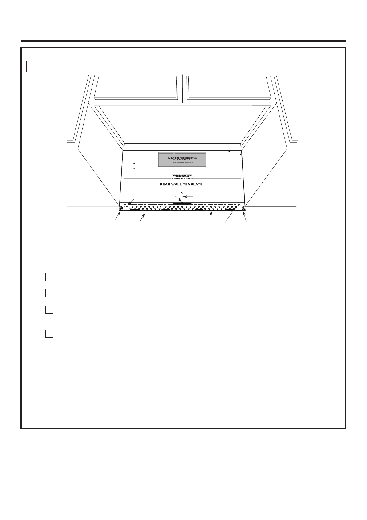
D.
ALIGNING THE WALL PLATE
NOTE: IT IS VERY IMPORTANT TO
READ AND FOLLOW THE DI
IN THE INSTALLATION INSTRUCTIONS
BEFORE PROCEEDI
REAR WALL TEMPLATE.
This Rear Wall Template serves t
mounting plate and to locate the horizontal exhaust
outlet.
1. Use a level to check th
accurately.
2. Locate and ma
right side of the centerlin
It is important to use at least one wood
screw mounted firmly in a stud to s
of the microwave. Mark two add
locations for the supp
3. Drill holes in the marked locatio
a stud, drill a 3/16" hole for
that do not line up with a st
toggle bolts.
DO NOT INSTALL THE M
AT THIS TIME.
4. Remove the template from the rear wall.
5. Review the Installation Instru
installation situation.
Darle vuelta a la hoja para consultar la
versión en Español.
Locate and mark
mounting plat
IMPORTANT:
LOCATE
AT LEAST ONE
THE CENTERLINE.
MARK THE LOCATION FOR 2
SPACED
TOGGLE BOLTS IN
AREA.
HoleB
NG WITH
at the template is positioned
rk at least one stud on the left or
e.
lied toggle bolts.
wood screws. For hole
ud, drill 5/8" holes for
holes to align with h
e.
RECTIONS
THIS
o position the bottom
upport the weight
itional, evenly spaced
ns. Where there is
OUNTING PLATE
ction book for your
STUD ON EITHER SIDE OF
ADDITIONAL, EVENLY
THE MOUNTING PLATE
s
oles in the
4"
Centerline
notches
3/8" TO EDGE
12"
Draw a Vertical Lineon
Wall from Centerof Top
Cabinet
Trim the rear
Locate and mark
mounting plat
e.
IMPORTANT:
LOCATE
AT LEAST ONE
THE CENTERLINE.
MARK THE LOCATION FOR 2
SPACED
TOGGLE BOLTS IN
AREA.
holes to align with hol
wall template al
STUD ON EITHER SIDE OF
ADDITIONAL, EVENLY
THE MOUNTING PLATE
ong the dotted
line.
es in the
Horizontal Line
Draw a vertical line on the wall at the
1
Area E
center of the 30" wide space.
Draw a horizontal line on the wall at
2
the bottom of “Rear Wall Template”.
Find a wall stud in area "E" of
3
mounting plate Refer to section 1B.
Finding the wall studs.
For attaching the mounting plate
4
into stud drill a 3/16" hole into wood
stud. Drill a 5/8" hole for toggle bolt
in 1 other location (Hole A or Hole B)
NOTE: DO NOT MOUNT THE PLATE
AT THIS TIME.
Hole A
C
Draw a horizontal line on wall at the
L
bottom of “Rear Wall Template”.
Horizontal Line
NOTE: Holes A and B are inside area E. If
neither of Holes A and B are not in a stud, find
a stud somewhere in area E and draw a circle
to line up with the stud. It is important to have
at least one wood screw mounted firmly in a
stud to support the weight of the microwave.
Set the mounting plate aside.
EN-8
Page 10
Installation Instructions
2
IMPORTANT SAFETY INSTRUCTIONS
Thi s microwave oven is designed for adaptation
to the followin g three types of ventilation:
A.Recirculating (Non-Vented Ductless)
B.Outside Back Exhaust (Horizonta l Duct
C.Outside Top Exhaust (Vertical Duct)
RECIRCULATING
A
.
(NON-VENTED DUCTLESS)
(Choose A, B or C)
NOTE: This microwave is shipped assembled
for Recirculating. Select the type of ventilation
required for your installation and proceed to that
section.
OUTSIDE BACK EXHAUST
B.
(HORIZONTAL DUCT)
Adaptor Must Be
Moved to the Back for
Outside Back Exhaust
See page10
Models are shippe d for recirculating exhaust.
Some models have a disposable charcoal filter
installed to help remove smoke and odors.
See page15
OUTSIDE TOP EXHAUST
C.
(VERTICAL DUCT)
See page19
Adaptor in Placefor
Outside Top Exhaust
NOTE: Read the pages 13-14 only if you plan to vent your exhaust to th e outside. If you plan to
recirculate the air back into the room, proceed to page 10.
EN-9
Page 11
Installation Instructions
RECIRCULATING
A
(Non-Vented Ductless)
INSTALLATION OVERVIEW
A1. Attach Mounting Plate to Wall
A2. Prepare Top Cabinet
A3. Check Blower Plate
A4. Mount the Microwave Oven
A5. Install or change Charcoal Filter
IMPORTANT NOTES:
• Make sure the screws for the blower motor
and blower plate are securely tightened when
they are reinstalled. This will help to prevent
excessive vibration.
• Make sure the motor wiring has been properly
routed and secured, and that the wires are not
pinched.
ATTACH THE MOUNTING
A1.
PLATE TO THE WALL
TO
T
N
TA
R
O
P
M
I
RY
E
V
T IS
I
:
TE
O
N
NS
O
I
T
C
E
R
I
D
HE
T
W
O
L
L
O
F
D
N
A
D
REA
O
CTI
U
R
T
S
N
I
ION
T
LA
L
A
T
NS
I
E
H
T
N
I
IS
H
T
TH
I
W
G
N
DI
E
E
C
O
R
P
E
R
O
F
E
B
.
E
T
A
L
P
M
E
T
L
L
A
W
R
A
RE
o
t
t
o
b
e
th
n
o
i
t
i
s
o
p
to
s
e
v
r
e
s
e
t
a
l
p
m
e
T
l
l
Wa
r
a
e
R
s
hi
T
t
s
u
a
h
x
e
l
a
t
n
o
z
i
r
o
h
e
h
t
e
t
a
c
o
l
to
d
an
te
a
l
p
g
n
i
t
n
u
o
m
.
t
e
l
t
u
o
e
n
io
it
s
o
p
is
e
t
la
p
m
e
t
e
h
t
t
a
h
t
k
c
e
h
c
o
t
l
ve
e
l
a
e
s
U
.
1
.
y
l
e
t
a
r
u
c
c
a
r
o
ft
e
l
e
h
t
on
d
tu
s
e
n
o
t
s
a
e
l
t
a
k
r
a
m
d
n
a
e
t
a
c
o
L
.
2
.
e
in
l
r
e
t
n
e
c
e
h
t
of
e
id
s
t
h
ig
r
d
o
wo
e
n
o
t
s
a
e
l
t
a
e
s
u
o
t
t
an
t
r
po
im
s
i
It
t
h
g
i
we
e
h
t
t
r
o
p
p
u
s
o
t
d
tu
s
a
n
i
y
l
m
r
fi
d
e
t
n
u
o
m
w
e
r
c
s
ed
c
a
p
s
nly
ve
e
l,
a
n
o
i
t
addi
o
tw
k
r
a
M
.
e
v
a
w
o
r
c
i
m
e
th
of
s.
lt
o
b
e
l
g
g
o
t
d
e
i
l
pp
u
s
e
h
t
r
o
f
s
n
io
cat
o
l
s
i
e
r
he
t
e
r
e
Wh
s.
n
o
i
t
ca
o
l
d
e
k
r
a
m
e
h
t
n
i
s
le
o
h
l
l
i
r
D
3.
e
ol
h
r
o
F
.
ws
e
r
c
s
d
woo
r
o
f
le
o
h
"
6
1
3/
a
l
il
r
d
,
d
tu
s
a
r
o
f
s
e
l
o
h
"
/8
l 5
l
i
r
d
d,
tu
s
a
ith
upw
e
n
i
l
t
o
n
o
d
at
th
.
ts
l
o
b
le
gg
o
t
TE
A
L
P
G
N
I
T
N
U
MO
E
H
L T
L
A
T
S
N
I
T
NO
O
D
.
E
IM
T
IS
H
T
T
A
.
l
l
a
w
r
ea
r
e
th
m
o
fr
te
la
p
m
te
e
h
t
ove
m
e
R
4.
r
u
o
y
r
o
f
k
oo
b
n
o
i
t
uc
r
t
ns
I
on
i
t
a
ll
a
t
s
n
I
e
h
t
w
ie
v
e
R
.
5
.
on
i
t
a
u
t
i
s
n
atio
l
l
a
t
s
n
i
a
l
r
a
lt
u
s
n
o
c
a
r
pa
a
j
o
h
a
l
a
a
t
l
e
u
v
e
arl
D
.
l
o
ñ
a
p
s
nE
e
n
ó
i
s
r
e
v
gn
li
to a
s
e
l
o
h
k
r
a
m
d
n
a
te
a
oc
L
te.
a
pl
g
n
ti
n
u
o
m
:
NT
A
RT
PO
M
I
U
T
S
E
N
O
T
S
EA
L
T
A
E
T
A
C
O
L
.
E
RLIN
E
NT
E
C
E
H
T
2
R
O
F
N
O
CATI
O
L
HE
T
K
R
A
M
TH
N
I
S
T
L
BO
E
L
G
G
O
T
D
CE
A
P
S
.
EA
R
A
d
e
t
t
do
e
h
t
long
a
te
a
pl
m
te
l
al
w
r
ea
r
he
t
m
i
Tr
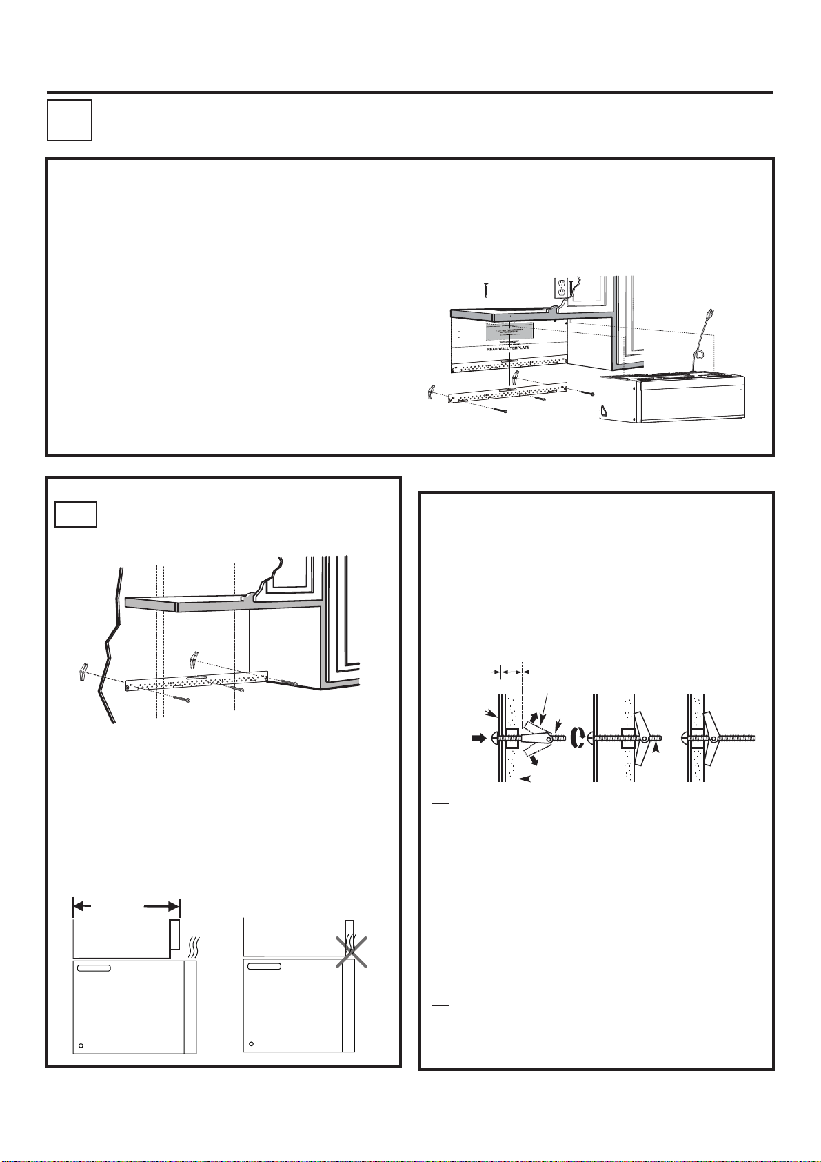
Remove the toggle wings from the bolts.
1
Insert the bolts into the mounting plate
2
E
G
ED
O
T
"
8
/
3
S
N
m
12"
d
4"
s
e
h
t
n
i
s
le
o
h
th
wi
F
O
E
ID
S
R
E
H
T
EI
N
O
D
Y
L
N
E
EV
L,
A
N
IO
T
I
ADD
E
AT
L
P
G
IN
NT
U
O
M
E
.
ne
i
l
.
e
n
li
d
e
t
ot
d
e
h
t
g
n
o
l
a
e
t
a
l
p
m
e
t
l
l
a
w
r
ea
r
e
h
t
rim
T
e
n th
i
es
l
o
h
h
wit
gn
i
l
a
to
es
ol
h
k
mar
nd
a
e
t
a
c
Lo
.
e
ta
l
p
g
n
it
n
u
o
m
:
NT
A
RT
IMPO
F
O
E
D
I
S
R
HE
N EIT
O
D
U
ST
E
ON
T
EAS
L
T
A
E
T
CA
O
L
E.
IN
L
ER
T
EN
C
THE
LY
EN
V
E
L,
A
N
O
I
T
DDI
A
2
R
O
F
N
IO
T
A
C
LO
HE
T
RK
A
M
ATE
L
P
ING
UNT
E MO
H
T
N
TS I
L
O
B
E
GL
G
O
T
D
E
AC
P
S
.
A
E
R
A
through the holes designated to go into
drywall and reattach the toggle wings to
3⁄4"(19 mm) onto each bolt.
Attach the plate to the wall using toggle
bolts. At least one wood screw must be used
to attach the plate to a wall stud.
NOTE: If the cabinet depth including the
cabinet doors is more than 13'""' then the
unit must be spaced out from wall using
adequate materials supporting150 Ibs to
allow proper top vent air exhaust/intake.
13.8" MAX.
(35 cm)
Cabinet
Cabinet
To use toggle bolts:
Spacing for Toggles
More Than Wall
Thickness
Mounting
Plate
Place the mounting plate against the wall
3
and insert the toggle wings into the holes in
the wall to mount the plate.
NOTE: Before tightening toggle bolts and
wood screw, make sure the bottom of the
mounting plate touch the bottom of the
cabinet when pushed flush against the wall
and that the plate is properly centered under
the cabinet.
CAUTION:Be careful to avoid pinching fingers
between the back of the mounting plate and
the wall.
Tighten all bolts. Pull the plate away from
4
the wall to help tighten the bolts.
Toggle Wings
Toggle
Bolt
Wall
Bolt End
EN-10
Page 12
Installation Instructions
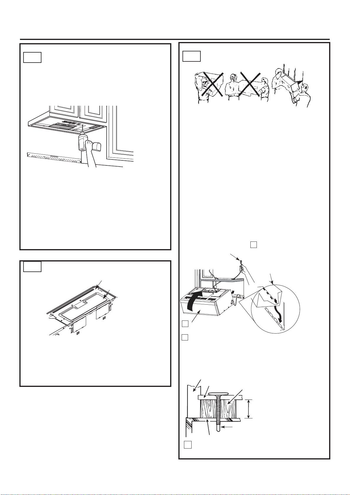
A2.
A3.
USE TOP CABINET TEMPLATE
FOR PREPARATION OF TOP
CABINET
You need to drill holes for the top support
screws and a hole large enough for the power
cord to fit through.
• Read the instructions on the TOP CABINET
TEMPLATE.
• Tape it underneath the top cabinet.
NOTE:Adjust top template accordingly if
the microwave is being spaced out from the
wall due to cabinet depth (including cabinet
doors) of more th n 13''.
• Drill the holes, following the instructions on
the TOP CABINET TEMPLATE.
CAUTION:Wear safety goggles when drilling
holes in the cabinet bottom.
CHECK BLOWER PLATE
Blower Plate
Cover Plate
A4.
MOUNT THE MICROWAVE OVEN
FOR EASIER INSTALLATION AND PERSONAL
SAFETY, WE RECOMMEND THAT TWO
PEOPLE INSTALL THIS MICROWAVE OVEN.
IMPORTANT: Do not grip or use the handle or
heat shield during installation. Do not remove
the cardboard spacers between the heat
shield and door.
NOTE: If your cabinet is metal, use the nylon
grommet around the power cord hole to
prevent cutting of the cord.
NOTE: We recommend using filler blocks if
the cabinet front hangs below the cabinet
bottom shelf.
IMPORTANT: If filler blocks are not used,
case damage may occur from overtightening
screws.
NOTE: When mounting the
microwave oven, thread
power cord through hole in
bottom of top cabinet. Keep
it tight throughout Steps
1–3. Do not pinch cord or
lift oven by pulling cord.
Lift microwave, tilt
1
it forward, and hook
slots at back bottom
edge onto four lower
tabs of mounting
plate.
• Place the microwave in its upright position,
with the top of the unit facing up.
• Check to see that the blower plate and
cover plate are correctly installed on the
unit.
EN-11
Rotate front of oven
2
up against cabinet
bottom.
Insert a self-aligning screw through top center
3
cabinet hole. Temporarily secure the oven by
turning the screw at least two full turns after
thethreads have engaged.(It will be completelytightened later.) Be sure to keep power cordtight. Be careful not to pinch the cord, especiallywhen mounting flush to bottom of cabinet.
Cabinet Front
Cabinet Bottom Shelf
Filler Block
Equivalent to Depth
of Cabinet Recess
Self-Aligning Screw
Microwave Oven Top
Attach the microwave oven to the top
4
cabinet.
Page 13
Installation Instructions
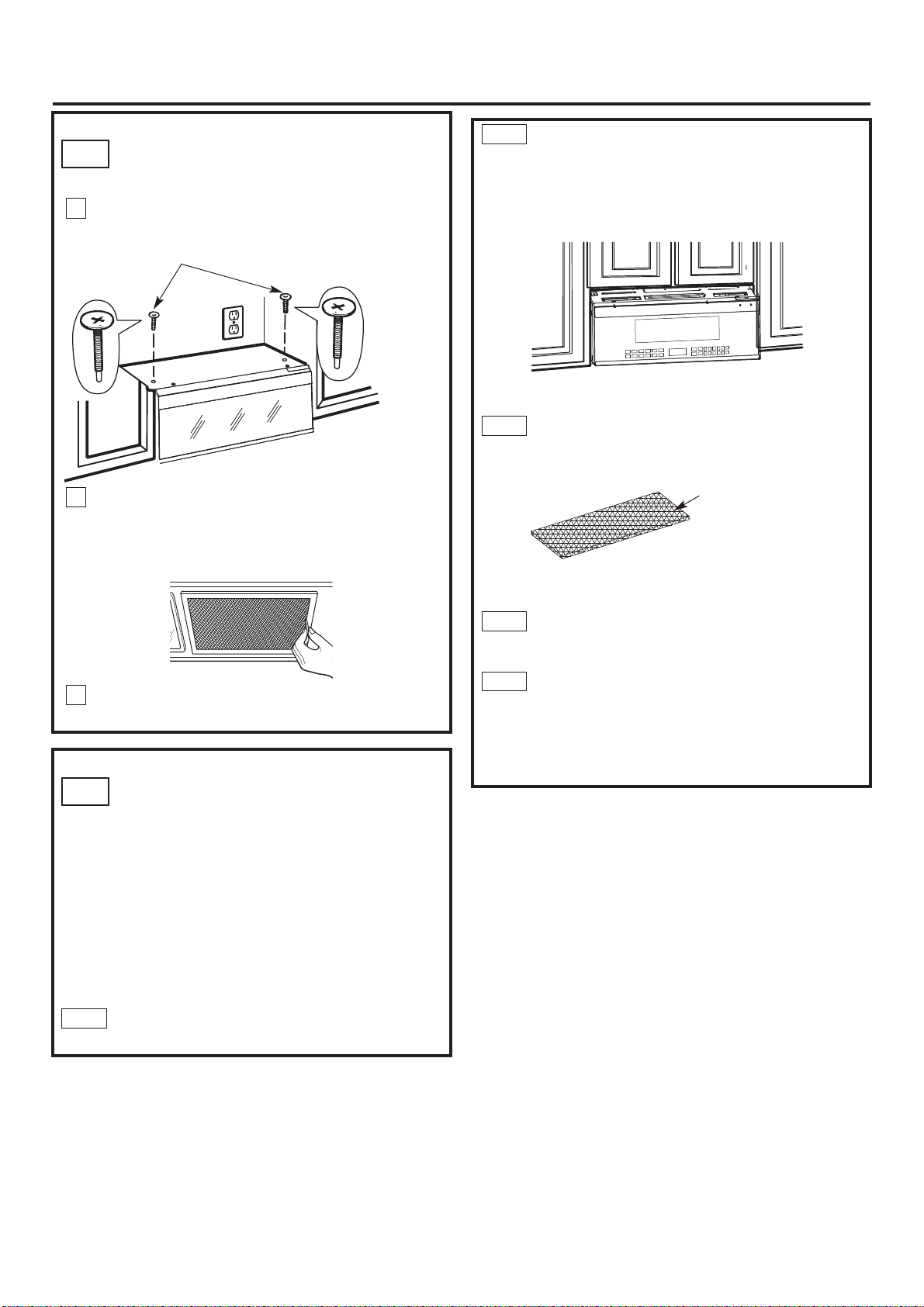
MOUNT THE MICROWAVE
A4.
OVEN
5
Insert 2 self-aligning screws through outer
top cabinet holes. Turn two full turns on
each screw.
6
Tighten the outer two screws to the top
of the microwave oven. (While tightening
screws, hold the microwave oven in place
against the wall and the top cabinet.)
(cont.)
A 5.2
A 5.3
Remove the plastic air guide located on
the top of the microwave.
Change the charcoal filter.
Charcoal
Filter
7
Install grease filters. See the Use & Care
Manual packed with the microwave.
INSTALLING OR CHANGE
A5.
THE CHARCOAL FILTER
(Some Models)
NOTE: The charcoal filter is factory installed
in some models. Refer to the Use and Care
to see if yours is factory installed and for
replacement information.
For models without the recirculation filter
access door,follow these steps to replace or
install a charcoal filter.
A 5.1
Unplug microwave oven or disconnect
power.
A 5.4
A 5.5
Install the plastic air guide located on
the top of the microwave.
Close the microwave door. Plug in
microwave oven or reconnect power.
EN-12
Page 14
Installation Instructions
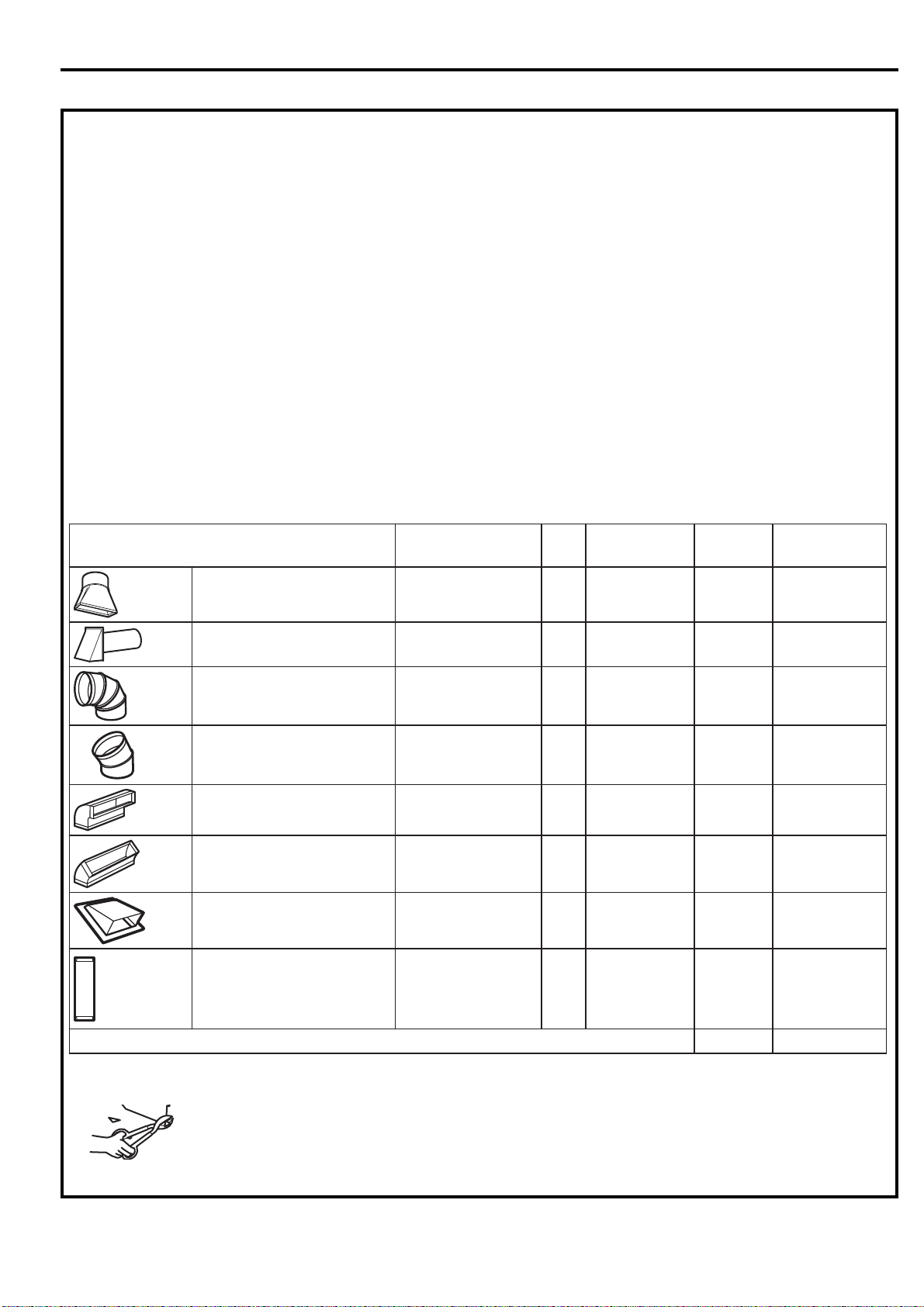
INSTALLATION INSTRUCTIONS FOR EXTERNAL EXHAUST DUCTING
NOTE: If you need to install ducts, note that the
total duct length of 34" x 10" (8.2 x 25.4 cm)
rectangular or 5" (12.7 cm) diameter/ 6" (15.2
cm) diameter round duct should not exceed
140 equivalent feet (42.7 m).Outside ventilation
requires an EXTERNAL EXHAUST DUCT. Read
the following carefully. NOTE: It is important
that venting be installed using the most direct
route and with as few elbows as possible. This
ensures clear venting of exhaust and helps prevent
blockages. Also, make sure dampers swing freely
and nothing is blocking the ducts.
Exhaust connection:
The exhaust adaptor has been designed to
mate with a standard 34" x 10" (8.2 x 25.4 cm)
rectangular duct. If a round duct is required, a
rectangular-to-round transition adaptor must be
used. "A5 "(12.7cm)/ "6"(15.2cm) diameter duct is
acceptable to use.
DUCT PIECES
EQUIVALENT
LENGTH
Maximum duct length:
For satisfactory air movement, the total duct
length of 34" x 10" (8.2 x 25.4 cm) rectangular or
5" (12.7 cm) diameter/6" (15.2 cm) diameter round
duct should not exceed 140 equivalerfeet (42.7 m).
Elbows, transitions, wall and roof caps,
etc.,
present additional resistance to airflow and
are equivalent to a section of straight duct
which is longer than their actual physical size.
When calculating the total duct length, add the
equivalent lengths of all transitions and adaptors
plus the length of all straight duct sections.The
chart below shows you how to calculate total
equivalent ductwork length using the approximate
feet of equivalent length of some typical ducts.
x
NUMBER
USED
=
EQUIVALENT
LENGTH
Rectangular-to-Round
Transition Adaptor*
Wall Cap 40 Ft. (12.2 m) x ( ) = Ft. or m
90° Elbow 10 Ft. (3 m) x ( ) = Ft. or m
45° Elbow 5 Ft. (1.5 m) x ( ) = Ft. or m
90° Elbow 25 Ft. (7.6 m) x ( ) = Ft. or m
45° Elbow 5 Ft. (1.5 m) x ( ) = Ft. or m
Roof Cap 24 Ft. (7.3 m) x ( ) = Ft. or m
Straight Duct 6“ (15.2
cm) Round or 31⁄4“ x 10“
(8.2 x 25.4 cm
Rectangular)
Total Ductwork = Ft. or m
5 Ft. (1.5 m) x ( ) = Ft. or m
1 Ft. (0.3 m) x ( ) = Ft. or m
* IMPORTANT: If a rectangular-toround transition adaptor is used,
the bottom corners of the damper
will have to be cut to fit, using the
tin snips, in order to allow free
movement of the damper.
EN-13
Equivalent lengths of duct pieces are based on
actual tests and reflect requirements for good
venting performance with any vent hood.
Page 15
Installation Instructions
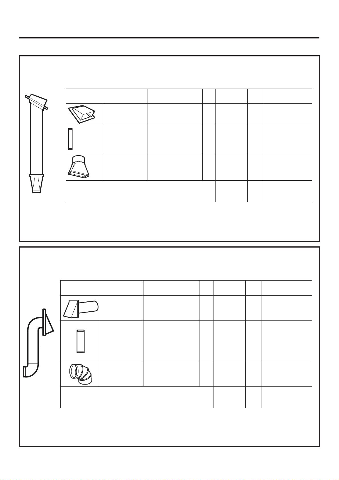
EXTERNAL EXHAUST DUCTING
OUTSIDE TOP EXHAUST (EXAMPLE ONLY)
The following chart describes an example of one possible ductwork installation.
DUCT PIECES
Roof Cap 24 Ft. (7.3 m) x ( 1 ) = 24 Ft. (7.3 m)
12 Ft. (3.6 m)
Straight Duct
(6”/15.2 cm
Round)
Rectangularto-Round
Transition
Adaptor*
Equivalent lengths of duct pieces are based on actual
tests and reflect requirements for good venting
performance with any vent hood.
* IMPORTANT: If a rectangular-to-round transition adaptor is used, the bottom corners of
the damper will have to be cut to t, using the tin snips, in order to allow free movement of
the damper.
EQUIVALENT
LENGTH
12 Ft. (3.6 m) x ( 1 ) = 12 Ft. (3.6 m)
5 Ft. (1.5 m) x ( 1 ) = 5 Ft. (1.5 m)
x
NUMBER
USED
Total
Length
OUTSIDE BACK EXHAUST (EXAMPLE ONLY)
The following chart describes an example of one possible ductwork installation.
EQUIVALENT
=
LENGTH
41 Ft. (12.5 m)
DUCT PIECES
Wall Cap 40 Ft. (12.2 m) x ( 1 ) = 40 Ft. (12.2 m)
3 Ft. Straight
Duct
(31⁄4” x
10”/8.2 x
25.4 cm
Rectangular)
90° Elbow 10 Ft. (3 m) x ( 1 ) = 20 Ft. (6.1 m)
Equivalent lengths of duct pieces are based on actual
tests and reflect requirements for good venting
performance with any vent hood.
NOTE: For back exhaust, care should be taken to align exhaust with space between studs,
or wall should be prepared at the time it is constructed by leaving enough space between
the wall studs to accommodate exhaust.
EQUIVALENT
LENGTH
3 Ft. (0.9 m) x ( 1 ) = 3 Ft. (0.9 m)
x
NUMBER
USED
Total
Length
EQUIVALENT
=
LENGTH
63 Ft. (19.2 m)
EN-14
Page 16
Installation Instructions
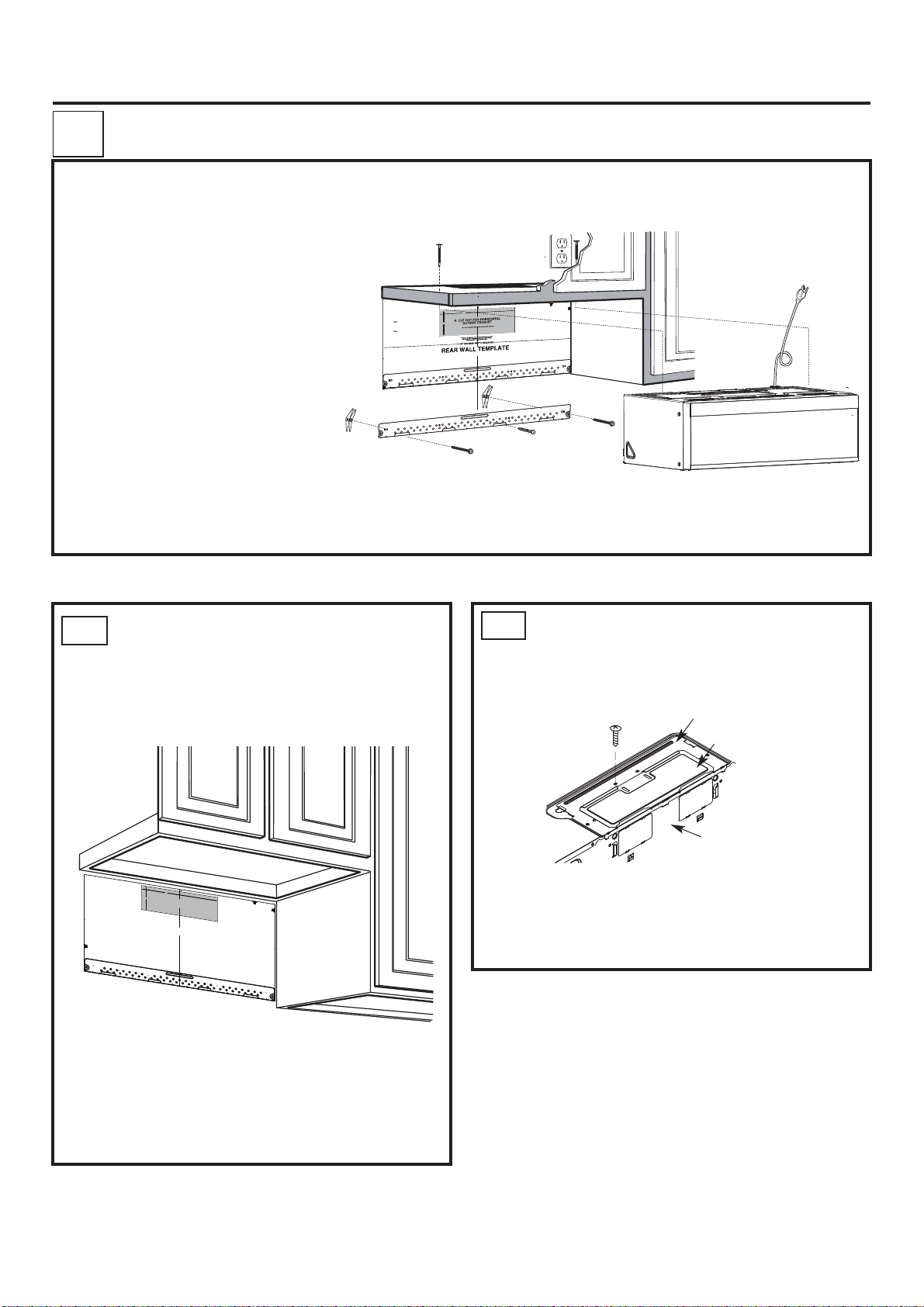
OUTSIDE BACK EXHAUST (Horizontal Duct)
B
INSTALLATION OVERVIEW
B1. Prepare Rear Wall
B2. Remove Blower Plate
B3. Attach Mounting Plate to
Wall
B4. Prepare Top Cabinet
B5. Adjust Blower
B6. Mount the Microwave Oven
IMPORTANT NOTES:
• Make sure the screws for the
blower motor and blower plate
are securely tightened when
they are reinstalled. This will
help to prevent excessive
vibration.
• Make sure the motor wiring
has been properly routed and
secured, and that the wires are
not pinched.
O
T
NT
TA
R
O
P
M
I
RY
E
V
IT IS
:
TE
O
N
S
N
IO
CT
RE
I
D
HE
T
W
O
L
L
FO
D
N
A
D
A
RE
S
ION
CT
U
R
T
NS
I
N
O
I
T
A
L
L
A
T
S
N
I
THE
N
I
IS
H
T
ITH
W
DING
E
CE
O
R
P
RE
O
F
E
B
.
TE
A
L
MP
E
T
L
L
A
W
R
A
RE
m
otto
b
e
th
n
o
ti
i
s
o
p
o
t
s
e
v
r
e
s
e
t
a
l
p
m
e
T
ll
Wa
r
a
e
R
s
hi
T
t
s
hau
ex
l
ta
n
o
z
i
r
o
h
e
h
t
te
a
c
o
d to l
an
e
t
a
l
p
g
n
ti
n
u
o
m
t.
e
tl
u
o
d
e
on
iti
s
o
p
s
i
te
a
l
p
m
e
t
e
h
t
t
a
h
k t
ec
ch
o
t
l
ve
e
l
a
e
Us
.
1
y.
l
e
at
r
cu
ac
or
t
f
e
l
e
n th
o
d
stu
e
n
o
t
s
a
e
l
t
a
k
r
a
m
d
n
a
e
t
ca
o
2. L
.
e
in
l
r
e
t
n
e
the c
f
o
e
d
t si
h
g
i
r
wood
e
n
o
t
as
e
l
t
a
e
us
o
t t
an
t
r
o
p
im
is
It
t
h
g
ei
w
e
h
t
t
or
p
sup
o
tud t
s
n a
y i
l
m
r
fi
d
e
t
n
u
o
w m
e
r
c
s
ed
c
a
ysp
nl
ve
e
l,
a
n
o
i
ddit
a
wo
t
k
ar
M
.
ave
w
o
cr
i
m
e
th
f
o
s.
t
l
o
b
gle
g
o
t
ed
i
l
pp
u
s
e
th
or
f
s
n
atio
c
o
l
s
i
e
r
e
th
e
r
he
W
.
s
n
o
i
t
ca
lo
d
e
ark
m
e
th
n
i
s
ole
h
ll
i
r
D
s
3.
le
o
h
r
o
F
.
ws
e
r
c
s
d
woo
or
f
le
o
h
"
6
1
/
3
a
ill
dr
,
d
u
t
a s
r
o
s f
le
o
h
"
8
/
5
l
il
r
d
d,
tu
s
a
ith
w
p
u
e
in
l
not
o
d
t
ha
t
.
ts
l
bo
e
l
gg
o
t
E
LAT
P
G
N
I
T
N
U
MO
HE
L T
NSTAL
I
T
O
DO N
.
E
IM
T
S
HI
T
AT
wall.
r
a
e
r
e
h
t
m
o
r
f
e
t
la
p
m
te
e
th
e
ov
m
e
R
.
4
r
u
o
y
r
o
f
k
o
o
b
n
io
t
c
u
r
st
n
I
n
tio
a
ll
a
st
n
I
e
h
t
w
e
i
v
e
R
5.
.
on
i
t
a
u
t
i
n s
o
i
at
ll
sta
in
a
l
r
a
t
l
u
s
on
c
a
r
a
p
a
j
o
h
a
l
a
a
t
l
e
u
v
e
l
r
a
D
l.
o
ñ
a
p
s
E
n
e
n
ó
i
s
r
e
v
e
h
t
n
i
s
le
o
h
h
t
i
w
n
g
i
l
a
o
t
s
le
ho
k
r
a
d m
n
a
e
t
ca
Lo
e.
t
a
l
p
g
tin
n
u
o
m
:
NT
A
RT
O
P
M
I
F
O
E
ID
S
ER
H
T
N EI
O
D
TU
S
E
ON
T
S
EA
L
T
A
E
T
A
C
LO
.
E
LIN
R
E
T
N
E
C
E
H
T
Y
L
L, EVEN
A
N
IO
T
ADDI
2
R
FO
ON
TI
A
C
O
HE L
T
K
AR
M
E
T
A
PL
ING
NT
U
MO
HE
T
N
I
S
T
L
BO
E
L
OGG
T
D
CE
A
P
S
.
EA
R
A
.
e
n
d li
e
t
t
o
d
e
th
g
on
l
a
e
t
a
pl
m
e
l t
l
a
w
r
a
e
r
he
t
rim
T
E
G
D
E
TO
"
8
/
3
12"
"
4
L
m
M
I
L
T
M
S
AR
.
e
n
li
d
e
t
t
o
d
e
h
t
g
lon
a
e
t
a
l
mp
e
t
l
al
w
r
a
e
r
e
h
t
rim
T
e
h
t
n
i
es
l
ho
h
it
w
n
g
i
l
a
o
t
s
e
l
o
h
k
r
a
m
nd
a
te
a
c
o
.
e
t
a
l
i
p
n
g
n
t
u
o
:
T
N
A
T
R
O
P
OF
E
D
I
S
R
THE
N EI
O
D
U
ST
E
ON
T
S
A
E
L
AT
E
T
CA
O
E.
N
I
L
R
E
T
N
E
C
E
H
Y
L
N
E
EV
,
L
A
N
O
ITI
DD
A
2
R
FO
N
IO
CAT
O
L
HE
T
RK
A
E
T
A
L
P
G
IN
T
OUN
M
E
H
T
IN
S
T
L
O
B
E
L
GG
TO
D
CE
A
P
.
A
E
PREPARING THE REAR
B1.
WALL FOR OUTSIDE BACK
EXHAUST
You need to cut an opening in the rear wall
for outside exhaust.
NO
TE
: IT IS VE
R
E
RY IM
AD
A
POR
ND
FOLL
T
IN T
AN
T
OW
HE INSTA
TO
TH
E
DIR
BEFO
L
LATIO
ECTIONS
RE
N
PR
INSTR
OCEED
RE
AR
U
CTIO
W
ING
ALL
NS
WITH
TEMPLA
T
h
is
THI
Rear
S
TE
W
all
.
m
T
e
ount
m
pl
in
a
t
g
e s
p
l
er
a
t
e
v
es
ou
a
nd
t
t
let
o
t
p
o
.
osit
lo
c
i
a
on
t
e
t
t
h
he
1.
e
Us
bot
h
or
e
t
i
om
z
a
o
ntal
le
vel
exhaust
t
o
check
accurat
that
ely.
t
h
e
2.
t
e
Locat
m
pla
t
e
e
and
is
posi
m
ark
t
ione
right
a
t
d
side
l
ea
s
t
o
on
f
t
e
h
01
e
st
ce
ud
n
6
on the
t
'
er
l
ine.
It
is
l
ef
im
t
or
port
scr
ew
ant
mou
t
o
u
se at
n
t
e
d
of
leas
f
irmly
th
e
t
m
on
in
i
crow
e
a
st
wo
u
ave.
o
d
loca
d
t
o
Ma
s
ti
up
on
r
port
k
s
t
wo
f
or
t
he
t
a
h
ddition
e
wei
3.
s
Dr
uppl
ght
ill
al
ied
h
,
oles
e
v
t
og
enly
in
g
le
t
spa
h
bolt
e
a st
m
ced
s.
ark
ud,
ed
dri
l
ll
oca
a
3
t
io
/
t
1
hat
n
6"
s.
Wh
ho
do
le
n
ere
f
ot li
o
r
t
wood
ne
h
er
t
up
oggle
e
i
s
screws.
with
b
olt
a stu
s
.
F
o
d,
01
r
dr
hol
il
6
l
es
5
'
/
8
"
D
hole
O
NOT
s
f
or
AT
IN
T
S
HI
T
S
ALL
T
I
M
T
E.
HE
4.
Rem
M
O
UN
o
ve
T
I
NG
t
he
P
5.
t
em
LAT
R
plat
eview
E
e
from
th
e I
t
nsta
he
in
rear
l
st
la
allat
t
io
wall.
n
io
In
n
s
tr
sit
uc
u
t
a
ion
t
io
n.
bo
o
k
f
or
y
our
Darle
vu
elta
a
ve
la
r
ho
sión
ja
pa
en
r
a
Españ
co
n
sul
ol.
tar
la
Lo
cate
and
mark hol
mou
es to
nti
ng p
alig
late
n with ho
.
IMP
O
l
RTA
es
in the
NT:
LOCATE
AT LE
A
TH
ST ON
E
C
E
E
NTER
STU
D
LIN
O
M
E
N
A
.
EITH
R
K TH
ER
E L
S
OC
ID
E
SP
AT
O
ACE
ION FOR
F
D TOGG
2 AD
AREA.
LE BO
D
IT
I
O
LTS IN
NAL
,
EVEN
TH
E
MOU
LY
NTIN
G
PLA
TE
Trim
the
r
ea
r wa
ll te
mpla
te a
l
o
n
g the d
otted
line.
• Read the instructions on the REAR
WALL TEMPLATE.
• Tape it to the rear wall.
• Cut the opening, following the instructions
of the REAR WALL TEMPLATE.
3
/
8" TO E
D
GE
1
2
"
4"
(
%76176(14*14+<106#.
1765+&'':*#756
%7
6
*1.
'
6
*
4
17
)*
4'#
49#..
(
14
':*
#
7
56#
&
#
26
1
%#
7
6
+10Ä+(':*
4
'
#
%
7
1//
5
6
#
&
'0&
#2614
'&
&+5%
&
+5215+
+/'0
5+1
6
*
+1
0)4
#
4)'
0
'&
'#5'Ä.
17
+
0
6
6
1*
5+&
#
1
'
&'0
7
5
'
#+4
56
4
/+0+/7/9+&6*4'37+4'&
9+.
7
%
6
.
74
'
4'#49#..6'/2.#6'
%
&
Tri
m
the
r
ea
r
wal
l
te
mpla
te
a
l
o
ng
the
d
otted
lin
e
4
%
.
Lo
cate
and
ma
r
k hol
mo
unti
es to
ng
a
p
lig
late
n w
.
ith h
IMPORTA
o
les
in the
NT:
LO
CAT
E
AT LE
AST ON
TH
E CE
E
N
STU
TER
D O
LIN
MA
E.
N EIT
RK TH
H
ER
E
L
SIDE
OCAT
SP
O
ACE
IO
F
N FOR
D
TOGG
2 AD
AR
LE
DIT
BO
EA.
I
O
LTS
NAL
IN
, EVEN
THE
M
LY
OU
NTI
N
G PLATE
#$
B2.
REMOVE BLOWER PLATE
Remove and save the screw that holds the
blower plate to the microwave. Lift off the
blower plate.
Blower Plate
Cover Plate
Back of
Microwave
• The cover plate is installed with the blower
plate, no need to separate.
EN-15
Page 17
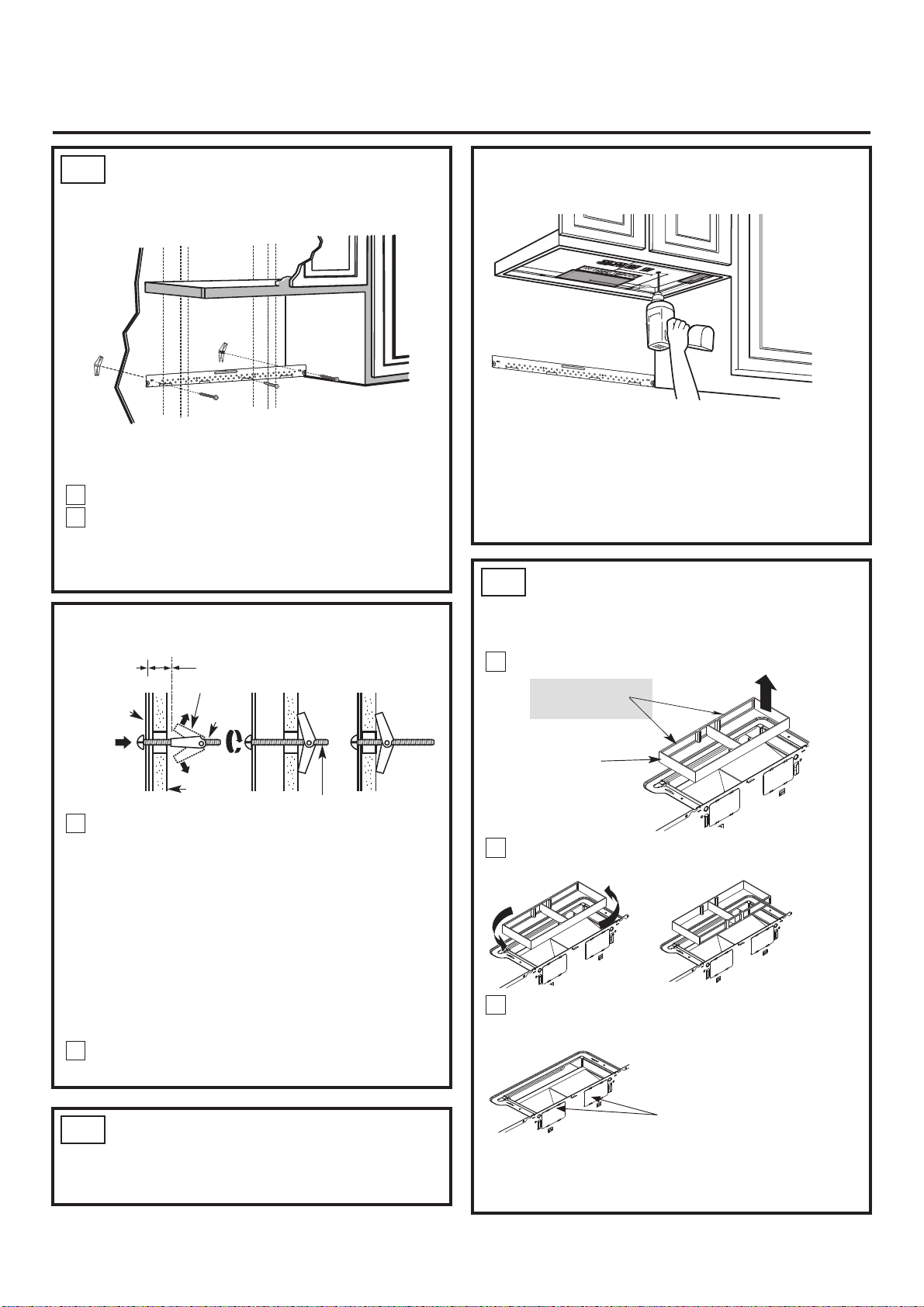
Installation Instructions
B3.
ATTACH THE MOUNTING
PLATE TO THE WALL
Attach the plate to the wall using toggle
bolts. At least one wood screw must be used
to attach the plate to a wall stud.
Remove the toggle wings from the bolts.
1
Insert the bolts into the mounting plate
2
through the holes designated to go into
drywall and reattach the toggle wings to
3⁄4"(19 mm) onto each bolt.
To use toggle bolts:
Spacing for Toggles More
Than Wall Thickness
Mounting
Plate
Toggle Wings
Toggle
Bolt
You need to drill holes for the top support
screws and a hole large enough for the power
cord to fit through.
• Read the instructions on the TOP CABINET
TEMPLATE.
• Tape it underneath the top cabinet.
• Drill the holes, following the instructions on
the TOP CABINET TEMPLATE.
CAUTION:Wear safety goggles when drilling
holes in the cabinet bottom.
B5.
ADAPTING MICROWAVE AIR
DIRECTOR FOR OUTSIDE
BACK EXHAUST
Carefully pull out the air director.
1
Before:
Openings Facing
Forward
Wall
Place the mounting plate against the wall
3
and insert the toggle wings into the holes in
the wall to mount the plate.
NOTE: Before tightening toggle bolts and
wood screw, make sure the bottom of the
mounting plate touch the bottom of the
cabinet when pushed flush against the wall
and that the plate is properly centered under
the cabinet.
CAUTION:Be careful to avoid pinching fingers
between the back of the mounting plate and
the wall.
Tighten all bolts. Pull the plate away from
4
the wall to help tighten the bolts.
B4.
USE TOP CABINET TEMPLATE
Bolt End
FOR PREPARATION OF TOP
CABINET
Air Director
Rotate the air director counterclockwise 180°
2
Before Rotation After Rotation
Remove the knockout plates in the back of
3
the unit with snips. (For some models)
Knockout Plates:
Snip all 4 webs on
each knockout panel
and remove the metal
Back of microwave
knockouts for rear airflow.
Please take care to
remove any sharp edges
created from removing
the knockout plates.
EN-16
Page 18
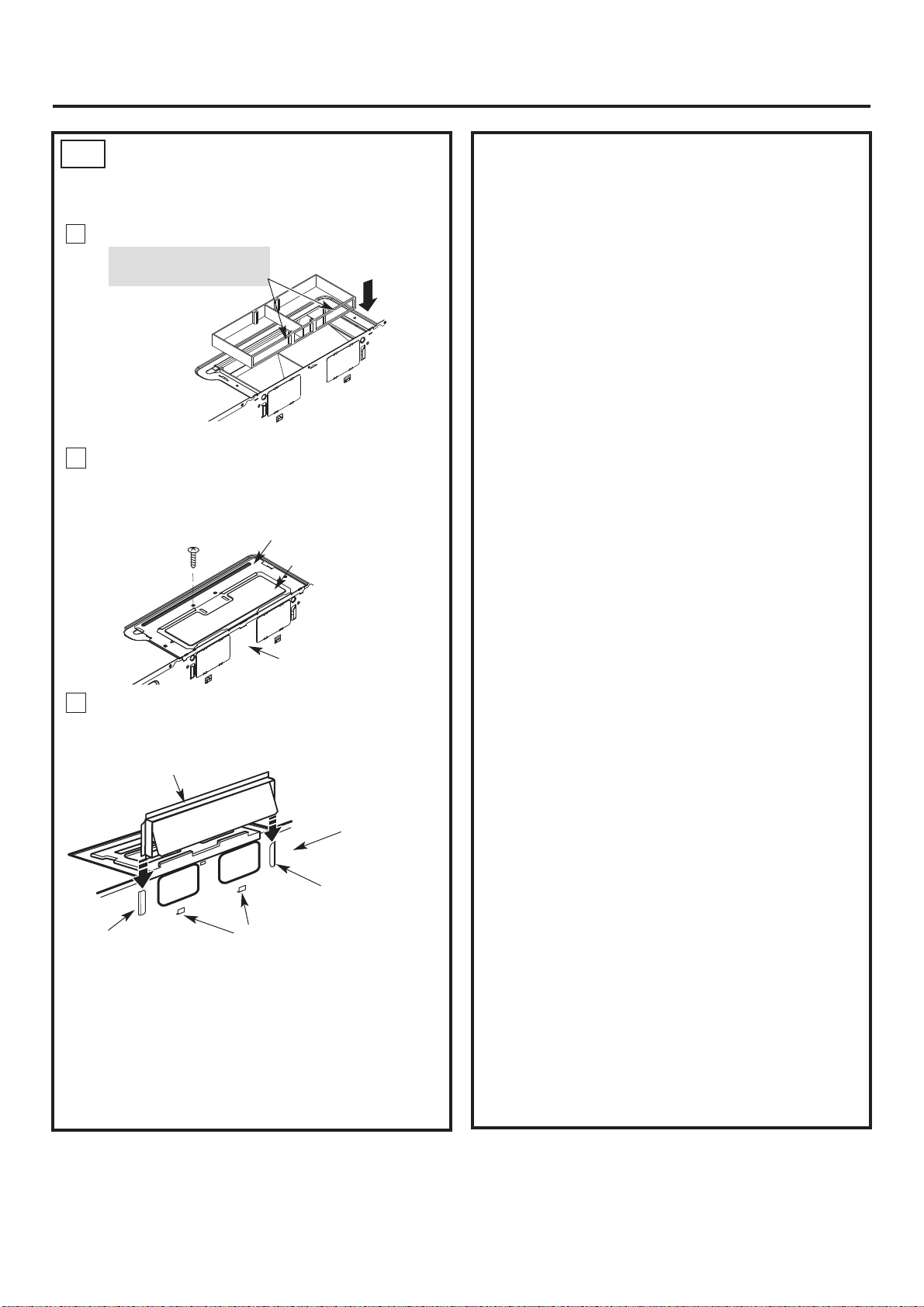
Installation Instructions
B5.
ADAPTING MICROWAVE
BLOWER FOR OUTSIDE
BACK EXHAUST (cont.)
Place the air director back into the opening.
4
AFTER: Air Director
Openings Facing Back
5
Secure the blower plate to the microwave
with the original screw.
Blower Plate
Cover Plate
Back of
Microwave
6
Attach the exhaust adaptor to the rear of
the oven by sliding it into the guides at the
top center of the back of the oven.
Adaptor
Back of
Microwave
Guide
Guide
Push in securely until it is in the lower locking
tabs. Take care to assure that the damper
hinge is installed so that it is at the top and
that the damper swings freely.
Locking Tabs
Left Blank Intentionally
EN-17
Page 19
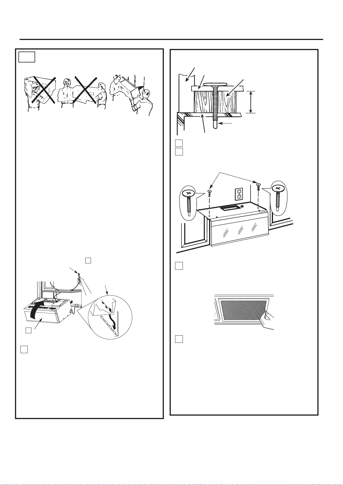
Installation Instructions
B6.
MOUNT THE MICROWAVE
OVEN
Cabinet Front
Cabinet Bottom Shelf
Filler Block
FOR EASIER INSTALLATION AND PERSONAL
SAFETY, WE RECOMMEND THAT TWO
PEOPLE INSTALL THIS MICROWAVE OVEN.
IMPORTANT: Do not grip or use the handle or
heat shield during installation. Do not remove
the cardboard spacers between the heat
shield and door.
NOTE: If your cabinet is metal, use the nylon
grommet around the power cord hole to
prevent cutting of the cord.
NOTE: We recommend using filler blocks if
the cabinet front hangs below the cabinet
bottom shelf.
IMPORTANT: If filler blocks are not used,
case damage may occur from overtightening
screws.
NOTE: When mounting the
microwave oven, thread
power cord through hole in
bottom of top cabinet. Keep
it tight throughout Steps 1–3.
Do not pinch cord or lift
oven by pulling cord.
Lift microwave, tilt it
1
forward, and hook slots at
back bottom edge onto four
lower tabs of mounting
plate.
Self-Aligning Screw
Microwave Oven Top
Place the air director back into the opening.
4
5
Insert 2 self-aligning screws through outer
Equivalent to Depth
of Cabinet Recess
top cabinet holes. Turn two full turns on
each screw.
6
Tighten the outer two screws to the top
of the microwave oven. (While tightening
screws, hold the microwave oven in place
against the wall and the top cabinet.)
2
Rotate front of oven
up against cabinet
bottom.
Insert a self-aligning screw through top
3
center cabinet hole. Temporarily secure the
oven by turning the screw at least two full
turnsa fter the threads have engaged. (It
will be completely tightened later.) Be sure
to keep power cord tight. Be careful not to
pinch the cord, especially when mounting
flush to bottom of cabinet.
7
Install grease filters. See the Use & C are
manual packed with the microwave.
IMPORTANT: Remove the cardhoard spacers
between heat shield and door.
EN-18
Page 20
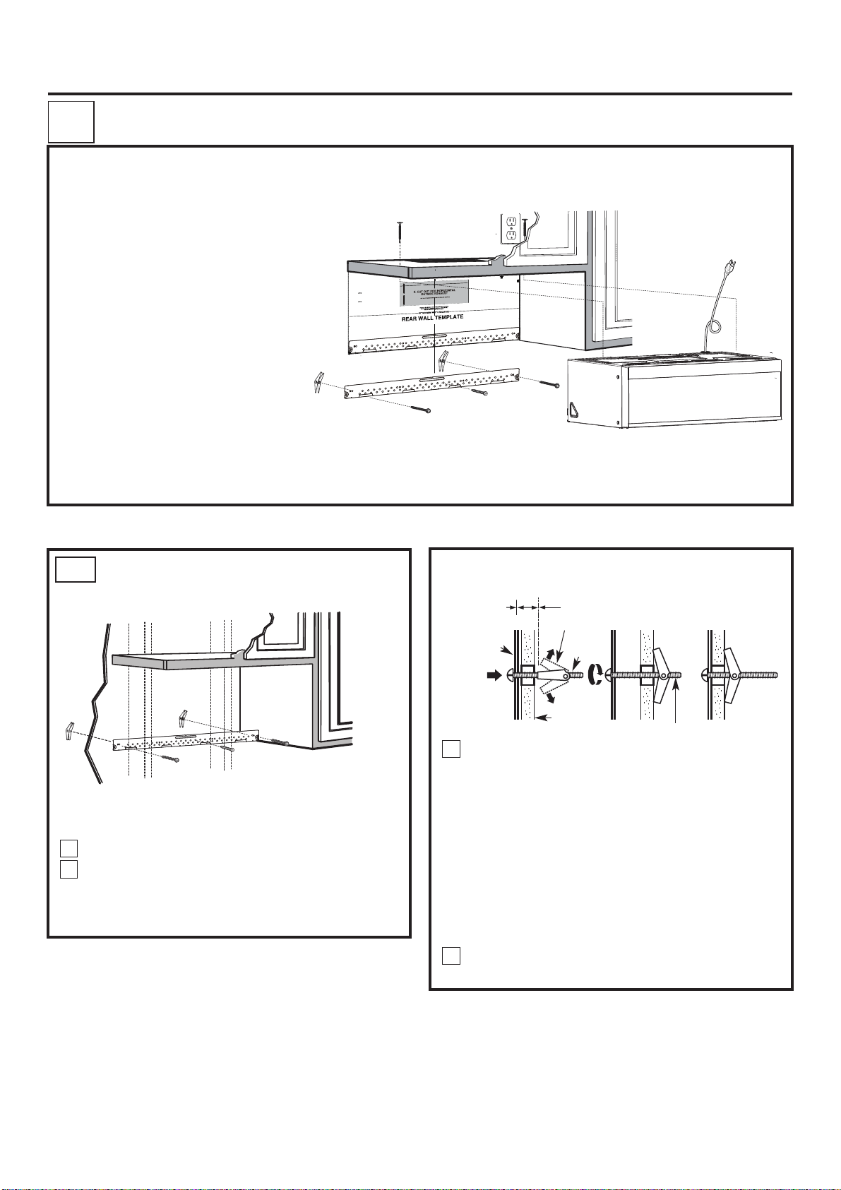
Installation Instructions
OUTSIDE TOP EXHAUST (Vertical Duct)
C
INSTALLATION OVERVIEW
C1. Attach Mounting Plate to Wall
C2.Prepare Top Cabinet
C3.Adapting Microwave Blower
for Outside Top Exhaust
C4.Check Damper Operation
C5.Mount Microwave Oven
C6.Adjust Exhaust Adaptor
C7.Connect Ductwork
IMPORTANT NOTES:
• • Make sure the screws for
the blower motor and blower
plate are securely tightened
when they are reinstalled. This
will help to prevent excessive
vibration.
• Make sure the motor wiring
has been properly routed and
secured, and that the wires are not pinched.
O
T
NT
TA
R
O
P
M
I
RY
E
V
IT IS
:
TE
O
N
S
N
IO
CT
RE
I
D
HE
T
W
O
L
L
FO
D
N
A
D
A
RE
S
ION
CT
U
R
T
NS
I
N
O
I
T
A
L
L
A
T
S
N
I
THE
N
I
IS
H
T
ITH
W
DING
E
CE
O
R
P
RE
O
F
E
B
.
TE
A
L
MP
E
T
L
L
A
W
R
A
RE
m
otto
b
e
th
n
o
ti
i
s
o
p
o
t
s
e
v
r
e
s
e
t
a
l
p
m
e
T
ll
Wa
r
a
e
R
s
hi
T
t
s
hau
ex
l
ta
n
o
z
i
r
o
h
e
h
t
te
a
c
o
d to l
an
e
t
a
l
p
g
n
ti
n
u
o
m
t.
e
tl
u
o
d
e
on
iti
s
o
p
s
i
te
a
l
p
m
e
t
e
h
t
t
a
h
k t
ec
ch
o
t
l
ve
e
l
a
e
Us
.
1
y.
l
e
at
r
cu
ac
or
t
f
e
l
e
n th
o
d
stu
e
n
o
t
s
a
e
l
t
a
k
r
a
m
d
n
a
e
t
ca
o
2. L
.
e
in
l
r
e
t
n
e
the c
f
o
e
d
t si
h
g
i
r
wood
e
n
o
t
as
e
l
t
a
e
us
o
t t
an
t
r
o
p
im
is
It
t
h
g
ei
w
e
h
t
t
or
p
sup
o
tud t
s
n a
y i
l
m
r
fi
d
e
t
n
u
o
w m
e
r
c
s
ed
c
a
ysp
nl
ve
e
l,
a
n
o
i
ddit
a
wo
t
k
ar
M
.
ave
w
o
cr
i
m
e
th
f
o
s.
t
l
o
b
gle
g
o
t
ed
i
l
pp
u
s
e
th
or
f
s
n
atio
c
o
l
s
i
e
r
e
th
e
r
he
W
.
s
n
o
i
t
ca
lo
d
e
ark
m
e
th
n
i
s
ole
h
ll
i
r
D
s
3.
le
o
h
r
o
F
.
ws
e
r
c
s
d
woo
or
f
le
o
h
"
6
1
/
3
a
ill
dr
,
d
u
t
a s
r
o
s f
le
o
h
"
8
/
5
l
il
r
d
d,
tu
s
a
ith
w
p
u
e
in
l
not
o
d
t
ha
t
.
ts
l
bo
e
l
gg
o
t
E
LAT
P
G
N
I
T
N
U
MO
HE
L T
NSTAL
I
T
O
DO N
.
E
IM
T
S
HI
T
AT
wall.
r
a
e
r
e
h
t
m
o
r
f
e
t
la
p
m
te
e
th
e
ov
m
e
R
.
4
r
u
o
y
r
o
f
k
o
o
b
n
io
t
c
u
r
st
n
I
n
tio
a
ll
a
st
n
I
e
h
t
w
e
i
v
e
R
5.
.
on
i
t
a
u
t
i
n s
o
i
at
ll
sta
in
a
l
r
a
t
l
u
s
on
c
a
r
a
p
a
j
o
h
a
l
a
a
t
l
e
u
v
e
l
r
a
D
l.
o
ñ
a
p
s
E
n
e
n
ó
i
s
r
e
v
e
h
t
n
i
s
le
o
h
h
t
i
w
n
g
i
l
a
o
t
s
le
ho
k
r
a
d m
n
a
e
t
ca
Lo
e.
t
a
l
p
g
tin
n
u
o
m
:
NT
A
RT
O
P
M
I
F
O
E
ID
S
ER
H
T
N EI
O
D
TU
S
E
ON
T
S
EA
L
T
A
E
T
A
C
LO
.
E
LIN
R
E
T
N
E
C
E
H
T
Y
L
L, EVEN
A
N
IO
T
ADDI
2
R
FO
ON
TI
A
C
O
HE L
T
K
AR
M
E
T
A
PL
ING
NT
U
MO
HE
T
N
I
S
T
L
BO
E
L
OGG
T
D
CE
A
P
S
.
EA
R
A
.
e
n
d li
e
t
t
o
d
e
th
g
on
l
a
e
t
a
pl
m
e
l t
l
a
w
r
a
e
r
he
t
rim
T
E
G
D
E
TO
"
8
/
3
12"
"
4
L
m
M
I
L
T
M
S
AR
.
e
n
li
d
e
t
t
o
d
e
h
t
g
lon
a
e
t
a
l
mp
e
t
l
al
w
r
a
e
r
e
h
t
rim
T
e
h
t
n
i
es
l
ho
h
it
w
n
g
i
l
a
o
t
s
e
l
o
h
k
r
a
m
nd
a
te
a
c
o
.
e
t
a
l
i
p
n
g
n
t
u
o
:
T
N
A
T
R
O
P
OF
E
D
I
S
R
THE
N EI
O
D
U
ST
E
ON
T
S
A
E
L
AT
E
T
CA
O
E.
N
I
L
R
E
T
N
E
C
E
H
Y
L
N
E
EV
,
L
A
N
O
ITI
DD
A
2
R
FO
N
IO
CAT
O
L
HE
T
RK
A
E
T
A
L
P
G
IN
T
OUN
M
E
H
T
IN
S
T
L
O
B
E
L
GG
TO
D
CE
A
P
.
A
E
C1.
ATTACH THE MOUNTING
PLATE TO THE WALL
Attach the plate to the wall using toggle
bolts. At least one wood screw must be used
to attach the plate to a wall stud.
Remove the toggle wings from the bolts.
1
Insert the bolts into the mounting plate
2
through the holes designated to go into
drywall and reattach the toggle wings to
3⁄4"(19 mm) onto each bolt.
To use toggle bolts:
Spacing for Toggles More
Than Wall Thickness
Mounting
Plate
Place the mounting plate against the wall
3
and insert the toggle wings into the holes in
the wall to mount the plate.
NOTE: Before tightening toggle bolts and
wood screw, make sure the bottom of the
mounting plate touch the bottom of the
cabinet when pushed flush against the wall
and that the plate is properly centered under
the cabinet.
CAUTION:Be careful to avoid pinching fingers
between the back of the mounting plate and
the wall.
Tighten all bolts. Pull the plate away from
4
the wall to help tighten the bolts.
Toggle Wings
Toggle
Bolt
Wall
Bolt End
EN-19
Page 21
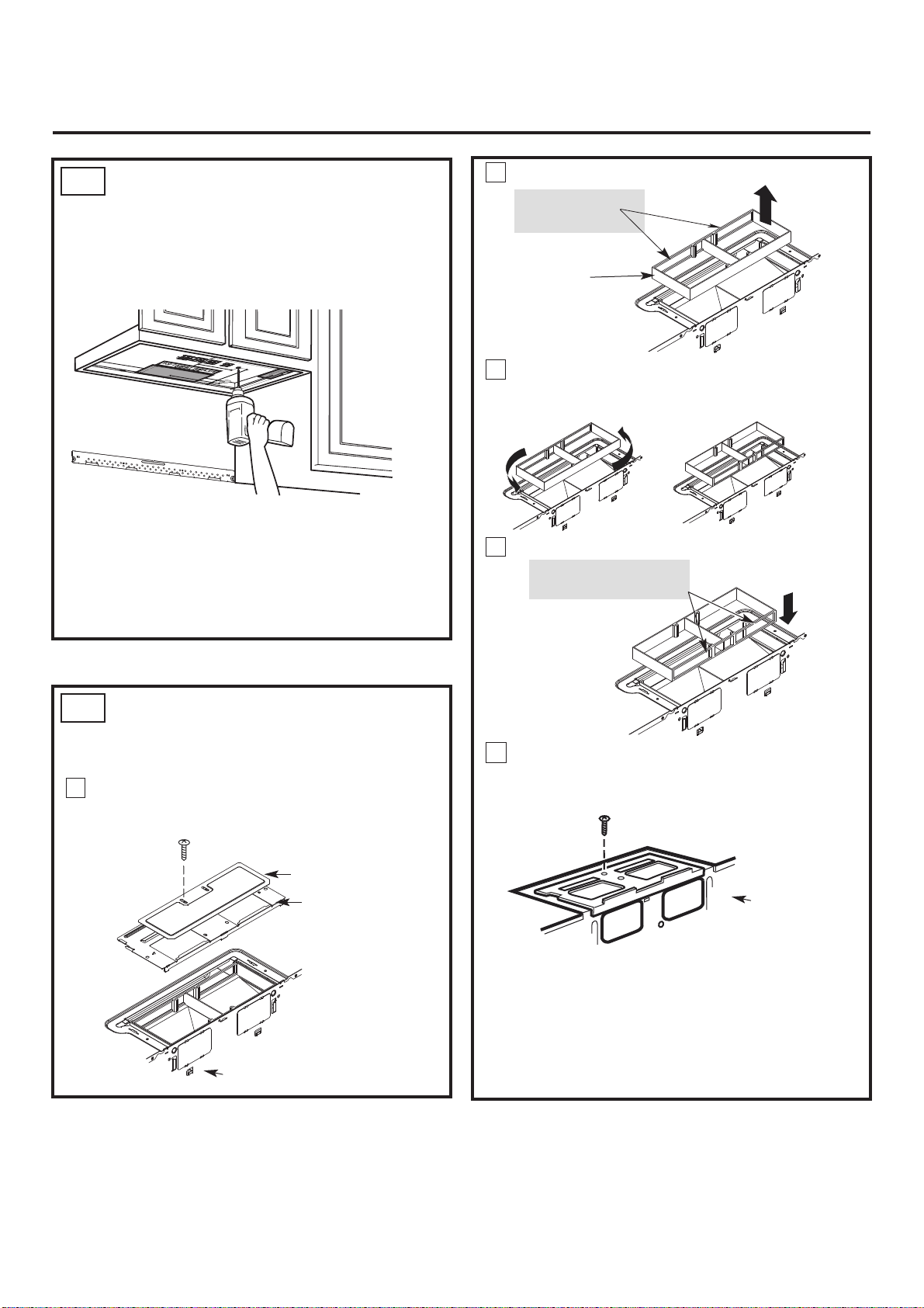
Installation Instructions
C2.
USE TOP CABINET TEMPLATE
FOR PREPARATION OF TOP
CABINET
You need to drill holes for the top support
screws and a hole large enough for the power
cord to fit through.
• Read the instructions on the TOP CABINET
TEMPLATE.
• Tape it underneath the top cabinet.
• Drill the holes, following the instructions on
the TOP CABINET TEMPLATE.
CAUTION:Wear safety goggles when drilling
holes in the cabinet bottom.
Carefully pull out the air director.
2
Before:
Openings Facing
Forward
Air Director
Rotate the air director counterclockwise 180°
3
Before Rotation After Rotation
Place the air director back into the opening.
4
AFTER: Air Director
Openings Facing Back
C3.
ADAPTING MICROWAVE AIR
DIRECTOR FOR OUTSIDE
BACK EXHAUST
Remove the screw that holds the blower
1
plate to the microwave. Remove the cover
plate.
Cover Plate
Blower Plate
Back of
Microwave
5
Replace blower plate with the screw
removed in Step 1. Make sure the screw is
tight.
Back of
Microwave
EN-20
Page 22
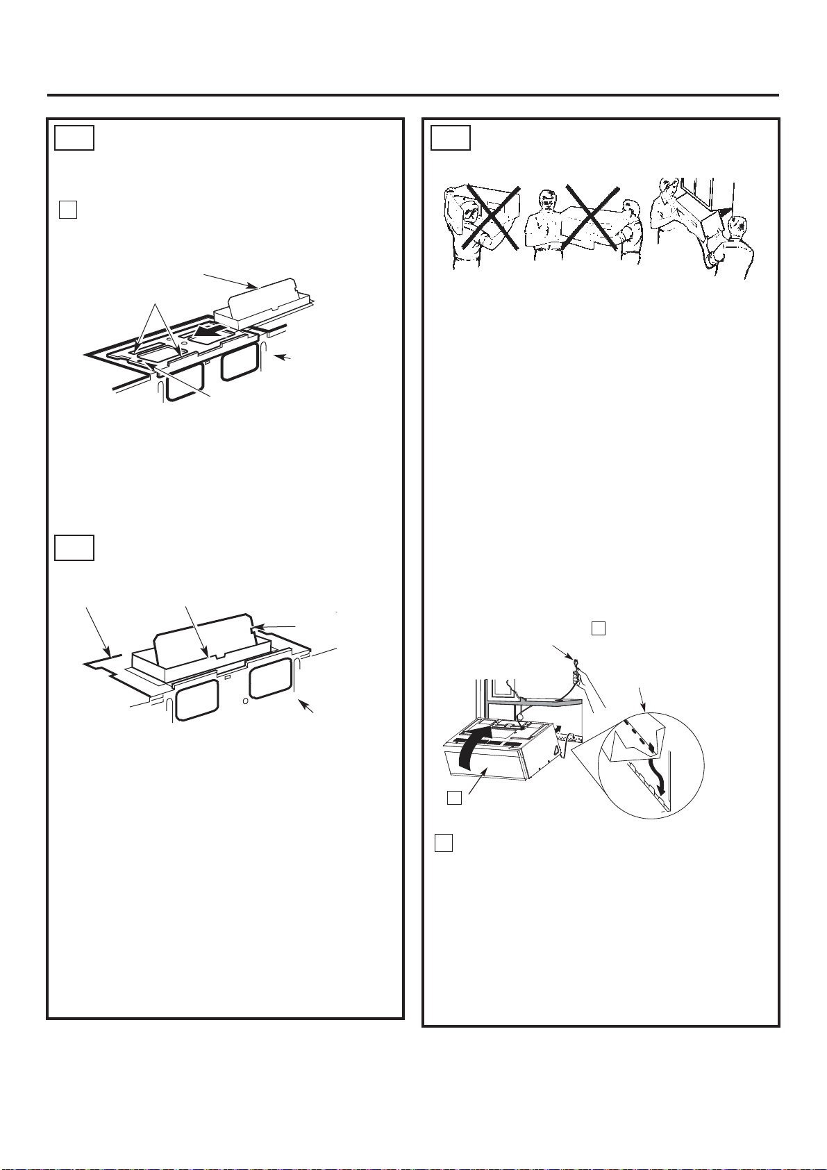
Installation Instructions
C3.
ADAPTING MICROWAVE
BLOWER FOR OUTSIDE
BACK EXHAUST (cont.)
6
Attach the exhaust adaptor to the top of
the blower plate by sliding it into the guides
of the blower plate.
Adaptor
Guide
Back of
Microwave
Locking Tab
Push in securely until it is in the lower locking
tabs. Take care to assure that the damper
hinge is installed so that it is at the top and
that the damper swings freely.
C3.
CHECK FOR PROPER
DAMPER OPERATION
Blower Plate
Exhaust Adaptor
Damper
C5.
MOUNT THE MICROWAVE
OVEN
FOR EASIER INSTALLATION AND PERSONAL
SAFETY, WE RECOMMEND THAT TWO
PEOPLE INSTALL THIS MICROWAVE OVEN.
IMPORTANT: Do not grip or use the handle or
heat shield during installation. Do not remove
the cardboard spacers between the heat
shield and door.
NOTE: If your cabinet is metal, use the nylon
grommet around the power cord hole to
prevent cutting of the cord.
NOTE: We recommend using filler blocks if
the cabinet front hangs below the cabinet
bottom shelf.
IMPORTANT: If filler blocks are not used,
case damage may occur from overtightening
screws.
NOTE: When mounting the
microwave oven, thread
power cord through hole in
bottom of top cabinet. Keep
it tight throughout Steps 1–3.
Do not pinch cord or lift
oven by pulling cord.
Lift microwave, tilt it
1
forward, and hook slots at
back bottom edge onto four
lower tabs of mounting
plate.
Back of
Microwave
• Make sure tape securing damper is removed
and damper pivots easily before mounting
microwave.
• You will need to make adjustments to assure
proper alignment with your house exhaust
duct after the microwave is installed.
EN-21
2
Rotate front of oven
up against cabinet
bottom.
Insert a self-aligning screw through top
3
center cabinet hole. Temporarily secure the
oven by turning the screw at least two full
turnsa fter the threads have engaged. (It
will be completely tightened later.) Be sure
to keep power cord tight. Be careful not to
pinch the cord, especially when mounting
flush to bottom of cabinet.
Page 23
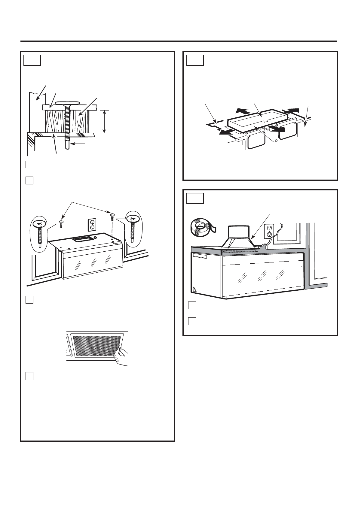
Installation Instructions
C5.
MOUNT THE MICROWAVE
OVEN
Cabinet Front
Cabinet Bottom Shelf
Filler Block
Equivalent to Depth
of Cabinet Recess
Self-Aligning Screw
Microwave Oven Top
Attach the microwave oven to the top
4
cabinet.
5
Insert 2 self-aligning screws through outer
top cabinet holes. Turn two full turns on
each screw.
C6.
ADJUST THE EXHAUST
ADAPTOR
Open the top cabinet and adjust the exhaust
adaptor to connect to the house duct.
Blower Plate
C7.
CONNECTING DUCTWORK
Damper
For Front-to-Back or
Side-to-Side Adjustment,
Slide the Exhaust Adaptor
as Needed
House Duct
Back of
Microwave
6
Tighten the outer two screws to the top
of the microwave oven. (While tightening
screws, hold the microwave oven in place
against the wall and the top cabinet.)
7
Install grease filters. See the Use & C are
manual packed with the microwave.
IMPORTANT: Remove the cardhoard spacers
between heat shield and door.
Extend the house duct down to connect to
1
the exhaust adaptor.
Seal exhaust duct joints using furnance duct
2
tape for high temperature applications.
EN-22
Page 24
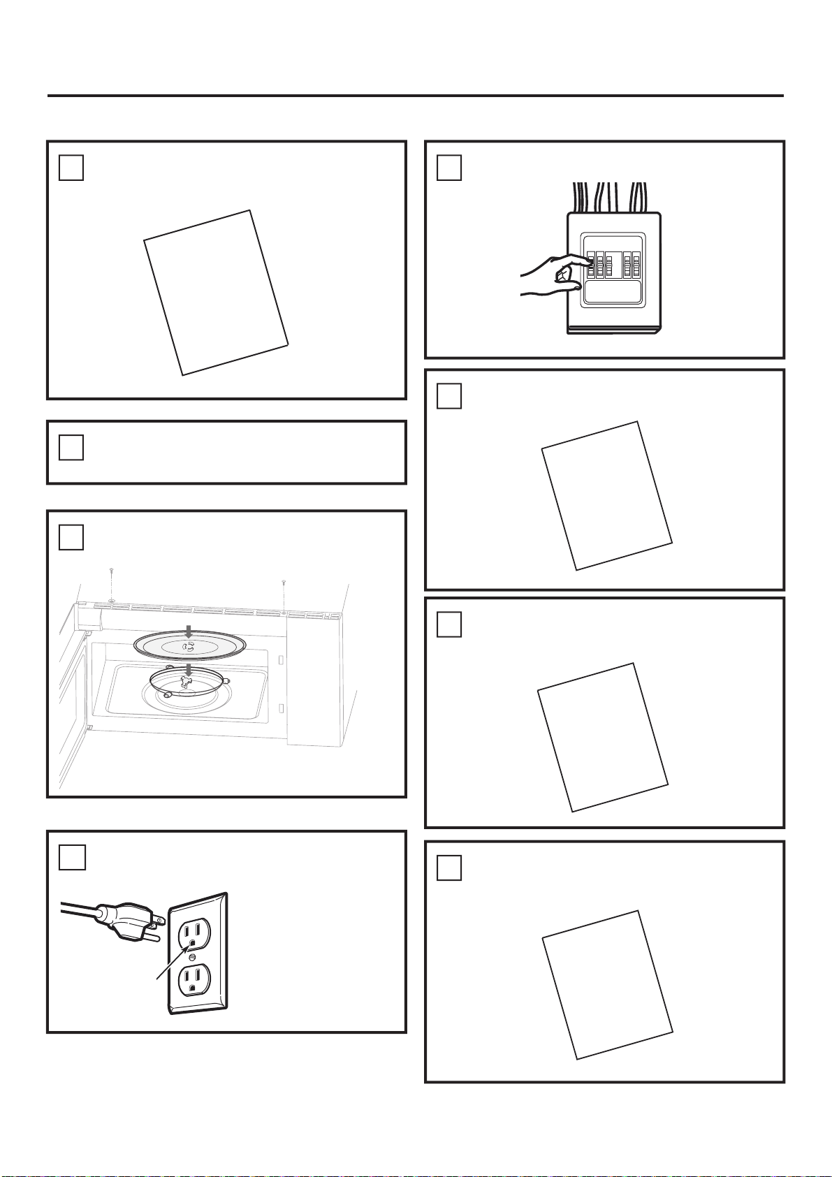
Installation Instructions
INSTALLATION
INSTRUCTIONS
MANUAL
BEFORE YOU USE YOUR MICROWAVE
1.
Make sure the microwave oven has been
installed according to instructions.
2.
Remove all packing material from the
microwave oven.
3.
Install turntable ring a nd glas s tra y i n
cavity.
5.
Replace house fuse or turn breaker back on.
6.
Read the USE&CARE Manual.
CARE
&
USE
4.
Plug power cord into a seperate and
dedicated 15- to 20-amp electrical outlet.
Ensure proper
ground exists
before use
7.
KEEP INSTALLATION INSTRUCTIONS FOR
THE LOCAL INSPECTOR’S USE.
INSTALLATION
INSTRUCTIONS
8.
FILL OUT PRODUCT REGISTRATION CARD
AN SEND IN.
PRODUCT
REGISTRATION
CARD
EN-23
Page 25
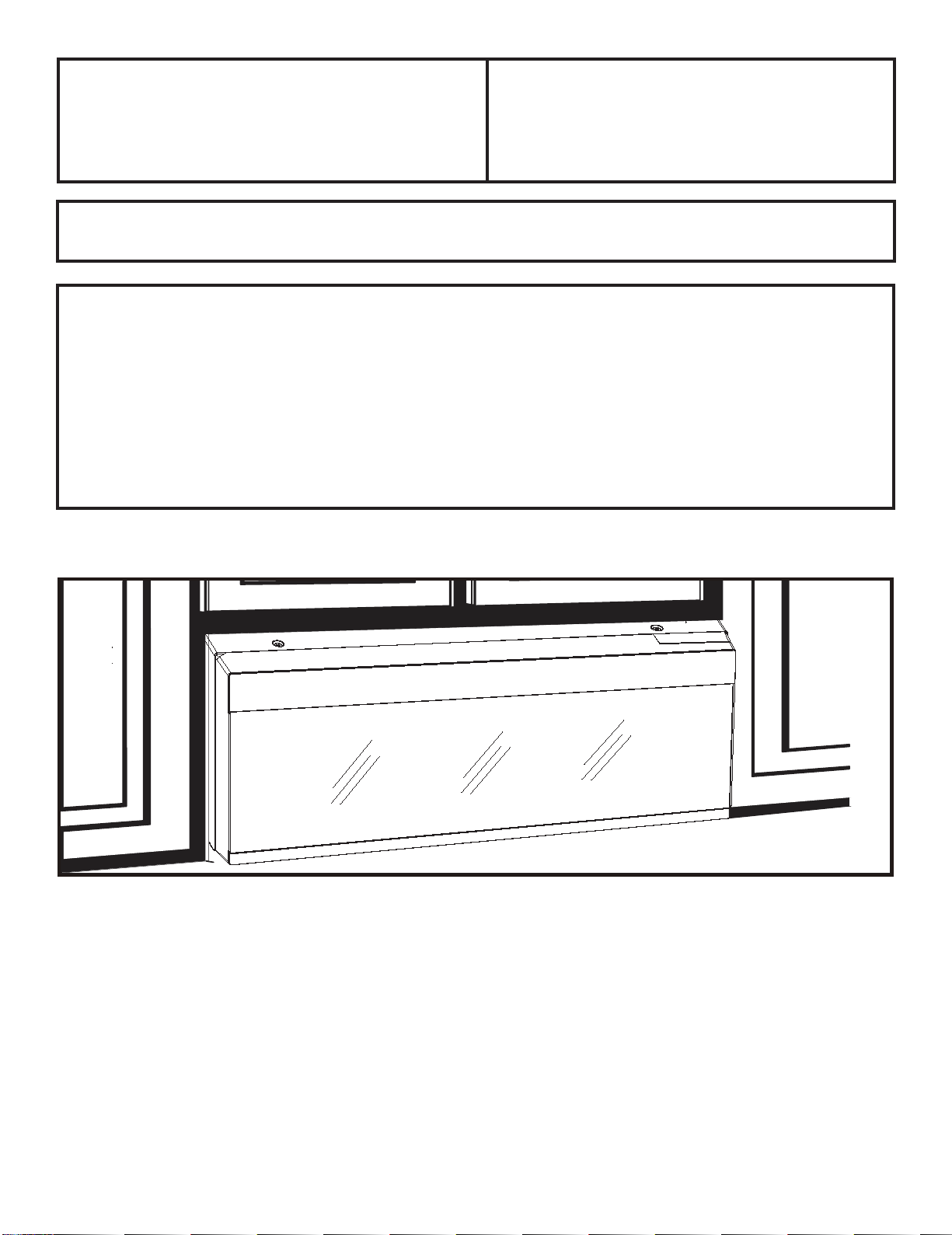
Instrucciones de
Horno microondas
instalación
¿Preguntas? Llame al 1-800-944-9044(US) o 1-800-265-8352(Canada)
(encima de la estufa)
ANTES DE EMPEZAR
Lea estas instrucciones completamente y con atención.
IMPORTANTE: conserve estas instrucciones
•
para uso futuro del inspector local.
•
IMPORTANTE: asegúrese de que se cumplan
todas las normas y los códigos relevantes.
• Nota para el instalador: asegúrese de dejar
estas instrucciones en manos del consumidor.
•
Nota para el consumidor: conserve estas
instrucciones para referencia futura.
• Nivel de preparation tecnica: la instalacion de este
electrodomestico requiere conocimientos
mecánicos y eléctricos básicos.
• La instalacion correcta es responsabilidad del instalador.
• Las fallas del producto que resulten de una
instalación incorrecta no están cubiertas bajo la
garantía.
LEA CUIDADOSAMENTE.
CONSERVE ESTAS INSTRUCCIONES.
p/n A06823451
Agosto 2022
Page 26

Page 27
Instrucciones de instalación
CONTENIDO
Información general
Instrucciones importantes sobre seguridad.......3
Requisitos eléctricos................................................ 3
Daños-envío (transporte)/instalación ................. 4
Piezas incluidas ......................................................... 4
Herramientas necesarias.........................................5
Espacio para la instalación.....................................5
Guía de la instalación paso a paso
Colocación de la placa de instalación ..............6-8
Desintalación la placa de instalación ................6
Localización de las vigas de la pared ..............6
Extracción superior externa................19-22
C
Montaje de instalación la placa de en la
pared......................................................................19
Preparación del gabinete superior..............20
Ajuste del ventilador del microondas para
la extracción superior externa................20-21
Verificación del funcionamiento correcto
del regulador de extracción...........................21
Instalación del horno microondas........21-22
Ajuste del adaptador de extracción..........22
Acoplamiento del sistema de
conductos..............................................................22
Antes de usar el horno microondas..........22
La información de plantilla..................................23
Ubicación de la placa para la pared ..................7
Alineación de la placa para la pared.................8
Tipos de instalación ................................................. 9
Recirculación ............................................ 10-12
A
Montaje de la placa de instalación en la
pared... ................................................................10
Preparación del gabinete superior............11
Verificación del conjunto del placa del
ventilador pared...............................................11
Instalación del horno microondas.......11-12
Instalación o cambiar del filtro de carbón..12
Campana extractora..........................................13-14
Extracción trasera externa...................15-18
B
Preparación de la pared trasera para la
salida de extracción trasera externa..........15
Desinstalación del placa del ventilador....15
Montaje de la placa de instalación en la
pared.....................................................................16
Preparación del gabinete superior.............16
Ajuste del ventilador del microondas para
la extracción superior externa................16-17
Instalación del horno microondas..............18
ES-2
Page 28
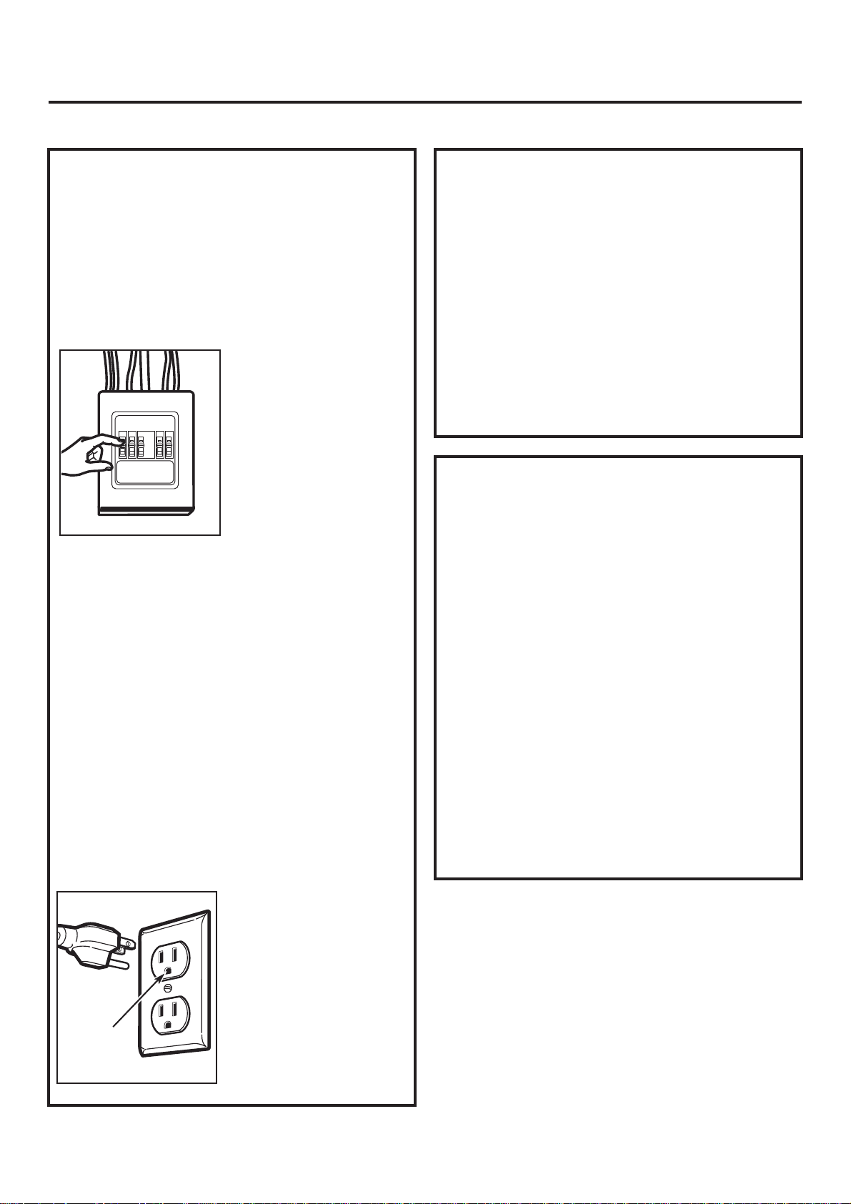
Instrucciones de instalación
INSTRUCCIONES IMPORTANTES SOBRE SEGURIDAD
Este product require un tomacorriente de tres
clavijas con puesta a tierra. Antes de proceder con
la instalación del electrodoméstico, el instalador
debe realizar una verificación de la continuidad de
la puesta a tierra del tomacorriente, a fin de
asegurarse de que es correcta. Si la puesta a tierra
no es correcta o si el tomacorriente no cumple con
los requisites eléctricos descritos en este manual
(en la sección REQUISITOS ELÉCTRICOS), se deberá
solicitor a un eléctricista calificado que corrija
cualquier defecto detectado.
PRECAUCIÓN: por
razones de seguridad
personal, antes de
comenzar con el
procedimiento de
instalación, retire el
fusible correspondiente o
desconecte el disyuntor
doméstico, a fin de evitar
cualquier lesion personal
causada por un choque
eléctric.
PRECAUCIÓN: por razones de seguridad personal,
la superficie de instalación debe ser capaz de
soportar la carga del gabinete, además del peso
adicional del product (63 a 85 libras o 28,5 a
38,5kg), así como cargas adicionales de hasta 50
libras (22,7kg), o bien un peso total de 113 a 135
libras (51,3 a 61,2kg).
PRECAUCIÓN: por razones de seguridad personal,
este product no puede ser instalado en espacios
de gabinete tipo insular o peninsular. Debe ser
atornillado (instalado)
TANTO al gabinete superior, COMO a la pared.
NOTA: por razones de seguridad personal y para
facilitar la instalación, se recomienda que dos
personas instalen el product.
IMPORTANTE: ¡LEA CUIDADOSAMENTE! POR
RAZONES DE SEGURIDAD PERSONAL, EL
ELECTRODOMÉSTICO DEBE QUEDAR
DEBIDAMENTE PUESTO A TIERRA, PARA EVITAR
CUALQUIER CHOQUE ELÉCTRICO QUE PUEDA
CAUSAR LA MUERTE.
Se debe solicitor a un eléctricista calificado que
inspeccione el tomacorriente de pared y el circuito
eléctrico correspondiente, a fin de asegurarse de
que el tomacorriente esté
debidamente puesto a tierra.
En caso de que el tomacorriente estándar
disponible sea solamente para un enchufe de dos
clavijas, es muy importante solicitor a un
eléctricista calificado que lo reemplace con un
tomacorriente de tres clavijas puesto a tierra.
BAJO NINGUNA CIRCUNSTANCIA CORTE,
ALTERE O ELIMINE LA TERCERA CLAVIJA
(TIERRA) DEL CABLE ELÉCTRICO.
NO USE UN CABLE ELÉCTRICO DE EXTENSIÓN.
REQUISITOS
ELÉCTRICOS
La potencia nominal del product es de 120 voltios
de CA, 60 Hertz, 15 amperios y 1,6 kilovatios. Debe
ser conectado a un circuito separado y dedicado de
alimentación eléctrica que tenga el voltaje y la
frecuencia adecuados.
El diámetro del alambre debe cumplir con los
requisitos
correspondientes del código eléctrico nacional
(National Eléctrical Code O NEC) de los EE.UU., o
bien con las normas vigentes locales
correspondientes a la potencia nominal en
kilovatios del apparato. El cable y el enchufe de
alimentación eléctrica deben ser conectados a un
tomacorriente (con puesta a tierra) de un circuito
separado y dedicado de 15 a 20 amperios. El
tomacorriente
debe estar situado en el espacio superior del
gabinete en el cual se instalará el microondas. El
tomacorriente y el circuito de alimentación eléctrica
deben ser instalados por un eléctricista calificado y
deben cumplir con el código NEC de los EE.UU. o
con las normas vigentes locales correspondientes.
Antes de usar el
electrodoméstico,
verifique la
puesta a tierra del
tomacorriente.
El cable de alimentación
de este product está de
este product está
equipado con un enchufe
(con puesta a tierra) de 3
clavijas, compatible con
un tomacorriente de
pared (con puesta a
tierra) de 3 clavijas, lo
cual minimize la
posibilidad de choque
eléctric causado por el
producto.
ES-3
Page 29
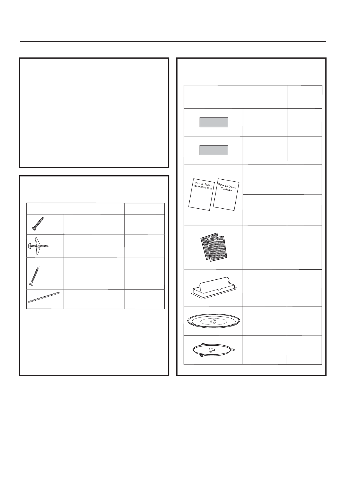
Instrucciones de instalación
DAÑOS-ENVÍO
(TRANSPORTE)/INSTALACIÓN
• Si el producto ha resultado dañado durante su
envío (transporte), devuélvalo a la tienda/el
almacén donde to adquirió, para que lo reparen o
lo cambien por uno nuevo.
• Si el producto ha sido dañado por el comprador, la
reparación o el reemplazo del producto es
responsabilidad del comprador.
• Si el instalador (no el comprador) daña el
producto, la reparación o el reemplazo del mismo
tendrá que ser acordado entre el comprador y el
instalador.
PIEZAS INCLUIDAS
KIT DE FERRETERÍA
PIEZA CANTIDAD
PIEZAS INCLUIDAS
KIT DE FERRETERÍA
PIEZA CANTIDAD
Tornillos para madera
(1/4 " x 2")
2
Plantilla para el
gabinete
superior
Plantilla para la
pared trasera
combinado
Instrucciones
de instalacion
Guia de Uso y
Cuidado
(CONT.)
1
1
1
1
Tornillos de fiador
(y tuercas de
mariposa) ( 3/16" x 3")
Tornillos autoalinea
-ntes para máquina
(1/4 "-28 x3
Moldura aislante de
nylon (para los
gabinetes metálicos)
Las piezas de ferretería vienen dentro de un
paquete (kit) incluido con el
electrodoméstico. Verifique que el paquete
contiene todas las piezas listadas aquí.
NOTA: se incluyen algunas piezas adicionales.
1/4")
2
3
1
Filtros de grasa
(empacados
por separado)
Adaptador
Bandeja de
vidrio
Anillo de la
bandeja
giratoria
2
1
1
1
ES-4
Page 30
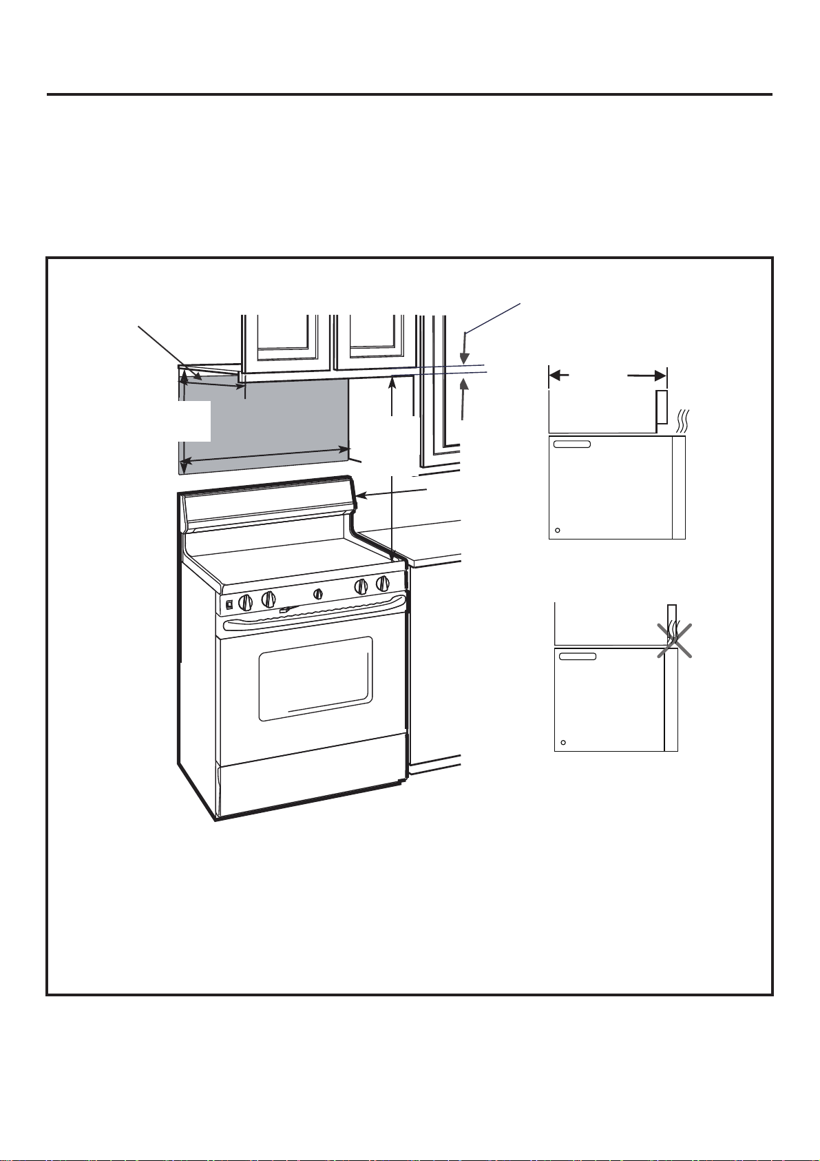
Instrucciones de instalación
Herramientas necesarias:
• Mètre
• scie trépan
• Trouveur de goujons ou
marteau
• Niveau
• Ruban adhésif et de masquage
• Ciseaux
Espacio para la instalación
13.8" Max
(35 cm)
10.3
"
(26.2cm)
30
"(7
6.
2c m
• n #1 tournevis cruciforme
• Perceuse électrique
• Foret 3/16 ’’, 1/2 ’’, 5/8 ’’
• Blocs de bois de remplissage pour armoires
à fond encastré
• Cisailles
¼" Min
espacio libre
13.8" MAX.
(35 cm)
"
)
24
(61cm)
min.
Protector contra
salpicaduras
Gabinete
Gabinete
• El espacio entre los gabinetes debe ser de 30" (76,2 cm) de ancho v libre de obstrucciones.
• Si la extracción de aire para el horno microondas será dirigida hacia fuera de la cocina, consulte la sección
sobre campana extractora, para informarse sobre la preparación del conducto de extracción.
• Si va a instalar el horno microondas debajo de un gabinete plano y liso, tenga cuidado de seguir las
instrucciones sobre la plantilla para el gabinete superior, especialmente la parte relacionada con el espacio
libre para el cable eléctrico.
• Como el gua de la instalacin, se vea el pgina 26 por la informacin de plantilla montada.
• Si la profundidad del gabinete incluyendo las puertas es mayor de 13,8 entonces la unidad debe alejarse de
la pared con materiales adecuados que soporten 150 lbs para permitir una ventilación adecuada/toma de
aire.
ES-5
Page 31
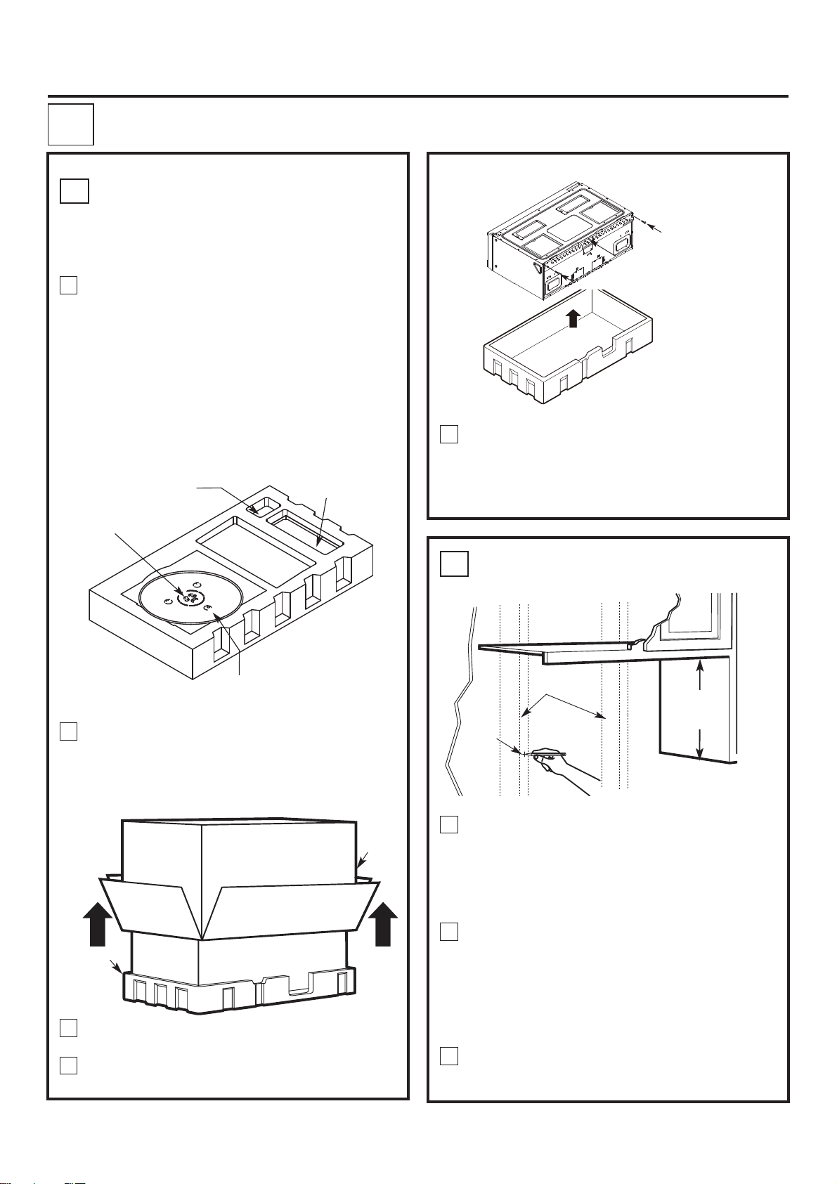
Instrucciones de instalación
COLOCACIÓN DE LA PLACA DE INSTALACIÓN
1
PROCEDIMIENTO PARA
A
.
SACAR DE LA CAJA EL
MICROONDAS Y LA PLACA DE
INSTALACIÓN
Retirar las instrucciones de instalación, uso y
1
cuidado, adaptador de escape, anillo giratorio,
estante, filtros, bandeja de vidrio y bolsa de
accesorios pequeña. No retire el poliestireno
de la parte delantera del horno.
Mantenga la unidad a una distancia mínima de
8 pulgadas del borde de la encimera para
evitar que se caiga debido al peso de la
puerta.
Bolsa de accesorios
pequeña
Filtros y anillo giratorio
debajo de la bandeja
de vidrio
Adaptador de
escape
Placa de instalación
Tornillos
Quite los tornillos de la placa de instalación.
5
Dicha placa se utilizará como plantilla para la
pared trasera y para la instalación. Vuelva a
insertar los tornillos en los agujeros de los
cuales habían sido extraídos.
Tornillos
Bandeja de vidrio
Doble hacia atrás las 4 lengüetas de la caja de
2
cartón, para que queden contra los lados de la
caja. A continu- ación, dé la vuelta con cuidado
al horno y la caja, para que la caja quede en la
parte superior. El horno quedará colocado sobre
el protector de espuma.
Espuma
de
poliestire
no
Tire de la caja de cartón hacia arriba, para
3
separarla del horno.
Come la bolsa de plástico en el medio para
4
retirar la placa de instalación.
Caja de
cartón
LOCALIZACIÓN DE LAS VIGAS
B.
DE LA PARED
Vigas de
la pared
(26.2cm)
Centro
Localice las vigas mediante cualquiera de los
1
métodos siguientes:
A. Detector de vigas. aparato magnético que detecta clavos.
B. Use un martillo para dar golpecitos leves sobre
la superficie de instalación, a fin de detectar el
sonido de superficie maciza (no hueca). Esto
indicará la ubicación de una viga.
Tras localizar la(s) viga(s), localice su centro
2
haciendo pruebas en la pared con un pequeño
clavo que le permita detectar los bordes de la
viga. A continuación, haga una marca que quede
a la mitad de ambos bordes.
El centro de cualquier viga adyacente debe quedar a
16" (40,6 cm) o 24" (61 cm) de dicha marca.
Trace una línea hacia abajo del centro de las vigas.
Trace una línea hacia abajo del centro de las vigas.
3
EL MICROONDAS DEBE QUEDAR ATORNILLADO
AL MENOS A UNA VIGA DE LA PARED
ES-6
10.3
"
Page 32
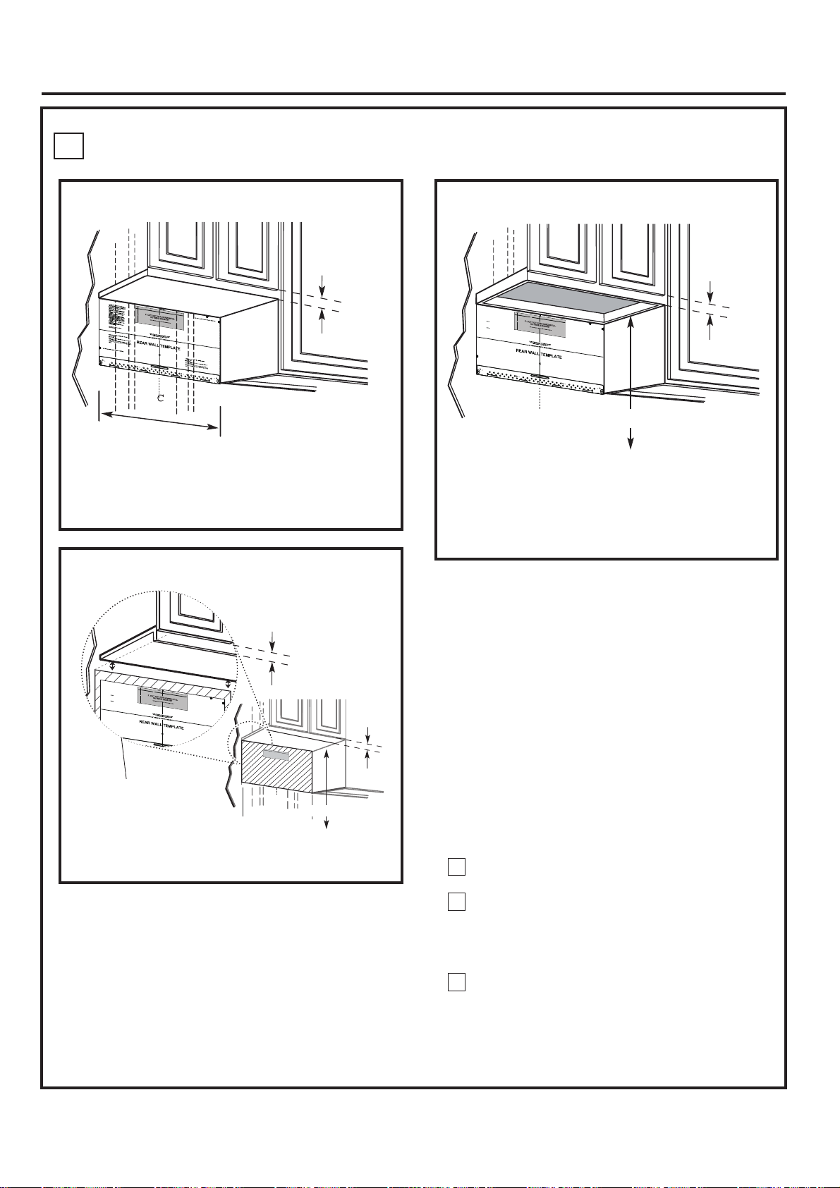
Instrucciones de instalación
3
/8"
TO
E
D
G
E
N
O
TE:
I
T
IS
VE
R
Y
I
MP
OR
T
A
N
T
T
O
REA
D
A
N
D
F
O
L
LOW
TH
E
D
IRECTIONS
I
N
T
H
E
IN
S
T
A
LL
A
T
IO
N
IN
S
TR
U
CT
I
O
N
S
B
E
FO
RE P
R
O
CEED
I
NG
W
I
T
H
T
H
I
S
R
E
A
R WA
L
L
T
E
MP
L
AT
E.
This
R
e
ar
W
all Tem
p
la
t
e s
er
v
e
s
to p
os
it
i
o
n
the
b
o
t
to
m
mo
u
nting
pla
te
a
n
d
to l
o
c
at
e
th
e ho
riz
on
ta
l e
xha
ust
outle
t.
1
. U
s
e a
l
ev
el
to
c
heck
th
at
th
e
te
mp
la
t
e is
p
o
sit
i
o
ne
d
a
c
c
u
r
at
e
ly
.
2
.
Loca
te
and
ma
r
k
a
t le
a
s
t
o
n
e st
u
d
o
n t
he
left
o
r
r
i
g
ht
s
id
e
o
f
th
e c
e
nte
r
l
ine.
It is
i
mpo
rtan
t t
o
us
e a
t le
a
s
t
o
n
e
w
ood
s
c
r
e
w
mo
un
t
ed firmly in
a
s
tu
d
t
o
su
ppo
rt the
w
e
ig
h
t
o
f
th
e
micr
ow
av
e
.
Ma
rk t
w
o
a
dditio
nal,
e
v
enly
s
p
ace
d
loc
a
tion
s fo
r
the
s
upp
l
i
ed t
og
gle bol
ts.
3. D
r
ill holes in
t
he ma
rke
d
lo
c
ation
s. Whe
re th
er
e is
a
stud
, d
rill
a 3
/1
6
"
h
o
le
fo
r w
o
od
s
c
rews
.
For
h
oles
t
h
a
t do n
ot line
up
with a s
tud
,
d
r
ill
5
/8
" h
o
les fo
r
toggle
bo
lts.
D
O N
OT INS
TAL
L
TH
E
MO
U
N
TIN
G PL
ATE
AT TH
I
S TI
M
E
.
4.
Re
m
ov
e
the
te
mpla
te
fr
om t
he
rea
r
w
all.
5
.
Re
v
ie
w
t
he
In
s
t
allatio
n
In
s
tru
c
t
io
n
bo
o
k fo
r
y
ou
r
in
sta
llatio
n
s
itu
a
tio
n.
L
o
ca
t
e an
d
ma
r
k
h
o
l
e
s
to a
l
ig
n
w
it
h
h
ol
e
s
i
n
th
e
mo
u
n
t
i
ng
p
la
t
e.
IM
P
OR
T
A
N
T
:
LO
C
AT
E
AT
LE
A
S
T
ON
E
S
T
U
D
O
N
E
I
TH
E
R
SI
DE
OF
TH
E
C
E
NTE
RL
I
NE.
M
AR
K T
HE L
OC
A
TI
O
N
FO
R
2
A
D
D
I
T
I
ON
A
L
,
E
VEN
L
Y
SP
A
C
ED
TOGGLE
B
O
L
T
S
I
N
T
H
E
M
O
UNT
I
N
G
PL
AT
E
AR
E
A.
Lo
cate
a
n
d
mar
k
h
o
l
e
s
t
o
a
l
i
gn
w
i
t
h
h
ol
e
s
in
t
he
m
o
untin
g
pl
a
t
e
.
I
M
PO
R
T
A
NT:
L
OC
A
TE
A
T
L
E
A
S
T
ON
E ST
U
D
O
N
EI
T
H
ER
S
IDE
O
F
T
H
E
C
E
N
T
E
R
LI
NE
.
M
AR
K
T
HE
LOCA
TI
O
N
F
O
R
2
A
D
D
IT
IONAL
,
EVEN
LY
S
PA
C
E
D
T
O
G
GL
E
BOL
T
S
I
N
T
H
E
M
O
UN
T
A
R
EA
.
Tri
m
t
he
r
ea
r
wa
ll
t
empl
at
e
a
l
ong
th
e
do
t
ted
lin
e
.
T
r
i
m
t
h
e
r
ea
r
w
al
l
te
m
pl
a
t
e
a
l
o
n
g
the
do
tted
li
n
e.
12
"
4"
D
a
rl
e
v
ue
l
t
a
a
l
a
ho
ja
para
co
n
s
u
l
t
ar
l
a
ve
rsi
n
e
n
E
s
paæ
o
l
.
C.
UBICACIÓN DE LA PLACA PARA LA PARED DE BAJO DEL GABINETE
Posición de la placa-debajo de la superficie
plana inferior del gabinete
1/4"
min espacio
libre
Al menos 30"
Dibuja una línea vertical en la pared en el centro
del espacio cuyo ancho es 30".
Cinta la Plantilla de pared posterior en la pared
correspondiente a la línea y toca el fondo del
armario.
Posición de la placa-debajo de la superficie hueca
saliente, delantera e inferior (con marco) del
gabinete
1/4"
min espacio
libre
1/4"
overhang
Trace una línea en el
fundo de la pared
igal a la profundidad
del voladizo
delantero
N
OT
E
: I
T
IS
V
R
ER
E
A
Y
D
I
MP
A
ND
O
F
RT
O
IN
AN
LL
TH
T T
O
E I
W
O
T
N
HE
S
T
A
D
B
L
E
IR
L
FO
AT
E
C
R
I
O
TI
E P
N
O
I
N
R
N
S
O
STR
R
CE
E
A
U
E
R
C
D
W
T
I
N
I
A
O
G
LL
N
W
S
Th
T
IT
is
E
H
M
R
e
PL
T
ar
H
W
A
3
IS
/8
al
TE.
"
l
Te
m
TO
o
m
u
E
n
p
DG
tin
l
at
E
g
e
plat
se
r
e
v
e
o
an
s
u
tl
to
d
et.
t
p
o
o
lo
sit
12"
c
i
a
o
t
n
e
t
t
h
he
1.
e
b
Use
h
o
o
t
r
t
o
i
zo
a
m
n
l
ev
ta
l
e
e
l
xh
t
o
a
c
a
u
he
c
s
cu
t
c
k
r
t
a
h
te
a
l
t
y.
t
h
e
2
t
.
e
L
mpla
oc
a
t
te
e
an
i
s
d
p
o
m
s
ar
it
i
rig
k a
on
h
e
t
t
d
l
s
e
i
d
a
s
e
t
of
o
n
t
e
h
e
st
c
u
e
d
nte
o
n
r
l
t
i
h
n
I
e
e
t
4
.
is
le
"
f
im
t
o
p
r
s
o
c
rt
re
a
w
nt
m
t
o
ounted
u
s
e
a
o
t
f
f th
l
i
e
r
m
a
e
s
l
y
t
mi
o
i
n
n
c
a
e
r
ow
stu
w
oo
a
d
v
l
d
o
e.
t
o
c
a
M
s
t
u
io
ark
pp
ns fo
o
t
w
r
t
o
r
the
t
a
h
d
e
3
w
d
.
s
iti
e
u
D
i
o
ppli
g
r
n
ill
h
a
t
h
l
e
,
o
d
e
l
v
es
t
o
e
g
n
in
gle
ly
t
s
he
b
pa
a
ol
m
st
ce
t
s
ark
u
d
.
d
, d
e
d
ri
l
l
l
a
3
/
that
1
d
o
n
o
t
li
ne
t
u
o
gg
le
bol
ts
.
D
O
NOT
A
T
I
N
T
H
I
S
T
IM
E
.
4.
R
e
m
o
v
e
t
h
e
t
5
e
. R
m
e
v
i
e
w t
he
Ins
i
tal
n
s
t
a
lla
t
i
o
n
s
i
t
u
a
t
Da
r
le
v
ue
l
t
a a
v
l
a
e
r
h
s
i
n
en
E
sp
a
æ
L
o
cat
e
a
n
d
m
ar
m
o
u
n
t
i
n
g
p
l
a
t
I
MPO
R
T
A
NT
:
L
O
CA
T
E
A
T
L
T
H
E
C
E
N
T
E
R
M
A
R
K
T
HE
L
O
SP
A
C
E
D
TO
G
ARE
A
.
Tr
im
th
e
r
ear
w
a
l
l
t
e
m
p
l
at
e
Tr
oc
a
im
t
i
o
ns
6
"
ho
l
e
f
or
p
w
i
t
h
a
s
t
ud
S
TA
LL
T
H
p
la
te
f
r
o
m
t
la
t
io
n
Ins
t
ru
i
o
n
.
o
j
a
p
a
r
a c
o
l.
k
h
o
l
e
e
.
E
A
S
T
ON
LI
N
E.
C
A
T
IO
GL
E
B
OL
al
o
n
g
t
h
th
.
W
e
he
r
re
ea
t
w
h
o
od
s
,
dr
i
ll
E
MO
h
e
r
e
a
c
t
io
n b
o
n
s
u
s
t
o
a
E
S
N
F
O
T
S
e
d
o
r
e
w
re
al
is
c
re
ws
.
5
/8
"
h
UNT
IN
r wa
l
l.
oo
k
f
o
lta
r
la
li
g
n wit
T
U
D ON
R
2
I
N
T
t
t
e
d
l
te
F
or
h
o
le
s
fo
G P
L
ATE
r
y
o
ur
h
h
A
D
D
H
E
M
l
i
ne.
mp
l
a
o
le
s
r
ole
s
i
E
I
T
H
E
IT
I
O
N
OUNTING
t
e
alo
n
g
t
h
e
d
o
t
t
e
d
l
i
n
e
n
t
he
R
S
IDE
O
F
A
L,
E
VE
NL
Y
P
L
A
T
E
.
Lo
c
ate
a
n
d
ma
r
k
moun
h
o
l
es
ti
n
t
o
g
a
p
lign
l
at
e
.
w
i
IM
th h
PO
o
l
RTA
es
i
n
N
t
T
h
:
e
LO
C
A
T
E
AT
L
EA
T
ST
H
E
O
C
N
E
E
NT
S
ER
T
U
D
L
I
ON
NE
MA
.
R
E
K
I
TH
T
H
E
E
R
L
SIDE OF
OC
S
A
P
TI
AC
O
N
E
F
D
O
T
R
O
G
2
G
A
A
L
D
E
R
D
E
I
BO
TIO
A
.
L
T
NA
S
L
IN
,
E
T
V
H
ENL
E M
Y
O
U
N
T
I
N
G
P
LAT
E
C
24" a la superficie de cocción
min espacio
libre
Posición de la place-debajo de la superficie
hueca inferior (con marco) del gabinete
1/4"
min espacio
libre
NOT
E
:
I
T
IS
V
E
RE
R
Y
A
D
I
MP
A
N
O
D
R
F
T
O
A
IN
N
LLO
T
THE
T
W
O
T
I
N
HE
STA
DI
L
BE
RE
L
A
F
CT
TI
OR
ON
I
ONS
E
I
P
N
R
S
O
T
R
CEED
RUC
E
AR
T
I
I
W
N
ON
G
A
L
S
W
L
IT
T
E
T
MP
h
i
s
R
LA
e
a
TE
r
Wa
.
l
l
T
mo
e
mp
un
l
t
at
i
n
e
g
s
p
e
l
a
r
ve
t
e
s
a
o
n
t
ut
o
d
l
p
et
t
o
o
.
si
l
o
t
c
at
e
t
h
e
1
h
.
or
Use
i
z
o
n
a lev
e
l
t
o
ch
a
e
c
ck t
c
ur
h
a
at
t
el
t
y.
h
e
t
e
2
m
.
L
p
oc
la
te
a
te
a
n
d
m
a
r
k
r
i
g
a
h
t l
t
e
s
a
i
de
st
o
o
n
f
e
th
s
e
t
ud
c
ente
o
n t
r
l
in
e
I
.
t
is
i
mp
o
sc
r
ta
re
nt
w
t
m
o u
ou
se
n
t
ed
a
t
lea
f
o
i
r
f
ml
s
the
t
y
o
i
n
m
n
i
a
cr
s
o
t
w
u
d
a
to
v
e
l
o
.
s
cati
M
u
p
a
o
p
rk
o
n
s
tw
fo
o
r
a
t
d
h
d
e
i
3
t
su
i
.
on
Dr
ppl
al
i
ll
,
i
ed
e
h
ol
t
e
o
s
g
g
in
le
t
he
bol
a
m
t
s
s
.
ar
t
u
ke
d
,
d
d
lo
r
i
ll
ca
a
t
3/
io
1
n
t
6
s. Wh
h
"
a
t
h
d
o
o
l
e
n
f
o
o
r
t
l
w
in
o
e
to
o
u
d
p
scr
g
w
g
i
l
e
t
e
h
bo
a
s
lt
t
s
u
.
d
,
d
r
i
l
l
5
/
8
D
O
NO
T
A
INST
T
T
H
AL
I
S
L
T
IM
TH
E
E
.
4
M
.
O
R
U
e
N
mo
ve
t
h
e
t
e
5
mp
.
R
e
l
ate
v
i
e
w
f
r
o
t
he
m
t
h
I
n
e
st
r
al
e
i
nstal
a
l
a
r
ti
wa
o
la
n
t
I
i
n
o
st
n
r
s
u
i
ct
t
u
io
a
t
n
i
o
b
n
o
.
o
Darle vu
e
lt
a
a
la
vers
h
oja
i
ó
n
p
e
a
n
r
a
E
c
s
on
pañ
s
u
o
l
l
t
.
a
bottom
r
L
oc
a
t
e
an
d
ma
rk
h
mo
o
l
es
u
nt
t
i
o
n
g
a
l
p
i
g
l
a
te.
I
MP
O
R
T
AN
T
:
LO
C
A
TE
A
T
LEA
S
T
T
H
O
E
NE
C
E
N
S
T
T
E
UD
R
L
IN
MAR
E
.
K
T
HE
L
OCA
S
TI
P
O
A
CE
N
F
D
O
T
R
O
G
G
LE
A
R
B
E
OLT
A
.
S
I
N
T
r
im
the
rear wal
l
temp
l
a
te
a
lo
n
g
t
h
e
do
t
te
3/
H
8"
TH
I
i
o
n th
e
b
t
a
l
exh
a
i
s
p
o
sit
i
he
l
e
f
t
o
e
w
o
od
r
t
t
h
e
w
ei
v
en
l
y
spa
e
r
e
t
h
e
w
s.
F
o
r
"
h
ol
e
s
TING
P
LA
l
l
.
k
f
o
r
yo
la
n
wi
t
h
ON
2
A
D
DI
T
H
E
d
lin
e
TO
ED
S
GE
12"
o
t
t
o
m
u
s
t
on
e
d
4
"
r
ght
ced
re
is
h
oles
f
o
r
T
E
ur
h
o
l
e
s
i
n
t
he
E
I
T
H
ER
S
I
DE
O
F
T
IONA
L
,
E
V
E
NLY
MO
UN
T
ING PL
A
TE
.
T
rim
t
h
e
r
ear w
a
l
l
te
mp
l
a
t
e
a
l
on
g
t
h
e
do
tt
e
d
li
n
e
.
L
oc
a
t
e
a
nd
ma
rk h
mou
o
l
e
s
n
t
t
i
o
ng
a
p
l
i
gn
l
a
t
e
w
.
i
t
h
IM
ho
P
l
e
O
s
RT
in
t
A
h
NT:
e
L
OCA
T
E
A
T
L
E
AST
T
HE
ONE
C
E
NT
S
T
E
UD ON
R
L
I
N
MA
E
.
EI
RK
TH
T
E
H
R
E
S
LO
I
D
E
C
O
A
S
TI
F
PA
ON
C
E
F
D T
OR
O
2
G
A
G
DD
LE
A
I
R
T
B
EA
I
O
O
NA
L
.
TS
L
,
IN
E
V
THE
E
N
L
MOUNTI
Y
N
G
PL
AT
E
C
24" a la superficie de cocción
Dibuja una línea vertical en la pared en el centro
del espacio cuyo ancho es 30".
Cinta la Plantilla de pared posterior en la pared
correspondiente a la línea y toca el fondo del
armario.
Es posible que sus gabinetes tengan
molduras decorati- vas que interfieran con
la instalación del microondas. En este caso,
quite dichas molduras para poder instalar
correctamente el microondas y que quede
nivelado.
EL MICROONDAS DEBE QUEDAR
NIVELADO.
Use un nivel para asegurarse de que la superficie
inferior del gabinete esté nivelada. Si el gabinete
tiene solamente una parte delantera saliente, sin
parte trasera o lateral del marco, instale la placa de
instalación a la misma distancia que la distancia de
profundidad de la parte saliente delantera. Esto
mantendrá el microondas nivelado.
Mida la distancia de profundidad interior de la
1
parte saliente delantera.
Trace una línea horizontal en la pared trasera,
2
debajo de la superficie inferior del gabinete, a
una distancia igual que la distancia de
profundidad interior de la parte saliente
delantera.
Solamente en el caso de este tipo de
3
instalación con parte saliente delantera, alinee
las lengüetas de instalación con dicha línea
horizontal, sin tocar la superficie inferior del
gabinete, como se describe en el paso D.
ES-7
Page 33
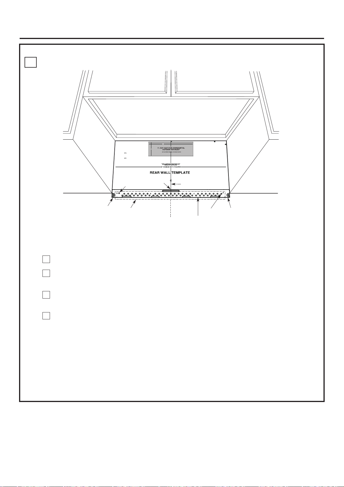
Instrucciones de instalación
D.
ALINEACIÓN DE LA PLACA PARA LA PARED
3/8" TO EDGE
NOTE: IT IS VERY IMPORTANT TO
READ AND FOLLOW THE DI
RECTIONS
IN THE INSTALLATION INSTRUCTIONS
BEFORE PROCEEDI
NG WITH
THIS
REAR WALL TEMPLATE.
This Rear Wall Template serves t
o position the bottom
mounting plate and to locate the horizontal exhaust
outlet.
1. Use a level to check th
at the template is positioned
accurately.
2. Locate and ma
rk at least one stud on the left or
right side of the centerlin
e.
It is important to use at least one wood
screw mounted firmly in a stud to s
upport the weight
itional, evenly spaced
of the microwave. Mark two add
locations for the supp
lied toggle bolts.
3. Drill holes in the marked locatio
ns. Where there is
a stud, drill a 3/16" hole for
wood screws. For hole
that do not line up with a st
ud, drill 5/8" holes for
toggle bolts.
DO NOT INSTALL THE M
OUNTING PLATE
AT THIS TIME.
4. Remove the template from the rear wall.
5. Review the Installation Instru
ction book for your
installation situation.
Darle vuelta a la hoja para consultar la
versión en Español.
Locate and mark
holes to align with h
mounting plat
e.
IMPORTANT:
LOCATE
AT LEAST ONE
STUD ON EITHER SIDE OF
THE CENTERLINE.
MARK THE LOCATION FOR 2
ADDITIONAL, EVENLY
SPACED
TOGGLE BOLTS IN THE MOUNTING PLATE
AREA.
Agujero B
s
oles in the
12"
4"
Muescas de la
línea de centro
Dibula una Inea vertical en la
pared desde el centro del
cumbre del armario.
Trim the rear
Locate and mark
holes to align with hol
mounting plate.
IMPORTANT:
LOCATE
AT LEAST ONE
THE CENTERLINE.
MARK THE LOCATION FOR 2
SPACED
TOGGLE BOLTS IN
AREA.
wall template al
es in the
STUD ON EITHER SIDE OF
ADDITIONAL, EVENLY
THE MOUNTING PLATE
ong the dotted
line.
La línea horizontal
Trace una línea vertical en la pared, en el
1
Área E
centro del espacio cuyo ancho es 30".
Trace una línea horizontal en la pared
2
desde el fondo de "Plantilla de pared
posterior."
Encuentre un travesaño en el área E de la
3
placa de montaje. Consulte la sección 1B:
Encontrar travesa- ños de pared.
Para adherir la placa de montaje al
4
travesaño taladre un agujero de 3/16''.
Taladre un agujero de 5/8'' para tornillo
acodado en otra ubicación (Agujero A o
Agujero B).
NOTA: NO INSTALE LA PLACA EN ESTE
MOMENTO.
Agujero A
C
Trace una línea horizontal en la pared desde el
fondo de "Plantilla de pared posterior".
L
La línea horizontal
NOTA: Los Agujero A y los Agujero B se
encuentran dentro de la regin E. Si tanto el
agujero C como el D no quedan en una viga,
localice una viga en el área E y trace un quinto
círculo que quede alineado con la viga. Es
importante que al menos un tornillo para madera
quede fijado firmemente a una viga, a fin de que
pueda soportar el peso del microondas. Deje a un
lado la placa de instalación.
ES-8
Page 34
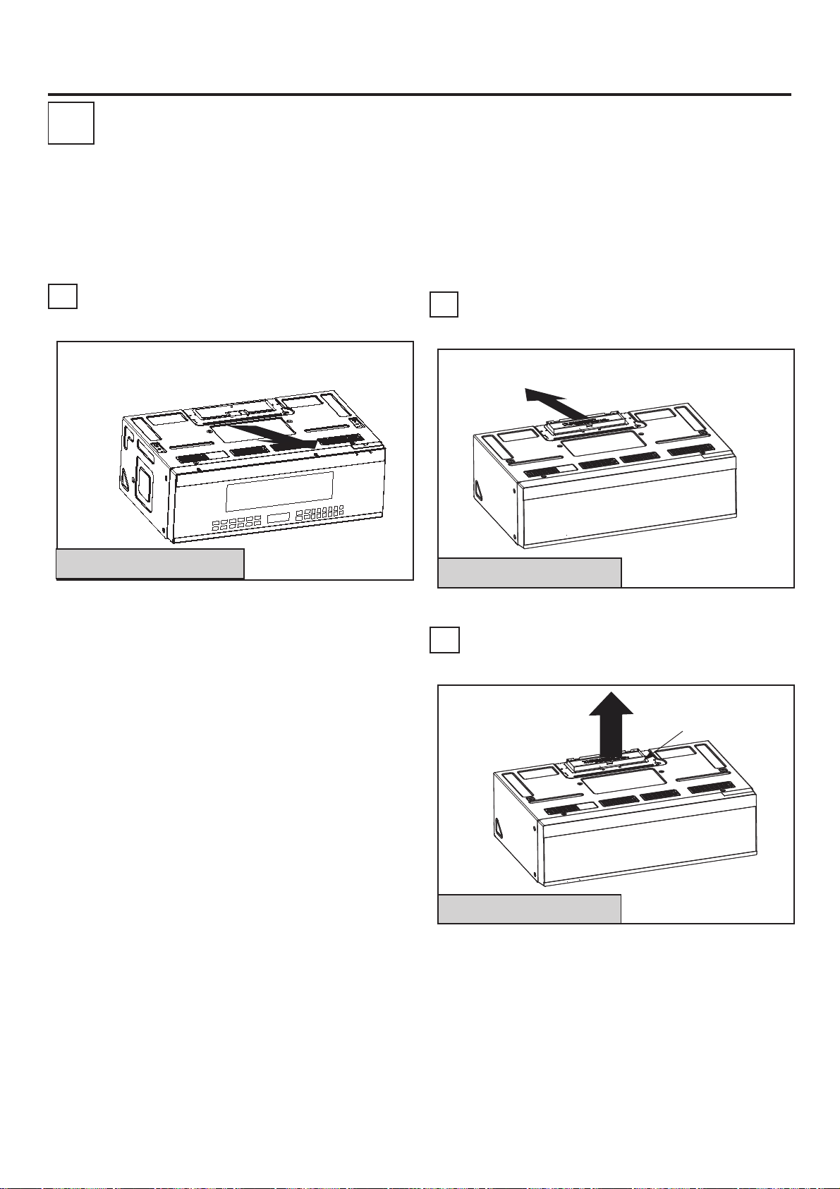
Instrucciones de instalación
2
TIPOS DE INSTALACIÓN
Este horno microondas está diseñado para adaptarse
a los tres tipos siguientes de ventilación:
A.Extracción superior externa (conducto vertical)
B.Extracción trasera externa (conducto horizontal)
C.Recirculación (sin conducto de extracción)
RECIRCULACIÓN (SIN CONDUCTO
A
.
DE EXTRACCIÓN)
(A Elección Entre A, B o C)
NOTA: este horno microondas se ha fábricado para un
sistema de Recirculación. Seleccione el tipo de
ventilación necesario para su instalación y proceda
con las instrucciones de la sección correspondiente.
EXTRACCIÓN TRASERA EXTERNA
B.
(CONDUCTO HORIZONTAL)
El adaptador debe ser
recolocado en la parte trasera,
para permitir la extracción
trasera externa
Consulte la página 10
Los modelos fábricados para un sistema de
extracción basado en la recirculación del aire
vienen con la instalación de fábrica de un filtro
de carbón, el cual ayuda a eliminar el humo/los
vapores y los olores.
Consulte la página 15
C.
EXTRACCIÓN SUPERIOR EXTERNA
(CONDUCTO VERTICAL)
El adaptador está en
posición correcta para la
extracción superior externa
Consulte la página 19
NOTA: lea las páginas 13-14 solamente si va a instalar un sistema de extracción hacia el exterior.
Si tiene planeado realizar una instalación basada en la recirculación del aire dentro de la cocina, continúe con
la páging 10.
ES-9
Page 35
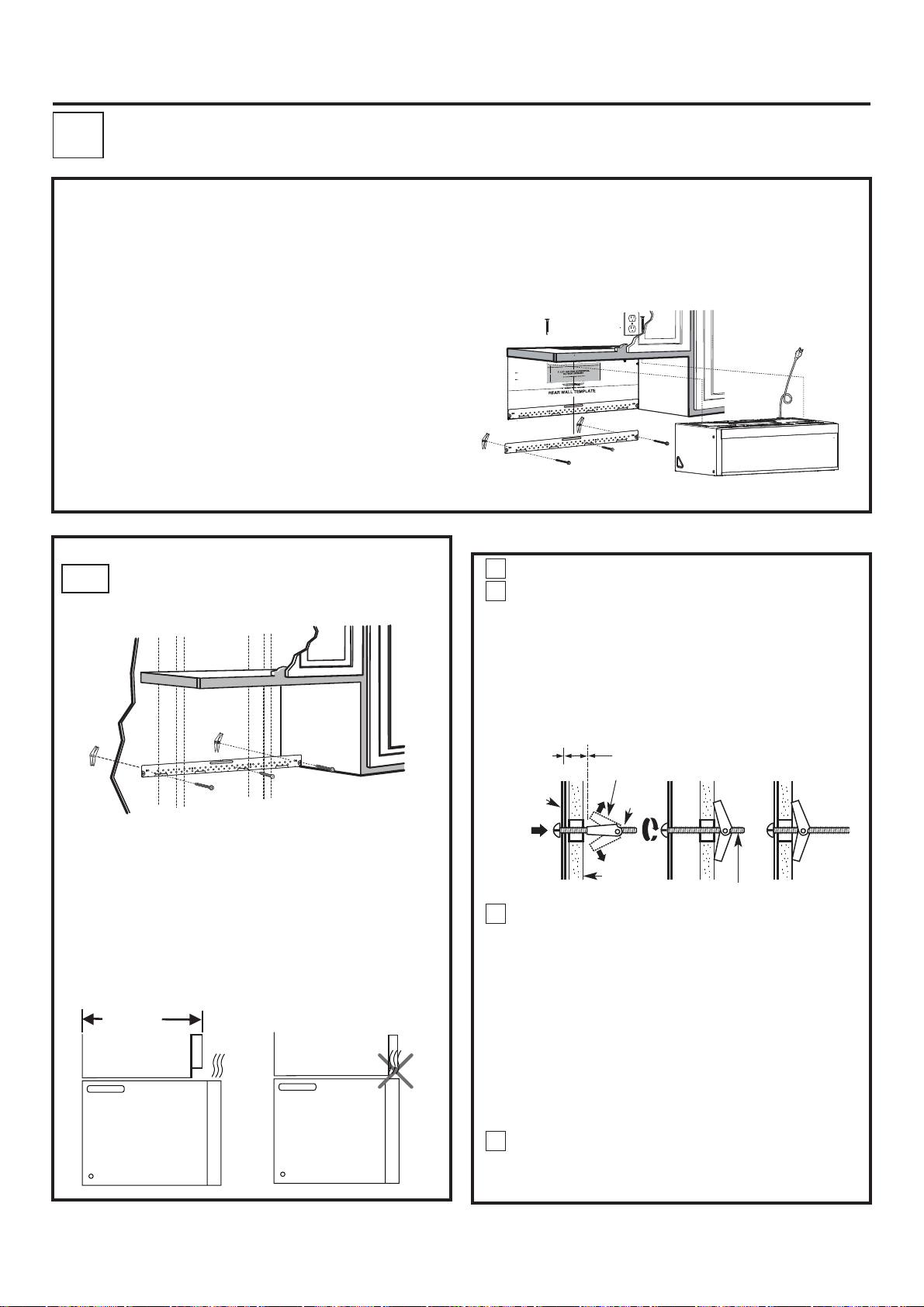
Instrucciones de instalación
RECIRCULACIÓN
A
(Sin Conducto De Extracción)
DESCRIPCIÓN GENERAL DE LA INSTALACIÓN
C1. Montaje de la placa de instalación en la pared
C2. Preparación del gabinete superior
C3. Verificación del conjunto del Placa del Ventilador
C4. Instalación del horno microondas
C5. lnstalación o cambiar del filtro de carbón
NOTAS IMPORTANTES:
• Asegúrese de que los tornillos del motor del
ventilador y la placa del ventilador queden
firmemente apretados al volver a instalarlos. Esto
ayudará a prevenir el exceso de vibraciones.
• Asegúrese de que el cableado del motor quede
debidamente orientado y asegurado, y que los cables
no queden atrapados.
MONTAJE DE LA PLACA DE
A1.
INSTALACIÓN EN LA PARED
TO
T
N
TA
R
PO
M
I
RY
E
V
T IS
I
:
TE
O
N
NS
IO
T
C
E
R
I
D
THE
W
OLLO
F
D
N
A
D
REA
S
ON
CTI
U
TR
NS
ION I
T
ALLA
T
NS
I
THE
N
I
IS
H
T
WITH
G
N
DI
E
CE
O
R
P
E
R
O
F
E
B
ATE.
L
P
TEM
LL
A
AR W
RE
m
tto
o
b
e
th
n
ositio
to p
ves
r
e
s
e
at
l
p
m
Te
12"
ll
Wa
r
a
e
R
s
Thi
t
s
hau
ex
l
a
t
n
o
iz
or
h
e
h
t
e
t
a
c
o
l
to
d
an
ate
g pl
in
nt
u
o
m
.
t
e
utl
o
d
e
ition
s
o
p
is
te
la
mp
e
t
e
h
t
at
h
t
eck
h
c
to
l
ve
e
l
a
se
U
.
1
y.
el
t
accura
r
o
ft
e
l
on the
d
stu
e
n
st o
a
e
l
at
k
r
a
ndm
a
cate
o
L
2.
.
ine
l
r
te
n
e
e c
h
t
of
ide
s
ht
ig
r
d
o
wo
t one
as
e
l
at
use
o
t t
an
rt
po
s im
It i
ht
he weig
t t
or
p
sup
to
d
stu
a
n
i
y
l
m
r
nted fi
mou
w
re
c
s
ed
c
a
p
venlys
e
l,
ona
ti
addi
o
4"
tw
ark
M
.
ve
a
w
icro
m
the
of
s.
lt
o
b
e
l
g
g
to
ed
ppli
u
s
e
h
for t
s
ion
cat
lo
s
i
e
r
he
t
e
r
e
Wh
s.
on
ti
ca
o
l
rked
a
m
the
n
i
s
le
o
h
ll
ri
D
3.
s
ole
h
r
. Fo
ws
e
cr
s
d
woo
or
f
le
o
h
16"
3/
a
l
il
r
d
,
d
a stu
or
f
s
hole
"
/8
l 5
l
i
r
d
tud,
a s
ith
e upw
in
t l
do no
that
ts.
l
bo
le
gg
to
TE
A
L
P
G
IN
T
N
U
MO
E
L TH
AL
T
S
N
I
T
NO
O
D
.
E
IM
T
HIS
T
T
A
.
all
w
e rear
mth
o
fr
te
la
mp
move the te
e
R
4.
r
u
o
y
or
k f
oo
b
n
o
i
t
uc
r
t
ns
I
on
i
t
a
ll
a
t
s
n
I
e
t
w
ieh
v
e
R
.
5
on.
i
t
itua
n s
atio
nstall
i
la
r
a
ult
s
n
o
parac
a
j
o
h
a
l
taa
l
e
u
v
e
arl
D
.
l
o
añ
p
nEs
e
n
ó
i
rs
e
v
e
h
t
in
s
le
ho
th
wi
es to align
ol
h
rk
a
m
nd
a
te
a
Loc
gplate.
tin
un
o
m
:
NT
A
RT
PO
M
I
F
O
E
ID
S
ER
TH
N EI
O
UD
T
S
E
N
T O
S
LEA
T
A
E
T
CA
O
L
.
RLINE
E
NT
E
C
E
H
T
LY
EVEN
L,
IONA
T
I
ADD
2
R
O
F
N
O
CATI
O
L
HE
KT
MAR
E
AT
G PL
IN
NT
U
O
M
N THE
I
S
T
E BOL
GGL
O
T
D
ACE
P
S
.
EA
R
A
.
ne
li
ed
t
t
do
e
h
t
along
ate
pl
all tem
w
r
ea
r
he
t
m
i
Tr
Quite las tuercas de mariposa de los tornillos.
1
Inserte los tornillos en la placa de instalación, a
2
través de los agujeros taladrados en las partes
de la pared que no son viga (los paneles) y
vuelva a insertar las tuercas de mariposa hasta
3/4” (19 mm) de cada tornillo.
E
G
ED
TO
"
8
3/
.
e
lin
d
te
ot
d
he
t
g
lon
a
e
at
pl
m
e
t
l
l
r wa
ea
r
he
t
rim
T
n the
i
es
ol
h
th
gn wi
es to ali
ol
h
k
mar
e and
t
Loca
.
e
ta
l
p
g
n
it
n
u
o
m
:
NT
A
RT
IMPO
F
E O
R SID
HE
N EIT
O
D
U
ST
E
ON
T
EAS
T L
A
E
T
LOCA
E.
IN
L
ER
T
EN
C
THE
LY
EN
V
E
L,
A
N
O
I
T
2 ADDI
R
O
F
ION
T
A
C
LO
HE
T
RK
A
M
LATE
P
UNTING
N THE MO
LTS I
E BO
GL
G
O
T
D
E
AC
P
S
EA.
AR
Fije la placa en la pared con los tornillos de fiador.
Al menos un tornillo para madera debe ser utilizado
para fijar la placa a una viga de la pared.
NOTA: Si la profundidad del gabinete incluyendo
las puertas es mayor de 13” entonces la
unidad debe alejarse de la pared con
materiales adecuados que soporten 150 lbs
para permitir una ventilación
adecuada/toma de aire.
13.8" MAX.
(35 cm)
Gabinete
Gabinete
Para utilizar tornillos de fiador:
El espacio que ocupan los
tornillos fiadores es superior
al grueso de la pared
Placa de
montaje
Coloque la placa de instalación contra la pared
3
e inserte las tuercas de mariposa en los
agujeros de la pared, a fin de instalar la placa.
NOTA: Antes de apretar los tornillos de fiador y el
tornillo para madera, asegúrese de que las
lengüetas de la placa de instalación toquen la parte
inferior del gabinete cuando sean empujadas a ras
contra la pared, y que la placa quede debidamente
centrada bajo el gabinete.
PRECAUCIÓN: Tenga cuidado de evitar que sus
dedos queden atrapados entre la parte trasera de
la placa de instalación y la pared.
Apriete todos los tornillos. Tire de la placa
4
alejándola de la pared, a fin de que resulte más
fácil apretar los tornillos.
Tuercas de mariposa
Tornillo
fiador
Pared
Extremo de tornillo
ES-10
Page 36
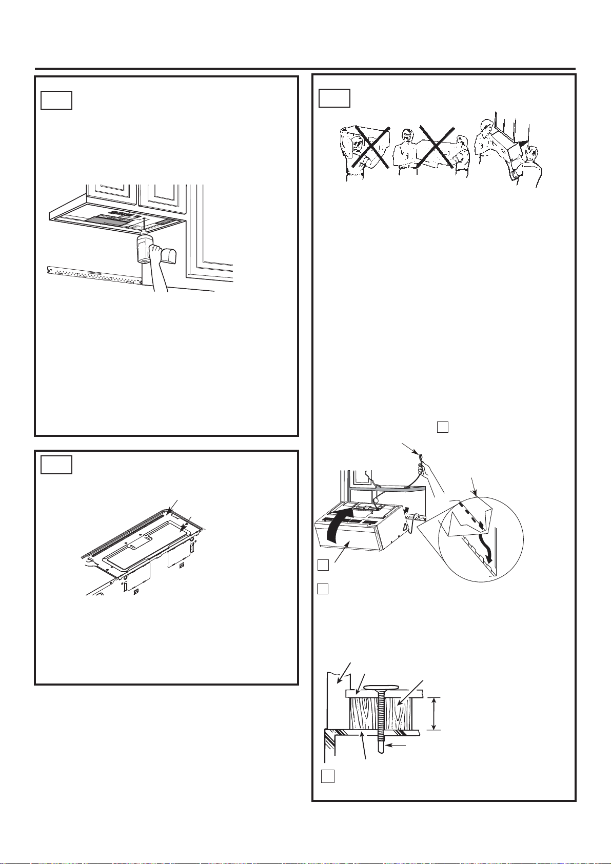
Instrucciones de instalación
USO DE LA PLANTILLA PARA
A2.
EL GABINETE SUPERIOR A FIN
DE PREPARAR EL ÁREA DE
DICHO GABINETE
Es necesario taladrar agujeros para los tornillos de
soporte superior, así como un agujero lo suficientemente
grande para que el cable eléctrico pueda pasar a través.
• Lea las instrucciones de la sección PLANTILLA
PARA EL GABINETE SUPERIOR.
• Adhiera con cinta la plantilla al gabinete superior.
NOTA: Ajuste la placa superior de acuerdo a si el
microondas está siendo separado de la pared
debido a la profundidad del gabinete (más de 13'').
• Taladre los agujeros, siguiendo las instrucciones
de la sección
PLANTILLA PARA EL GABINETE SUPERIOR.
PRECAUCIÓN: cuando taladre los agujeros en la
superficie inferior del gabinete, use gafas
protectoras.
A3.
VERIFICACIÓN DEL CONJUNTO
DEL PLACA DEL VENTILADOR
Placa del ventilador
Placa de cubierta
INSTALACIÓN DEL HORNO
A4.
MICROONDAS
POR RAZONES DE SEGURIDAD PERSONAL Y
PARA FACILITAR LA INSTALACIÓN, SE
RECOMIENDA QUE DOS PERSONAS INSTALEN EL
HORNO MICROONDAS.
IMPORTANTE: No agarre ni use la manija o el
escudo térmico
durante la instalación. No retire los separadores de
cartón entre el escudo térmico y la puerta.
NOTA: Si el gabinete es metálico, use una moldura
aislante de nylon alrededor del agujero para el
cable eléctrico, a fin de evitar cortes en el cable.
NOTA: Se recomienda el uso de bloques de relleno
si la parte delantera del gabinete sobresale debajo
del estante inferior del gabinete.
IMPORTANTE: Si no se usan bloques de relleno,
pueden producirse daños en la carcasa por apretar
demasiado los tornillos.
NOTA: cuando instale el horno
microon- das, pase el cable
eléctrico a través del agujero
correspondiente de la superficie
inferior del gabinete superior:
Mantén-galo tenso/recto durante
los pasos 1 a 3. No permita que el
cable quede atrapado ni levante el
horno tirando del cable.
Levante el microondas,
1
inclínelo hacia adelante y
enganche las ranuras (situadas
en el borde trasero inferior) a
las cuatro lengüetas inferiores
de la placa de instalación.
• Coloque el microondas en posición vertical,
con la parte superior hacia arriba.
• Chequear siel placa del ventilador está
instalado correcta-mente en el horno.
ES-11
Gire la parte delantera del
2
horno hacia arriba, contra la
superficie inferior del gabinete.
Inserte un tornillo autoalineante a través del agujero del centro
3
del gabinete superior: Fije temporalmente el horno apretando el
tornillo al menos dos vueltas completas despisés de que el
tornillo quede enroscado. (Más adelante se procederá a apretar
completamente el tornillo.) Asegúrese de mantener tenso/recto
el cable eléctrico. Tenga cuidado de evitar que el cable quede
atrapado, especial- mente al realizar la instalación del horno a
ras contra la superficie inferior del gabinete.
Parte delantera del gabinete
Estante inferior del gabinete
Bloque de relleno
Equivalente a la
profundidad de la
superficie hueca del
gabinete
Tornillo autoalineante
Parte superior del horno microondas
Fije el horno microondas al gabinete
4
superior.
Page 37
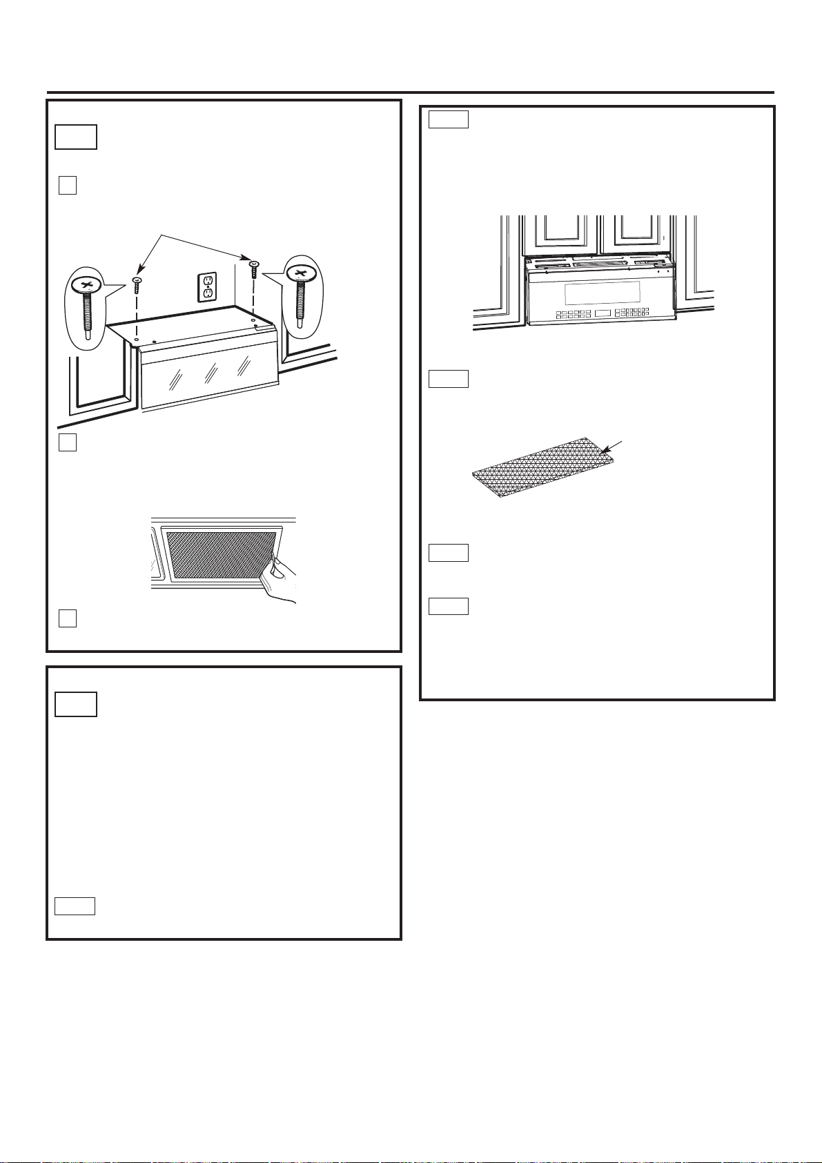
Instrucciones de instalación
A4.
INSTALACIÓN DEL HORNO
MICROONDAS
5
Inserte 2 tornillos autoalineantes a través de los
agujeros exteriores del gabinete superior.
Apriete cada uno de, los tornillos dos vueltas
completas.
6
Apriete los dos tornillos externos a la parte
superior del horno. (Mientras aprieta los
tornillos, mantenga sujeto el horno contra la
pared y el gabinete superior:)
(cont.)
A 5.2
A 5.3
Retire la guía de aire de plástico ubicada
en la parte superior del microondas.
Cambie el filtro de carbón.
Filtro de
carbón
7
Instale los filtros de grasa. Consulte el Manual
del usuario provisto con el microondas.
Instalación o cambiar del filtro
A5.
de carbón (Algunos Modelos)
NOTA: El filtro de carbón está instalado de
fábrica en algunos modelos. Consulte la sección
Uso y cuidado para ver si su dispositivo lo tiene
y para leer información sobre su remplazo.
Para el modelo sin la puerta de acceso al filtro
de recirculación, siga las instrucciones para
remplazar o instalar un filtro de carbon.
Desconecte el microondas del suministro
A 5.1
eléctrico.
A 5.4
A 5.5
Instale la guía de aire de plástico ubicada
en la parte superior del microondas.
Cierre la puerta del microondas. Enchufe el
horno microondas o vuelva a conectar la
alimentación.
ES-12
Page 38
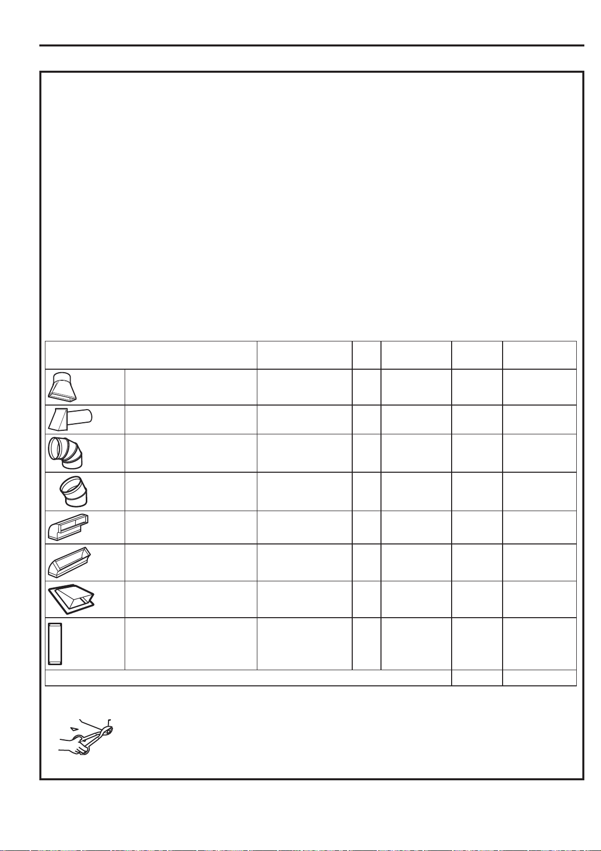
Instrucciones de instalación
INSTRUCCIONES DE INSTALACIÓN DE CONDUCTOS DE ESCAPE EXTERNAS
NOTA: en caso de que sea necesario instalar conductos,
tenga en cuenta que el largo total de los conductos.
rectangulares (ancho de 3
o redondos (diámetro de 5" ó 12,7 cm) /(diámetro de 6" ó
15,2 cm) NO debe ser superior a 140 pies ( 42,7 m).
La ventilación exterior requiere el uso de un
CONDUCTO PARA CAMPANA EXTRACTORA. Lea con
atención las siguientes recomendacio- nes.
NOTA: es importante que se instale el sistema de
ventilación siguiendo la ruta más directa y con el menor
número posible de codos. Esto garan- tizará la salida
fluida del aire por los conductos de extracción y evitará
cualquier bloqueo. Asimismo, asegúrese de que los
reguladores de extracción se muevan libremente y nada
bloquee los conductos.
1/4" × 10" u 8,2 cm × 25,4 cm)
Conexión de escape:
El adaptador fue diseñado para concordar con un ducto
rectancular estpandar 3
requiere de un ducto redondo, se debe utilizar un
adaptador de transición.
Un ducto con un diámetro de 5" (12.7cm) / 6" (15.2cm) es
aceptable.
PIEZAS DEL CONDUCTO x =
1/4" x 10" (8.2 x 25.4 cm). Si se
Adaptador de unión entre
el conducto rectangular y
el redondo*
Tapa de salida a la pared
LARGO (MEDIDAS
EQUIVALENTES)
5 pies (1,5 m) ( )
40 pies (12,2 m)
Largo máximo del conducto:
Para lograr una salida satisfactoria del aire, el largo total
del conducto rectangular con un ancho de 3
(8,2 × 25,4 cm) o redondo con un diámetro de 5" (12,7
cm) /6" (15,2 cm) no debe ser mayor que 140 pies (42,7
m).
Los codos, los adaptadores, las tapas de salida
al techo o a la pared, etc.,
resistencia adicional al flujo del aire y son equivalentes a
una sección de conducto recto cuyo largo es mayor que
su tamaño físico real. Cuando calcule el largo total del
conducto, añada el largo equivalente de cada uno de los
adaptadores, codos, etc., más el largo de todas las
secciones rectas del conducto. La tabla siguiente contiene
infonnación para saber cómo calcular el largo total (en
medidas equivalentes) del sistema de conductos, a partir
del largo aproximado en pies de algunos
conductos/adaptadores/codos, etc. estándar.
No DE UNIDADESUTILIZADAS
x
x
( )
1/4" × 10"
representan áreas de
LARGO (MEDIDAS
EQUIVALENTES)
=
=
Pies o m
(metros)
Pies o m
(metros)
Codo de 90°
Codo de 45°
Codo de 90°
Codo de 45°
Tapa d salida al techo
Conducto recto redondo de
6" (15,2 cm) de diámetro o
rectangular de 3
(8,2 × 25,4 cm) de ancho
Largo total del sistema de conductos
*IMPORTANTE: si se utiliza un
adaptador de unión entre el conducto
rectangular y el redondo, los bordes
inferiores del regulador de extractión
tendrán que ser recortados (con una
tijera para hojalata), a fin de que se
ajusten y permitan el libre
mocvimiento del regulador.
1/4" × 10"
10 pies (3 m)
5 pies (1,5 m)
25 pies (7,6 m)
5 pies (1,5 m)
24 pies (7,3 m)
1pies (0,3m)
x
( )
x
( )
x
( )
x
( )
x
( )
x
( )
Los largos (en medidas equivalentes) de las
piezas del conducto están basados en pruebas
reales y se ajustan a los requisitos para un buen
rendimiento de ventilación con cualquier
campana eatractora.
=
=
=
=
=
=
Pies o m
(metros)
Pies o m
(metros)
Pies o m
(metros)
Pies o m
(metros)
Pies o m
(metros)
Pies o m
(metros)
Pies o m (metros)
ES-13
Page 39
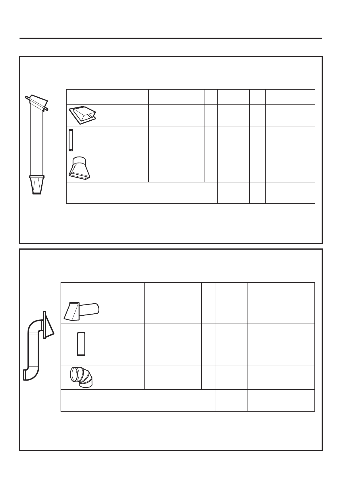
Instrucciones de instalación
CONDUCTOS DE ESCAPE EXTERNAS
EXTRACCIÓN SUPERIOR EXTERNA (SÓLO EJEMPLO)
La siguiente tabla contiene un ejemplo de uno posible instalación de un sistema de conducto de
extracción.
PIEZAS DEL
CONDUCTO
Tapa de
salida a la
pared
Conducto recto
de 12 pies (3,6 m)
y diámetro de 6"
(15,2 cm)
Adaptador de unión
entre el conducto
rectangular y el
redondo*
Los largos (en medidas equivalentes) de las piezas del
conducto están basados en pruebas reales y se ajustan
a los requisitos para un buen rendimiento de ventilación
con cualquier campana extractora.
LARGO (MEDIDAS
EQUIVALENTES)
24 pies (7,3 m)
12 pies (3,6 m)
5 pies (1,5 m)
No DE UNIDADES-
x =
UTILIZADAS
x
( 1 )
x
( 1 )
x
( 1 )
Largo total
del sistema
de conductos
=
=
=
* IMPORTANTE: si se utiliza un adaptador le unión entre el conducto rectangular y el
redondo, los bordes inferiores del regulador
de extracción tendrán que ser recortados (con una tijera para hojalata), a fin de que se
ajusten y permitan el libre
movimiento del regulador.
EXTRACCIÓN TRASERA EXTERNA (SÓLO EJEMPLO)
La siguiente tabla contiene un ejemplo de una posible instalación de un sistema de conducto de
extracción.
LARGO (MEDIDAS
EQUIVALENTES)
24 pies (7,3 m)
12 pies (3,6 m)
5 pies (1,5 m)
41 pies (12,5 m)
PIEZAS DEL
CONDUCTO
Tapa de
salida a la
pared
Conducto recto
rectangular de 3
pies (0,9 m) de
largo (3
10" (8,2 cm ×
25,4 cm) de
ancho
Codo de 90°
Los largos (en medidas equivalentes) de las piezas del
conducto están basados en pruebas reales y se ajustan
a los requisitos para un buen rendimiento de ventilación
con cualquier campana extractora.
1/4" ×
LARGO (MEDIDAS
EQUIVALENTES)
40 pies (12,2 m)
3 pies (0.9 m)
10 pies (3 m)
No DE UNIDADES-
x =
UTILIZADAS
x
( 1 )
x
( 1 )
x
( 1 )
Largo total
del sistema
de conductos
LARGO (MEDIDAS
EQUIVALENTES)
=
40 pies (12,2 m)
=
3 pies (0.9 m)
=
20 pies (3 m)
63 pies (19,2 m)
NOTA: en el caso de extracción por la parte trasera, hay que tener cuidado de alinear los
conductos de extracción con el espacio entre las vigas
(el entramado), o bien que la pared haya sido preparada durante su construcción para dejar
suficiente espacio entre las vigas para el sistema
de extracción.
ES-14
Page 40
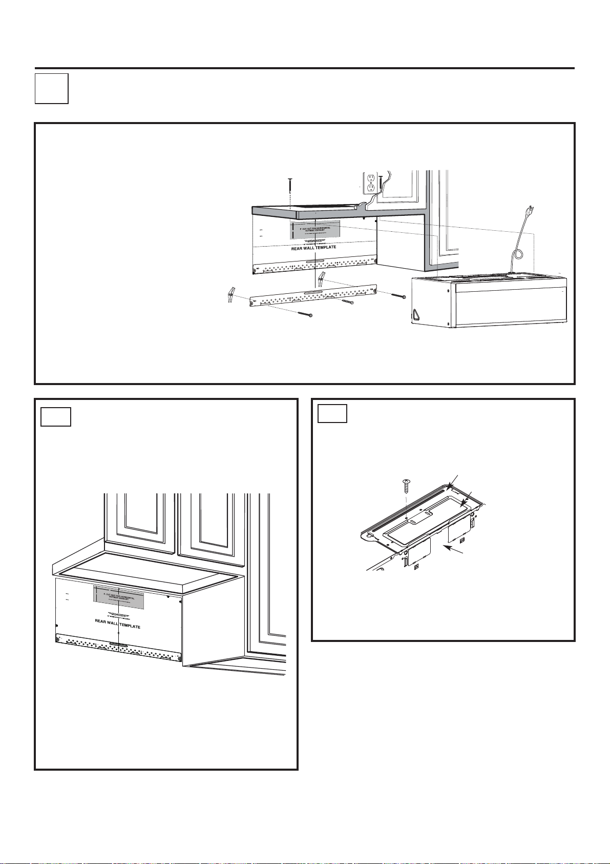
Instrucciones de instalación
EXTRACCIÓN TRASERA EXTERNA (Conducto
B
Horizontal)
INSTALLATION OVERVIEW
B1. Preparación de la pared trasera
B2. Desinstalación del placa del ventilador
B3. Montaje de la placa de instalación en
la pared
B4. Preparación del gabinete superior
B5. Ajuste del ventilador
B6. Instalación del horno microondas
NOTAS IMPORTANTES:
• Asegúrese de que los tornillos del
motor del ventilador y la placa del
ventilador queden firmemente
apretados al volver a instalarlos.
Esto ayudará a prevenir el exceso de
vibraciones.
• Asegúrese de que el cableado del
motor quede debidamente orientado y
asegurado, y que los cables no queden
atrapados.
O
T
NT
TA
OR
P
M
RY I
E
V
IT IS
:
TE
O
N
NS
IO
CT
RE
I
D
HE
T
W
O
LL
ND FO
A
D
REA
S
ION
CT
U
R
T
NS
I
N
O
I
T
LLA
A
NST
I
THE
N
I
IS
H
WITH T
DING
CEE
O
R
P
RE
O
F
E
B
.
TE
A
MPL
TE
L
L
A
R W
A
RE
m
otto
b
e
th
n
o
ti
i
s
o
p
o
t
s
e
serv
e
t
a
l
mp
e
T
ll
Wa
r
a
e
R
s
hi
T
t
s
hau
tal ex
n
o
horiz
e
h
t
te
ca
o
eand to l
t
a
l
p
g
n
ti
n
ou
m
t.
e
outl
ed
on
iti
os
is p
ate
l
p
em
t
e
at th
h
k t
ec
ch
to
l
ve
le
a
e
Us
.
1
y.
el
at
r
accu
t or
ef
l
n the
o
d
estu
on
t
t leas
k a
ar
m
nd
e a
t
oca
2. L
.
e
in
rl
e
nt
e
the c
f
o
de
ight si
r
wood
ne
t o
as
le
t
a
use
o
t t
an
ort
p
im
is
It
t
h
g
e wei
h
t t
or
tud to supp
s
n a
y i
l
rm
fi
d
nte
u
o
w m
e
cr
s
aced
ysp
al, evenl
ion
addit
wo
k t
ar
M
.
ave
w
o
micr
e
ofth
ts.
l
bo
gle
g
o
t
ed
i
l
upp
s
e
th
or
f
s
ation
c
o
l
s
i
there
e
r
he
s.W
n
o
i
t
loca
d
e
ark
m
e
th
n
i
s
ole
h
ll
i
r
D
3.
s
le
o
h
For
.
ws
e
r
d sc
woo
or
f
le
o
h
"
6
1
/
3
a
ill
dr
d,
u
a st
r
s fo
le
ho
"
8
/
5
l
il
r
d, d
tu
s
a
ith
w
p
u
ine
l
not
o
td
ha
t
.
ts
l
bo
le
gg
o
t
E
LAT
G P
IN
T
UN
HE MO
L T
NSTAL
T I
DO NO
.
E
IM
T
S
HI
T
AT
wall.
r
a
e
r
e
h
tm
o
te fr
la
p
tem
the
ove
m
e
R
.
4
r
ou
y
or
k f
o
tion bo
c
u
r
nst
I
tion
a
ll
a
st
n
I
e
h
t
w
e
i
v
e
R
5.
.
on
i
t
ua
t
i
n s
o
i
at
ll
sta
in
a
l
ar
t
l
u
s
con
ra
ap
a
jo
ha
l
a
a
t
l
vue
e
l
Dar
ol.
ñ
a
Esp
n
e
n
ó
si
r
e
v
e
n th
i
s
le
o
h
ith
w
align
rk holes to
a
d m
n
cate a
Lo
te.
a
pl
g
tin
n
u
o
m
:
ANT
RT
O
P
IM
F
O
E
ID
S
ER
N EITH
O
STUD
E
ON
ST
EA
L
T
E A
T
A
LOC
.
E
LIN
R
E
ENT
C
E
TH
Y
AL, EVENL
N
2 ADDITIO
R
FO
TION
A
C
HE LO
T
K
AR
M
E
T
PLA
MOUNTING
N THE
I
TS
L
BO
LE
OGG
T
D
PACE
S
.
EA
R
A
.
e
n
d li
e
tt
o
d
e
th
g
on
l
a
te
a
pl
m
e
ll t
a
w
r
a
e
r
he
t
Trim
E
EDG
TO
"
8
3/
12"
4"
L
IM
L
T
M
SP
AR
.
e
n
li
d
e
t
ot
d
he
t
long
a
e
mplat
e
l t
wal
ar
e
he r
t
Trim
the
n
es i
l
ho
h
it
w
gn
li
a
to
les
o
h
k
r
a
m
nd
a
ate
c
o
.
e
t
a
l
i
p
nu
g
n
t
om
:
T
N
A
T
OR
P
OF
E
D
I
S
R
N EITHE
O
D
U
EST
ON
T
S
A
E
L
AT
E
T
OCA
E.
N
I
L
R
E
NT
E
C
HE
Y
NL
E
, EV
L
A
N
O
ITI
DD
A
2
FOR
N
IO
CAT
O
L
HE
T
RK
A
E
T
LA
P
G
OUNTIN
M
E
H
T
IN
S
OLT
B
GGLE
TO
D
CE
A
EA.
PREPARACIÓN DE LA PARED
B1.
TRASERA PARA LA SALIDA
DE EXTRACCIÓN TRASERA
Es necesario realizar un corte en la pared trasera
para crear una
abertura para la salida de extracción externa.
NO
TE
: IT IS VE
R
E
RY IM
AD
A
POR
ND
FOLL
T
IN T
ANT
OW
HE INSTA
TO
TH
E
DIR
BEFO
L
LATIO
ECTIONS
RE
N
PROCEEDING
INSTR
RE
AR
U
CTIO
WALL
NS
WITH
TEMPLATE
Th
THI
is
Rear
S
W
.
all
m
Te
ount
m
pl
in
at
g
e s
pl
er
a
te
v
es
ou
a
nd
t
t
let
o
t
p
o
.
osit
lo
c
i
a
on
t
e
t
t
h
he
1.
e bot
Us
hori
e
t
om
z
a
o
ntal
le
vel
exhaust
t
o check
accurat
that
ely.
t
h
e
2.
t
e
Locat
m
pla
t
e
e
and
is
positione
mark
right
a
t
d
side
lea
s
t
on
o
f
t
e
h
e
st
ce
ud
nt
on the
erl
ine.
It
is
l
ef
im
t
or
portant t
scr
ew
mou
o
u
se at
n
t
e
d
of
leas
f
irmly
th
e
t
in
microw
on
a
e wood
st
ud
ave.
loca
t
o
Mar
s
ti
up
on
port
k
s
t
wo a
f
or
t
he
t
h
ddition
e
wei
3.
s
Dr
uppl
ght
ill
al,
ied
h
oles
ev
t
ogg
enly
in
le
t
spa
h
bolt
e
a st
m
ced
s.
arked loca
ud,
dri
ll
a
3
t
io
/
t
1
hat
ns.
6"
ho
Wh
do
le
n
ere
f
ot li
or wood
t
ne
h
er
t
up
oggle
e
i
s
screws. F
with
b
olts
a stud,
.
o
r
drill
holes
5
/
8
"
D
hole
O
NOT
s
f
or
AT
IN
T
S
HI
T
S
ALL
T
I
M
T
E.
HE
4.
Rem
MO
UN
o
ve
T
I
NG
the
P
5.
t
emplat
LAT
R
eview
E
e
from
th
e I
the
nstal
in
rear
stallat
la
t
io
wall.
n
io
In
n
s
tr
situat
uc
t
ion
io
n.
bo
o
k
f
or
y
our
Darle
vu
elta
a
ver
la
ho
sión
ja
pa
en
r
a
Espa
co
n
ñ
sul
ol.
tar
la
Lo
cate
and
mark hol
mou
es to
nti
ng p
alig
late
n with holes
.
IMP
O
RTA
in the
NT:
LOCATE
AT LE
AST ON
TH
E
C
ENTER
E
STU
D
LIN
O
M
E
N
A
.
EITH
R
K TH
ER
E L
S
OC
ID
E
SP
AT
O
ACE
ION FOR
F
D TOGG
2 AD
AREA.
LE BO
D
IT
I
O
LTS IN
NAL,
EVENLY
TH
E
MOUNTIN
G
PLA
TE
Trim the
r
ea
r wa
ll templa
te a
l
o
n
g the d
otted
line.
• Lea las instrucciones de la sección PLANTILLA
PARA LA PARED TRASERA.
• Adhiera con cinta la plantilla a la pared trasera.
• Realice el corte de la abertura, siguiendo las
instrucciones de
la sección PLANTILLA PARA LA PARED TRASERA.
3
/8" TO E
D
GE
12"
4"
Tri
m
the
rea
r
wal
l
te
mpla
te
a
l
o
ng
the
d
otted
lin
e
.
Lo
cate
and
mar
k holes to
mo
unti
ng
a
p
lign w
late
.
ith h
IMPORTA
o
les in the
NT:
LO
CAT
E
AT LE
AST ON
TH
E CE
E
N
STU
TER
D O
LIN
MA
E.
N EIT
RK TH
H
ER SIDE
E
L
OCAT
SP
O
ACE
IO
F
N FOR
D TOGG
2 AD
LE
AR
DIT
BOLTS
EA.
IO
NAL
IN
, EVEN
THE
M
LY
OU
NTIN
G PLATE
B2.
QUITAR LA PLACA DEL
SOPLADOR
Retire y guarde el tornillo que sujeta la placa
del soplador al microondas. Levante la placa
del soplador.
• La placa de cubierta se instala con la placa
del soplador, no es necesario separarla.
Placa del soplador
Placa de cubierta
Parte trasera del
microondas
ES-15
Page 41
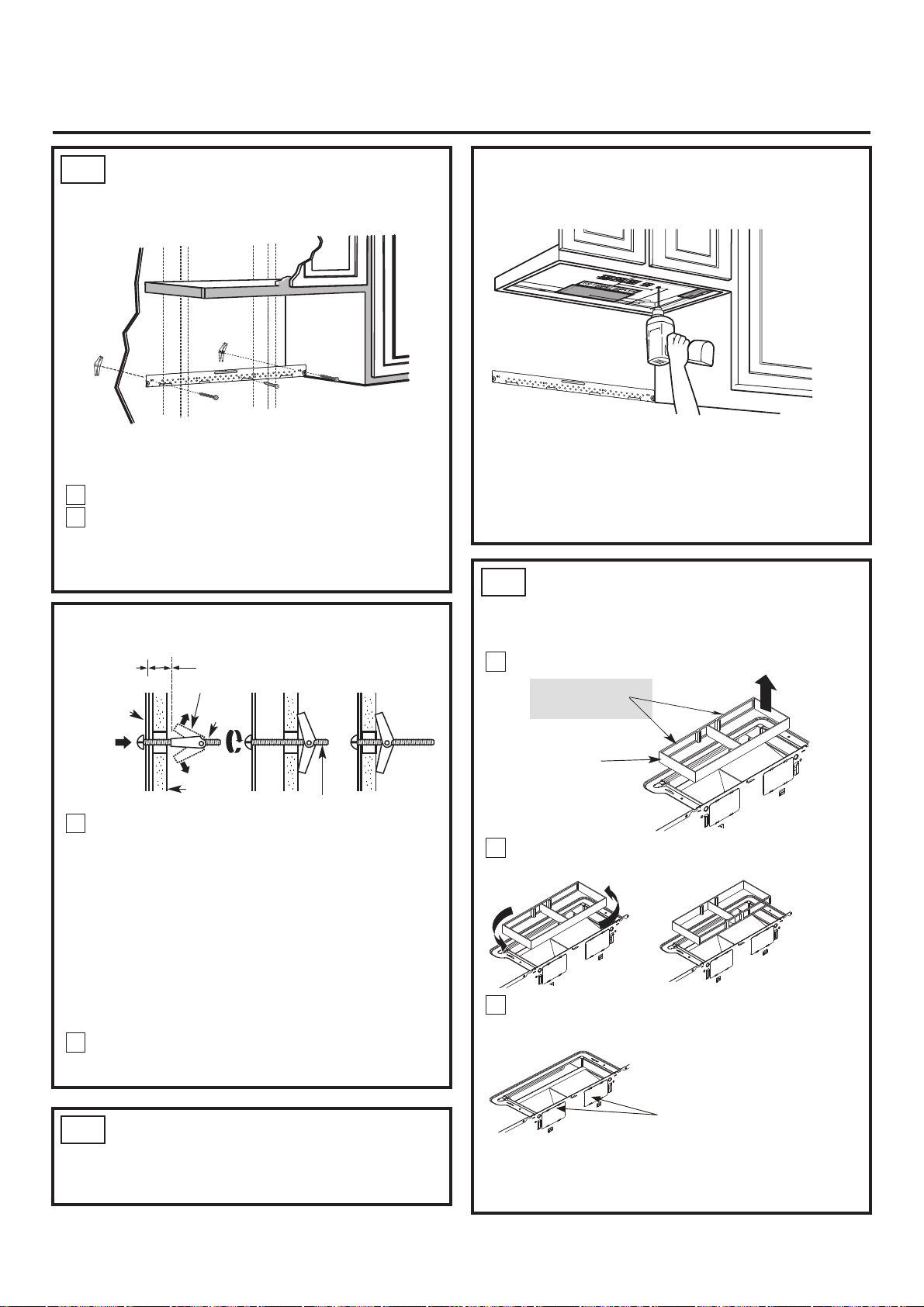
Instrucciones de instalación
B3.
MONTAJE DE INSTALACIÓN
LA PLACA DE EN LA PARED
Fije la placa en la pared con los tornillos de fiador.
Al menos un tornillo para madera debe ser
utilizado para fijar la placa a una viga de la pared.
Quite las tuercas de mariposa de los tornillos.
1
Inserte los tornillos en la placa de instalación, a
2
través de los agujeros taladrados en las partes
de la pared que no son viga (los paneles) y
vuelva a insertar las tuercas de mariposa hasta
3/4" (19 mm) de cada tornillo.
Para utilizar tornillos de fiador:
El espacio que ocupan los tornillos
fiadores es superior al grueso de la pared
Placa de
instalación
Tuercas de mariposa
Tornillo
fiador
Es necesario taladrar agujeros para los tornillos de
soporte superior, realizar un agujero lo suficientemente
grande para que el cable eléctuco pueda pasar a través
y recortar también un hueco to suficientemente amplio
para el adaptador de extracción.
• Lea las instrucciones de la sección PLANTILLA
PARA EL GABINETE SUPERIOR.
• Adhiera con cinta la plantilla al gabinete superior.
• Taladre los agujeros, siguiendo las instrucciones de la
sección PLANTILLA PARA EL GABINETE SUPERIOR.
PRECAUCIÓN: cuando taladre los agujeros en la
superficie inferior del gabinete, use gafas protectoras.
B5.
ADAPTACIÓN DEL
DIRECCIONADOR DE AIRE DE
MICROONDAS PARA LA
SALIDA DE AIRE EXTERIOR
Extraiga con cuidado el direccionador de aire.
1
Antes: Aberturas
hacia delante
Pared
Coloque la placa de instalación contra la pared
3
e inserte las tuercas de mariposa en los
agujeros de la pared, a fin de instalar la placa.
NOTA: antes de apretar los tornillos de fiador y el
tornillo para madera, asegúrese de que las lengüetas
de la placa de instalación toquen la parte inferior del
gabinete cuando sean empujadas a ras contra la
pared, y que la placa quede debidamente centrada
bajo el gabinete.
PRECAUCIÓN: tenga cuidado de evitar que sus
dedos queden atrapados entre la parte trasera de la
placa de instalación y la pared.
Apriete todos los tornillos. Tire de la placa
4
alejándola de la pared, a fin de que resulte más
fácil apretar los tornillos.
B4.
USO DE LA PLANTILLA PARA
Extremo de tornillo
EL GABINETE SUPERIOR A FIN
DE PREPARAR EL AREA DE
DICHO GABINETE
Director de Aire
Rotate the air director counterclockwise 180°
2
Antes de la rotación Después de la rotación
Retire las placas desmontables de la parte
3
trasera del aparato con unas pinzas. (Para
algunos modelos)
Placas desmontables:
Corte las 4 bandas de
cada panel desmontable
y retire las placas de
metal para el flujo de aire
Parte trasera del
microondas
trasero. Tenga cuidado
de eliminar los bordes
afilados creados al retirar
las placas desmontables.
ES-16
Page 42
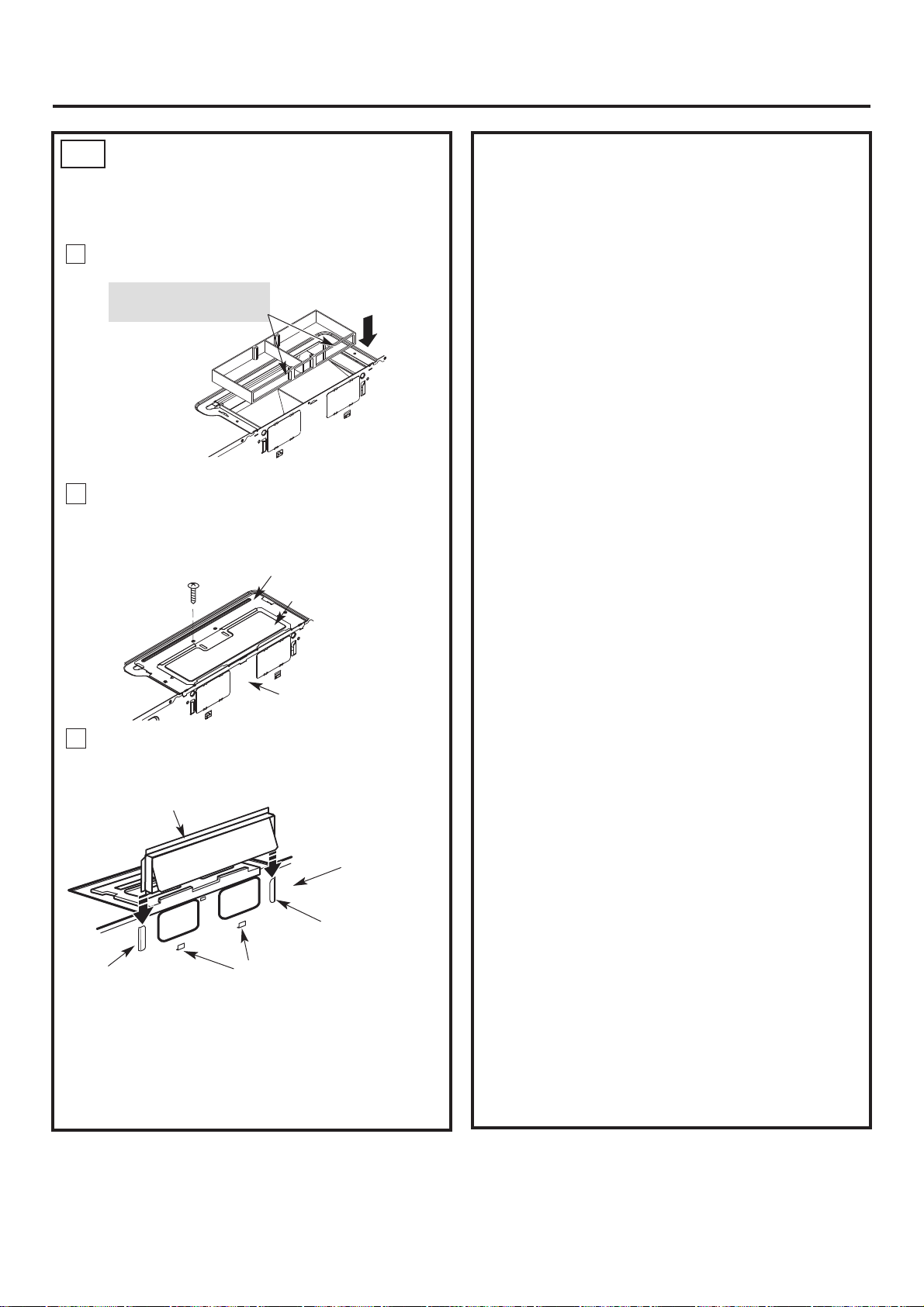
Instrucciones de instalación
B5.
ADAPTACIÓN DEL SOPLADOR
DE MICROONDAS PARA EL
ESCAPE TRASERO EXTERIOR
(cont.)
Vuelva a colocar el direccionador de aire en la
4
abertura.
DESPUÉS: Aberturas del
direccionador de aire
mirando hacia atrás
5
Fije la placa del soplador al microondas con el
tornillo original.
Placa del soplador
Placa de cubierta
Se ha dejado en blanco
Parte trasera del
microondas
Fije el adaptador de escape a la parte trasera
6
del horno deslizándolo en las guías de la parte
superior central de la parte trasera del horno.
Adaptador
Parte trasera del
microondas
Guía
Guía
Presione firmemente hasta que quede en las
lengüetas de bloqueo inferiores. Asegúrese de que
la bisagra de la compuerta esté instalada de forma
que quede en la parte superior y que la compuerta
gire libremente.
Lengüetas de
bloqueo
intencionadamente.
ES-17
Page 43
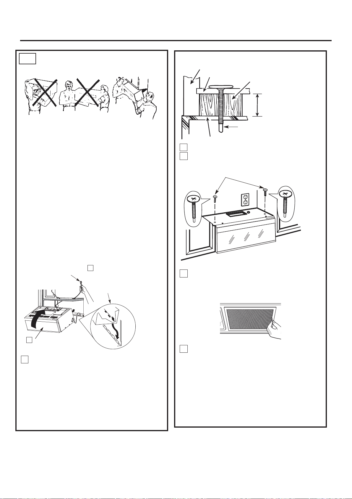
Instrucciones de instalación
B6.
INSTALACIÓN DEL HORNO
MICROONDAS
POR RAZONES DE SEGURIDAD PERSONAL Y PARA
FACILITAR LA INSTALACIÓN, SE RECOMIENDA
QUEDOS PERSONAS INSTALEN EL HORNO
MICROONDAS.
IMPORTANTE:No agarre ni use la manija o el escudo
térmico durante la instalación. No retire los
separadores de cartón entre el escudo térmico y la
puerta.
NOTA: Si el gabinete es metálico, use una moldura
aislante de nylon alrededor del agujero para el cable
eléctrico, a fin de evitar cortes en el cable.
NOTA: Se recomienda el uso de bloques de relleno si
la parte delantera del gabinete sobresale debajo del
estante inferior del gabinete.
IMPORTANTE: Si no se usan bloques de relleno,
pueden producirse daños en la carcasa por apretar
demasiado los tornillos.
NOTA: cuando instale el horno
microondas, ease el cable eléctrico a
través del agujero correspondiente
de la superficie inferior del gabinete
superior Mantengalo tenso recto
durante los pasos 1 a 3. No permita
que el cable quede atrapado ni
levante el horno tirando del cable.
1
Levante el microondas, inclínelo
hacia adelante y enganche las
ranuras (situadas en el borde trasero
inferior) a las cuatro lengüetas
inferiores de la placa de instalación.
Parte delantera del gabinete
Estante inferior del gabinete
Bloque de relleno
Tornillo autoalineante
Parte superior del horno microondas
Fije el horno microondas al gabinete superior.
4
Inserte 2 tornillos autoalineantes a través de
5
Equivalente a la
profundidad de la
superficie hueca del
gabinete
los agujeros exteriores del gabinete superior.
Apriete cede uno de los tornillos dos vueltas
completas.
Apriete los dos tornillos externos a la parte
6
superior del horno. (Mientras aprieta los tornillos,
mantenga sujeto el horno contra la pared y el
gabinete superior)
2
Gire la parte delantera del
horno hacia arriba, contra la
superficie inferior del gabinete.
Inserte un tornillo autoalineante a través del
3
agujero del centro del gabinete superior: Fije
temporalmente el horno apretando el tornillo
al menos dos vueltas completas despisés de
que el tornillo quede enroscado. (Más adelante
se procederá a apretar completamente el
tornillo.) Asegúrese de mantener tenso/recto
el cable eléctrico. Tenga cuidado de evitar que
el cable quede atrapado, especialmente al
realizar la instalación del horno a ras contra la
superficie inferior del gabinete.
Instale los filtros de grasa. Consulte el Manual del
7
usuario provisto con el microondas.
IMPORTANTE: retire los separadores de cartón
entre el escudo térmico y la puerta
ES-18
Page 44
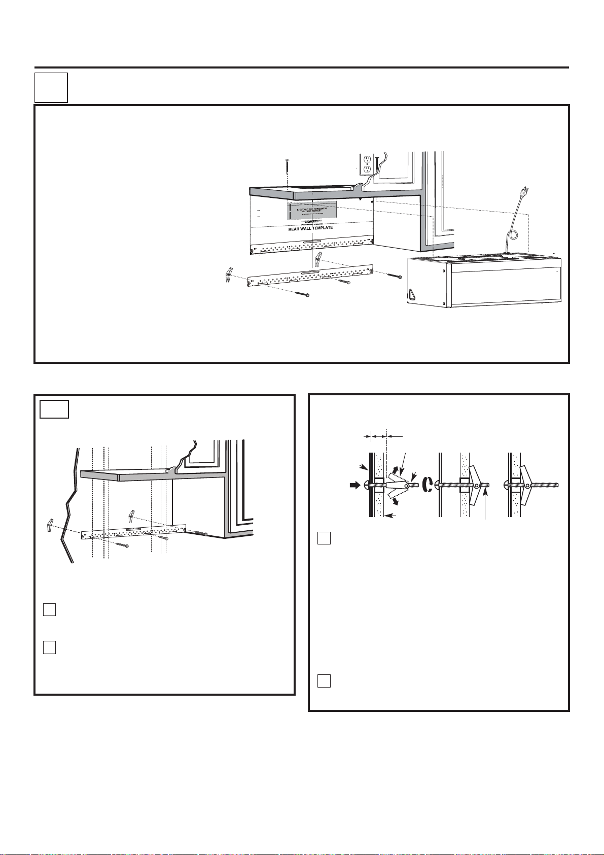
Instrucciones de instalación
EXTRACCIÓN SUPERIOR EXTERNA (conducto vertica)
C
DESCRIPCIÓN GENERAL DE LA INSTALACIÓN
A1. Montaje de la placa de instalación en la pared.
A2. Preparación del gabinete superior.
A3. Ajuste del ventilador del microondas para
la extracción superior externa.
A4. Verificación del funcionamiento del
regulador de extracción.
A5. Instalación del horno microondas. A6.
Ajuste del adaptador de extracción.
A7. Acoplamiento del sistema de conducto
NOTAS IMPORTANTES:
• Asegúrese de que los tornillos
del-motor del ventilador y la placa del
ventilador queden firmemente
apretados al volver a instalarlos. Esto
ayudará a prevenir el exceso de
vibraciones.
• Asegúrese de que el cableado del
motor quede debidamente orientado y
asegurado, y que los cables no queden
atrapados.
O
NT T
TA
OR
P
M
RY I
E
V
IT IS
:
TE
O
N
NS
IO
RECT
I
D
THE
W
O
LL
ND FO
A
D
REA
S
ION
CT
TRU
NS
I
N
O
I
T
LLA
A
NST
I
IN THE
IS
H
T
ITH
W
DING
CEE
O
R
P
RE
O
F
E
B
.
TE
A
EMPL
T
L
L
A
REAR W
ottom
b
e
th
n
o
ti
i
s
o
p
o
t
s
ve
r
e
s
e
t
a
l
p
m
Te
ll
Wa
r
a
e
R
s
hi
T
t
s
hau
tal ex
n
o
z
i
or
h
e
h
t
te
ca
o
d to l
an
e
t
a
l
p
g
n
ti
n
u
mo
t.
e
utl
o
itioned
os
is p
late
p
em
t
e
at th
h
k t
ec
ch
to
l
ve
e
l
a
e
Us
.
1
y.
l
e
at
r
cu
ac
or
eft
l
e
n th
o
d
estu
n
t o
as
e
t l
rk a
a
m
nd
e a
t
oca
2. L
.
e
in
rl
e
nt
e
the c
f
o
de
right si
wood
ne
o
t
as
e
l
t
a
use
o
t t
an
rt
po
im
is
It
t
h
e weig
h
t t
or
o supp
tud t
s
n a
y i
l
rm
fi
d
te
n
u
o
w m
e
cr
s
ed
ac
ysp
evenl
l,
a
ion
addit
k two
ar
M
.
ave
w
o
icr
m
e
fth
o
lts.
o
b
gle
g
o
t
ied
l
upp
s
e
th
or
f
s
ation
c
o
l
s
i
there
e
r
he
W
.
ons
i
t
ca
lo
d
arke
m
e
th
n
i
s
ole
h
ll
i
r
D
3.
s
le
o
h
For
.
ws
e
r
d sc
woo
or
f
le
o
h
"
6
1
/
3
a
ill
dr
d,
u
a st
r
les fo
o
h
"
8
/
5
l
ril
d, d
tu
s
a
ith
w
p
u
e
in
l
not
o
d
hat
t
.
ts
l
bo
le
gg
o
t
E
LAT
G P
IN
T
UN
HE MO
L T
NSTAL
T I
DO NO
.
E
IM
T
HIS
T
AT
wall.
ar
e
r
e
h
tm
o
te fr
la
p
m
te
the
ove
m
e
R
.
4
r
ou
y
or
k f
o
tion bo
c
u
r
st
n
I
tion
a
ll
sta
n
I
e
h
t
w
ie
v
e
R
5.
.
on
i
t
tua
i
n s
o
i
at
ll
sta
in
a
l
ltar
u
s
con
ra
apa
joh
a
l
ltaa
e
vu
e
l
r
a
D
ol.
ñ
a
p
s
E
n
e
n
ó
rsi
e
v
e
n th
i
s
le
o
h
th
wi
align
o
s t
rk hole
a
d m
n
a
e
cat
Lo
te.
a
pl
g
tin
n
u
o
m
:
ANT
RT
O
P
IM
F
O
E
SID
ER
ON EITH
D
STU
E
ON
ST
EA
L
T
E A
T
A
LOC
.
LINE
R
E
ENT
C
HE
T
Y
AL, EVENL
N
R 2 ADDITIO
ONFO
TI
A
C
HE LO
T
K
AR
M
E
T
PLA
ING
MOUNT
N THE
I
TS
L
BO
LE
OGG
T
D
CE
A
P
S
.
EA
R
A
.
e
n
d li
e
tt
o
d
e
th
g
on
l
a
ate
pl
m
e
ll t
a
w
r
a
e
r
he
t
Trim
E
EDG
TO
"
3/8
12"
4"
L
M
I
L
T
MA
SP
AR
.
e
n
li
d
e
t
ot
d
he
t
long
a
e
mplat
e
t
l
al
w
r
ea
he r
t
Trim
the
n
es i
l
ho
h
it
w
gn
li
a
to
es
l
ho
k
r
a
m
nd
a
ate
c
o
.
e
t
a
l
i
p
nu
g
n
t
om
:
T
N
A
T
POR
OF
E
D
I
S
R
THE
N EI
O
D
U
EST
ON
T
S
A
E
L
AT
E
T
OCA
E.
N
I
L
R
E
NT
E
C
HE
Y
NL
E
, EV
L
A
N
O
ITI
DD
A
2
FOR
N
IO
CAT
LO
HE
T
RK
E
T
LA
P
G
IN
T
OUN
M
E
H
T
IN
S
OLT
B
GGLE
TO
D
CE
A
.
A
E
C1.
MONTAJE DE INSTALACIÓN
LA PLACA DE EN LA PARED
Fije la placa en la pared con los tornillos de fiador.
Al menos un tornillo para madera debe ser utilizado
para fijar la placa a una viga de la pared.
Quite las tuercas de mariposa de los tornillos.
1
Inserte los tornillos en la placa de instalación, a
través de los
agujeros taladrados en las partes de la pared que
2
no son viga (los paneles) y vuelva a insertar las
tuercas de mariposa hasta 3/4" (19 mm) de cada
tornillo.
Para utilizar tornillos de fiador:
El espacio que ocupan los
tornillos fiadores es superior
al grueso de la pared
Placa de
montaje
Coloque la placa de instalación contra la pared
3
e inserte las tuercas de mariposa en los
agujeros de la pared, a fin de instalar la placa.
NOTA: antes de apretar los tornillos de fiador y el
tornillo para madera, asegúrese de que las lengüetas
de la placa de instalación toquen la parte inferior del
gabinete cuando sean empujadas a ras contra la
pared, y que la placa quede debidamente centrada
bajo el gabinete.
PRECAUCIÓN: tenga cuidado de evitar que sus
dedos queden atrapados entre la parte trasera de la
placa de instalación y la pared.
4
Apriete todos los tornillos. Tire de la placa
alejándola de la pared, a fin de que resulte más
fácil apretar los tornillos.
Tuercas de mariposa
Tornillo
fiador
Pared
Extremo de tornillo
ES-19
Page 45
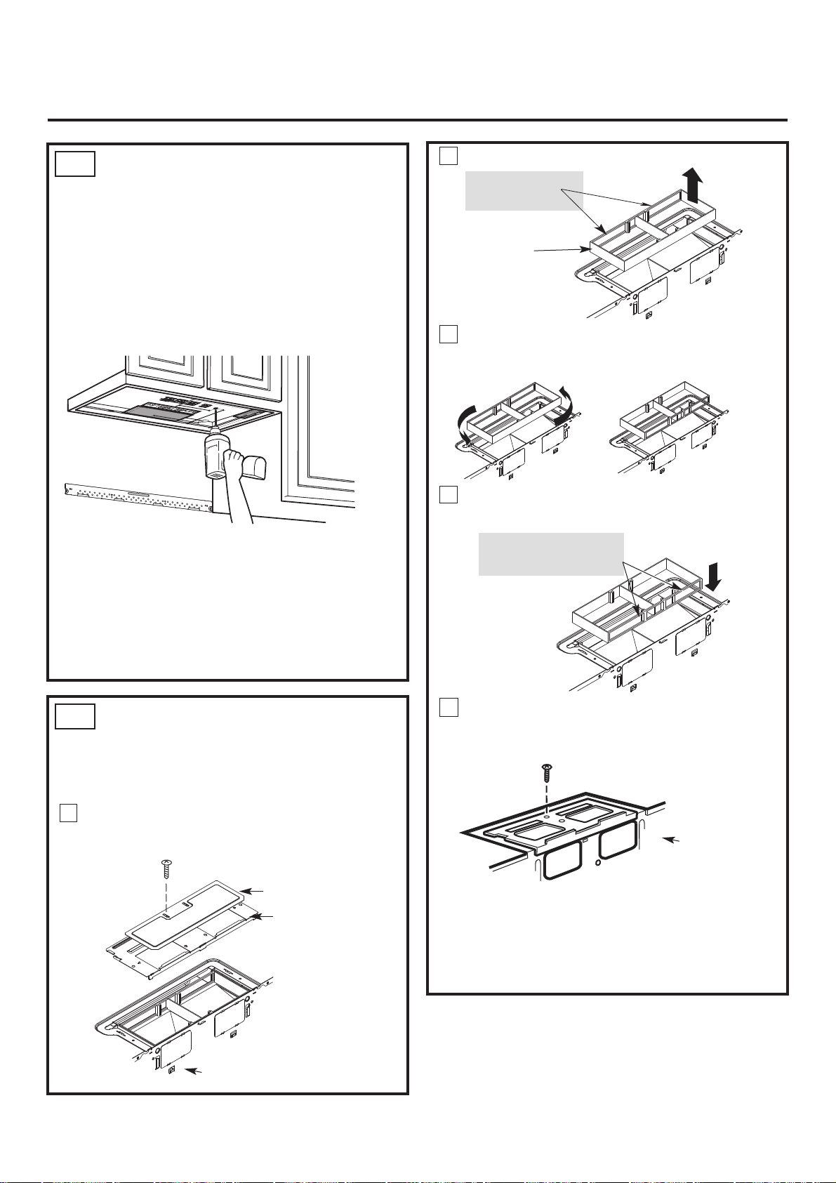
Instrucciones de instalación
C2.
USO DE LA PLANTILLA PARA
EL GABINETE SUPERIOR A FIN
DE PREPARAR EL ÁREA DE
DICHO GABINETE
Es necesario taladrar agujeros para los tornillos de
soporte superior, realizar un agujero lo
suficientemente grande para que el cable eléctuco
pueda pasar a través y recortar también un hueco
to suficientemente amplio para el adaptador de
extracción.
Saque con cuidado el direccionador de aire.
2
Antes:
Aberturas hacia
delante
Direccionador
de aire
Gire el direccionador de aire en sentido
3
contrario a las agujas del reloj 180°.
Antes de la rotación Después de la rotación
Vuelva a colocar el direccionador de aire en la
4
abertura.
• Lea las instrucciones de la sección PLANTILLA
PARA EL GABINETE SUPERIOR.
• Adhiera con cinta la plantilla al gabinete superior.
• Taladre los agujeros, siguiendo las instrucciones de
la sección PLANTILLA PARA EL GABINETE
SUPERIOR.
PRECAUCIÓN: cuando taladre los agujeros en la
superficie inferior del gabinete, use gafas
protectoras.
C3.
AJUSTE DEL VENTILADOR
DEL MICROONDAS PARA LA
EXTRAC- CIÓN SUPERIOR
EXTERNA
Retire el tornillo que sujeta la placa del
1
soplador al microondas. Retire la placa de
cubierta.
Placa de cubierta
Placa del soplador
DESPUÉS: Aberturas del
direccionador de aire
mirando hacia atrás
Vuelva a colocar la placa del soplador con el
5
tornillo retirado en el paso 1. Asegúrese de que
el tornillo esté bien apretado.
Parte trasera del
microondas
Parte trasera del
microondas
ES-20
Page 46
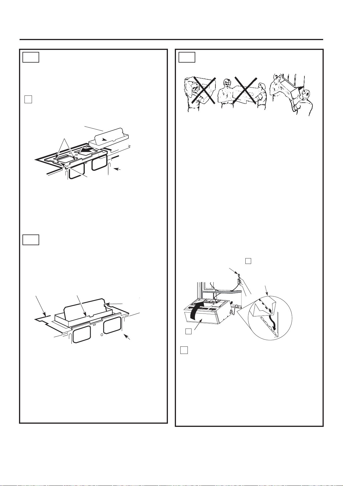
Instrucciones de instalación
C3.
AJUSTE DEL VENTILADOR
DEL MICROONDAS PARA LA
EXTRAC- CIÓN SUPERIOR
EXTERNA (cont.)
6
Vuelva a fijar la placa del ventilador con el
tornillo previa- mente retirado en el paso 1.
Asegúrese de apretar el tornillo.
Guía
Adaptador
Parte trasera del
microondas
Lengüetas de
Bloqueo
Empuje hacia adentro hasta que encaje en las
lengüetas de bloqueo inferiores. Tenga cuidado
de asegurarse de que la bisagra del regulador de
extracción esté instalada de manera que quede
movible libremente.
C3.
VERIFICACIÓN DEL
FUNCIONA- MIENTO
CORRECTO DEL REGULADOR DE EXTRACCIÓN
Placa del
ventilador
Adaptador de
extracción
C5.
INSTALACIÓN DEL HORNO
MICROONDAS
POR RAZONES DE SEGURID PERSONAL Y PARA
FACILITAR LA INSTALACIÓN, SE RECOMIENDA
QUE DOS PERSONAS INSTALEN EL HORNO
MICROONDAS.
IMPORTANTE:No agarre ni use la manija o el
escudo térmico durante la instalación. No retire los
separadores de cartón entre el escudo térmico y la
puerta.
NOTA: si el gabinete es metálico, use una moldura
aislante de nylon alrededor del agujero para el
cable eléctrico, a fin de evitar cortes en el cable.
NOTA: se recomienda el uso de bloques de relleno
si la parte delantera del gabinete sobresale debajo
de la parte inferior del propio gabinete.
IMPORTANTE: Si no se usan bloques de relleno,
pueden producirse daños en la carcasa por apretar
demasiado los tornillos.
NOTA: cuando instale el horno
microondas, ease el cable eléctrico
a través del agujero
correspondiente de la superficie
inferior del gabinete superior
Mantengalo tenso recto durante los
pasos 1 a 3. No permita que el
cable quede atrapado ni levante el
horno tirando del cable.
Levante el microondas, inclínelo
1
hacia adelante y enganche las
ranuras (situadas en el borde
trasero inferior) a las cuatro
lengüetas inferiores de la placa de
instalación.
Regulador de
extracción
Parte trasera
del
microondas
• Antes de instalar el microondas, asegúrese de
que la cinta adhesiva que protege el regulador
de extracción haya sido retirada y que el
regulador se mueve fácilmente.
• Una vez instalado el microondas, necesitará
realizar ajustes para asegurarse de lograr la
alineación correcta con el conducto de
extracción de la cocina.
ES-21
2
Gire la parte delantera del horno
hacia arriba, contra la superficie
inferior del gabinete.
Inserte un tornillo autoalineante a través del
3
agujero del centro del gabinete superior. Fije
temporalmente el horno apretando el tornillo al
menos dos vueltas completas después de due el
tornillo quede enroscado. (Más adelante se
procederá a apretar completamente el
tornillo.)Asegúrese de mantener tenso/recto el
cable eléctrico. Tenga cuidado de evitar que el
cable quede atrapado, especialmente al realizar
la instalación del horno a ras contra la superficie
inferior del gabinete.
Page 47
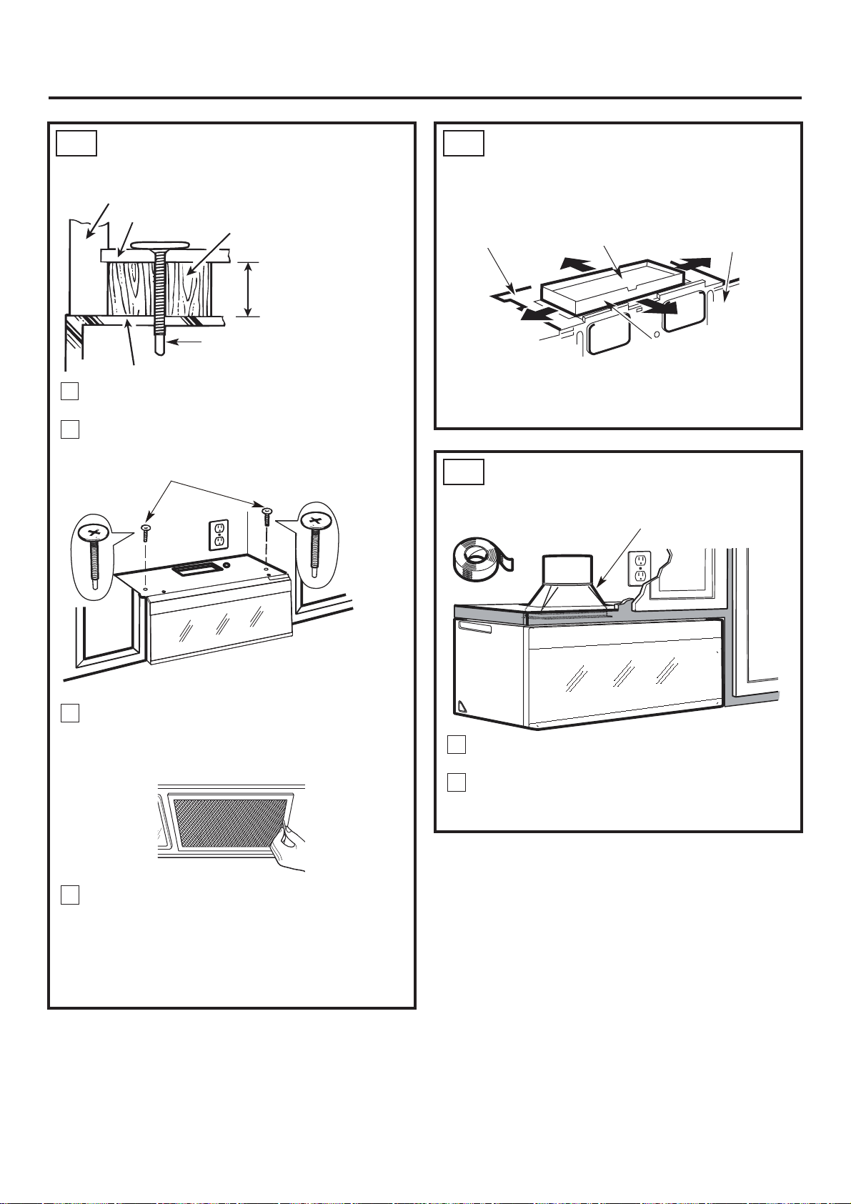
Instrucciones de instalación
C5.
INSTALACIÓN DEL HORNO
MICROONDAS (cont.)
Parte delantera del gabinete
Estante inferior del gabinete
Bloque de relleno
Equivalente a la
profundidad de la
superficie hueca del
gabinete
Tornillo autoalineante
Parte superior del horno microondas
Fije el horno microondas al gabinete superior.
4
5
Inserte 2 tornillos autoalineantes a través de
los agujeros exteriores del gabinete superior.
Apriete cede uno de los tornillos dos vueltas
completas.
C6.
AJUSTE DEL ADAPTADOR DE
EXTRACCIÓN
Abra el gabinete superior y ajuste el adaptador
de Extracción para acoplarlo al conducto de la
cocina.
Placa del ventilador
C7.
ACOPLAMIENTO DEL SISTEMA
Regulador de
extracción
Para ajustes en dirección
delantera-trasera o lado a
lado, deslice el adaptador
de extracción según sea
necesario
Parte trasera
del icroondas
DE CONDUCTOS
Conducto de la cocina
6
Apriete los dos tornillos externos a la parte
superior del horno. (Mientras aprieta los tornillos,
mantenga sujeto el horno contra la pared y el
gabinete superior)
7
Instale los filtros de grasa. Consulte el Manual del
usuario provisto con el microondas.
IMPORTANTE: retire los separadores de cartón
entre el escudo térmico y la puerta
Extienda el conducto de la cocina para que se
1
acople al adaptador de extracción.
Selle las uniones del conducto de escape usando
2
cinta aislante para calefacción para altas
temperaturas.
ES-22
Page 48
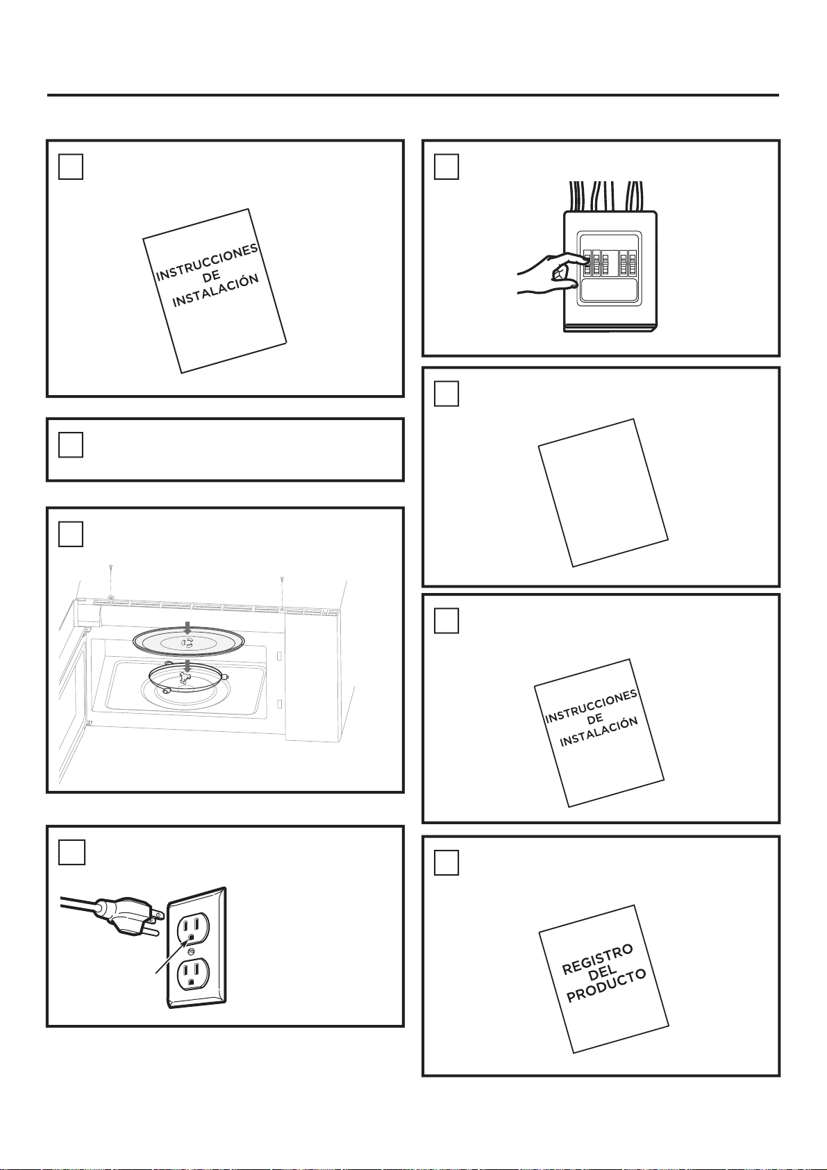
Instrucciones de instalación
ANTES DE USAR EL HORNO MICROONDAS
Asegúrese de que el horno microondas haya
1. 5.
sido instalado según las instrucciones.
6.
2.
Retire todo el material de empaque del horno
microondas.
3.
Instale el anillo y el plato giratorio en el
interior del horno.
Vuelva a colocar el fusible correspondiente o
encienda de nuevo el disyuntor.
Lea el manual de use y cuidado.
GUÍA DE USO
Y CUIDADO
Conecte el cable de alimentación a un
4.
tomacorriente exclusivo (dedicado) de 15 a
20 amperios.
Antes de usar el
electrodomestico
verifique la
puesta a tierra
del tomacorriente
CONSERVE LAS INSTRUCCIONES DE
7.
INSTALACIÓN PARA USO DEL INSPECTOR
LOCAL.
LIENE LA TARJETA DE REGISTRO DEL
8.
PRODUCTO.
ES-23
Page 49
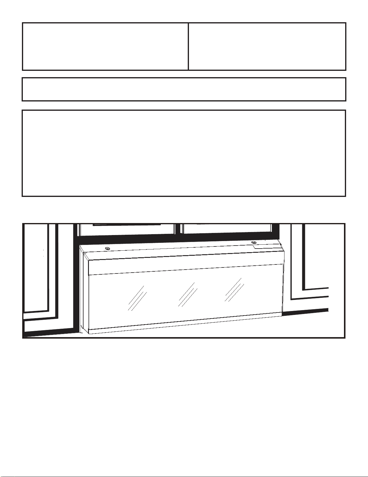
Instructions
Four à micro-ondes
d’installation
Des questions? Appelez au 1-800-944-9044(US) ou 1-800-265-8352(Canada)
à hotte intégrée
AVANT DE COMMENCER
Lisez attentivement toutes ces instructions.
IMPORTANT– Conservez ces instructions
•
pour l’inspecteur local.
•
IMPORTANT– Respectez tous les codes et
règlements en vigueur.
• Remarque destinée à l’installateur – Assurezvous de laisser ces instructions au
consommateur.
•
Remarque destinée au consommateur–
Conservez ces instructions pour vous y reporter
ultérieurement.
• Niveau de compétence – L’installation de cet
appareil nécessite des compétences de base en
mécanique et en électricité.
• L’installateur est responsable de la qualité de l’installation.
• Une panne causée par une mauvaise installation
n’est pas couverte par la garantie du produit.
VEUILLEZ LIRE ATTENTIVEMENT.
CONSERVEZ CES INSTRUCTIONS.
p/n A06823451
Août 2022
Page 50

Page 51
Instructions d’installation
INDEX
Renseignements généraux
Mesures de sécurité importantes..........................3
Exigences électriques.............................................. 3
Dommages - Expédition/installation...................4
Pièces comprises ...................................................... 4
Outils nécessaires..................................................... 5
Dégagements pour l’installation...........................5
Guide d’installation étape par étape
Installation de la plaque de montage...............6-8
Enlèvement de la plaque de montage..............6
Localisation des montants ....................................6
Établissement de l’emplacement de la plaque
murale............................................................................7
Évacuation à l’extérieur par le
C
dessus........................................................19-22
Fixation de la plaque de montage au
mur.........................................................................19
Préparation de l’armoire supérieure.........20
Ajustement du ventilateur........................20-21
Vérification du fonctionnementdu
registre......................................................................21
Installation du four à micro-ondes........21-22
Ajustement de l’adaptateur
d’évacuation..........................................................22
Connexion au conduit.......................................22
Avant d’utiliser votre four à
micro-ondes..........................................................22
L`information de gabarit .....................................23
Alignement de la plaque murale ......................8
Types d’installation ..................................................9
Recyclage d’air.........................................10-12
A
Fixation de la plaque de montage au
mur........................................................................10
Préparation de l’armoire supérieure.........11
Vérification de l’plaque du ventilateur....11
Installation du four à micro-ondes...... 11-12
Installation ou changemeut du filtre à
charbon.....................................................................12
Évacuation de la hotte .....................................13-14
Évacuation à l’extérieur par l’arrière.15-18
B
l’évacuation à l’extérieur par
l’arrière...............................................................15
Enlèvement de l’plaque du
ventilateur.........................................................15
Fixation de la plaque de montage au mur.. ...16
Préparation de l’armoire
supérieure.........................................................16
Adaptation du ventilateur du four à
micro-ondes pour l’évacuation à
l’extérieur par l’arrière.............................16-17
Installation du four à
micro-ondes.....................................................18
FR-2
Page 52
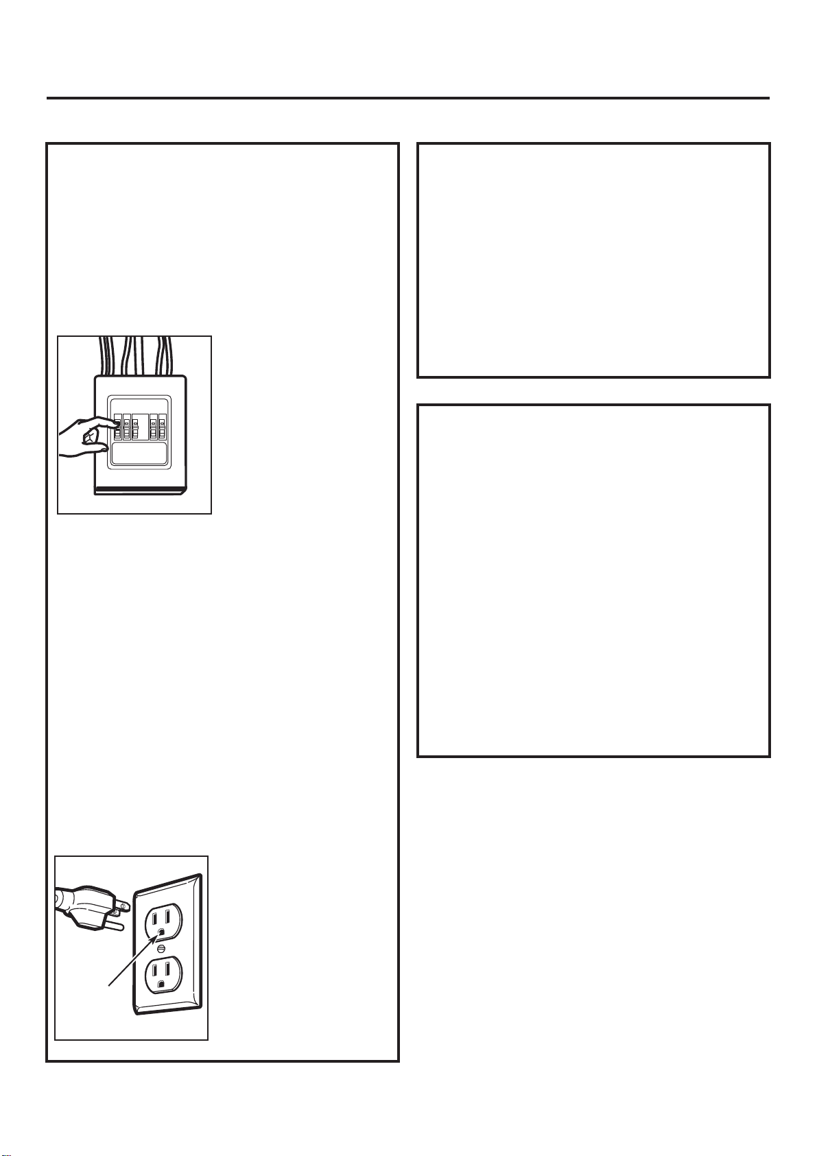
Instructions d’installation
MESURES DE SÉCURITÉ IMPORTANTES
Ce produit nécessite une prise de courant à trois
alvéoles mise à la terre. Avant d’entreprendre
l’installation, l’installateur doit vérifier la continuité
de la mise à la terre de la boîte de la prise de
courant pour s’assurer que cette dernière est
correctement mise à la terre. Si ce n’est pas le cas,
ou si la boîte ne répond pas aux exigences
électriques indiquées (à la section EXIGENCES
ÉLECTRIQUES), il faut faire appel à un électricien
qualifié pour corriger tout
défaut.
ATTENTION: Pour votre
sécurité, enlevez le fusible
ou déclenchez le
disjoncteur au panneau de
distribution principal
avant d’entreprendre
l’installation, afin d’éviter
toute blessure grave ou
mortelle imputable à un
choc électrique.
ATTENTION : Pour votre sécurité, la surface de
montage doit être en mesure de supporter la
charge des armoires, ainsi qu’un poids
supplémentaire de 28,5 à 38,5 kg (63 à 85 lb)
correspondant au poids du produit, et la charge du
four qui peut atteindre 22,7 kg (50 lb), pour un
poids total de 51,3 à 61,2 kg (113 à 135 lb).
ATTENTION : Pour votre sécurité, ce produit ne
doit pas être installé avec des armoires aménagées
en îlot ou en péninsule. Il doit être fixé À LA FOIS à
une armoire supérieure ET à un mur.
REMARQUE : Pour faciliter l’installation et pour
votre sécurité, l’installation de ce produit doit être
effectuée par deux personnes.
IMPORTANT – VEUILLEZ LIRE ATTENTIVEMENT.
POUR VOTRE SÉCURITÉ, CET APPAREIL DOIT
ÊTRE
CORRECTEMENT MIS À LATERRE POUR ÉVITER
UN CHOC GRAVE OU MORTEL.
Demandez à un électricien qualifié de vérifier la
prise murale et le circuit électrique pour vous
assurer que la prise est correctement mise à la
terre.
Si la prise murale est du type standard à deux
alvéoles, il est très important de la faire remplacer
par une prise à trois alvéoles correctement mise à
la terre en vous adressant à un électricien qualifié.
NE COUPEZ, NE DÉFORMEZ ET NE RETIREZ EN
AUCUN CAS UNE DES BROCHES DE LA FICHE DU
CORDON D’ALIMENTATION. N’UTILISEZ PAS DE
RALLONGE.
EXIGENCES
ÉLECTRIQUES
Les caractéristiques nominales de ce produit sont :
120 V CA, 60 Hz, 15 A et 1,6 kW. Ce produit doit être
branché à un
circuit d’alimentation séparée et dédiée de tension
et de fréquence appropriées. La grosseur des fils
doit être conforme aux exigences du Code national
d’électricité ou du code local en vigueur pour cette
puissance nominale. La fiche du cordon
d’alimentation doit être branchée dans une prise de
courant mise à la terre, séparée et dédiée de 15 ou
20 ampères. La boîte de la prise doit être aménagée
dans l’armoire située au-dessus du four à
micro-ondes. La boîte de la prise et le circuit
d’alimentation doivent être installés par un
électricien
qualifié, conformément aux normes du Code
national d’électricité ou du code local en vigueur.
Assurez-vous
qu’une mise à
la terre
appropriée est en
place avant toute
utilisation
Pour diminuer les risques
de choc électrique, le
cordon d’alimentation de
cet appareil est muni
d’une fiche à trois broches
(mise à la terre) qui
correspond à une prise
murale à trois alvéoles,
mise
à la terre.
FR-3
Page 53
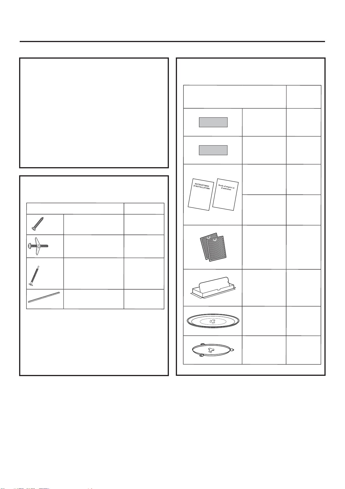
Instructions d’installation
DOMMAGES — EXPÉDITION/
INSTALLATION
• Si l’appareil est endommagé durant le transport,
retournez-le au magasin où vous l’avez acheté
pour réparation ou remplacement.
• Si l’appareil est endommagé par le client, la
réparation ou le remplacement reste à la charge du
client.
• Si l’appareil est endommagé par l’installateur (s’il
s’agit d’une personne différente du client), la
réparation ou le remplacement doivent faire l’objet
d’une entente entre le client et l’installateur.
PIÈCES COMPRISES
SACHET DE QUINCAILLERIE
PIÈCE QUANTITÉ
PIÈCES COMPRISES
SACHET DE QUINCAILLERIE
PIÈCE QUANTITÉ
Vis à bois (1/4 x 2 po)
2
Gabarit pour
armoire
supérieure
Gabarit po ur
mur arriére
combiné
Instructions
d’installation
Mode d’emploi
et d’entretien
(SUITE)
1
1
1
1
Boulons à ailettes (et
écrous à oreilles)
(3/16 x 3 po)
Vis à métaux à
auto-alignement
(1/4 po - 28 x 3
po)
Passe-fil en nylon
(pour armoires en
métal)
Vous trouverez les pièces de quincaillerie dans
un sachet fourni avec l’appareil. Vérifiez que
vous avez reçu toutes ces pièces.
REMARQUE: Des pièces supplémentaires sont
incluses.
1/4"
2
3
1
Filtres à
graisses
emballés
séparément
Adaptateur de
conduit
d’évacuation
Plateau en
verre
Anneau de
plateau
tournant
2
1
1
1
FR-4
Page 54
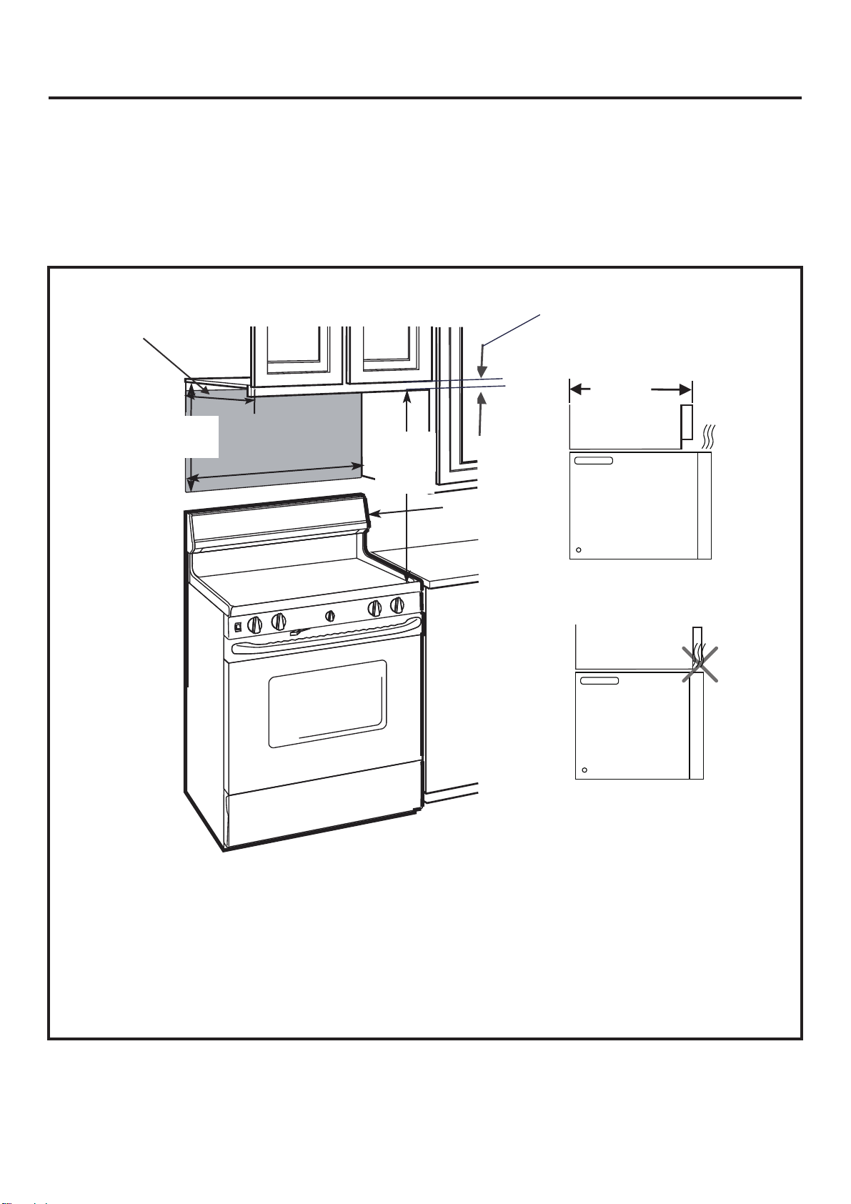
Instructions d’installation
OUTILS NÉCESSAIRES
• Mètre
• Scie trépan
• Trouveur de goujons ou marteau
• Niveau
• Ruban adhésif et de masquage
• Ciseaux
DÉGAGEMENTS POUR L’INSTALLATION
13,8" Max
(35 cm)
10,3
"
(26,2cm)
"(7
30
6,
2c m
• n #1 tournevis cruciforme
• Perceuse électrique
• Foret 3/16 ’’, 1/2 ’’, 5/8 ’’
• Blocs de bois de remplissage pour armoires
à fond encastré
• Cisailles
¼" Min
gagement
13,8" MAX.
(35 cm)
"
)
24
(61cm)
min.
Dosseret
Armoire
Armoire
• Il faut un espace d au moins 30 po (76,2 cm) entre les armoires, sans obstructions.
• Si l’évacuation de l’air de votre four à micro-ondes s’effectue vers l’extérieur, consultez la section
« Évacuation de la hotte pour la préparation du conduit d’évacuation ».
• Lorsque vous installez le four à micro-ondes sous des armoires dont le fond est lisse et plat, suivez
attentivement les instructions du gabarit pour armoire supérieure concernant le d gagement du cordon
d’alimentation.
• Comme un guide d’installation, voir page 26 pour l information de gabarit montage.
• Si la profondeur du armoire incluant les portes du armoire est plus de 13,8 po alors l'unité doit être espacée
du mur utilisant des matériaux adéquats supportant 150 lbs pour permettre une bonne ventilation d'air au
sommet/ admission d'air.
FR-5
Page 55
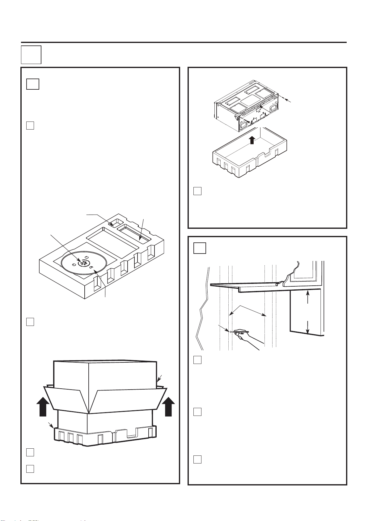
Instructions d’installation
INSTALLATION DE LA PLAQUE DE MONTAGE
1
ENLEVER LE FOUR À
A
.
MICRO-ONDES DU
CARTON/ENLEVER LE
PLATEAU DE MONTAGE
Enlevez les instructions de l'installation,
1
utilisez et prenez soin, adaptateur
d'échappement, anneau de la plaque
tournante, rayon, filtres, plateau de verre et le
petit sac de matétiel. N'enlevez pas le
polystyrène protégeant l'avant du four. Gardez
l'appareil à au moins 8 pouces du bord
supérieur du comptoir pour éviter qu'il ne
tombe à cause de la lourde porte.
Petit sac de matériel
Anneau de la plaque
tournante sous le
plaeau de verre
Adaptateur
d'échappement
Plaque de montage
Vis
Enlevez les vis de la plaque de montage. Cette
5
plaque sera utilisée comme gabarit pour le
mur arrière et pour le montage. Remettez en
place les vis retirées
préalablement.
Vis
Plateau de verre
Repliez complètement les quatre rabats contre
2
les côtés de la boîte. Ensuite, retournez le four
et la boîte avec précaution. Le four devrait
reposer sur le polystyrène.
Polystyrè
ne
Tirez la boîte vers le haut pour dégager le four.
3
Coupez le centre du sac en plastique pour retirer
4
la plaque de montage
Boîte
LOCALISATION DES
B.
MONTANTS
Montants
(26,2cm)
Centre
Localisez les montants en utilisant une des
1
méthodes suivantes :
A. Localisateur de montant – dispositif magnétique
permettant de localiser les clous.
B. Utilisez un marteau pour frapper légèrement sur
la surface de montage jusqu’a ce que vous
n’entendiez plus un son creux. Cela signifie que
vous avez trouvé un montant.
Après avoir localisé le(s) montant(s), trouvez-en
2
le centre en sondant le mur à l’aide d’un petit
clou afin de trouver les rebords du montant. Puis
faites une marque à mi-chemin entre les deux
bords. Le centre de tout montant adjacent doit
se trouver à 16 po (40,6 cm) ou 24 po (61 cm)
de cette marque.
Tracez une ligne verticale marquant le milieu des
3
montants.
LE FOUR À MICRO-ONDES DOIT ÊTRE FIXÉ À AU
MOINS UN MONTANT DU MUR.
FR-6
10.3
"
Page 56
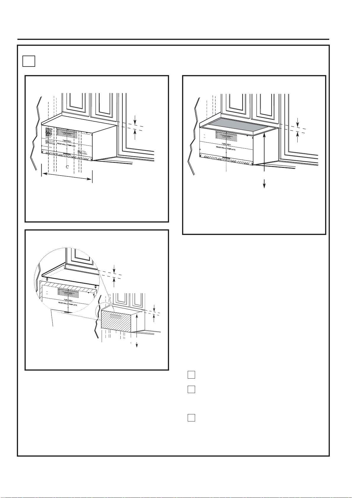
Instructions d’installation
3
/8"
TO
E
D
G
E
N
O
TE:
I
T
IS
VE
R
Y
I
MP
OR
T
A
N
T
T
O
REA
D
A
N
D
F
O
L
LOW
TH
E
D
IRECTIONS
I
N
T
H
E
IN
S
T
A
LL
A
T
IO
N
IN
S
TR
U
CT
I
O
N
S
B
E
FO
RE P
R
O
CEED
I
NG
W
I
T
H
T
H
I
S
R
E
A
R WA
L
L
T
E
MP
L
AT
E.
This
R
e
ar
W
all Tem
p
la
t
e s
er
v
e
s
to p
os
it
i
o
n
the
b
o
t
to
m
mo
u
nting
pla
te
a
n
d
to l
o
c
at
e
th
e ho
riz
on
ta
l e
xha
ust
outle
t.
1
. U
s
e a
l
ev
el
to
c
heck
th
at
th
e
te
mp
la
t
e is
p
o
sit
i
o
ne
d
a
c
c
u
r
at
e
ly
.
2
.
Loca
te
and
ma
r
k
a
t le
a
s
t
o
n
e st
u
d
o
n t
he
left
o
r
r
i
g
ht
s
id
e
o
f
th
e c
e
nte
r
l
ine.
It is
i
mpo
rtan
t t
o
us
e a
t le
a
s
t
o
n
e
w
ood
s
c
r
e
w
mo
un
t
ed firmly in
a
s
tu
d
t
o
su
ppo
rt the
w
e
ig
h
t
o
f
th
e
micr
ow
av
e
.
Ma
rk t
w
o
a
dditio
nal,
e
v
enly
s
p
ace
d
loc
a
tion
s fo
r
the
s
upp
l
i
ed t
og
gle bol
ts.
3. D
r
ill holes in
t
he ma
rke
d
lo
c
ation
s. Whe
re th
er
e is
a
stud
, d
rill
a 3
/1
6
"
h
o
le
fo
r w
o
od
s
c
rews
.
For
h
oles
t
h
a
t do n
ot line
up
with a s
tud
,
d
r
ill
5
/8
" h
o
les fo
r
toggle
bo
lts.
D
O N
OT INS
TAL
L
TH
E
MO
U
N
TIN
G PL
ATE
AT TH
I
S TI
M
E
.
4.
Re
m
ov
e
the
te
mpla
te
fr
om t
he
rea
r
w
all.
5
.
Re
v
ie
w
t
he
In
s
t
allatio
n
In
s
tru
c
t
io
n
bo
o
k fo
r
y
ou
r
in
sta
llatio
n
s
itu
a
tio
n.
L
o
ca
t
e an
d
ma
r
k
h
o
l
e
s
to a
l
ig
n
w
it
h
h
ol
e
s
i
n
th
e
mo
u
n
t
i
ng
p
la
t
e.
IM
P
OR
T
A
N
T
:
LO
C
AT
E
AT
LE
A
S
T
ON
E
S
T
U
D
O
N
E
I
TH
E
R
SI
DE
OF
TH
E
C
E
NTE
RL
I
NE.
M
AR
K T
HE L
OC
A
TI
O
N
FO
R
2
A
D
D
I
T
I
ON
A
L
,
E
VEN
L
Y
SP
A
C
ED
TOGGLE
B
O
L
T
S
I
N
T
H
E
M
O
UNT
I
N
G
PL
AT
E
AR
E
A.
Lo
cate
a
n
d
mar
k
h
o
l
e
s
t
o
a
l
i
gn
w
i
t
h
h
ol
e
s
in
t
he
m
o
untin
g
pl
a
t
e
.
I
M
PO
R
T
A
NT:
L
OC
A
TE
A
T
L
E
A
S
T
ON
E ST
U
D
O
N
EI
T
H
ER
S
IDE
O
F
T
H
E
C
E
N
T
E
R
LI
NE
.
M
AR
K
T
HE
LOCA
TI
O
N
F
O
R
2
A
D
D
IT
IONAL
,
EVEN
LY
S
PA
C
E
D
T
O
G
GL
E
BOL
T
S
I
N
T
H
E
M
O
UN
T
A
R
EA
.
Tri
m
t
he
r
ea
r
wa
ll
t
empl
at
e
a
l
ong
th
e
do
t
ted
lin
e
.
T
r
i
m
t
h
e
r
ea
r
w
al
l
te
m
pl
a
t
e
a
l
o
n
g
the
do
tted
li
n
e.
12
"
4"
D
a
rl
e
v
ue
l
t
a
a
l
a
ho
ja
para
co
n
s
u
l
t
ar
l
a
ve
rsi
n
e
n
E
s
paæ
o
l
.
ÉTABLISSEMENT DE L’EMPLACEMENT DE LA PLAQUE MURALE
C.
SOUS VOTRE ARMOIRE
Emplacement de la plaque - sous une armoire à
fond plat
1/4"
Min gagement
Au moins 30 po
Tracez une ligne verticale sur le mur au centre
de l'espace de 30 po de large.
Tape gabarit pour mur arrière sur le mur
correspondant à la ligne médiane et en touchant
le bas de l'armoire.
Emplacement de la plaque - sous une
1/4"
Min gagement
1/4"
overhang
Tracez une ligne sur
le mur arrière égale à
la profondeur de le
surplomb avant
N
OT
E
: I
T
IS
V
R
ER
E
A
Y
D
I
MP
A
ND
O
F
RT
O
IN
AN
LL
TH
T T
O
E I
W
O
T
N
HE
S
T
A
D
B
L
E
IR
L
FO
AT
E
C
R
I
O
TI
E P
N
O
I
N
R
N
S
O
STR
R
CE
E
A
U
E
R
C
D
W
T
I
N
I
A
O
G
LL
N
W
S
Th
T
IT
is
E
H
M
R
e
PL
T
ar
H
W
A
3
IS
/8
al
TE.
"
l
Te
m
TO
o
m
u
E
n
p
DG
tin
l
at
E
g
e
plat
se
r
e
v
e
o
an
s
u
tl
to
d
et.
t
p
o
o
lo
sit
12"
c
i
a
o
t
n
e
t
t
h
he
1.
e
b
Use
h
o
o
t
r
t
o
i
zo
a
m
n
l
ev
ta
l
e
e
l
xh
t
o
a
c
a
u
he
c
s
cu
t
c
k
r
t
a
h
te
a
l
t
y.
t
h
e
2
t
.
e
L
mpla
oc
a
t
te
e
an
i
s
d
p
o
m
s
ar
it
i
rig
k a
on
h
e
t
t
d
l
s
e
i
d
a
s
e
t
of
o
n
t
e
h
e
st
c
u
e
d
nte
o
n
r
l
t
i
h
n
I
e
e
t
4
.
is
le
"
f
im
t
o
p
r
s
o
c
rt
re
a
w
nt
m
t
o
ounted
u
s
e
a
o
t
f
f th
l
i
e
r
m
a
e
s
l
y
t
mi
o
i
n
n
c
a
e
r
ow
stu
w
oo
a
d
v
l
d
o
e.
t
o
c
a
M
s
t
u
io
ark
pp
ns fo
o
t
w
r
t
o
r
the
t
a
h
d
e
3
w
d
.
s
iti
e
u
D
i
o
ppli
g
r
n
ill
h
a
t
h
l
e
,
o
d
e
l
v
es
t
o
e
g
n
in
gle
ly
t
s
he
b
pa
a
ol
m
st
ce
t
s
ark
u
d
.
d
, d
e
d
ri
l
l
l
a
3
/
that
1
d
o
n
o
t
li
ne
t
u
o
gg
le
bol
ts
.
D
O
NOT
A
T
I
N
T
H
I
S
T
IM
E
.
4.
R
e
m
o
v
e
t
h
e
t
5
e
. R
m
e
v
i
e
w t
he
Ins
i
tal
n
s
t
a
lla
t
i
o
n
s
i
t
u
a
t
Da
r
le
v
ue
l
t
a a
v
l
a
e
r
h
s
i
n
en
E
sp
a
æ
L
o
cat
e
a
n
d
m
ar
m
o
u
n
t
i
n
g
p
l
a
t
I
MPO
R
T
A
NT
:
L
O
CA
T
E
A
T
L
T
H
E
C
E
N
T
E
R
M
A
R
K
T
HE
L
O
SP
A
C
E
D
TO
G
ARE
A
.
Tr
im
th
e
r
ear
w
a
l
l
t
e
m
p
l
at
e
Tr
oc
a
im
t
i
o
ns
6
"
ho
l
e
f
or
p
w
i
t
h
a
s
t
ud
S
TA
LL
T
H
p
la
te
f
r
o
m
t
la
t
io
n
Ins
t
ru
i
o
n
.
o
j
a
p
a
r
a c
o
l.
k
h
o
l
e
e
.
E
A
S
T
ON
LI
N
E.
C
A
T
IO
GL
E
B
OL
al
o
n
g
t
h
th
.
W
e
he
r
re
ea
t
w
h
o
od
s
,
dr
i
ll
E
MO
h
e
r
e
a
c
t
io
n b
o
n
s
u
s
t
o
a
E
S
N
F
O
T
S
e
d
o
r
e
w
re
al
is
c
re
ws
.
5
/8
"
h
UNT
IN
r wa
l
l.
oo
k
f
o
lta
r
la
li
g
n wit
T
U
D ON
R
2
I
N
T
t
t
e
d
l
te
F
or
h
o
le
s
fo
G P
L
ATE
r
y
o
ur
h
h
A
D
D
H
E
M
l
i
ne.
mp
l
a
o
le
s
r
ole
s
i
E
I
T
H
E
IT
I
O
N
OUNTING
t
e
alo
n
g
t
h
e
d
o
t
t
e
d
l
i
n
e
n
t
he
R
S
IDE
O
F
A
L,
E
VE
NL
Y
P
L
A
T
E
.
Lo
c
ate
a
n
d
ma
r
k
moun
h
o
l
es
ti
n
t
o
g
a
p
lign
l
at
e
.
w
i
IM
th h
PO
o
l
RTA
es
i
n
N
t
T
h
:
e
LO
C
A
T
E
AT
L
EA
T
ST
H
E
O
C
N
E
E
NT
S
ER
T
U
D
L
I
ON
NE
MA
.
R
E
K
I
TH
T
H
E
E
R
L
SIDE OF
OC
S
A
P
TI
AC
O
N
E
F
D
O
T
R
O
G
2
G
A
A
L
D
E
R
D
E
I
BO
TIO
A
.
L
T
NA
S
L
IN
,
E
T
V
H
ENL
E M
Y
O
U
N
T
I
N
G
P
LAT
E
C
À 24 po de la surface de cuisson
Min
gagement
Emplacement de la plaque - sous une armoire
dotée d’un rebord
1/4"
Min gagement
NOT
E
:
I
T
IS
V
E
RE
R
Y
A
D
I
MP
A
N
O
D
R
F
T
O
A
IN
N
LLO
T
THE
T
W
O
T
I
N
HE
STA
DI
L
BE
RE
L
A
F
CT
TI
OR
ON
I
ONS
E
I
P
N
R
S
O
T
R
CEED
RUC
E
AR
T
I
I
W
N
ON
G
A
L
S
W
L
IT
T
E
T
MP
h
i
s
R
LA
e
a
TE
r
Wa
.
l
l
T
mo
e
mp
un
l
t
at
i
n
e
g
s
p
e
l
a
r
ve
t
e
s
a
o
n
t
ut
o
d
l
p
et
t
o
o
.
si
l
o
t
c
at
e
t
h
e
1
h
.
or
Use
i
z
o
n
a lev
e
l
t
o
ch
a
e
c
ck t
c
ur
h
a
at
t
el
t
y.
h
e
t
e
2
m
.
L
p
oc
la
te
a
te
a
n
d
m
a
r
k
r
i
g
a
h
t l
t
e
s
a
i
de
st
o
o
n
f
e
th
s
e
t
ud
c
ente
o
n t
r
l
in
e
I
.
t
is
i
mp
o
sc
r
ta
re
nt
w
t
m
o u
ou
se
n
t
ed
a
t
lea
f
o
i
r
f
ml
s
the
t
y
o
i
n
m
n
i
a
cr
s
o
t
w
u
d
a
to
v
e
l
o
.
s
cati
M
u
p
a
o
p
rk
o
n
s
tw
fo
o
r
a
t
d
h
d
e
i
3
t
su
i
.
on
Dr
ppl
al
i
ll
,
i
ed
e
h
ol
t
e
o
s
g
g
in
le
t
he
bol
a
m
t
s
s
.
ar
t
u
ke
d
,
d
d
lo
r
i
ll
ca
a
t
3/
io
1
n
t
6
s. Wh
h
"
a
t
h
d
o
o
l
e
n
f
o
o
r
t
l
w
in
o
e
to
o
u
d
p
scr
g
w
g
i
l
e
t
e
h
bo
a
s
lt
t
s
u
.
d
,
d
r
i
l
l
5
/
8
D
O
NO
T
A
INST
T
T
H
AL
I
S
L
T
IM
TH
E
E
.
4
M
.
O
R
U
e
N
mo
ve
t
h
e
t
e
5
mp
.
R
e
l
ate
v
i
e
w
f
r
o
t
he
m
t
h
I
n
e
st
r
al
e
i
nstal
a
l
a
r
ti
wa
o
la
n
t
I
i
n
o
st
n
r
s
u
i
ct
t
u
io
a
t
n
i
o
b
n
o
.
o
Darle vu
e
lt
a
a
la
vers
h
oja
i
ó
n
p
e
a
n
r
a
E
c
s
on
pañ
s
u
o
l
l
t
.
a
bottom
r
L
oc
a
t
e
an
d
ma
rk
h
mo
o
l
es
u
nt
t
i
o
n
g
a
l
p
i
g
l
a
te.
I
MP
O
R
T
AN
T
:
LO
C
A
TE
A
T
LEA
S
T
T
H
O
E
NE
C
E
N
S
T
T
E
UD
R
L
IN
MAR
E
.
K
T
HE
L
OCA
S
TI
P
O
A
CE
N
F
D
O
T
R
O
G
G
LE
A
R
B
E
OLT
A
.
S
I
N
T
r
im
the
rear wal
l
temp
l
a
te
a
lo
n
g
t
h
e
do
t
te
3/
H
8"
TH
I
i
o
n th
e
b
t
a
l
exh
a
i
s
p
o
sit
i
he
l
e
f
t
o
e
w
o
od
r
t
t
h
e
w
ei
v
en
l
y
spa
e
r
e
t
h
e
w
s.
F
o
r
"
h
ol
e
s
TING
P
LA
l
l
.
k
f
o
r
yo
la
n
wi
t
h
ON
2
A
D
DI
T
H
E
d
lin
e
TO
ED
S
GE
12"
o
t
t
o
m
u
s
t
on
e
d
4
"
r
ght
ced
re
is
h
oles
f
o
r
T
E
ur
h
o
l
e
s
i
n
t
he
E
I
T
H
ER
S
I
DE
O
F
T
IONA
L
,
E
V
E
NLY
MO
UN
T
ING PL
A
TE
.
T
rim
t
h
e
r
ear w
a
l
l
te
mp
l
a
t
e
a
l
on
g
t
h
e
do
tt
e
d
li
n
e
.
L
oc
a
t
e
a
nd
ma
rk h
mou
o
l
e
s
n
t
t
i
o
ng
a
p
l
i
gn
l
a
t
e
w
.
i
t
h
IM
ho
P
l
e
O
s
RT
in
t
A
h
NT:
e
L
OCA
T
E
A
T
L
E
AST
T
HE
ONE
C
E
NT
S
T
E
UD ON
R
L
I
N
MA
E
.
EI
RK
TH
T
E
H
R
E
S
LO
I
D
E
C
O
A
S
TI
F
PA
ON
C
E
F
D T
OR
O
2
G
A
G
DD
LE
A
I
R
T
B
EA
I
O
O
NA
L
.
TS
L
,
IN
E
V
THE
E
N
L
MOUNTI
Y
N
G
PL
AT
E
C
À 24 po de la surface de cuisson
Tracez une ligne verticale sur le mur au centre
de l'espace de 30 po de large.
Tape gabarit pour mur arrière sur le mur
correspondant à la ligne médiane et en touchant
le cadre bas de l'armoire.
Vos armoires peuvent être dotées de
garnitures décoratives qui entravent
l’installation du micro-ondes. Enlevez
l’élément décoratif pour installer
convenablement le four à micro-ondes et
pour vous assurer qu’il est de niveau.
LE FOUR À MICRO-ONDES DOIT ÊTRE DE
NIVEAU.
Utilisez un niveau pour vous assurer que le
fond de l’armoire est de niveau.
Si les armoires sont dotées uniquement
d’un rebord avant, sans rebord sur les
côtés ou à l’arrière, installez la plaque de
montage plus bas, à la même distance que
le rebord avant de l’armoire. Ainsi, le four
sera de niveau.
Mesurez la hauteur intérieure du rebord avant
1
de l’armoire.
Tracez une ligne horizontale sous le fond de
2
l’armoire, sur le mur arrière à une distance
équivalente à la longueur intérieure du rebord
avant de l’armoire.
Pour l’installation sous une armoire dotée d’un
3
rebord avant uniquement, alignez les
languettes de montage sur cette ligne
horizontale, sans qu’elles touchent le fond de
l’armoire, tel que décrit à l’étape D.
FR-7
Page 57
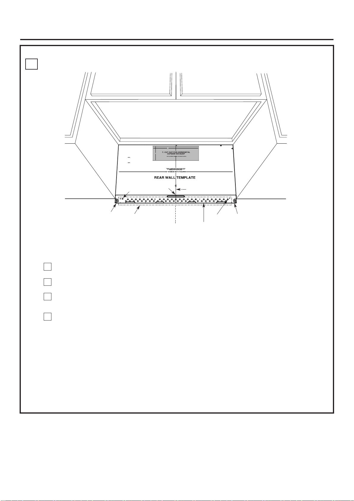
Instructions d’installation
D.
ALIGNEMENT DE LA PLAQUE MURALE
NOTE: IT IS VERY IMPORTANT TO
READ AND FOLLOW THE DI
IN THE INSTALLATION INSTRUCTIONS
BEFORE PROCEEDI
REAR WALL TEMPLATE.
This Rear Wall Template serves t
mounting plate and to locate the horizontal exhaust
outlet.
1. Use a level to check th
accurately.
2. Locate and ma
rk at least one stud on the left or
right side of the centerlin
It is important to use at least one wood
screw mounted firmly in a stud to s
of the microwave. Mark two add
locations for the supp
3. Drill holes in the marked locatio
a stud, drill a 3/16" hole for
that do not line up with a st
toggle bolts.
DO NOT INSTALL THE M
AT THIS TIME.
4. Remove the template from the rear wall.
5. Review the Installation Instru
installation situation.
Darle vuelta a la hoja para consultar la
versión en Español.
Locate and mark
mounting plat
e.
IMPORTANT:
LOCATE
AT LEAST ONE
THE CENTERLINE.
MARK THE LOCATION FOR 2
SPACED
TOGGLE BOLTS IN THE MOUNTING PLATE
AREA.
Trou B
at the template is positioned
lied toggle bolts.
holes to align with h
e.
NG WITH
itional, evenly spaced
wood screws. For hole
ud, drill 5/8" holes for
ction book for your
o position the bottom
upport the weight
ns. Where there is
OUNTING PLATE
RECTIONS
THIS
s
oles in the
STUD ON EITHER SIDE OF
ADDITIONAL, EVENLY
12"
4"
Encoches de la
ligne centrale
3/8" TO EDGE
Locate and mark
mounting plate.
IMPORTANT:
LOCATE
AT LEAST ONE
THE CENTERLINE.
MARK THE LOCATION FOR 2
SPACED
TOGGLE BOLTS IN
Tracez une ligne verticale sur le
mur du Centre d`armoire
supérieure
AREA.
Trim the rear
holes to align with hol
wall template al
es in the
STUD ON EITHER SIDE OF
ADDITIONAL, EVENLY
THE MOUNTING PLATE
ong the dotted
line.
La ligne horizontale
Tracez une ligne verticale sur le mur au
1
Zone E
centre de l’espace de 30 po de large.
Tracez une ligne horizontale sur le mur de
2
fond de "Gabarit pour mur arrière".
Trouvez un clou du mur dans la zone "E"
3
du plateeau de montage, reférez-vous à la
section 1B. Trouver les clous du mur.
Pour attacher le plateau du montage dans
4
le clou forez un trou de 3/16 po dans le
clou en bois. Forez un trou de 5/8 po pour
le verrou d'interrupteur à bascules dans un
autre emplacement (Trou A ou Trou B).
REMARQUE : NE FIXEZ PAS LA PLAQUE
DE MONTAGE MAINTENANT.
Trou A
C
Tracez une ligne horizontale sur le mur de fond
de "Gabarit pour mur arrière"
L
La ligne horizontale
REMARQUE: Les trous A et B sont à l'int rieur de la
zone E. Si aucun des trous A et B ne se trouve
dans un montant, trouvez un montant dans la zone
E et tracez un cinquième cercle pour l’aligner sur
un montant. Il est important qu’au moins une vis à
bois soit fixée solidement dans un montant pour
soutenir le poids du four à microondes. Mettez la
plaque de montage de côté.
FR-8
Page 58
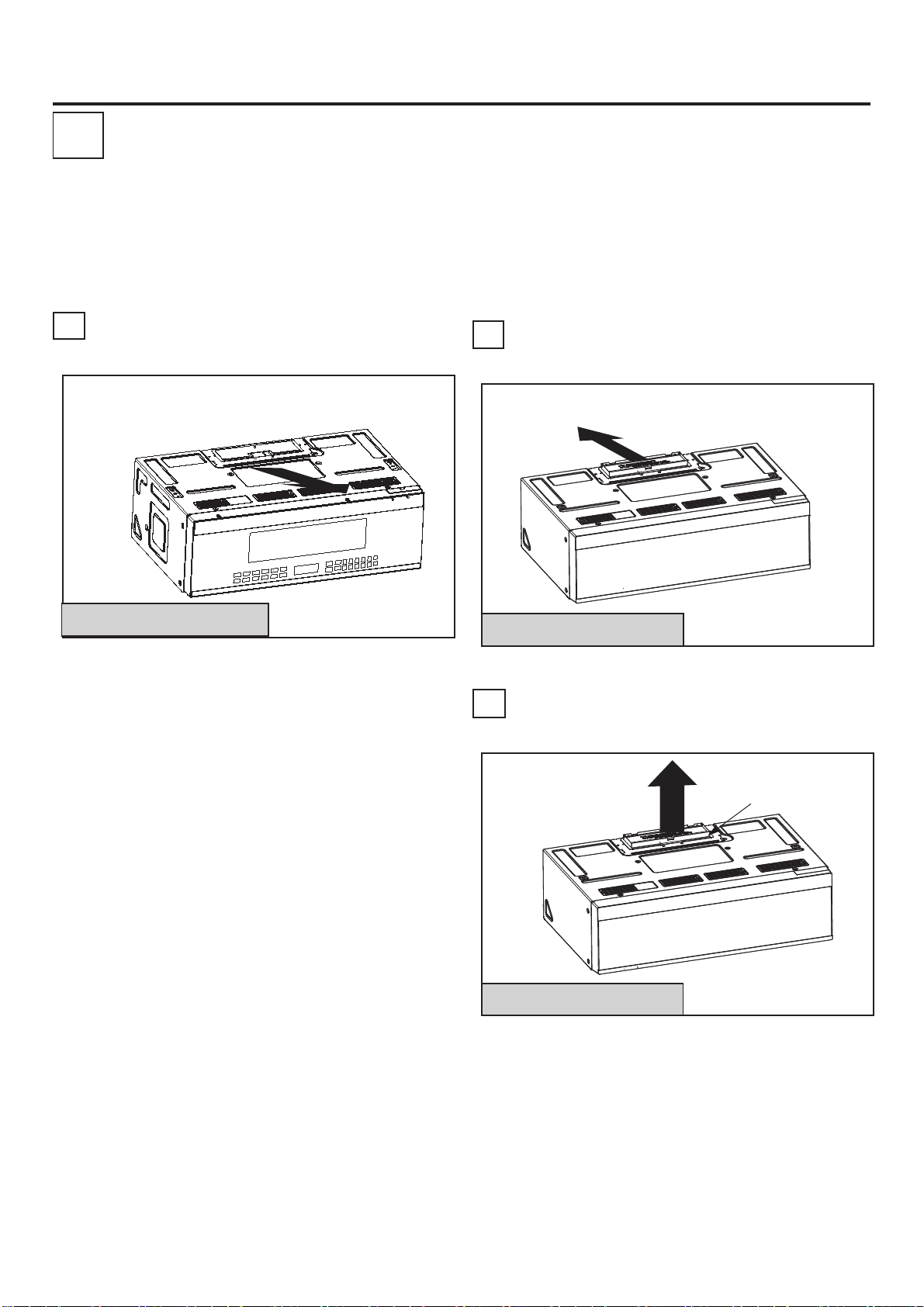
Instructions d’installation
2
TYPES D’INSTALLATION
Ce four à micro-ondes est conçu pour s’adapter aux
trois types d’évacuation suivants :
A. Évacuation à l’extérieur par le dessus (conduit
vertical)
B. Évacuation à l’extérieur par l’arrière (conduit
horizontal)
C. Recyclage (sans conduit)
RECYCLAGE D’AIR (ÉVACUATION
A
.
SANS CONDUIT)
(Choisissez A, B ou C)
REMARQUE: Ce four à micro-ondes est équipé à
l’usine en vue d’une Recyclage .
Choisissez le type d’évacuation approprié à votre
installation et rendez-vous à cette section.
ÉVACUATION À L’EXTÉRIEUR PAR
B.
L’ARRIÈRE (CONDUIT
HORIZONTAL)
L’adaptateur doit être placé à
l’arrière pour une évacuation à
l’extérieur par l’arrière
Consultez la page 10
Sur les modèles conçus pour le recyclage d’air,
un filtre à charbon jetable est installé en usine
pour retenir la fumée et les odeurs.
Consultez la page 15
C.
ÉVACUATION À L’EXTÉRIEUR PAR
LE DESSUS (CONDUIT VERTICAL)
Adaptateur en place pour
une évacuation à l’extérieur
par le dessus
Consultez la page 19
REMARQUE: Ne lisez les pages 13 - 14 suivantes que si vous décidez d’évacuer l’air du ventilateur à l’extérieur.
Si vous décidez de recycler l’air dans la pièce, rendez-vous à la page 10.
FR-9
Page 59

Instructions d’installation
RECYCLAGE D’AIR
A
(évacuation sans conduit)
VUE D’ENSEMBLE DE L’INSTALLATION
C1. Fixation de la plaque de montage au mur
C2. Préparation de l’armoire supérieure
C3. Vérification de l’plaque du ventilateur
C4. Installation du four à micro-ondes
C5. Installation ou changemeut du filtre à charbon
REMARQUES IMPORTANTES :
• Assurez-vous que les vis du moteur du ventilateur et
de la plaque du ventilateur sont solidement vissées
lorsque vous les remettez en place. Cela évitera les
vibrations excessives.
• Assurez-vous que les fils du moteur sont bien
acheminés, fixés et qu’ils ne sont pas coincés.
FIXATION DE LA PLAQUE DE
A1.
MONTAGE AU MUR
TO
T
N
TA
R
PO
M
I
RY
E
V
T IS
I
:
TE
O
N
NS
IO
T
C
E
R
I
D
THE
W
OLLO
F
D
N
A
D
REA
ON
CTI
U
TR
NS
ION I
T
ALLA
T
NS
I
THE
N
I
IS
H
T
WITH
G
N
DI
E
CE
O
R
P
E
R
O
F
E
B
ATE.
L
P
TEM
LL
A
AR W
RE
tto
o
b
e
th
n
ositio
to p
ves
r
e
s
e
at
l
p
m
Te
ll
Wa
r
a
e
R
s
Thi
t
s
hau
ex
l
a
t
n
o
iz
or
h
e
h
t
e
t
a
c
o
l
to
d
an
ate
g pl
in
nt
u
o
m
.
t
e
utl
o
e
ition
s
o
p
is
te
la
mp
e
t
e
h
t
at
h
t
eck
h
c
to
l
ve
e
l
a
se
U
.
1
y.
el
t
accura
r
o
ft
e
l
on the
d
stu
e
n
st o
a
e
l
at
k
r
a
ndm
a
cate
o
L
2.
.
ine
l
r
te
n
e
e c
h
t
of
ide
s
ht
ig
r
d
o
wo
t one
as
e
l
at
use
o
t t
an
rt
po
s im
It i
ht
he weig
t t
or
p
sup
to
d
stu
a
n
i
y
l
m
r
nted fi
mou
w
re
c
s
ed
c
a
p
venlys
e
l,
ona
ti
addi
o
tw
ark
M
.
ve
a
w
icro
m
the
of
s.
lt
o
b
e
l
g
g
to
ed
ppli
u
s
e
h
for t
s
ion
cat
lo
s
i
e
r
he
t
e
r
e
Wh
s.
on
ti
ca
o
l
rked
a
m
the
n
i
s
le
o
h
ll
ri
D
3.
ole
h
r
. Fo
ws
e
cr
s
d
woo
or
f
le
o
h
16"
3/
a
l
il
r
d
,
d
a stu
or
f
s
hole
"
/8
l 5
l
i
r
d
tud,
a s
ith
e upw
in
t l
do no
that
ts.
l
bo
le
gg
to
TE
A
L
P
G
IN
T
N
U
MO
E
L TH
AL
T
S
N
I
T
NO
O
D
.
E
IM
T
HIS
T
T
A
.
all
w
e rear
mth
o
fr
te
la
mp
move the te
e
R
4.
r
u
o
y
or
k f
oo
b
n
o
i
t
uc
r
t
ns
I
on
i
t
a
ll
a
t
s
n
I
e
t
w
ieh
v
e
R
.
5
on.
i
t
itua
n s
atio
nstall
i
la
r
a
ult
s
n
o
parac
a
j
o
h
a
l
taa
l
e
u
v
e
arl
D
.
l
o
añ
p
nEs
e
n
ó
i
rs
e
v
es to align
ol
h
rk
a
m
nd
a
te
a
Loc
gplate.
tin
un
o
m
:
NT
A
RT
PO
M
I
UD
T
S
E
N
T O
S
LEA
T
A
E
T
CA
O
L
.
RLINE
E
NT
E
C
E
H
T
2
R
O
F
N
O
CATI
O
L
HE
KT
MAR
N THE
I
S
T
E BOL
GGL
O
T
D
ACE
P
S
.
EA
R
A
ed
t
t
do
e
h
t
along
ate
pl
all tem
w
r
ea
r
he
t
m
i
Tr
Enlevez les écrous à ailettes des boulons.
1
Insérez les boulons dans la plaque de montage
2
E
G
ED
TO
"
8
3/
S
m
12"
d
4"
s
e
h
t
in
s
le
ho
th
wi
F
O
E
ID
S
ER
TH
N EI
O
LY
EVEN
L,
IONA
T
I
ADD
E
AT
G PL
IN
NT
U
O
M
.
ne
li
.
e
lin
d
te
ot
d
he
t
g
lon
a
e
at
pl
m
e
t
l
l
r wa
ea
r
he
t
rim
T
n the
i
es
ol
h
th
gn wi
es to ali
ol
h
k
mar
e and
t
Loca
.
e
ta
l
p
g
n
it
n
u
o
m
:
NT
A
RT
IMPO
F
E O
R SID
HE
N EIT
O
D
U
ST
E
ON
T
EAS
T L
A
E
T
LOCA
E.
IN
L
ER
T
EN
C
THE
LY
EN
V
E
L,
A
N
O
I
T
2 ADDI
R
O
F
ION
T
A
C
LO
HE
T
RK
A
M
LATE
P
UNTING
N THE MO
LTS I
E BO
GL
G
O
T
D
E
AC
P
S
EA.
AR
à travers les trous dans le gypse et réassemblez
les écrous à ailettes, à 3/4 po (19 mm) sur
chaque boulon.
Fixez la plaque au mur à l’aide des boulons à
ailettes. Vous devez utiliser au moins une vis à bois
pour fixer la plaque à un montant.
REMARQUE: Si la profondeur du armoire incluant
les portes du armoire est plus de 13''
alors l'unité doit être espacée du mur
utilisant des matériaux adéquats
supportant 150 lbs pour permettre une
bonne ventilation d'air au
sommet/admission d'air.
13,8" MAX.
(35 cm)
Armoire
Armoire
Pour utiliser les boulons à ailettes :
Espace pour les ailettes
supérieur à l’épaisseur du
mur
Plaque de
montage
Placez la plaque de montage contre le mur et
3
insérez les écrous à ailettes dans les trous du
mur pour fixer la plaque.
REMARQUE: Avant de resserrer les boulons à
ailettes et la vis à bois, assurez-vous que la plaque
est bien centrée sous l’armoire et que les
languettes de la plaque de montage touchent le
dessous de l’armoire lorsque vous poussez la
plaque contre le mur.
ATTENTION: Faites attention de ne pas vous pincer
les doigts entre l’arrière de la plaque de montage
et le mur.
Serrez tous les boulons. Tirez sur la plaque
4
pour faciliter le serrage des boulons.
Écrou à ailettes
Boulon à
ailettes
Mur
Extrémité du boulon
FR-10
Page 60
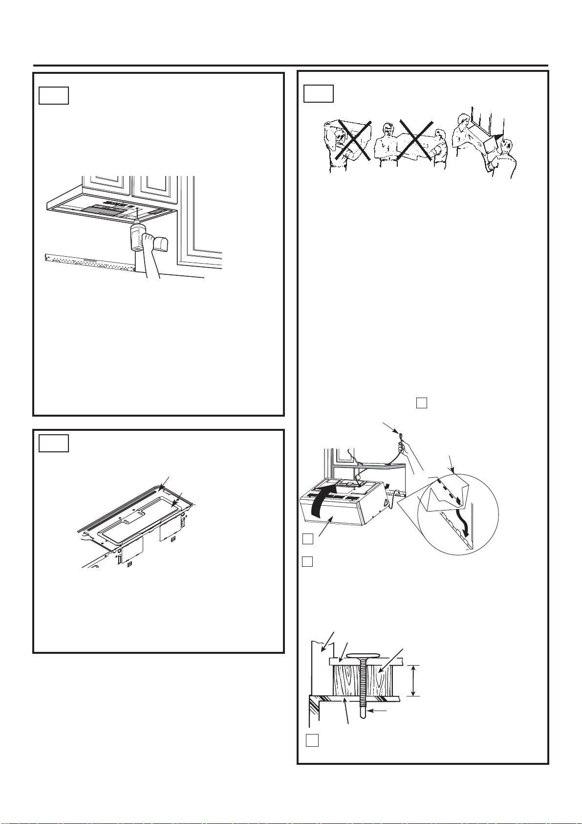
Instructions d’installation
UTILISATION DU GABARIT
A2.
POUR ARMOIRE SUPÉRIEURE
POUR LA PRÉPARATION DE
L’ARMOIRE SUPÉRIEURE
Vous devez percer des trous pour les vis de soutien
supérieures, ainsi qu’un trou suffisamment grand
pour y faire passer le cordon d’alimentation.
• Lisez les instructions sur le GABARIT POUR
ARMOIRE SUPÉRIEURE.
• Collez-le sous l’armoire supérieure à l’aide de
ruban adhésif.
REMARQUE: Ajustez correctement le haut du
gabarit si le micro-ondes devient espacé du mur à
cause de la profondeur du armoire (incluant les
portes du armoire) de plus de 13".
• Percez les trous, en suivant les instructions du
GABARIT POUR ARMOIRE SUPÉRIEURE.
ATTENTION : Portez des lunettes de sécurité lorsque
vous percez des trous dans le fond de l’armoire.
A3.
VÉRIFICATION DE L’PLAQUE
DU VENTILATEUR
Plaque de Ventilation
Plaque du Couvercle
INSTALLATION DU FOUR À
A4.
MICRO-ONDES
POUR VOTRE SÉCURITÉ ET POUR FACILITER
L’INSTALLATION, L’INSTALLATION DE CE FOUR
DOIT ÊTRE EFFECTUÉE PAR DEUX PERSONNES.
IMPORTANT: Ne pas saisir ou utiliser la poignée ou
l'écran thermique durant l'installation. Ne pas
retirer les entretoises en carton entre l'écran
thermique et la porte.
REMARQUE: Si vos armoires sont en métal,
installez un passe-fil en nylon autour de l’orifice du
cordon d’alimentation pour empêcher que le
cordon soit coupé.
REMARQUE: Si le four est installé sous une armoire
dotée d’un rebord avant, nous vous
recommandons d’utiliser des entretoises.
IMPORTANT: Si vous n’utilisez pas d’entretoises,
des dommages peuvent être causés au boîtier au
moment de resserrer les vis.
REMARQUE: Lors de l’installation
du four à micro- ondes, faites
passer le cordon d’alimentation à
travers le trou situé dans le fond de
l’armoire supérieure. Gardez-le bien
serré durant les étapes 1 à 3. Ne
coincez pas le cordon ou
ne soulevez pas le four en tirant sur
le cordon.
Soulevez le four à micro-
1
ondes, penchez-le vers l’avant
et accrochez les fentes du bord
inférieur de l’arrière du four sur
les quatre languettes
inférieures de la plaque de
montage.
• Placez le four à micro-ondes en position
debout, le dessus de l’appareil sur le dessus.
• Inspectiez pour affirmer le ventilateur metal
est installez dans la cavité.
FR-11
Relevez le devant du four pour
2
le mettre contre le dessous de
l’armoire.
Insérez une vis à auto-alignement dans le trou situé au centre
3
de l’armoire supérieure. Fixez temporairement le four en faisant
faire au moins deux tours complets à la vis après que les filets
aient été engagés. (Elle sera
complètement resserrée plus tard.) Assurez-vous que le cordon
d’alimentation est bien serré. Faites attention de ne pas le
coincer, particulièrement au moment d’installer le four sous
l’armoire.
Avant de l’armoire
Étagère inférieure de l’armoire
Entretoise
Équivalent à la
profondeur du rebord
de l’armoire
Vis à auto-alignement
Dessus du four à micro-ondes
Fixez le four à micro-ondes à l’armoire
4
supérieure.
Page 61
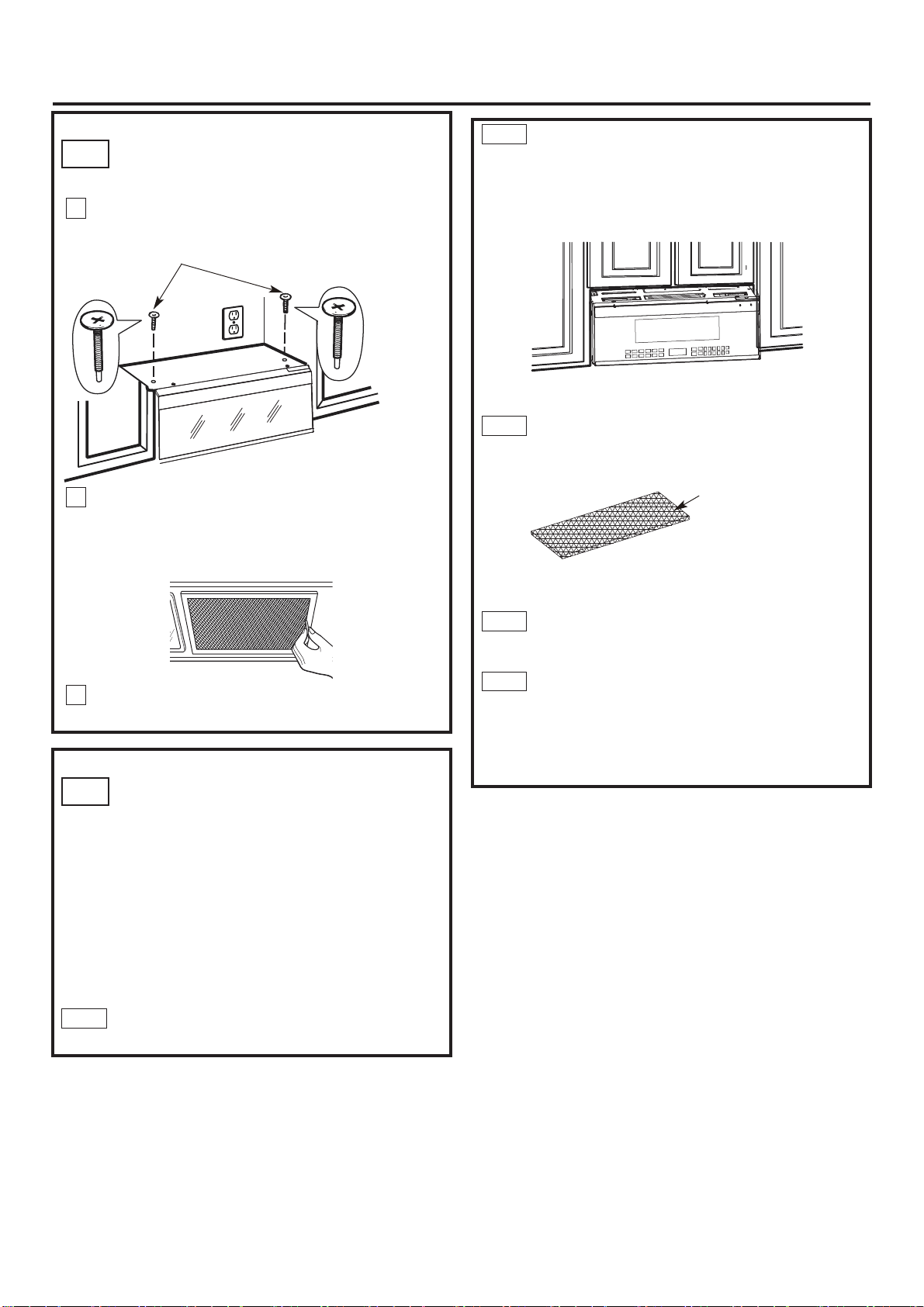
Instructions d’installation
A4.
INSTALLATION DU FOUR À
MICRO-ONDES
5
Insérez deux vis à auto-alignement à travers les
trous de l’armoire supérieure. Faites faire deux
tours complets à chaque vis.
6
Serrez les deux vis de chaque côté dans le
dessus du four à micro-ondes. (Tout en serrant
les vis, soulevez l’avant du four à micro-ondes et
poussez-le contre le mur et l’armoire
supérieure.)
(suite)
A 5.2
A 5.3
Retirer le support d'air en plastique situé
sur le dessus du micro-ondes.
Changer le filtre à charbon.
Filtre à
Charbon
7
Installez les filtres. Consultez le Manuel de
l’utilisateur emballé avec le four.
INSTALLATION OU
A5.
CHANGEMEUT DU FILTRE
À CHARBON
REMARQUE: Le filtre à charbon de bois est
installé d'usine dans certains modèles.
Reférez-vous à l'utilisation et soin pour voir si le
vôtre est installé d'usine et pour l'information de
remplacement.
Pour le modèle sans la porte d'accès au filtre de
recirculation, suivez ces étapes pour remplacer
ou installer un filtre à charbon de bois.
Débranchez le four à micro-ondes ou
A 5.1
déconnectez l'alimentation.
(Certains modèles)
A 5.4
A 5.5
Installer le support d'air en plastique situé
sur le dessus du micro-ondes.
Fermer la porte du four à micro-ondes.
Brancher le four à micro-ondes ou le
rebrancher.
FR-12
Page 62
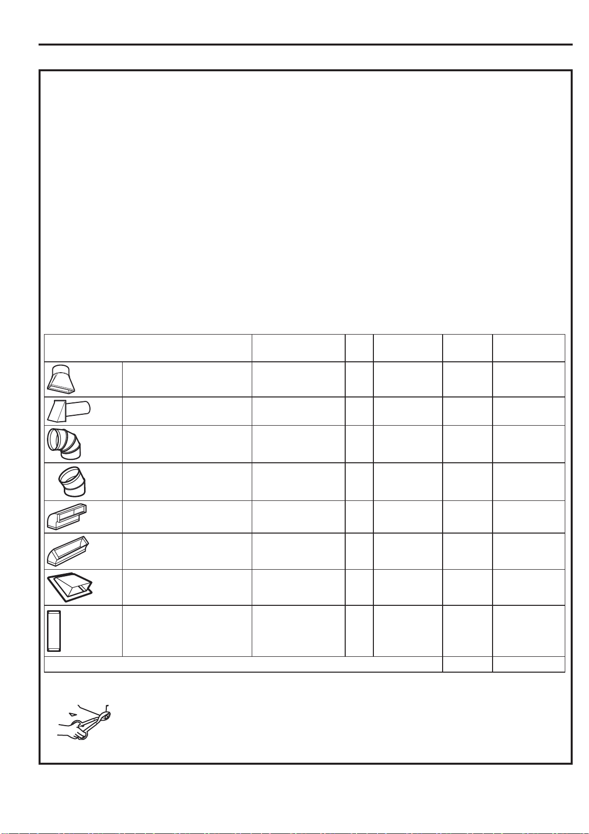
Instructions d’installation
INSTRUCTIONS POUR L`INSTALLATION EXTERIEURE DE CODUITS D`ECHAPPEMENT.
REMARQUE : Si vous devez installer des conduits, notez
que la longueur totale du conduit rectangulaire de 3
po x 10 po (8,2 x 25,4 cm) ou du conduit rond de 5 po
(12,7cm)/6 po (15,2 cm) de diamètre ne doit pas être
supérieure à 140 pi (42,7m) de longueur équivalente.
L’évacuation vers l’extérieur requiert un CONDUIT
D’ÉVACUATION POUR HOTTE. Lisez attentivement ce qui
suit.
REMARQUE: Il est important que l’évacuation soit
installée en utilisant le chemin le plus direct et avec le
moins de coudes possible. Cela assure une bonne
évacuation et aide a prévenir
les blocages. Assurez-vous également que les registres
bougent librement et que rien ne bloque les conduits.
1/4"
Connexion d'échappement:
L'adaptateur d'échappement a été conçu pour s'accoupler
avec une
canalisation rectangulaire standard de 3
25,4 cm). Si une canalisation ronde est recquise, un
adaptateur de transition rectangulaire-rond doit être
utilisé. Une canalisation de diamètre 5 po (12,7cm) / 6 po
(15,2cm) est acceptable à utiliser.
PIÈCES DE CONDUIT x =
1/4" x 10 po (8.2 x
LONGUEUR
ÉQUIVALENTE
Longueur maximale du conduit:
Pour une circulation d’air satisfaisante, la longueur totale
du conduit rectangulaire de 3
ou du conduit rond de 5 po (12,7cm) / 6 po (15,2 cm) de
diamètre ne doit pas excéder une longueur équivalente à
140 pi (42,7m)
Les coudes, adaptateurs de transition, évents
muraux ou de toiture, etc.
supplémentaire à la circulation de l’air et sont
équivalents à une section de conduit droit plus longue que
leur dimension réelle. Lorsque vous calculez la longueur
totale du conduit, ajoutez les longueurs équivalentes de
tous les adaptateurs de transition et des coudes, ainsi que
la longueur de toutes les sections de conduit droit. Vous
trouverez dans le tableau ci-dessous la longueur
équivalente approximative en pieds et en mètres de
certains types de conduits.
NOMBRE
UTILISÉ
1/4" x 10 po (8,2 x 25,4 cm)
offrent une résistance
LONGUEUR
ÉQUIVALENTE
Longueur totale
Adaptateur de transition*
Évent mural
Coude de 90°
Coude de 45°
Coude de 90°
Coude de 45°
Évent de toiture
Conduit droit rond de 6 po
(15,2 cm) ou rectangulaire
de
3 1/4" x 10 po (8,2 x 25,4
cm)
5 pi (1,5 m) ( )
40 pi (12,2 m)
10 pi (3 m)
5 pi (1,5 m)
25 pi (7,6 m)
5 pi (1,5 m)
24 pi (7,3 m)
1pi (0,3m)
x
x
( )
x
( )
x
( )
x
( )
x
( )
x
( )
x
( )
=
=
=
=
=
=
=
=
pi ou m
pi ou m
pi ou m
pi ou m
pi ou m
pi ou m
pi ou m
pi ou m
pi ou m
* IMPORTANT: Si vous utilisez un
adaptateur de transition, il faudra
couper les coins inférieurs du registre
aux dimensions de l’adaptateur à l’aide
de cisailles pour que le registre puisse
bouger.
FR-13
Les longueurs équivalentes des pièces de
conduits sont basées sur des essais réels et
représentent les longueurs nécessaires à une
bonne ventilation pour n’importe quelle hotte.
Page 63
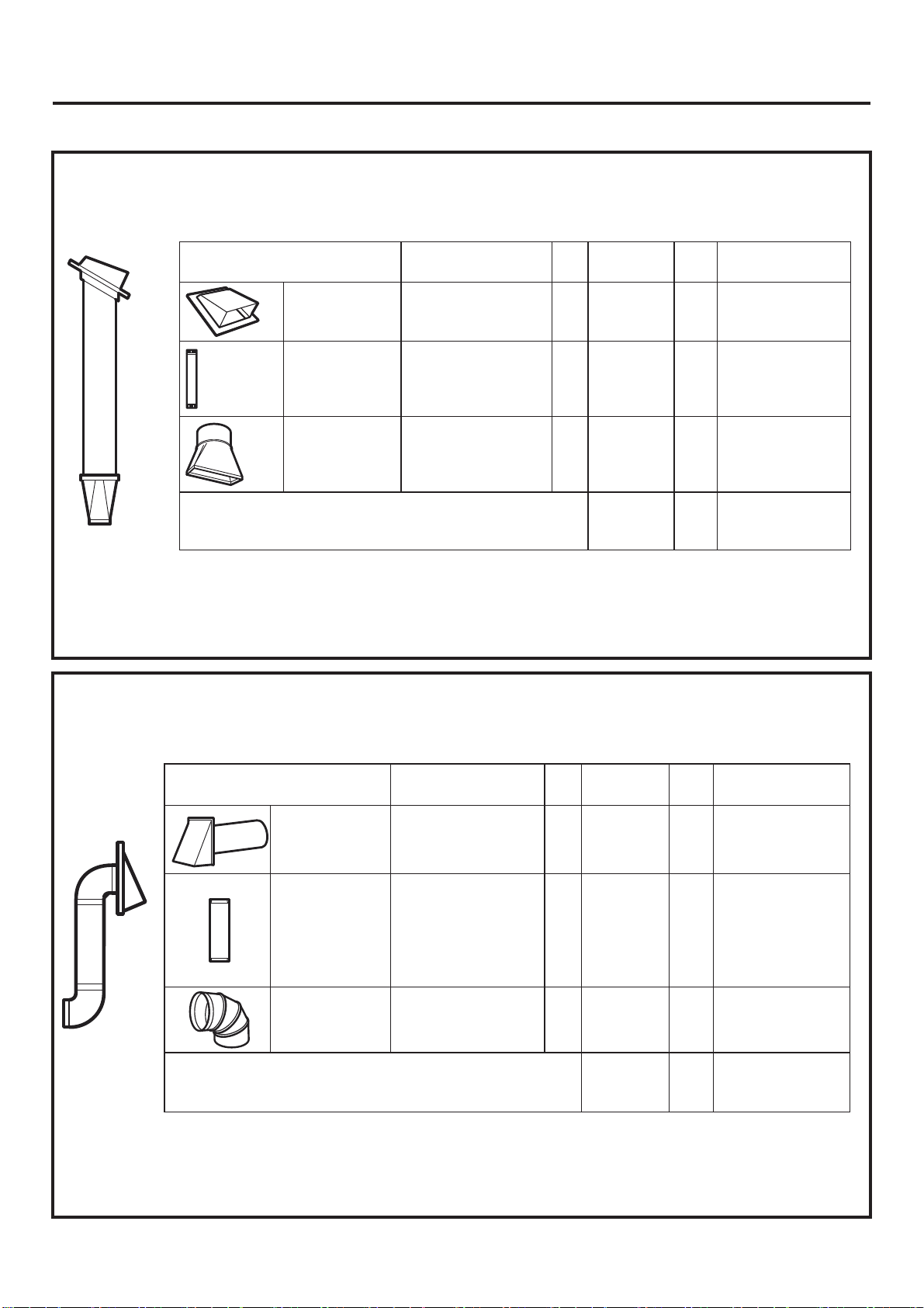
Instructions d’installation
CANALISATION D'ECHAPPEMENT EXTERNE
ÉVACUATION À L’EXTÉRIEUR PAR LE DESSUS (EXEMPLE SEULEMENT)
Le tableau suivant décrit un exemple d’installation de conduit.
PIÈCES DE
CONDUIT
Évent de
toiture
Conduit droit
de 12 pi (3,6 m)
(rond de 6
po/15,2 cm)
Adaptateur de
transition*
Les longueurs équivalentes des pièces de conduits sont basées
sur des essais réels et représentent les longueurs nécessaires à
une bonne ventilation pour n’importe quelle hotte.
LONGUEUR
ÉQUIVALENTE
24 pi (7,3 m)
12 pi (3,6 m)
5 pi (1,5 m)
x =
x
x
x
NOMBRE
UTILISÉ
( 1 )
( 1 )
( 1 )
Longueur
totale
LONGUEUR
ÉQUIVALENTE
=
=
=
24 pi (7,3 m)
12 pi (3,6 m)
5 pi (1,5 m)
41 pi (12,5 m)
* IMPORTANT: Si vous utilisez un adaptateur de transition, il faudra couper les coins
inférieurs du registre aux dimensions de l’adaptateur à l’aide de cisailles pour que le registre
puisse bouger.
ÉVACUATION À L’EXTÉRIEUR PAR L’ARRIÈRE (EXEMPLE SEULEMENT)
Le tableau suivant décrit un exemple d’installation de conduit.
PIÈCES DE
CONDUIT
Évent mural
Conduit droit
de 3 pi (0,91m)
(rectangulaire
3
1/4" x 10 po/
8,2 x 25,4 cm)
Coude de 90°
Les longueurs équivalentes des pièces de conduits sont basées
sur des essais réels et représentent les longueurs nécessaires à
une bonne ventilation pour n’importe quelle hotte.
LONGUEUR
ÉQUIVALENTE
40 pi (12,2 m)
3 pi (0.9 m)
10 pi (3 m)
NOMBRE
x =
UTILISÉ
x
( 1 )
x
( 1 )
x
( 1 )
Longueur
totale
LONGUEUR
ÉQUIVALENTE
=
40 pi (12,2 m)
=
3 pi (0.9 m)
=
20 pi (3 m)
63 pi (19,2 m)
REMARQUE :Dans le cas d’une évacuation par l’arrière, veillez à aligner le conduit
d’évacuation sur les espaces entre les montants, ou à préparer le mur au moment de la
construction en laissant assez d’espace entre les montants pour recevoir le conduit.
FR-14
Page 64
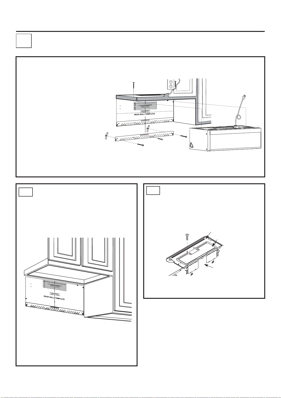
Instructions d’installation
ÉVACUATION À L’EXTÉRIEUR PAR L’ARRIÈRE
B
(Conduit horizontal)
VUE D’ENSEMBLE DE L’INSTALLATION
B1. Préparation du mur arrière
B2. Enlèvement de l’plaque du ventilateur
B3. Fixation de la plaque de montage au mur
B4. Préparation de l’armoire supérieure
B5. Ajustement du ventilateur
B6. Installation du four à micro-ondes
REMARQUES IMPORTANTES :
• Assurez-vous que les vis du moteur du
ventilateur et de la plaque du
ventilateur sont solidement vissées
lorsque vous les remettez en place.
Cela évitera les vibrations excessives.
• Assurez-vous que les fils du moteur
sont bien acheminés, fixés et qu’ils ne
sont pas coincés.
O
T
NT
TA
OR
P
M
RY I
E
V
IT IS
:
TE
O
N
NS
IO
CT
RE
I
D
HE
T
W
O
LL
ND FO
A
D
REA
S
ION
CT
U
R
T
NS
I
N
O
I
T
LLA
A
NST
I
THE
N
I
IS
H
WITH T
DING
CEE
O
R
P
RE
O
F
E
B
.
TE
A
MPL
TE
L
L
A
R W
A
RE
m
otto
b
e
th
n
o
ti
i
s
o
p
o
t
s
e
serv
e
t
a
l
mp
e
T
ll
Wa
r
a
e
R
s
hi
T
t
s
hau
tal ex
n
o
horiz
e
h
t
te
ca
o
eand to l
t
a
l
p
g
n
ti
n
ou
m
t.
e
outl
ed
on
iti
os
is p
ate
l
p
em
t
e
at th
h
k t
ec
ch
to
l
ve
le
a
e
Us
.
1
y.
el
at
r
accu
t or
ef
l
n the
o
d
estu
on
t
t leas
k a
ar
m
nd
e a
t
oca
2. L
.
e
in
rl
e
nt
e
the c
f
o
de
ight si
r
wood
ne
t o
as
le
t
a
use
o
t t
an
ort
p
im
is
It
t
h
g
e wei
h
t t
or
tud to supp
s
n a
y i
l
rm
fi
d
nte
u
o
w m
e
cr
s
aced
ysp
al, evenl
ion
addit
wo
k t
ar
M
.
ave
w
o
micr
e
ofth
ts.
l
bo
gle
g
o
t
ed
i
l
upp
s
e
th
or
f
s
ation
c
o
l
s
i
there
e
r
he
s.W
n
o
i
t
loca
d
e
ark
m
e
th
n
i
s
ole
h
ll
i
r
D
3.
s
le
o
h
For
.
ws
e
r
d sc
woo
or
f
le
o
h
"
6
1
/
3
a
ill
dr
d,
u
a st
r
s fo
le
ho
"
8
/
5
l
il
r
d, d
tu
s
a
ith
w
p
u
ine
l
not
o
td
ha
t
.
ts
l
bo
le
gg
o
t
E
LAT
G P
IN
T
UN
HE MO
L T
NSTAL
T I
DO NO
.
E
IM
T
S
HI
T
AT
wall.
r
a
e
r
e
h
tm
o
te fr
la
p
tem
the
ove
m
e
R
.
4
r
ou
y
or
k f
o
tion bo
c
u
r
nst
I
tion
a
ll
a
st
n
I
e
h
t
w
e
i
v
e
R
5.
.
on
i
t
ua
t
i
n s
o
i
at
ll
sta
in
a
l
ar
t
l
u
s
con
ra
ap
a
jo
ha
l
a
a
t
l
vue
e
l
Dar
ol.
ñ
a
Esp
n
e
n
ó
si
r
e
v
e
n th
i
s
le
o
h
ith
w
align
rk holes to
a
d m
n
cate a
Lo
te.
a
pl
g
tin
n
u
o
m
:
ANT
RT
O
P
IM
F
O
E
ID
S
ER
N EITH
O
STUD
E
ON
ST
EA
L
T
E A
T
A
LOC
.
E
LIN
R
E
ENT
C
E
TH
Y
AL, EVENL
N
2 ADDITIO
R
FO
TION
A
C
HE LO
T
K
AR
M
E
T
PLA
MOUNTING
N THE
I
TS
L
BO
LE
OGG
T
D
PACE
S
.
EA
R
A
.
e
n
d li
e
tt
o
d
e
th
g
on
l
a
te
a
pl
m
e
ll t
a
w
r
a
e
r
he
t
Trim
E
EDG
TO
"
8
3/
12"
4"
L
IM
L
T
M
SP
AR
.
e
n
li
d
e
t
ot
d
he
t
long
a
e
mplat
e
l t
wal
ar
e
he r
t
Trim
the
n
es i
l
ho
h
it
w
gn
li
a
to
les
o
h
k
r
a
m
nd
a
ate
c
o
.
e
t
a
l
i
p
nu
g
n
t
om
:
T
N
A
T
OR
P
OF
E
D
I
S
R
N EITHE
O
D
U
EST
ON
T
S
A
E
L
AT
E
T
OCA
E.
N
I
L
R
E
NT
E
C
HE
Y
NL
E
, EV
L
A
N
O
ITI
DD
A
2
FOR
N
IO
CAT
O
L
HE
T
RK
A
E
T
LA
P
G
OUNTIN
M
E
H
T
IN
S
OLT
B
GGLE
TO
D
CE
A
EA.
PRÉPARATION DU MUR
B1.
ARRIÈRE POUR
L’ÉVACUATION À
L’EXTÉRIEUR PAR L’ARRIÈRE
Vous devez percer une ouverture dans le mur
arrière
pour l’évacuation à l’extérieur.
NO
TE
: IT IS VE
R
E
RY IM
AD
A
POR
ND
FOLL
T
IN T
ANT
OW
HE INSTA
TO
TH
E
DIR
BEFO
L
LATIO
ECTIONS
RE
N
PROCEEDING
INSTR
RE
AR
U
CTIO
WALL
NS
WITH
TEMPLATE
Th
THI
is
Rear
S
W
.
all
m
Te
ount
m
pl
in
at
g
e s
pl
er
a
te
v
es
ou
a
nd
t
t
let
o
t
p
o
.
osit
lo
c
i
a
on
t
e
t
t
h
he
1.
e bot
Us
hori
e
t
om
z
a
o
ntal
le
vel
exhaust
t
o check
accurat
that
ely.
t
h
e
2.
t
e
Locat
m
pla
t
e
e
and
is
positione
mark
right
a
t
d
side
lea
s
t
on
o
f
t
e
h
e
st
ce
ud
nt
on the
erl
ine.
It
is
l
ef
im
t
or
portant t
scr
ew
mou
o
u
se at
n
t
e
d
of
leas
f
irmly
th
e
t
in
microw
on
a
e wood
st
ud
ave.
loca
t
o
Mar
s
ti
up
on
port
k
s
t
wo a
f
or
t
he
t
h
ddition
e
wei
3.
s
Dr
uppl
ght
ill
al,
ied
h
oles
ev
t
ogg
enly
in
le
t
spa
h
bolt
e
a st
m
ced
s.
arked loca
ud,
dri
ll
a
3
t
io
/
t
1
hat
ns.
6"
ho
Wh
do
le
n
ere
f
ot li
or wood
t
ne
h
er
t
up
oggle
e
i
s
screws. F
with
b
olts
a stud,
.
o
r
drill
holes
5
/
8
"
D
hole
O
NOT
s
f
or
AT
IN
T
S
HI
T
S
ALL
T
I
M
T
E.
HE
4.
Rem
MO
UN
o
ve
T
I
NG
the
P
5.
t
emplat
LAT
R
eview
E
e
from
th
e I
the
nstal
in
rear
stallat
la
t
io
wall.
n
io
In
n
s
tr
situat
uc
t
ion
io
n.
bo
o
k
f
or
y
our
Darle
vu
elta
a
ver
la
ho
sión
ja
pa
en
r
a
Espa
co
n
ñ
sul
ol.
tar
la
Lo
cate
and
mark hol
mou
es to
nti
ng p
alig
late
n with holes
.
IMP
O
RTA
in the
NT:
LOCATE
AT LE
AST ON
TH
E
C
ENTER
E
STU
D
LIN
O
M
E
N
A
.
EITH
R
K TH
ER
E L
S
OC
ID
E
SP
AT
O
ACE
ION FOR
F
D TOGG
2 AD
AREA.
LE BO
D
IT
I
O
LTS IN
NAL,
EVENLY
TH
E
MOUNTIN
G
PLA
TE
Trim the
r
ea
r wa
ll templa
te a
l
o
n
g the d
otted
line.
3
/8" TO E
D
GE
12"
4"
Tri
m
the
rea
r
wal
l
te
mpla
te
a
l
o
ng
the
d
otted
lin
e
.
Lo
cate
and
mar
k holes to
mo
unti
ng
a
p
lign w
late
.
ith h
IMPORTA
o
les in the
NT:
LO
CAT
E
AT LE
AST ON
TH
E CE
E
N
STU
TER
D O
LIN
MA
E.
N EIT
RK TH
H
ER SIDE
E
L
OCAT
SP
O
ACE
IO
F
N FOR
D TOGG
2 AD
LE
AR
DIT
BOLTS
EA.
IO
NAL
IN
, EVEN
THE
M
LY
OU
NTIN
G PLATE
B2.
RETIRER LA PLAQUE DE
VENTILATION
Retirer et conserver la vis qui maintient la
plaque de ventilation sur le four à
micro-ondes. Soulever la plaque de
ventilation.
Plaque de Ventilation
Plaque du Couvercle
Arrière du Four à
micro-ondes
• La plaque du couvercle est installée avec la
plaque de ventilation, il n'est pas nécessaire
de séparer.
• Lisez les instructions figurant sur le GABARIT
POUR MUR ARRIÈRE.
• Collez-le au mur arrière.
• Percez l’ouverture en suivant les instructions sur le
GABARIT POUR MUR ARRIÈRE.
FR-15
Page 65
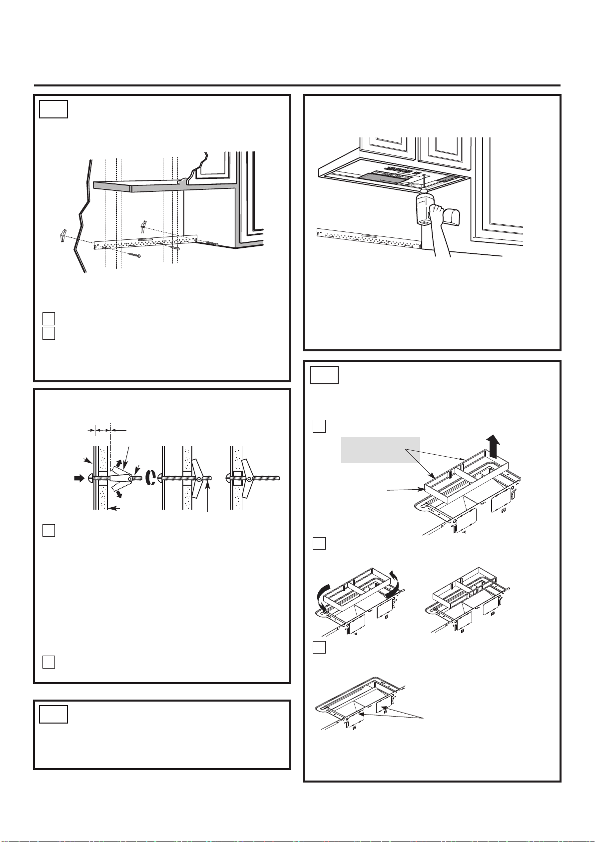
Instructions d’installation
B3.
FIXATION DE LA PLAQUE DE
MONTAGE AU MUR
Fixez la plaque au mur à l’aide des boulons à
ailettes. Vous devez utiliser au moins une vis à
bois pour fixer la plaque à un montant.
Enlevez les écrous à ailettes des boulons.
1
Insérez les boulons dans la plaque de montage
2
à travers les trous dans le gypse et réassemblez
les écrous à ailettes, à 3/4 po (19 mm) sur
chaque boulon.
Pour utiliser les boulons à ailettes :
Espace pour les ailettes supérieur à
l’épaisseur du mur
Plaque de
montage
Écrou à ailettes
Boulon à
ailettes
Vous devez percer des trous pour les vis de soutien
supérieures, ainsi qu’un trou suffisamment grand
pour y faire passer le cordon d’alimentation.
• Lisez les instructions sur le GABARIT POUR
ARMOIRE SUPÉRIEURE.
• Collez-le sous l’armoire supérieure à l’aide de
ruban adhésif.
• Percez les trous, en suivant les directives du
GABARIT POUR ARMOIRE SUPÉRIEURE.
ATTENTION: Portez des lunettes de sécurité lorsque
vous percez des trous dans le fond de l’armoire.
B5.
ADAPTATION D'UN SYSTEME
DIRECTEUR D'AIR DU FOUR A
MICRO-ONDES POUR LA
SORTIE ARRIERE EXTERNE
Retirer délicatement le système directeur d'air.
1
Avant : Ouvertures
Vers l'Avant
Mur
Placez la plaque de montage contre le mur et
3
insérez les écrous à ailettes dans les trous du
mur pour fixer la plaque.
REMARQUE: Avant de resserrer les boulons à ailettes
et la vis à bois, assurez-vous que la plaque est bien
centrée sous l’armoire et que les languettes de la
plaque de montage touchent le dessous de l’armoire
lorsque vous poussez la plaque contre le mur.
ATTENTION: Faites attention de ne pas vous pincer
les doigts entre l’arrière de la plaque de montage et
le mur.
Serrez tous les boulons. Tirez sur la plaque pour
4
faciliter le serrage des boulons.
B4.
UTILISATION DU GABARIT
Extrémité du boulon
POUR ARMOIRE SUPÉRIEURE
POUR LA PRÉPARATION DE
L’ARMOIRE SUPÉRIEURE
Système
Directeur d’Air
Faire pivoter le système directeur d'air de 180°
2
dans le sens inverse aux aiguilles d'une montre.
Avant Rotation Après Rotation
Retirer les plaques amovibles à l'arrière de
3
l'appareil à l'aide de ciseaux. (Pour certains
modèles)
Arrière du four
micro-ondes
Plaques amovibles :
Couper les 4 bandes de
chaque plaque amovible
et retirer les supports
métalliques au niveau de
la ventilation arrière.
Veiller à éliminer toute
bord tranchant créé par le
retrait des plaques
amovibles.
FR-16
Page 66
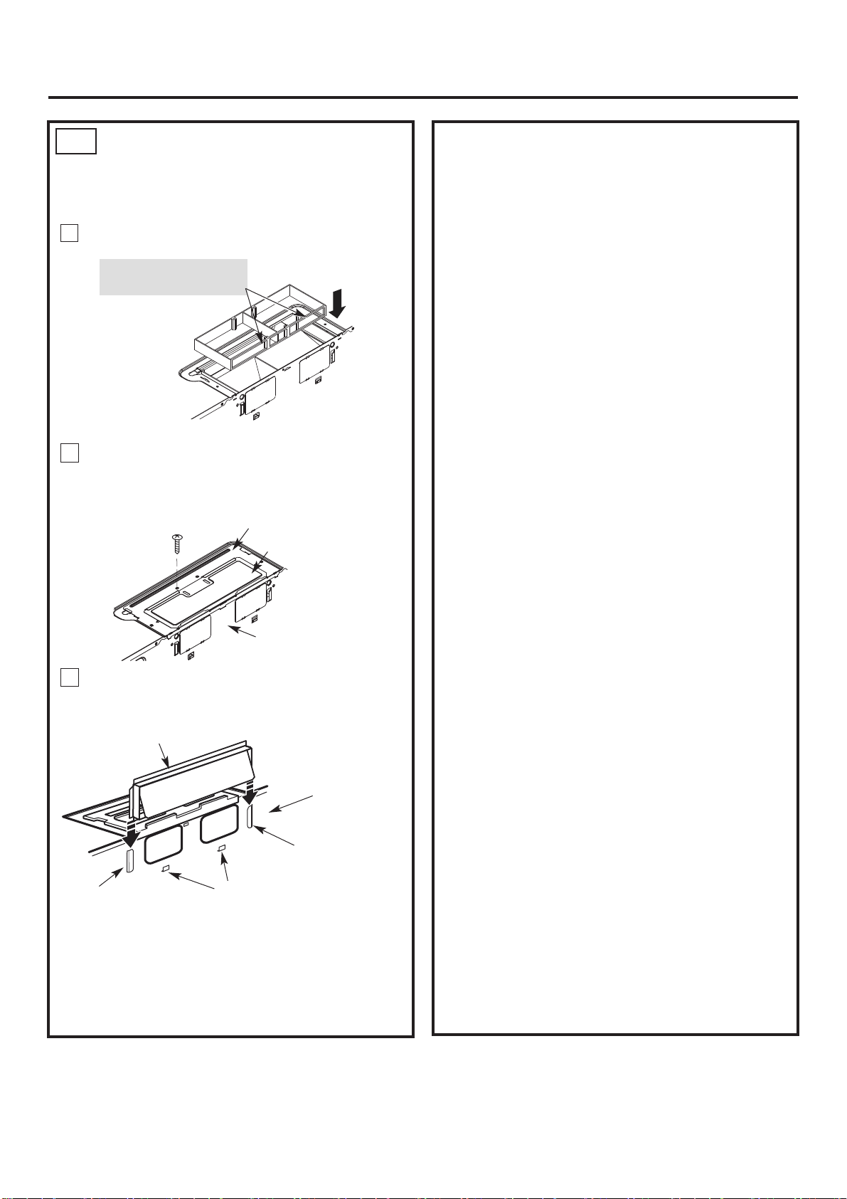
Instructions d’installation
B5.
ADAPTATION D’UN SYSTEME
DIRECTEUR D'AIR DU FOUR A
MICRO-ONDES POUR LA SORTIE
ARRIERE EXTERNE (suite)
Replacer le système directeur d'air dans
4
l'ouverture.
APRES : Ouvertures du
Système Directeur d'Air
vers l'Arrière
5
Fixer la plaque de ventilation du four à
micro-ondes avec la vis d'origine.
Plaque de Ventilation
Plaque du Couvercle
Intentionnellement
Arrière du Four à
micro-ondes
Fixer l'adaptateur d'évacuation à l'arrière du
6
four en le faisant coulisser dans les guides
situés en haut au centre sur l'arrière du four.
Adaptateur
Arrière du Four à
Micro-ondes
Guide
Guide
Pousser fermement jusqu'à ce qu'il soit dans les
languettes de verrouillage inférieures. Veiller à ce
que la charnière du volet soit installée de manière
à ce qu'elle se trouve en haut et que le volet oscille
librement.
Languettes de
Verrouillage
Laissé en Blanc
FR-17
Page 67
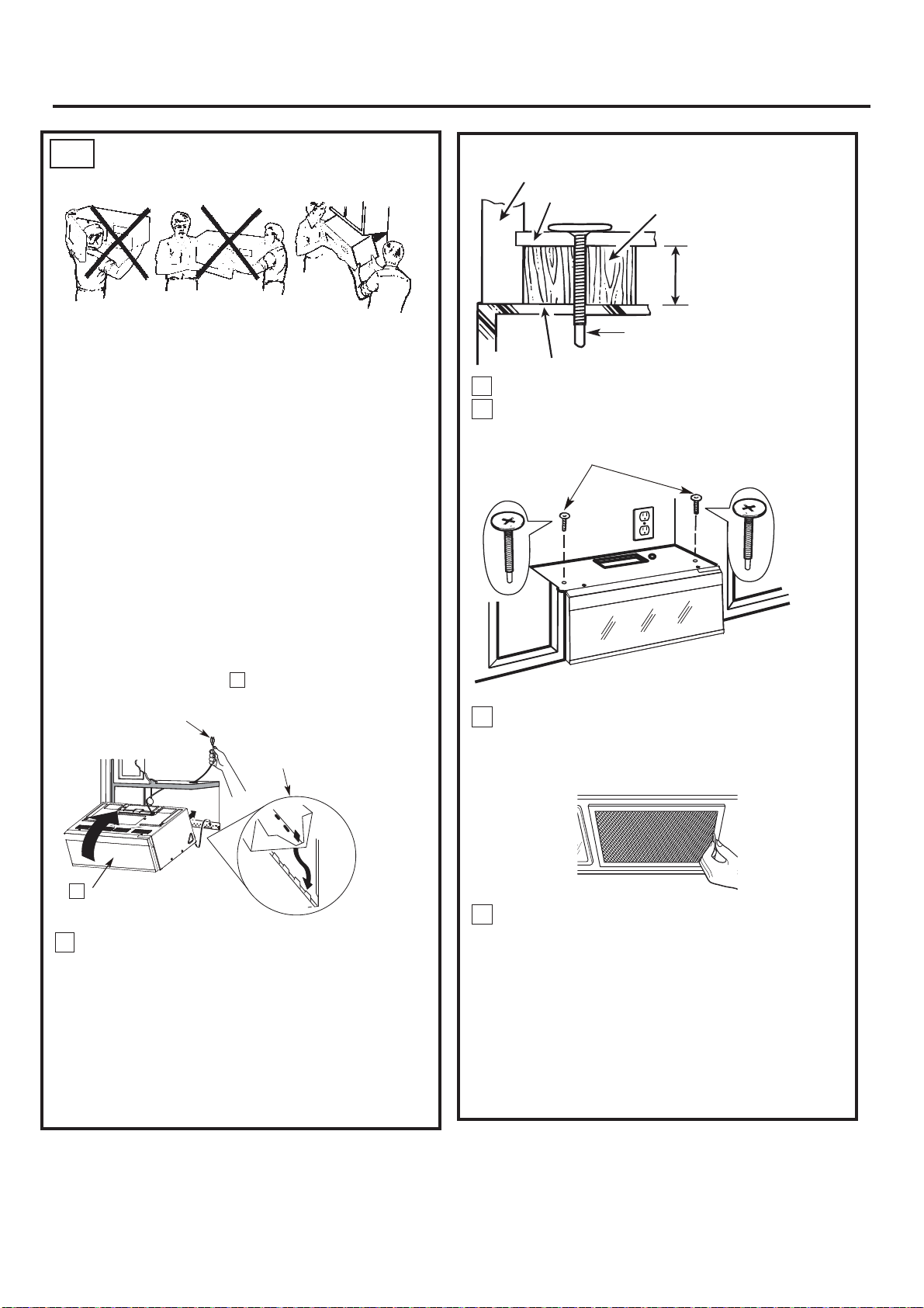
Instructions d’installation
B6.
INSTALLATION DU FOUR À
MICRO-ONDES
POUR VOTRE SÉCURITÉ ET POUR FACILITER
L’INSTALLATION, L’INSTALLATION DE CE FOUR
DOIT ÊTRE EFFECTUÉE PAR DEUX PERSONNES.
IMPORTANT: Ne pas saisir ou utiliser la poignée ou
l'écran thermique durant l'installation. Ne pas
retirer les entretoises en carton entre l'écran
thermique et la porte.
REMARQUE: Si vos armoires sont en métal,
installez un passe-fil en nylon autour de l’orifice du
cordon d’alimentation pour empêcher que le
cordon soit coupé.
REMARQUE: Si le four est installé sous une armoire
dotée d’un rebord avant, nous vous
recommandons d’utiliser des entretoises.
IMPORTANT: Si vous n’utilisez pas d’entretoises,
des dommages peuvent être causés au boîtier au
moment de resserrer les vis.
REMARQUE: Lors de l’installation
du four à micro- ondes, faites
passer le cordon d’alimentation à
travers le trou situé dans le fond de
l’armoire supérieure. Gardez-le bien
serré durant les étapes 1 à 3. Ne
coincez pas le cordon ou
ne soulevez pas le four en tirant sur
le cordon.
1
Soulevez le four à microondes, penchez-le vers l’avant
et accrochez les fentes du bord
inférieur de l’arrière du four sur
les quatre languettes
inférieures de la plaque de
montage.
Avant de l’armoire
Étagère inférieure de l’armoire
Entretoise
Vis à auto-alignement
Dessus du four à micro-ondes
Fixez le four à micro-ondes à l’armoire supérieure.
4
Insérez deux vis à auto-alignement à travers
5
Équivalent à la
profondeur du
rebord de l’armoire
les trous de l’armoire supérieure. Faites faire
deux tours complets à chaque vis.
Serrez les deux vis de chaque côté dans le
6
dessus du four à micro-ondes. (Tout en serrant
les vis, soulevez l’avant du four à micro-ondes et
poussez-le contre le mur et l’armoire supérieure.)
2
Relevez le devant du four
pour le mettre contre le
dessous de l’armoire.
Insérez une vis à auto-alignement dans le trou
3
situé au centre de l’armoire supérieure. Fixez
temporairement le four en faisant faire au moins
deux tours complets à la vis après que les filets
aient été engagés. (Elle sera
complètement resserrée plus tard.)
Assurez-vous que le cordon d’alimentation est
bien serré. Faites attention de ne pas le coincer,
particulièrement au moment d’installer le four
sous l’armoire.
Installez les filtres. Consultez le Manuel de
7
l’utilisateur emballé avec le four.
IMPORTANT: Retirer les entretoises en carton
entre l'écran thermique et la porte.
FR-18
Page 68
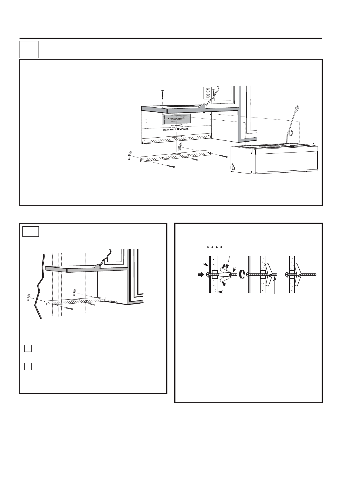
Instructions d’installation
ÉVACUATION À L’EXTÉRIEUR PAR LE DESSUS (Conduit vertical)
C
VUE D’ENSEMBLE DE L’INSTALLATION
A1. Fixation de la plaque de montage au mur
A2. Préparation de l’armoire supérieure
A3. Ajustement du ventilateur
A4. Vérification du fonctionnement du registre
A5. Installation du four à micro-ondes
A6. Ajustement de l’adaptateur d’évacuation
A7. Connexion au conduit
REMARQUES IMPORTANTES :
• Assurez-vous que les vis du
moteur du ventilateur et de la
plaque du ventilateur sont
solidement vissées lorsque vous
les remettez en place. Cela évitera
les vibrations excessives.
• Assurez-vous que les fils du
moteur sont bien acheminés, fixés
et qu’ils ne sont pas coincés.
O
NT T
TA
OR
P
M
RY I
E
V
IT IS
:
TE
O
N
NS
IO
RECT
I
D
THE
W
O
LL
ND FO
A
D
REA
S
ION
CT
TRU
NS
I
N
O
I
T
LLA
A
NST
I
IN THE
IS
H
T
ITH
W
DING
CEE
O
R
P
RE
O
F
E
B
.
TE
A
EMPL
T
L
L
A
REAR W
ottom
b
e
th
n
o
ti
i
s
o
p
o
t
s
ve
r
e
s
e
t
a
l
p
m
Te
ll
Wa
r
a
e
R
s
hi
T
t
s
hau
tal ex
n
o
z
i
or
h
e
h
t
te
ca
o
d to l
an
e
t
a
l
p
g
n
ti
n
u
mo
t.
e
utl
o
itioned
os
is p
late
p
em
t
e
at th
h
k t
ec
ch
to
l
ve
e
l
a
e
Us
.
1
y.
l
e
at
r
cu
ac
or
eft
l
e
n th
o
d
estu
n
t o
as
e
t l
rk a
a
m
nd
e a
t
oca
2. L
.
e
in
rl
e
nt
e
the c
f
o
de
right si
wood
ne
o
t
as
e
l
t
a
use
o
t t
an
rt
po
im
is
It
t
h
e weig
h
t t
or
o supp
tud t
s
n a
y i
l
rm
fi
d
te
n
u
o
w m
e
cr
s
ed
ac
ysp
evenl
l,
a
ion
addit
k two
ar
M
.
ave
w
o
icr
m
e
fth
o
lts.
o
b
gle
g
o
t
ied
l
upp
s
e
th
or
f
s
ation
c
o
l
s
i
there
e
r
he
W
.
ons
i
t
ca
lo
d
arke
m
e
th
n
i
s
ole
h
ll
i
r
D
3.
s
le
o
h
For
.
ws
e
r
d sc
woo
or
f
le
o
h
"
6
1
/
3
a
ill
dr
d,
u
a st
r
les fo
o
h
"
8
/
5
l
ril
d, d
tu
s
a
ith
w
p
u
e
in
l
not
o
d
hat
t
.
ts
l
bo
le
gg
o
t
E
LAT
G P
IN
T
UN
HE MO
L T
NSTAL
T I
DO NO
.
E
IM
T
HIS
T
AT
wall.
ar
e
r
e
h
tm
o
te fr
la
p
m
te
the
ove
m
e
R
.
4
r
ou
y
or
k f
o
tion bo
c
u
r
st
n
I
tion
a
ll
sta
n
I
e
h
t
w
ie
v
e
R
5.
.
on
i
t
tua
i
n s
o
i
at
ll
sta
in
a
l
ltar
u
s
con
ra
apa
joh
a
l
ltaa
e
vu
e
l
r
a
D
ol.
ñ
a
p
s
E
n
e
n
ó
rsi
e
v
e
n th
i
s
le
o
h
th
wi
align
o
s t
rk hole
a
d m
n
a
e
cat
Lo
te.
a
pl
g
tin
n
u
o
m
:
ANT
RT
O
P
IM
F
O
E
SID
ER
ON EITH
D
STU
E
ON
ST
EA
L
T
E A
T
A
LOC
.
LINE
R
E
ENT
C
HE
T
Y
AL, EVENL
N
R 2 ADDITIO
ONFO
TI
A
C
HE LO
T
K
AR
M
E
T
PLA
ING
MOUNT
N THE
I
TS
L
BO
LE
OGG
T
D
CE
A
P
S
.
EA
R
A
.
e
n
d li
e
tt
o
d
e
th
g
on
l
a
ate
pl
m
e
ll t
a
w
r
a
e
r
he
t
Trim
E
EDG
TO
"
3/8
12"
4"
L
M
I
L
T
MA
SP
AR
.
e
n
li
d
e
t
ot
d
he
t
long
a
e
mplat
e
t
l
al
w
r
ea
he r
t
Trim
the
n
es i
l
ho
h
it
w
gn
li
a
to
es
l
ho
k
r
a
m
nd
a
ate
c
o
.
e
t
a
l
i
p
nu
g
n
t
om
:
T
N
A
T
POR
OF
E
D
I
S
R
THE
N EI
O
D
U
EST
ON
T
S
A
E
L
AT
E
T
OCA
E.
N
I
L
R
E
NT
E
C
HE
Y
NL
E
, EV
L
A
N
O
ITI
DD
A
2
FOR
N
IO
CAT
LO
HE
T
RK
E
T
LA
P
G
IN
T
OUN
M
E
H
T
IN
S
OLT
B
GGLE
TO
D
CE
A
.
A
E
C1.
FIXATION DE LA PLAQUE DE
MONTAGE AU MUR
Fixez la plaque au mur à l’aide des boulons à
ailettes. Vous devez utiliser au moins une vis à bois
pour fixer la plaque à un montant.
Enlevez les écrous à ailettes des boulons.
1
Insérez les boulons dans la plaque de montage à
2
travers les trous dans le gypse et réassemblez les
écrous à ailettes, à 3/4 po (19 mm) sur chaque
boulon.
Pour utiliser les boulons à ailettes :
Espace pour les ailettes
supérieur à l’épaisseur du
mur
Plaque de
montage
Placez la plaque de montage contre le mur et
3
insérez les écrous à ailettes dans les trous du
mur pour fixer la plaque.
REMARQUE: Avant de resserrer les boulons à
ailettes et la vis à bois, assurez-vous que la plaque
est bien centrée sous l’armoire et que les languettes
de la plaque de montage touchent le dessous de
l’armoire lorsque vous poussez la plaque contre le
mur.
ATTENTION: Faites attention de ne pas vous pincer
les doigts entre l’arrière de la plaque de montage et
le mur.
4
Serrez tous les boulons. Tirez sur la plaque pour
faciliter le serrage des boulons.
Écrou à ailettes
Boulon à
ailettes
Mur
Extrémité du boulon
FR-19
Page 69
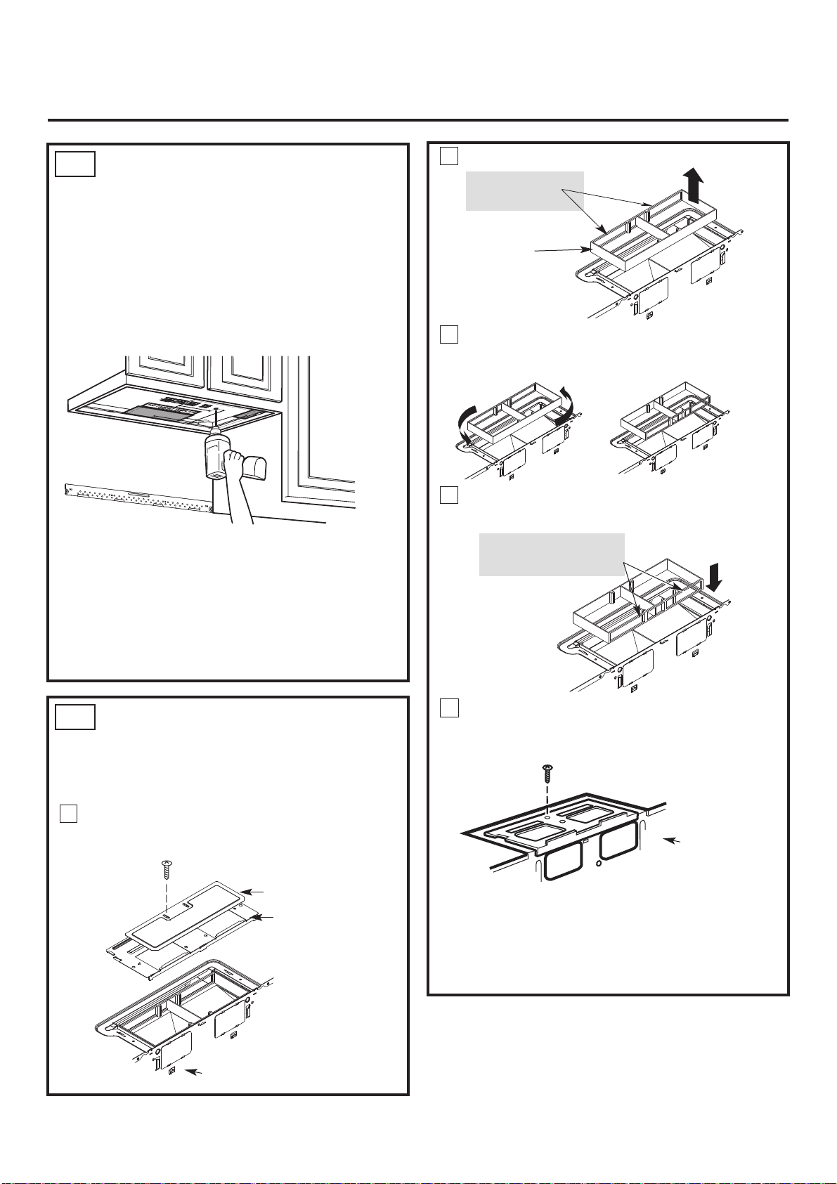
Instructions d’installation
C2.
UTILISATION DU GABARIT
POUR ARMOIRE SUPÉRIEURE
POUR LA PRÉPARATION DE
L’ARMOIRE SUPÉRIEURE
Vous devez percer des trous pour les vis de soutien
supérieures, ainsi qu’un trou suffisamment grand
pour y faire passer le cordon d’alimentation et une
ouverture assez grande pour l’adaptateur
d’évacuation.
Retirer délicatement le système directeur d'air.
2
Avant :
Ouvertures
Vers l'Avant
Système
Directeur d’Air
Faire pivoter le système directeur d'air de 180°
3
dans le sens inverse aux aiguilles d'une montre.
Avant Rotation Après Rotation
Replacer le système directeur d'air dans
4
l'ouverture.
• Lisez les instructions sur le GABARIT POUR
ARMOIRE SUPÉRIEURE.
• Collez-le sous l’armoire supérieure à l’aide de
ruban adhésif.
• Percez les trous, en suivant les directives du
GABARIT POUR ARMOIRE SUPÉRIEURE.
ATTENTION: Portez des lunettes de sécurité lorsque
vous percez des trous dans le fond de l’armoire.
C3.
ADAPTATION D'UN SYSTEME
DIRECTEUR D'AIR POUR LE
FOUR A MICRO-ONDES POUR
LA SORTIE ARRIERE EXTERNE
Retirer la vis qui maintient la plaque d’aération
1
sur le four à micro-ondes. Retirer la plaque du
couvercle.
Plaque du Couvercle
Plaque de Ventilation
APRES : Ouvertures du
Système Directeur d'Air
vers l'Arrière
Remettre la plaque de ventilation en place avec
5
la vis retirée à l'étape 1. Vérifier que la vis soit
bien serrée.
Arrière du Four à
micro-ondes
Arrière du Four à
micro-ondes
FR-20
Page 70
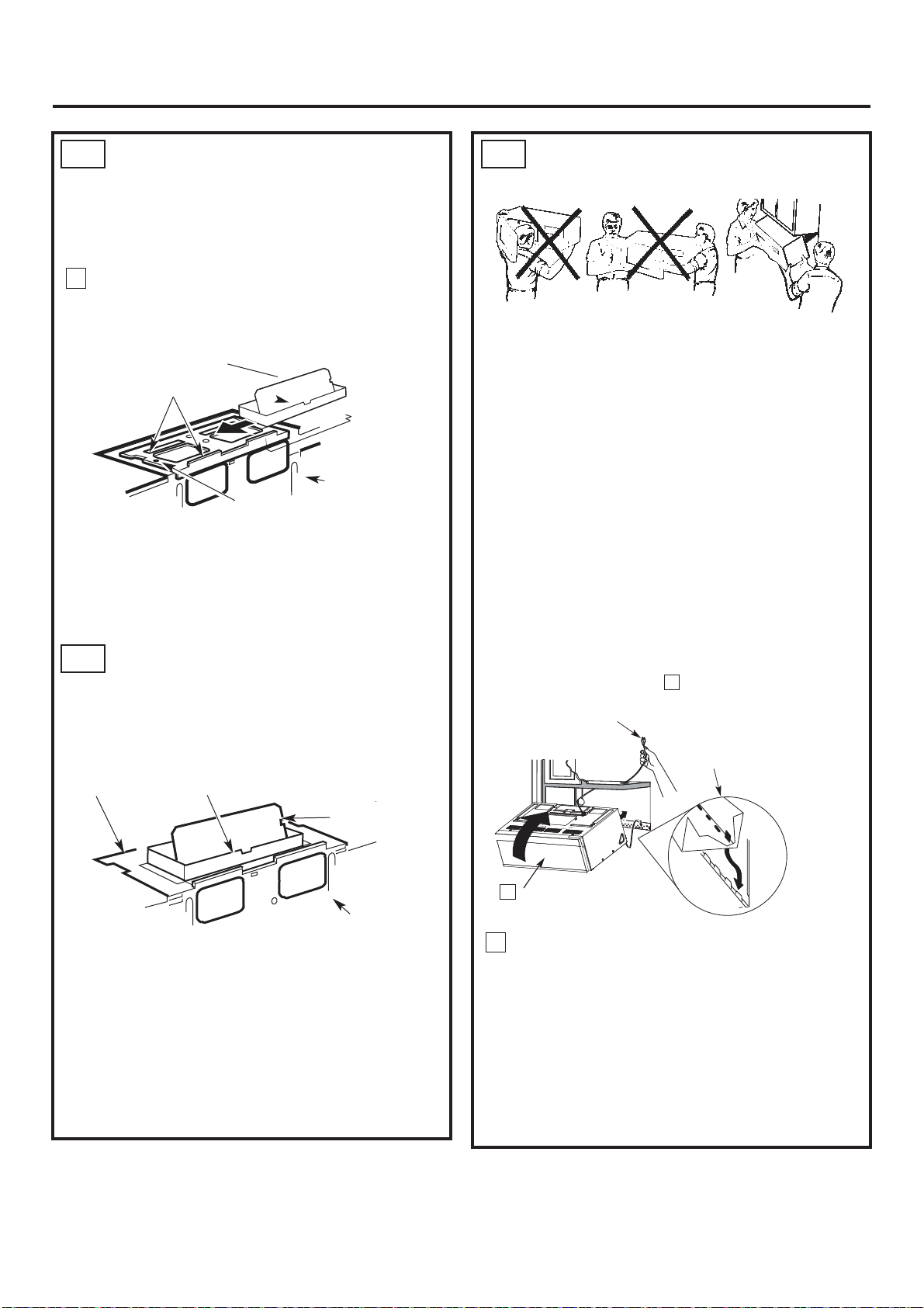
Instructions d’installation
C3.
ADAPTATION DU
VENTILATEUR DU FOUR À
MICRO-ONDES POUR
L’ÉVACUATION À L’EXTÉRIEUR
PAR LE DESSUS (suite)
6
Fixez l’adaptateur d’évacuation en haut du
plaque du ventilateur en le coulissant dans les
guides situés, à la partie supérieure arrière du
plaque du ventilateur.
Adaptateur
Guide
Arrière du four à
micro-ondes
Fentes de
blocage
Insérez-le jusqu’à ce qu’il soit dans les fentes de
blocage inférieures. Assurez-vous que la
charnière du registre est installée et que le
registre bouge librement.
C3.
VÉRIFICATION DU
FONCTIONNEMENT DU
REGISTRE
Plaque du
ventilateur
Adaptateur de
conduit d’évacuation
C5.
INSTALLATION DU FOUR À
MICRO-ONDES
POUR VOTRE SÉCURITÉ ET POUR FACILITER
L’INSTALLATION, L’INSTALLATION DE CE FOUR
DOIT ÊTRE EFFECTUÉE PAR DEUX PERSONNES.
IMPORTANT: Ne pas saisir ou utiliser la poignée ou
l'écran thermique durant l'installation. Ne pas
retirer les entretoises en carton entre l'écran
thermique et la porte.
REMARQUE: Si vos armoires sont en métal,
installez un passe-fil en nylon autour de l’orifice du
cordon d’alimentation pour empêcher que le
cordon soit coupé.
REMARQUE: Si le four est installé sous une armoire
dotée d’un rebord avant, nous vous
recommandons d’utiliser des entretoises.
IMPORTANT: Si vous n’utilisez pas d’entretoises,
des dommages peuvent être causés au boîtier au
moment de resserrer les vis.
REMARQUE: Lors de
l’installation du four à microondes, faites passer le cordon
d’alimentation à travers le trou
situé dans le fond de l’armoire
supérieure. Gardez-le bien serré
durant les étapes 1 à 3. Ne
coincez pas le cordon ou
ne soulevez pas le four en tirant
sur le cordon.
Soulevez le four à micro-
1
ondes, penchez-le vers l’avant
et accrochez les fentes du bord
inférieur de l’arrière du four sur
les quatre languettes
inférieures de la plaque de
montage.
Registre
Arrière du
four à
micro-ondes
• Assurez-vous que le ruban adhésif qui retient
le registre a été enlevé et que le registre bouge
librement avant d’installer le four.
• Vous devrez effectuer les ajustements
nécessaires pour vous assurer que le conduit
du four est bien aligné sur le
conduit d’évacuation du domicile après
l’installation du four.
FR-21
2
Relevez le devant du four
pour le mettre contre le
dessous de l’armoire.
3
Insérez une vis à auto-alignement dans le trou
situé au centre de l’armoire supérieure. Fixez
temporairement le four en faisant faire au moins
deux tours complets à la vis après que les filets
aient été engagés. (Elle sera
complètement resserrée plus tard.)
Assurez-vous que le cordon d’alimentation est
bien serré. Faites attention de ne pas le coincer,
particulièrement au moment d’installer le four
sous l’armoire.
Page 71
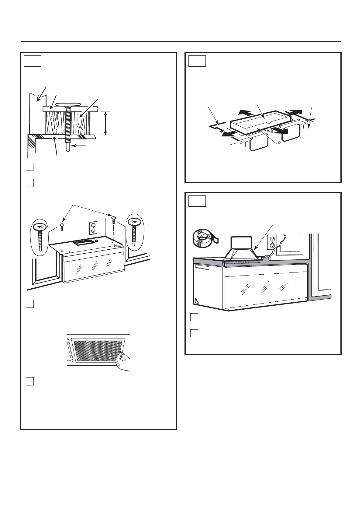
Instructions d’installation
C5.
INSTALLATION DU FOUR À
MICRO-ONDES (suite)
Avant de l’armoire
Étagère inférieure de l’armoire
Entretoise
Équivalent à la
profondeur du
rebord de l’armoire
Vis à auto-alignement
Dessus du four à micro-ondes
Fixez le four à micro-ondes à l’armoire supérieure.
4
5
Insérez deux vis à auto-alignement à travers
les trous de l’armoire supérieure. Faites faire
deux tours complets à chaque vis.
C6.
AJUSTEMENT DE
L’ADAPTATEUR D’ÉVACUATION
Ouvrez l’armoire supérieure et ajustez l’adaptateur
d’évacuation pour le relier au conduit d’évacuation
du domicile.
Plaque du ventilateur
C7.
CONNEXION AU CONDUIT
Registre
Pour un ajustement de
l’avant à l’arrière ou de
côté à côté, glissez
l’adaptateur d’évacuation
tel que requis
Conduit du domicile
Arrière du four
à micro-ondes
6
Serrez les deux vis de chaque côté dans le
dessus du four à micro-ondes. (Tout en serrant
les vis, soulevez l’avant du four à micro-ondes et
poussez-le contre le mur et l’armoire supérieure.)
7
Installez les filtres. Consultez le Manuel de
l’utilisateur emballé avec le four.
IMPORTANT: Retirer les entretoises en carton
entre l'écran thermique et la porte.
Tirez sur le conduit du domicile pour le raccorder
1
à l’adaptateur d’évacuation.
Scellez les joints du conduit d’évacuation à l’aide
2
de ruban adhésif en toile convenant à des
températures élevées.
FR-22
Page 72
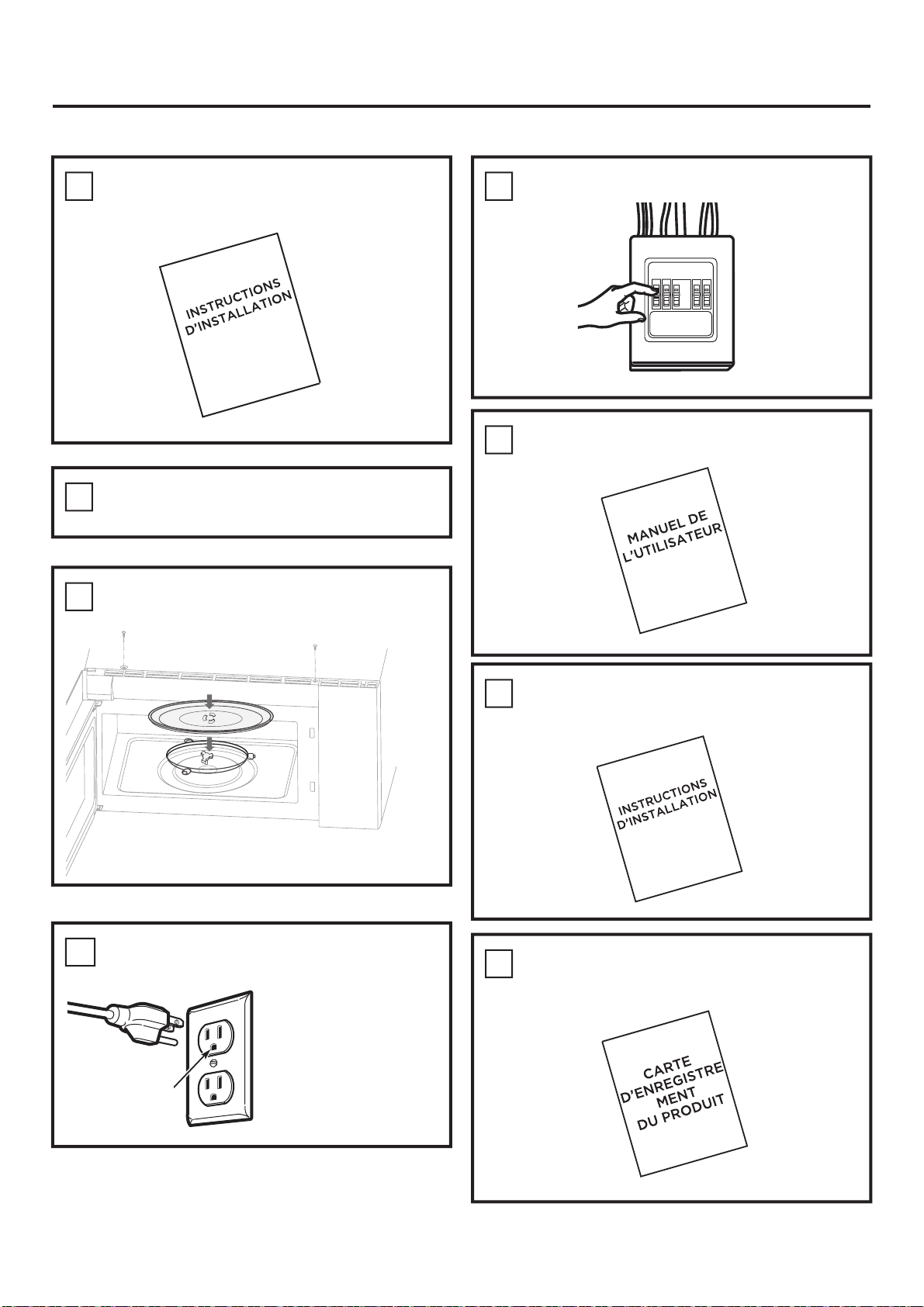
Instructions d’installation
AVANT D’UTILISER VOTRE FOUR À MICRO-ONDES
Assurez-vous que le four à micro-ondes a été
1. 5.
installé conformément aux instructions.
6.
2.
Enlevez tout le matériel d’emballage du four
à micro-ondes.
3.
Installez le plateau tournant et la plateau en
verre dans le four à micro-ondes.
Réinstallez le fusible ou réenclenchez le
disjoncteur du panneau de distribution principal.
Lisez le manuel d’utilisation et d’entretien.
Branchez le cordon d’alimentation séparée et
4.
dédiée sur une prise de courant réservée de 15
à 20 A.
Assurez-vous
qu’une mise à la
terre appropriée
est en place
avant toute
utilisation.
CONSERVEZ LES INSTRUCTIONS
7.
D’INSTALLATION POUR VOTRE INSPECTEUR
LOCAL.
Remplissez la carte d’enregistrement du
8.
produit.
FR-23
 Loading...