

Page 1
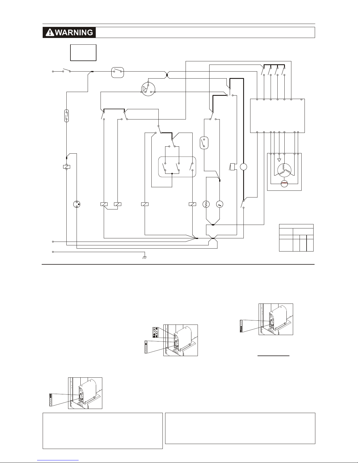
WIRING DIAGRAM
If grounding wires, screws or clips used to complete a path to ground are removed
for service, they must be returned to their original position and properly fastened.
Certain internal parts are intentionally NOT grounded and may present a risk of
electric shock only during servicing. Do not contact the following parts while the
appliance is energized: pump, drive motor and electronic control boards.
This information is intended for use by technicians possessing
adequate background of electrical, electronic and mechanical
experience. Any attempt to repair a major appliance may result in
personal injury and property damage. The manufacturer or seller
cannot be responsible for the interpretation of this information, nor
can it assume any liability in connection with its use.
IMPORTANTIMPORTANT SAFETY NOTICE
TECH SHEET - RETAIN FOR SERVICE TECHNICIAN
Disconnect from Electrical Supply Before Servicing Washer.
134390200 0402
Motor Will Not Run
Timer/off
Drawer/open
Door/open
SWITCH
POSITION
CIRCUIT
WATER TEMP SWITCH
H/C
X X
X
W/C
XXX
C/C
XW/W
1 - 3 1 - 5
2 - 4W/R
C10.10 (D)
C10.9 (E)
C10.6 (C)
C10.1 (B)
C10.2 (A)
C10.5 (TM)
C10.8 (F)
SIGNAL
DOOR
LOCK
COIL
DOOR
LAMP
TIMER
MOTOR
C6.5 (AC)
C6.6 (AC)
C6.2 (P2)
C6.3 (P3)
C6.1 (P1)
C6.4
C10.3 (T2)
C10.4 (T1)
T
B
RINSE
WATER
CYCLE
SIGNAL
TIMER
DIRECT
RINSE
WATER
WASH
WATER
WASH
WATER
BLK/WHT
BLK
2
2
1
1
WHT
WHT/RED
BLUE
RED/YEL
ORG
BROWN
RED/BLK
TAN/WHT
YEL/WHT
YELLOW
YEL/RED
BLK
BLK/RED
YEL/BLK
AQUA
TAN/BLK
ORG/WHT
TAN
BLUE
YEL
BLUE
PINK/BLK
WHT/RED
BROWN
RED
YEL/BLK
BLU/WHT
BLU/WHT
B
2B
4
2
MOTOR CONTROL
B
T
10
2
5
3
1 4
8
T
12 B
T
0T 0C
BLEACH
SOFTENER
TEMP
SWITCH
HOTCOLD
#4
L1
BLEACH SOFTENER
MS
4.4
2.1
WATER
VALVES
DISPENSER
VALVES
WATER LEVEL
PRESSURE
SWITCH
2.2
4.3
DOOR
LOCK
SWITCH
LINE SWITCH
PUSH-PULL
DISPENSER
DRAWER
REED SWITCH
7B5B3B1B
6T
7C5C3C1C
6C
1
2
3
M
EXTRA
RINSE
SWITCH
PUMP
MOTOR
T
GRAY
B14
#2
#5
#6
WAX
MOTOR
PTC
+t
2
1
ORG/BLK
GREEN
6 53
24
1
TACHO-
GENERATOR
T
MOTOR
WINDING
1.
Advance the timer knob to the drain
increment. If the drain pump does not run,
check household safety circuit. If the drain
pump runs go to step 2.
2.
Turn the water off to the washer. Remove
electrical power from the washer and
remove the back panel. Remove the motor
drive belt. Reconnect electrical power and
set the timer to the start of the Regular wash
cycle and pull the knob out. If motor does
not rotate, check for a poor connection in the
timer line switch or door lock switch. If good,
and moto r does not run go to step 3.
3.
Remove the six pin plug from the speed
control unit. Measure the voltage between
pins 5 and 6 on the harness. If the meter
reads 0 check the connection in the timer
line switch or door lock. If the meter
reads 120 Vac go to step 4.
CHECK FOR POWER:
CHECK FOR MOTOR MOVEMENT:
MEASURE VOLTAGES:
4.Set the timer to the Heavy Wash position of
the Regular wash cycle. Remove the ten pin
plug from the speed control unit. Measure
the voltage between pins 1, 2, 6 and 10 of
the ten pin plug to pin 5 of the 6 pin plug on
the harness. The voltage at pins 2, 6, and
10 should read 120 Vac and 0 Vac at pin 1.
If not, check timer contacts 1C to 1B, 5C to
5B, and 7C to 7B for closed contacts, and
3C to 3B for open contacts. If the voltage
readings are correct, go to step 5.
5.
6.Remove the 6 pin plug from the sp eed
control unit. Measure the resistance
between pins 1 and 2, 2 and 3, and 3 and 1
of the speed control unit. If the meter reads
other than 3 Meg ohms ± 10%, replace the
speed control board.
MEASURE RESISTANCES:
Check the fuse on the speed control board.
If the fuse is open, replace the speed control
board. If good, go to step 6.
7.Remove electrical power from the washer.
With an ohmmeter check the resistance
between pins 1 and 2, 2 and 3, and 3 and 1
of the six pin plug on the harness. If the
meter reads other than 2.6 ohms ± 7%,
replace the motor.
Quick Facts
•The timer motor will not run continuously.
The speed control unit controls the timer
motor and advances the timer when needed.
•In some tumble modes, the tub may not
tumble for the first 16 to 20 seconds after
start-up.
•Extremely low water pressure may cause
tub rotation to stop until WLC satisfied.
Speed
Control
Speed
Control
Speed
Control
GRN
WHT
WHT
WHT
#1
#7
N
GND
CABINET
CHASSIS
#3
6
1
6
1
5 10
1 6
6
1
Not on all models
*
*
PINK
Page 2
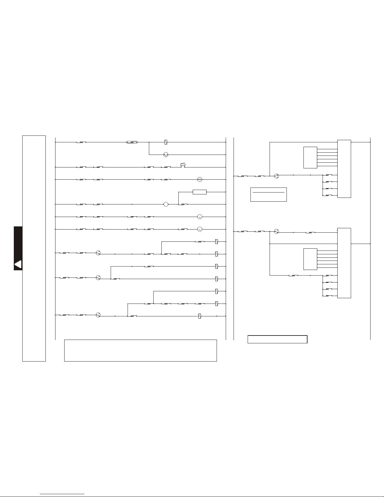
If grounding wires, screws or clips used to complete a path to ground are removed for service, they
must be returned to their original position and properly fastened. Certain internal parts are intentionally
NOT grounded and may present a risk of electric shock only during servicing. Do not contact the
following parts while the appliance is energized: pump, drive motor and electronic control boards.
TIMER
TIMER
TIMER
TIMER
TIMER
TIMER
TIMER
TIMER
DISPENSER DRAWER
REED SWITCH
DOOR LOCK
COIL
DOOR LAMP WON'T LIGHT OR
DOOR LOCK SOLENOID WON'T ENERGIZE
L1 N
0T
0T
0T
0T
0T
0T
0T
0T
2 1
4.4 2.1
0C
0C
0C
0C
0C
0C
0C
0C
21
This information is intended for use by persons having electrical and mechanical training and a level of
knowledge of these subjects generally considered acceptable in the appliance repair trade. The
manufacturer or seller can not be responsible, nor assume any liability, for injury or damage of any kind
arising from the use of this data.
NOTE: DASHED LINES INDICATE INTERNAL TIMER JUMPER WIRES.
IMPORTANT
WARNING
!
DIAGNOSTIC STRIP CIRCUITS
134390200 0402
SPEED
CONTROL
C10.5 C6.5
DOOR
LOCK
DOOR
LOCK
DOOR
LOCK
DOOR
LOCK
DOOR
LOCK
DOOR
LOCK
DOOR
LOCK
TIMER BUZZER
ON / OFF
TIMER
TIMER
TIMER
TIMER
TIMER
TIMER
TIMER TEMP
SWITCH
TIMER TEMP
SWITCH
TIMER
MOTOR
WAX
MOTOR
PUMP
MOTOR
BUZZER
IF NO END-OF-CYCLE SIGNAL (BUZZER)
IF DOOR LOCK OPENS DURING SPIN
IF TIMER WON'T ADVANCE
IF WATER PUMP DOES NOT WORK
2.2
2.2
2.2
2.2
2.2
2.2
2.2
TIMER
12C
12C
14C
10C
12C
8C
8C
8C 1 10T 2
2C
4C
TIMER
TIMER
TIMER
TIMERTIMER
TIMER
TIMER
WATER LEVEL
SWITCH
WATER LEVEL
SWITCH
WATER LEVEL
SWITCH
4.3
4.3
4.3
4.3
4.3
4.3
4.3
2C 8B4C
4C
2C
12C
12B
12T
DOOR LAMP
14B
10B
12T
8T
8B
8B 3 10C 4
2B
4B
MS
TIMER
14C
14B
HOT WATER
SOLENOID
COLD WATER
SOLENOID
HOT WATER
SOLENOID
COLD WATER
SOLENOID
BLEACH
SOLENOID
COLD WATER
SOLENOID
BLEACH
SOLENOID
SOFTENER
SOLENOID
TEMP
SWITCH
TEMP
SWITCH
TIMER
IF NO HOT, WARM OR COLD WATER DURING WASH FILL (DETERGENT)
IF NO WARM OR COLD WATER DURING RINSE FILL (SOFTENER)
IF NO COLD WATER DURING RINSE FILL (BLEACH)
2
5
6C
1
2
2
2
3
3
3
1
1
1
4
1
6T
2
M
PTC
+t
MOTOR
(PHASE 1) 3
(PHASE 2) 2
(PHASE 3) 1
(TACH) 5
(TACH) 6
(GND) 4
IF NO MOTOR ROTATION DURING FILL OR AGITATION
OR WASH LAMP WON’T LIGHT
IF NO MOTOR ROTATION DURING SPIN
OR RINSE LAMP OR FINAL SPIN LAMP WON’T LIGHT
L1 N
SPEED
CONTROL
C6.6
(AC)
C6.6
(AC)
C6.5
(AC)
C6.5
(AC)
MOTOR
C6.1 (P1)
C6.2 (P2)
C6.3 (P3)
C10.3 (T2)
C10.4 (T1)
C6.4 (GND)
(PHASE 1) 3
(PHASE 2) 2
(PHASE 3) 1
(TACH) 5
(TACH) 6
(GND) 4
SPEED
CONTROL
C10.2 (A)
C10.1 (B)
C10.6 (C)
C10.10 (D)
TIMERTIMER
12C
14C12T
TIMER
TIMER
TIMER
TIMER
1C
3C
5C
7C
1B
3B
5B
7B
TIMER CONTACTS 1, 3, 5 AND 7:
REFER TO TIMER CHART FOR THE
MOTOR CONTROL CODE AND
MACHINE FUNCTION.
C10.2 (A)
C10.1 (B)
C10.6 (C)
C10.10 (D)
WATER LEVEL
SWITCH
2
3
1
TIMER
0T 0C
DOOR
LOCK
TIMER TIMER
2.2 4.3
12T 14C
TIMER
TIMER
TIMER
TIMER
1C
3C
5C
7C
1B
3B
5B
7B
4C
TIMERTIMER
2C 4T
2
3
1
TIMER
0T 0C
DOOR
LOCK
2.2 4.3
WATER LEVEL
SWITCH
C10.8 (F)
C10.9 (E)
C6.1 (P1)
C6.2 (P2)
C6.3 (P3)
C10.3 (T2)
C10.4 (T1)
C6.4 (GND)
TIMER
0T 0C
DOOR
LOCK
TIMER EXTRA
RINSE
TIMER PUMP
MOTOR
2.2 14C 1
12C
4.3 14T 212T
IF WATER PUMP DOES NOT WORK IN EXTRA RINSE
1
2
M
 Loading...