

Frigidaire GLMB186K Installation Instructions Manual
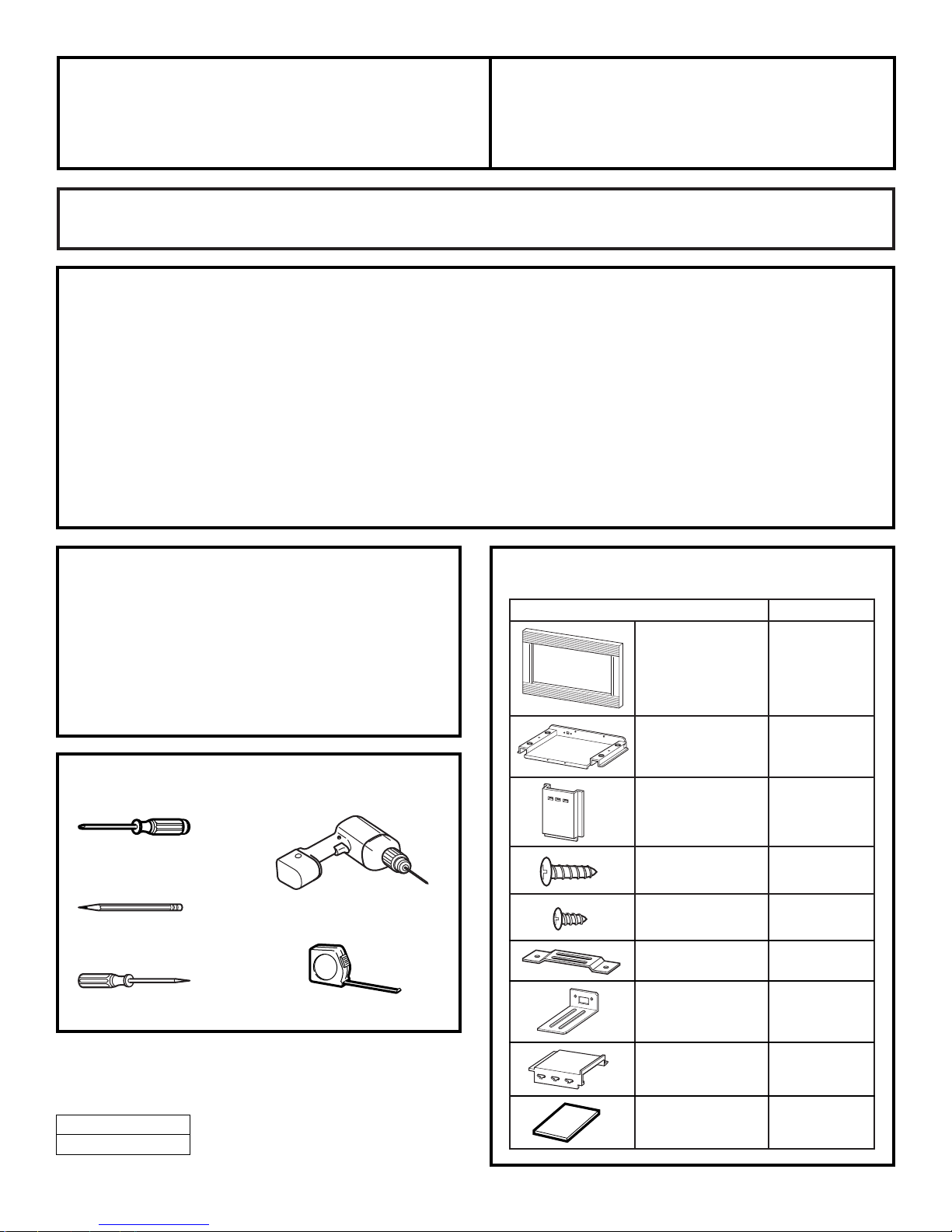
PART QUANTITY
Trim Frame 1
Bottom Duct 1
Side Duct 1
1” Screws 6
(4 required, 2 extra)
1
⁄2” Screws 15
(11 required, 4 extra)
Anti-Tip Bracket 1
Bottom Bracket 1
Upper Duct 1
Template 1
Questions? In the U.S., call 1-800-944-9044. In Canada, call 1-866-213-9397 (English),
1-800-669-4606 ext. 8199 (French).
Visit our Website at:
www.frigidaire.com
READ CAREFULLY.
KEEP THESE INSTRUCTIONS
.
Installation Built-In Trim Kits
Instructions
82-1827 and 82-1830
Phillips screwdriver
Pencil
Tape measure
Awl or punch
Drill with
7
⁄64″ bit or #35
1
164D3370P160
49-40169-1
P/N 316137209 Rev. A
Printed in Korea (05-01 JR)
BEFORE YOU BEGIN
Read these instructions completely and carefully.
•
IMPORTANT
–
Save these
instructions for local inspector’s use.
•
IMPORTANT
–
Observe all
governing codes and ordinances.
•
Note to Installer
–
Be sure to leave these
instructions with the Consumer.
•
Note to Consumer
–
Keep these
instructions for future reference.
• Unplug the microwave oven before attempting
installation of this kit.
• Skill level – Installation of this appliance requires basic
mechanical and electrical skills.
• Completion time – 1-3 hours
• Proper installation is the responsibility of the installer.
• Product failure due to improper installation is not
covered under the Warranty.
• This kit is UL and CUL listed for installation alone or
over any Frigidaire single electric wall oven.
FOR YOUR SAFETY:
WARNING
–
Before beginning the
installation, switch power off at service panel and lock
the service disconnecting means to prevent power
from being switched on accidentally. When the service
disconnecting means cannot be locked, securely fasten
a prominent warning device, such as a tag, to the
service panel.
TOOLS YOU WILL NEED
PARTS INCLUDED

2
Installation Instructions
CUTOUT DIMENSIONS
On 27″ (68.6 cm) models, allow 1″ (2.5 cm) at the top,
11
⁄16″ (1.75 cm)on the sides and 13⁄8″ (3.5 cm)at the
bottom for overlap of the Trim Frame over the edges
of the cutout.
On 30″ (76.2 cm) models, allow 1″ (2.5 cm) at the top,
2
3
⁄16″ (5.6 cm) on the sides and 13⁄8″ (3.5 cm) at the
bottom for overlap of the Trim Frame over the edges
of the cutout.
1
.
* Min. depth with receptacle outside cabinet 19
1
⁄2″ (49.5 cm).
Min. depth with receptacle inside cabinet 22″ (56 cm).
Depth
Height
3″ Min.
(7.6 cm)
Width
Models 27″ 30″
(68.6 cm) (76.2 cm)
Height 16
3
⁄4″ 163⁄4″
(42.5 cm) (42.5 cm)
Width 25
1
⁄2″ 251⁄2″
(6.5 cm) (6.5 cm)
Depth (min.)* 19
1
⁄2″or 22″ 191⁄2″or 22″
(49.5 cm or (49.5 cm or
56 cm) 56 cm)
INSTALL BOTTOM BRACKET
AND BOTTOM DUCT
Disconnect the microwave oven before proceeding
with the installation.
Fasten the bottom bracket to the bottom duct by
using two
1
⁄2″screws.
Remove any loose items inside the microwave oven,
including the turntable and turntable support.
Carefully turn the microwave upside down.
Install bottom duct with four
1
⁄2″screws as shown.
Microwave Oven Upside Down
D
C
B
A
2
.
Front
Rear
1
⁄2″ Screws (2)
Screws
Screws
 Loading...