

Frigidaire GLER642CAS2 Installation Instructions Manual
InstallationInstallation
Installation
InstallationInstallation
InstructionsInstructions
Instructions
InstructionsInstructions
Gas & ElectricGas & Electric
Gas & Electric
Gas & ElectricGas & Electric
DryerDryer
Dryer
DryerDryer
Before beginning installation, carefully read these instructions. This will simplify the installation and ensure the dryerBefore beginning installation, carefully read these instructions. This will simplify the installation and ensure the dryer
Before beginning installation, carefully read these instructions. This will simplify the installation and ensure the dryer
Before beginning installation, carefully read these instructions. This will simplify the installation and ensure the dryerBefore beginning installation, carefully read these instructions. This will simplify the installation and ensure the dryer
is installed coris installed cor
is installed cor
is installed coris installed cor
NOTE:NOTE:
The electrical service to the Dryer must conform with local codes and ordinances and the latest edition of the The electrical service to the Dryer must conform with local codes and ordinances and the latest edition of the
NOTE:
The electrical service to the Dryer must conform with local codes and ordinances and the latest edition of the
NOTE:NOTE:
The electrical service to the Dryer must conform with local codes and ordinances and the latest edition of the The electrical service to the Dryer must conform with local codes and ordinances and the latest edition of the
National Electrical Code, ANSI/NFPNational Electrical Code, ANSI/NFP
National Electrical Code, ANSI/NFP
National Electrical Code, ANSI/NFPNational Electrical Code, ANSI/NFP
NOTE:NOTE:
The gas service to the Dryer must conform with local codes and ordinances and the latest edition of the The gas service to the Dryer must conform with local codes and ordinances and the latest edition of the
NOTE:
The gas service to the Dryer must conform with local codes and ordinances and the latest edition of the
NOTE:NOTE:
The gas service to the Dryer must conform with local codes and ordinances and the latest edition of the The gas service to the Dryer must conform with local codes and ordinances and the latest edition of the
National Fuel Gas Code ANSI Z223.1 or in Canada, CAN/CGA B149.12.National Fuel Gas Code ANSI Z223.1 or in Canada, CAN/CGA B149.12.
National Fuel Gas Code ANSI Z223.1 or in Canada, CAN/CGA B149.12.
National Fuel Gas Code ANSI Z223.1 or in Canada, CAN/CGA B149.12.National Fuel Gas Code ANSI Z223.1 or in Canada, CAN/CGA B149.12.
NOTE:NOTE:
The Dr The Dr
NOTE:
The Dr
NOTE:NOTE:
The Dr The Dr
This Dryer is not recommended for commercial applications such as restaurants or beauty salons, etc.This Dryer is not recommended for commercial applications such as restaurants or beauty salons, etc.
This Dryer is not recommended for commercial applications such as restaurants or beauty salons, etc.
This Dryer is not recommended for commercial applications such as restaurants or beauty salons, etc.This Dryer is not recommended for commercial applications such as restaurants or beauty salons, etc.
rr
ectly and safelyectly and safely
r
ectly and safely
rr
ectly and safelyectly and safely
yer is designed under ANSI Z 21.5.1 or ANSI/UL 2158 - CAN/CSA C22.2 (latest editions) for HOME USE onlyyer is designed under ANSI Z 21.5.1 or ANSI/UL 2158 - CAN/CSA C22.2 (latest editions) for HOME USE only
yer is designed under ANSI Z 21.5.1 or ANSI/UL 2158 - CAN/CSA C22.2 (latest editions) for HOME USE only
yer is designed under ANSI Z 21.5.1 or ANSI/UL 2158 - CAN/CSA C22.2 (latest editions) for HOME USE onlyyer is designed under ANSI Z 21.5.1 or ANSI/UL 2158 - CAN/CSA C22.2 (latest editions) for HOME USE only
. Leave these instr. Leave these instr
. Leave these instr
. Leave these instr. Leave these instr
A 70 or in Canada, CSA C22.1 Canadian Electrical Code ParA 70 or in Canada, CSA C22.1 Canadian Electrical Code Par
A 70 or in Canada, CSA C22.1 Canadian Electrical Code Par
A 70 or in Canada, CSA C22.1 Canadian Electrical Code ParA 70 or in Canada, CSA C22.1 Canadian Electrical Code Par
uctions near the Dructions near the Dr
uctions near the Dr
uctions near the Dructions near the Dr
yer after installation for futuryer after installation for futur
yer after installation for futur
yer after installation for futuryer after installation for futur
t 1.t 1.
t 1.
t 1.t 1.
e re r
e r
e re r
eferefer
efer
eferefer
ence.ence.
ence.
ence.ence.
..
.
..
For your safety the information in
this manual must be followed to minimize the risk
of fire or e xplosion or to prev ent property damage,
personal injury or loss of life.
- Do not store or use gasoline or other flammable
vapors and liquid in the vicinity of this or any other
appliance.
- WHAT TO DO IF YOU SMELL GAS
· Do not try to light any appliance.
· Do not touch any electrical switch; do not use
any phone in your building.
· Clear the room, building or area of all
occupants.
· Immediately call your gas supplier from a
neighbor’s phone. Follow the gas supplier's
instructions.
· If you cannot reach your gas supplier, call the
fire department.
Installation and service must be performed by a
qualified installer, service agency or the gas
supplier.
ContentsContents
Contents
ContentsContents
SUBJECTSUBJECT
SUBJECT
SUBJECTSUBJECT
Pre-Installation Requirements 2
Electrical Requirements 2
Exhaust System Requirements 2- 3
Gas Supply Requirements 3
Location of Y our Dryer 4
Mobile Home Installation 5
Rough-In Dimensions 5- 6
Unpacking 6
Reversing Door Swing 6
Electrical Installation 7
Grounding Requirements 7
Electrical Connections—3-wire 8
Electrical Connections—4-wire 8
Installation 9
Replacement Parts 9
PP
AGEAGE
P
AGE
PP
AGEAGE
Printed in U.S.A.
P/N 131751700 (9806)
PRE-INSTPRE-INST
PRE-INST
PRE-INSTPRE-INST
TT
ools and Materials Requirools and Materials Requir
T
ools and Materials Requir
TT
ools and Materials Requirools and Materials Requir
ALLAALLA
TION REQUIREMENTSTION REQUIREMENTS
ALLA
TION REQUIREMENTS
ALLAALLA
TION REQUIREMENTSTION REQUIREMENTS
ed for Installation:ed for Installation:
ed for Installation:
ed for Installation:ed for Installation:
1. Phillips head screwdriver.
2. Channel-lock adjustable pliers.
3. Carpenter's level.
4. Flat or straight blade screwdriver .
5. Duct tape.
6. Rigid or flexible metal 4 inch (10.2 cm) duct.
7. Vent hood.
8. Pipe thread sealer (Gas).
9. Plastic knife.
10. 1/2 inch open end wrench.
ELECTRICAL REQUIREMENTSELECTRICAL REQUIREMENTS
ELECTRICAL REQUIREMENTS
ELECTRICAL REQUIREMENTSELECTRICAL REQUIREMENTS
ELECTRICELECTRIC
ELECTRIC
ELECTRICELECTRIC
CIRCUITCIRCUIT
CIRCUIT - Individual 30 amp. branch circuit fused with 30 amp.
CIRCUITCIRCUIT
Dryer Dryer
Dryer
Dryer Dryer
minimum time delay fuses or circuit breakers.
POWER SUPPLPOWER SUPPL
POWER SUPPL
POWER SUPPLPOWER SUPPL
YY
Y - 3 wire, 240 volt, single phase, 60 Hz,
YY
Alternating Current. (Canada - 240 volt, single phase, 60 Hz,
Alternating Current.)
POWER SUPPLPOWER SUPPL
POWER SUPPL
POWER SUPPLPOWER SUPPL
Y CORD KITY CORD KIT
Y CORD KIT - The dryer
Y CORD KITY CORD KIT
MUSTMUST
MUST employ a 3-
MUSTMUST
conductor power supply cord NEMA 10-30 type SRDT rated at
240 volt AC minimum, 30 amp., with 3 open end spade lug
connectors with upturned ends or closed loop connectors and
marked for use with clothes dryers. If being installed in a
manufactured (mobile) home, the dryer
MUSTMUST
MUST employ a 4-
MUSTMUST
conductor power supply cord NEMA 14-30 type SRDT or ST (as
required) rated at 240 volt AC minimum, 30 amp., with 4 open
end spade lug connectors with upturned ends or closed loop
connectors and marked for use with clothes dryers. See
ELECTRICAL CONNECTIONS FOR A 4-WIRE SYSTEM.
(Canada - 4-wire power supply cord is installed on dryer.)
OO
UTLET RECEPTUTLET RECEPT
O
UTLET RECEPT
OO
UTLET RECEPTUTLET RECEPT
ACLEACLE
ACLE - NEMA 10-30R receptacle to be located
ACLEACLE
so the power supply cord is accessible when the dryer is in the
installed position. (Canada - NEMA 14-30R receptacle.)
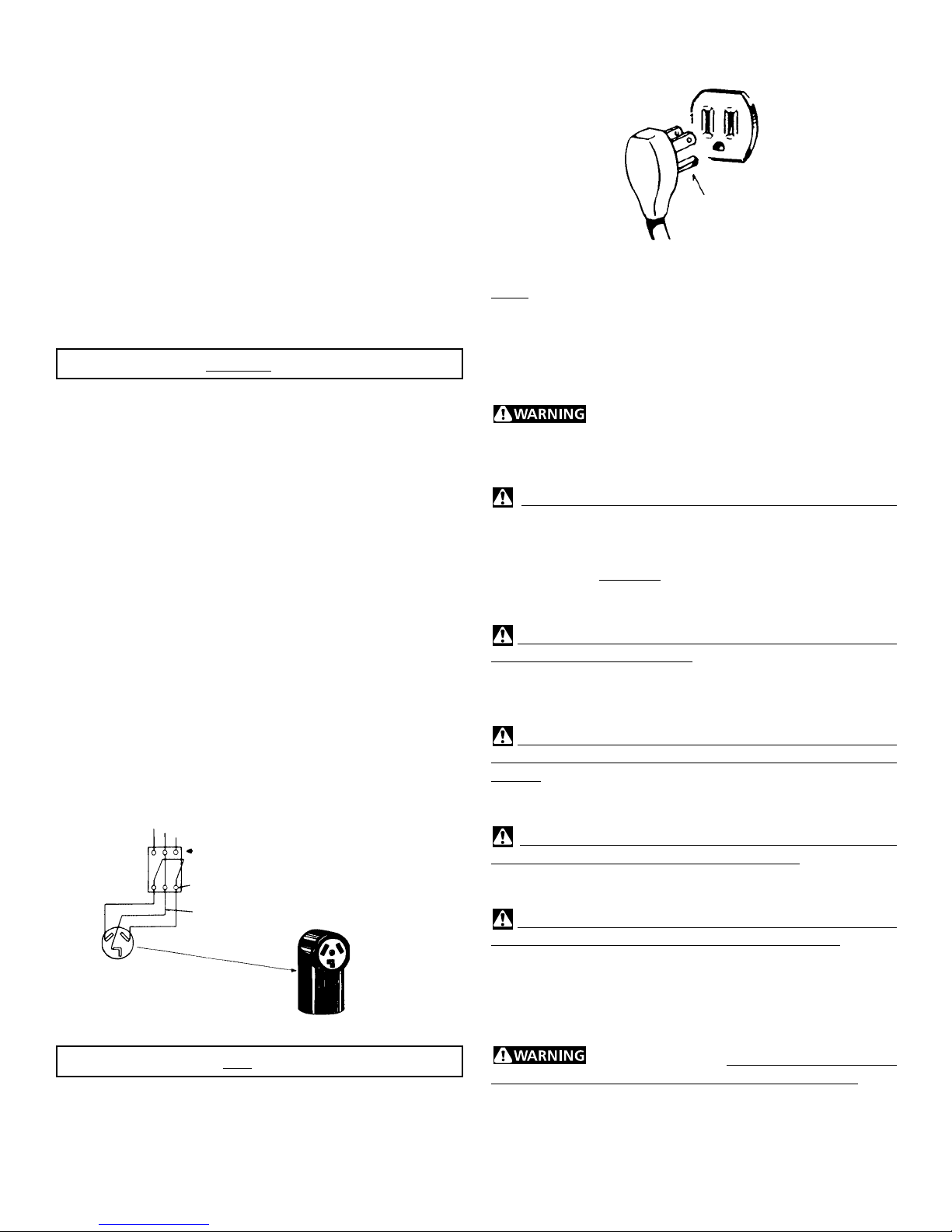
POWER SUPPLY
OUTLET
RECEPTACLE
(COPPER)
SUBJECT TO LOCAL REGULATIONS
CIRCUITCIRCUIT
CIRCUIT - Individual 15 amp. branch circuit fused with a 15
CIRCUITCIRCUIT
3 WIRE GROUNDED NEUTRAL
120-240 VOLT 60 CYCLE
MAIN FUSE BOX
30 AMP DELAYED ACTION
FUSES
OR CIRCUIT BREAKER
NEUTRAL WIRE
NEMA 10-30R (COPPER)
GASGAS
Dryer Dryer
GAS
Dryer
GASGAS
Dryer Dryer
amp. maximum time delay fuse or circuit breaker.
POWER SUPPLPOWER SUPPL
POWER SUPPL
POWER SUPPLPOWER SUPPL
YY
Y - 3 wire, 120 volt single phase, 60 Hz,
YY
Alternating Current.
POWER SUPPLPOWER SUPPL
POWER SUPPL
POWER SUPPLPOWER SUPPL
Y CORDY CORD
Y CORD - The dryer is equipped with a 120 volt
Y CORDY CORD
3-wire power cord.
NOTE: Do not underNOTE: Do not under
NOTE: Do not under
NOTE: Do not underNOTE: Do not under
any circumstancesany circumstances
any circumstances
any circumstancesany circumstances
remove groundingremove grounding
remove grounding
remove groundingremove grounding
prong from plug.prong from plug.
prong from plug.
prong from plug.prong from plug.
GROUNDING PRONGGROUNDING PRONG
GROUNDING PRONG
GROUNDING PRONGGROUNDING PRONG
EXHAUST SYSTEM REQUIREMENTSEXHAUST SYSTEM REQUIREMENTS
EXHAUST SYSTEM REQUIREMENTS
EXHAUST SYSTEM REQUIREMENTSEXHAUST SYSTEM REQUIREMENTS
Use only 4 inch (10.2 cm) diameter (minimum) rigid or flexible
metal duct and approved vent hood which has a swing-out
damper(s) that open when the dryer is in operation. When the
dryer stops, the dampers automatically close to prevent drafts
and the entrance of insects and rodents. T o avoid r estricting the
outlet, maintain a minimum of 12 inches (30.5 cm) clearance
between the vent hood and the ground or any other obstruction.
The following are specific requirements for The following are specific requirements for
The following are specific requirements for
The following are specific requirements for The following are specific requirements for
prpr
oper and safe operation of your droper and safe operation of your dr
pr
oper and safe operation of your dr
prpr
oper and safe operation of your droper and safe operation of your dr
these instructions can create excessive drying times andthese instructions can create excessive drying times and
these instructions can create excessive drying times and
these instructions can create excessive drying times andthese instructions can create excessive drying times and
fire hazards.fire hazards.
fire hazards.
fire hazards.fire hazards.
yeryer
yer
yeryer
. Failur. Failur
. Failur
. Failur. Failur
e to followe to follow
e to follow
e to followe to follow
Do not use plastic flexible duct to exhaust the dryer.
Excessive lint can build up inside exhaust system and create a
fire hazard and restrict air flow . Restricted air flow will incr ease
dryer times. If your present system is made up of plastic duct or
metal foil duct, replace it with a rigid or flexible metal duct.
Ensure the present duct is free of any lint prior to installingEnsure the present duct is free of any lint prior to installing
Ensure the present duct is free of any lint prior to installing
Ensure the present duct is free of any lint prior to installingEnsure the present duct is free of any lint prior to installing
dryer duct.dryer duct.
dryer duct.
dryer duct.dryer duct.
If the dryer is not exhausted outdoors, some fine lint will be
expelled into the laundry area. An accumulation of lint in any
area of the home can create a health and fire hazard.
dryer exhaust system MUST be exhausted to the outsidedryer exhaust system MUST be exhausted to the outside
dryer exhaust system MUST be exhausted to the outside
dryer exhaust system MUST be exhausted to the outsidedryer exhaust system MUST be exhausted to the outside
of the dwelling!of the dwelling!
of the dwelling!
of the dwelling!of the dwelling!
Do not allow combustible materials (for example: clothing,
draperies/curtains, paper) to come in contact with exhaust
system. The dryer
MUST NOTMUST NOT
MUST NOT be exhausted into a chimney, a
MUST NOTMUST NOT
wall, a ceiling, or any concealed space of a building which can
accumulate lint, resulting in a fire hazard.
Exceeding the length of duct pipe or number of elbows
allowed in the "
MAXIMUM LENGTH"MAXIMUM LENGTH"
MAXIMUM LENGTH" charts can cause an
MAXIMUM LENGTH"MAXIMUM LENGTH"
accumulation of lint in the exhaust system. Plugging the system
could create a fire hazard, as well as increase drying times.
Do not screen the exhaust ends of the vent system, nor use
any screws or rivets to assemble the exhaust system. Lint can
become caught in the screen, on the screws or rivets, clogging
the duct work and creating a fire hazard as well as increasing
drying times. Use an approved vent hood to terminate the duct
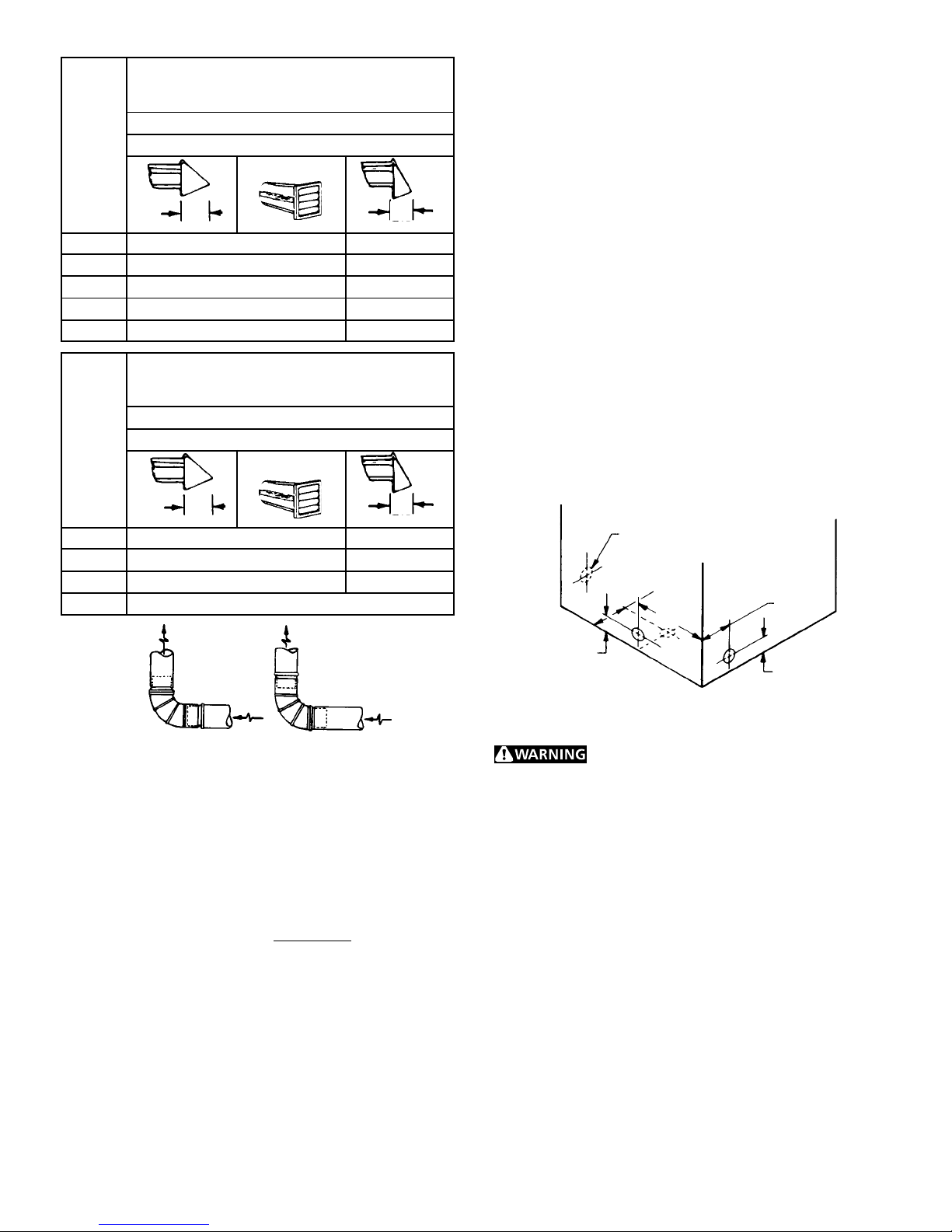
outdoors, and seal all joints with duct tape. All male duct pipe
fittings
MUSTMUST
MUST be installed downstream with the flow of air.
MUSTMUST
Explosion hazard.Explosion hazard.
Explosion hazard. Do not install the dryer
Explosion hazard.Explosion hazard.
where gasoline or other flammables are kept or stored. If the
dryer is installed in a garage, it must be a minimum of 18 inches
(45.7 cm) above the floor. Failure to do so can result in death,
explosion, fire or burns.
2
TheThe
The
TheThe
MAXIMUM LENGTH
of 4” (10.2 cm) Dia. Rigid Metal Duct
VENT HOOD TYPE
(Preferred)
Number
of
90°
Turns
0 60 ft. (18.28 m) 48 ft.(14.63 m)
1 52 ft. (15.84 m) 40 ft.(12.19 m)
2 44 ft. (13.41 m) 32 ft. (9.75 m)
3 32 ft . (9.75 m) 24 ft. (7.31 m)
4 28 ft. (8.53 m) 16 ft. (4.87 m)
4”
(10.2 cm)
Louvered
2½"
(6.35 cm)
MAXIMUM LENGTH
of 4” (10.2 cm) Dia. Flexible Metal Duct
VENT HOOD TYPE
(Preferred)
Number
of
90°
Turns
0 30 ft. (9.14 m) 18 ft. (5.49 m)
1 22 ft. (6.71 m) 14 ft. (4.27 m)
2 14 ft. (4.27 m) 10 ft. (3.05 m)
3 NOT RECOMMENDED
4”
(10.2 cm)
Louvered
2½"
(6.35 cm)
• Venting vertical through a roof may expose the exhaust
system to down drafts causing an increase in vent
restriction.
• Running the exhaust system through an uninsulated area
may cause condensation and faster accumulation of lint.
• Compression or crimping of the exhaust system will cause
an increase in vent restriction.
The exhaust system should be inspected and cleaned a
minimum of
every 18 months every 18 months
every 18 months with normal usage. The more
every 18 months every 18 months
the dryer is used, the more often you should check the
exhaust system and vent hood for proper operation.
EXHAUST DIRECTIONEXHAUST DIRECTION
EXHAUST DIRECTION
EXHAUST DIRECTIONEXHAUST DIRECTION
All dryers shipped from the factory are set up for rear exhausting.
However, on electric dryers, exhausting can be to the right or
left side of the cabinet or the bottom of the dryer . On gas dryers,
exhausting can be to the right side of the cabinet or the bottom
of the dryer. Directional exhausting can be accomplished by
installing Exhaust Kit, P/N 131456800, available through your
parts distributor . Follow the instructions supplied with the kit.
EXHAUST DUCT LOCAEXHAUST DUCT LOCA
EXHAUST DUCT LOCA
EXHAUST DUCT LOCAEXHAUST DUCT LOCA
SAME AS OTHER SIDESAME AS OTHER SIDE
SAME AS OTHER SIDE
SAME AS OTHER SIDESAME AS OTHER SIDE
5 7/8"5 7/8"
5 7/8"
5 7/8"5 7/8"
(15 cm)(15 cm)
(15 cm)
(15 cm)(15 cm)
13 1/2"13 1/2"
13 1/2"
13 1/2"13 1/2"
(34 cm)(34 cm)
(34 cm)
(34 cm)(34 cm)
TING DIMENSIONSTING DIMENSIONS
TING DIMENSIONS
TING DIMENSIONSTING DIMENSIONS
4 3/8"4 3/8"
4 3/8"
4 3/8"4 3/8"
(11 cm)(11 cm)
(11 cm)
(11 cm)(11 cm)
CORRECTCORRECT
CORRECT
CORRECTCORRECT
INSTALL MALE FITTINGS IN CORRECT DIRECTION
INCORRECTINCORRECT
INCORRECT
INCORRECTINCORRECT
In installations where the exhaust system is not described in the
charts, the following method must be used to determine if the
exhaust system is acceptable:
1. Connect an inclined or digital manometer between the
dryer and the point the exhaust connects to the dryer.
2. Set the dryer timer and temperature to air fluff (cool
down) and start the dryer .
3. Read the measurement on the manometer.
4. The system back pressure
MUST NOTMUST NOT
MUST NOT be higher than
MUST NOTMUST NOT
0.75 inches of water column. If the system back
pressure is less than 0.75 inches of water column, the
system is acceptable. If the manometer reading is
higher than 0.75 inches of water column, the system is
too restrictive and the installation is unacceptable.
Although vertical orientation of the exhaust system is
acceptable, certain extenuating circumstances could affect the
performance of the dryer:
• Only the rigid metal duct work should be used.
3 3/4"3 3/4"
3 3/4"
3 3/4"3 3/4"
(9.5 cm)(9.5 cm)
(9.5 cm)
(9.5 cm)(9.5 cm)
GAS SUPPLGAS SUPPL
GAS SUPPL
GAS SUPPLGAS SUPPL
Replace copper connecting pipe that is not Replace copper connecting pipe that is not
Replace copper connecting pipe that is not
Replace copper connecting pipe that is not Replace copper connecting pipe that is not
plastic-coated. Stainless steel or plastic-coated brass MUSTplastic-coated. Stainless steel or plastic-coated brass MUST
plastic-coated. Stainless steel or plastic-coated brass MUST
plastic-coated. Stainless steel or plastic-coated brass MUSTplastic-coated. Stainless steel or plastic-coated brass MUST
be used.be used.
be used.
be used.be used.
1. Installation
MUSTMUST
MUST conform with local codes, or in the absence
MUSTMUST
Y REQUIREMENTSY REQUIREMENTS
Y REQUIREMENTS
Y REQUIREMENTSY REQUIREMENTS
3 3/4"3 3/4"
3 3/4"
3 3/4"3 3/4"
(9.5 cm)(9.5 cm)
(9.5 cm)
(9.5 cm)(9.5 cm)
(9.5 cm)(9.5 cm)
(9.5 cm)
(9.5 cm)(9.5 cm)
of local codes, with the National Fuel Gas Code, ANSI Z223.1
(latest edition) or in Canada, the current CAN/CGA B149.
2. The gas supply line should be of 1/2 inch (1.27 cm) pipe.
3. If codes allow, flexible metal tubing may be used to connect
your dryer to the gas supply line. The tubing
MUSTMUST
MUST be
MUSTMUST
constructed of stainless steel or plastic-coated brass.
4. The gas supply line
MUST MUST
MUST have an individual shutoff valve.
MUST MUST
5. A 1/8 inch (0.32 cm) N.P.T . plugged tapping, accessible for
test gauge connection,
MUSTMUST
MUST be installed immediately
MUSTMUST
upstream of the gas supply connection to the dryer .
6. The dryer
MUSTMUST
MUST be disconnected from the gas supply piping
MUSTMUST
system during any pressure testing of the gas supply piping
system at test pressures in excess of 1/2 psig (3.45 kPa).
7. The dryer
MUSTMUST
MUST be isolated from the gas supply piping
MUSTMUST
system during any pressure testing of the gas supply piping
system at test pressures equal to or less than 1/2 psig (3.45
kPa).
3
 Loading...