

Installation
instructions
Instrucciones
paFa
Instalaci6n
Pre-lnstallation Requirements .................................... 2
Electrical Requirements ............................................ 2
Exhaust System Requirements ............................... 3-4
Gas Supply Requirements ........................................ 4
Location of Your Dryer........................................... 4-5
Rough-In Dimensions ............................................... 6
Mobile Home Installation ......................................... 7
Unpacking ............................................................ 7
Reversing Door Swing ........................................... 7-8
Electrical Installation ............................................... 9
Grounding Requirements ......................................... 9
Electrical Connections--3-wire ............................... 10
Electrical Connections--4-wire ............................... 10
Gas Connection ..................................................... 11
General Installation ................................................ 11
Replacement Parts................................................. 11
Requerimientos de instalaciOn preliminares............... 12
Requerimientos elOctricos....................................... 12
Requerimientos del sistema de escape.................. 12-13
Requerimientos del suministro de gas........................ 13
Ubicaci6n de su secadora....................................... 14
Dimensiones para la instalaciOn ............................... 15
InstalaciOn en casas mOviles.................................... 16
Desembalaje ........................................................ 16
Puerta reversible ............................................... 16-17
InstalaciOn el_ctrica ............................................... 18
Requerimientos para la puesta a tierra ...................... 18
ConexiOnes el_ctricas - trifilares ............................. 19
ConexiOnes elOctricas- tetrafilares .......................... 19
ConexiOn del gas.................................................. 20
General InstalaciOn................................................ 20
Piezas de recambio ................................................ 20
Before beginning installation, carefully read these instructions. This will simpfify the installation and ensure the dryer is installed
correctly and safely• Leave these instructions near the Dryer after installation for future reference.
NOTE: The electrical service to the Dryer must conform with local codes and ordinances and the latest edition of the National Electrical Code, ANSI/
NFPA70.
NOTE: The gas service to the Dryer must conform with local codes and ordinances and the latest edition of the National Fuel Gas Code ANSI
Z223.1.
NOTE: The Dryer is designed under ANSI Z 21.5.1 or ANSI/UL 2158 - CAN/CSA C22.2 (latest editions) for HOME USE only. This Dryer is not
recommended for commercial applications such as restaurants or beauty salons, etc.
Antes de comenzar la instalacion, lea cuidadosamente estas instrucciones. Esto simplificar4 la instalad6n y asegurar4 que /a secadora
se instale correctamente y de manera segura. Despu_s de completar la instaladon, coloque estas instrucciones cerca de la secadora
para referencia futura.
NOTA: La alimentaci6n electrica para la secadora debera cumplir coil los codigos y reglamentos locales y con la 01tima edicion del Codigo Electrico
Nacional, ANSI/NFPA 70.
NOTA: La alimentacion de gas para la secadora debera cumplir con los codigos y reglamentos locales y con la ultima edition del Codigo Nacional para
Gases Combustibles, ANSI Z223.1.
NOTA: La secadora esta clasificada para UBO DOMESTICO solamente, de acuerdo con la norma ANSI Z21.5.1 o ANSI/UL 2158 - CAN/CSA C22.2 (las
ultimas edici6nes). Esta secadora no se recomienda para uso commercial tal como en restaurantes, salones de belleza, etc.
_J__ Para su seguridad, siga las instrucciones contenidas en este manual a fin de reducir a un minimo los riesgos de incendio o
explosion o para evitar dat_os materiales, lesiones personales o la muerte.
No almacene ni utilice gasolina u otros vapores y Iiquidos inflamables en la proximidad de este o de cualquier otto artefacto electrico.
QUE DEBE HACER SI PERCIBE OLOR A GAS
• No trate de encender ning0n artefacto electrico.
• No toque ningun interruptor electrico; no use ningun telcfono en su edificio.
• Haga salir a todos los ocupantes de la habitaci6n, del edificio ydel lugar.
Llame a su proveedor de gas desde el telefono de un vecino. Siga las instrucciones del proveedor de gas.
Si no Iogra comunicarse con su proveedor de gas, Ilame al departamento de bomberos.
La instalaci6n y el servicio de mantenimiento debe de realizarlos un instalador calificado, la agencia de servicios o el proveedor de gas.
P/N 134528200A (0501)
For your safety the information in
this manual must be followed to minimize the
risk of fire or explosion or to prevent property
damage, personal injury or loss of life.
- Do not store or use gasoline or other
flammable vapors and liquid in the vicinity of
this or any other appliance.
- WHAT TO DO IF YOU SMELL GAS
. Do not try to light any appliance.
. Do not touch any electrical switch; do not
use any phone in your building.
. Clear the room, building or area of all
occupants.
. Immediately call your gas supplier from a
neighbor's phone. Follow the gas supplier's
instructions.
. If you cannot reach your gas supplier, call
the fire department.
POWER SUPPLY - 3 wire or 4-wire, 240 volt, single phase,
60 Hz,Alternating Current.
POWER SUPPLY CORD KIT - The dryer MUST employ a
3-conductor power supply cord NEMA 10-30 type SRDT
rated at 240 volt AC minimum, 30 amp., with 3 open end
spade lug connectors with upturned ends or closed loop
connectors OR a 4-conductor power supply cord NEMA
14-30 type SRDT or ST (as required) rated at 240 volt AC
minimum, 30 amp., with 4 open end spade lug connectors
with upturned ends or closed loop connectors and marked
for use with clothes dryers. If being installed in a
manufactured {mobile) home, the dryer MUST employ a
4-conductor power supply cord NEMA 14-30 type SRDTor
ST (as required) rated at 240 volt AC minimum, 30 amp.,
with 4 open end spade lug connectors with upturned ends
or closed loop connectors and marked for use with clothes
dryers. See ELECTRICAL CONNECTIONS for additional
instructions.
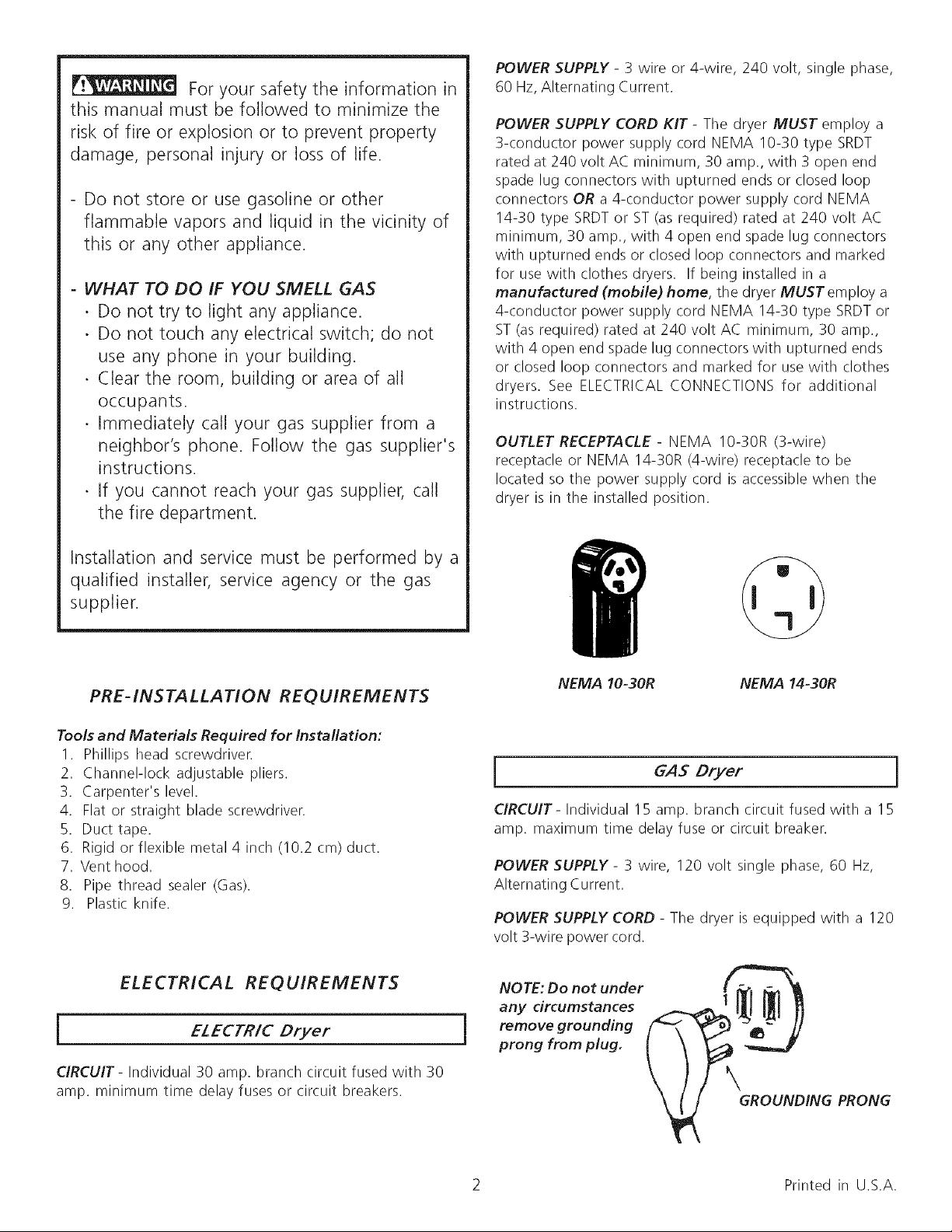
OUTLET RECEPTACLE - NEMA 10-30R (3-wire)
receptacle or NEMA 14-30R (4-wire) receptacle to be
located so the power supply cord is accessible when the
dryer is in the installed position.
Installation and service must be performed by a
qualified installer, service agency or the gas
supplier.
PRE-INSTALLATION REQUIREMENTS
Tools and Materials Required for Installation:
I. Phillips head screwdriver.
2. Channel-lock adjustable pliers.
3. Carpenter's level.
4. Flat or straight blade screwdriver.
5. Duct tape.
6. Rigid or flexible metal 4 inch (10.2 cm) duct.
7. Vent hood.
8. Pipe thread sealer (Gas).
9. Plastic knife.
ELECTRICAL REQUIREMENTS
j EZECTR/C Dryer
NEMA 10-30R NEMA 14-30R
GAS Dryer I
CIRCUIT- Individual 15 amp. branch circuit fused with a 15
amp. maximum time delay fuse or circuit breaker.
POWER SUPPLY - 3 wire, 120 volt single phase, 60 Hz,
Alternating Current.
POWER SUPPLY CORD - The dryer is equipped with a 120
volt 3-wire power cord.
NOTE: Do not under #._m _ •
any circumstances
prong from plug.
CIRCUIT- Individual 30 amp. branch circuit fused with 30
amp. minimum time delay fuses or circuit breakers.
j removegrounding
2 Printed in U.S.A.
GROUNDING PRONG

EXHAUST SYSTEM REQUIREMENTS
Use only 4 inch (10.2 cm) diameter (minimum) rigid or
flexible metal duct and approved vent hood which has a
swing-out damper(s) that open when the dryer is in
operation. When the dryer stops, the dampers automatically
close to prevent drafts and the entrance of insects and
rodents. To avoid restricting the outlet, maintain a minimum
of 12 inches (30.5 cm) clearance between the vent hood
and the ground or any other obstruction.
The following are specific requirements
for proper and safe operation of your dryer. Failure to
follow these instructions can create excessive drying
times and fire hazards.
Number
of
90°
Turns
0
I
2
3
4
MAXIMUM LENGTH
of 4" (10.2 cm) Dia. Rigid Metal Duct
VENT HOOD TYPE
(Preferred)
Louvered
(10.2 cm)
60ft. (18.28 m)
52ft. (15.84 m)
44ft. (13.41 m)
32ft (9.75 m)
28ft (8.53 m)
(6.35cm)
48 ft.(14.63 m)
40 ft.(12.19 m)
32 ft. (9.75 m)
24ft. (7.31 m)
16ft. (4.87 m)
Do not use plastic flexible duct to exhaust the dryer.
Excessive lint can build up inside exhaust system and
create a fire hazard and restrict air flow. Restricted air flow
will increase dryer times. If your present system is made up
of plastic duct or metal foil duct, replace it with a rigid or
flexible metal duct. Ensure the present duct is free of any
lint prior to installing dryer duct.
If the dryer is not exhausted outdoors, some fine
lint will be expelled into the laundry area. An
accumulation of lint in any area of the home can create a
health and fire hazard. The dryer exhaust system MUST
be exhausted to the outside of the dwelling!
Do not allow combustible materials (for example:
clothing, draperies/curtains, paper) to come in contact
with exhaust system. The dryer MUST NOT be exhausted
into a chimney, a wall, a ceiling, or any concealed space of
a building which can accumulate lint, resulting in a fire
hazard.
Exceeding the length of duct pipe or number of
elbows allowed in the "MAXIMUM LENGTH" charts can
cause an accumulation of lint in the exhaust system.
Plugging the system could create a fire hazard, as well as
increase drying times.
Do not screen the exhaust ends of the vent system,
nor use any screws or rivets to assemble the exhaust
system, Lint can become caught in the screen, on the
screws or rivets, clogging the duct work and creating a fire
hazard as well as increasing drying times. Use an approved
vent hood to terminate the duct outdoors, and seal all joints
with duct tape. All male duct pipe fittings MUST be installed
downstream with the flow of air.
Explosion hazard. Do not install the dryer
where gasoline or other flammables are kept or stored.
If the dryer is installed in a garage, it must be a minimum of
18 inches (45.7 cm) above the floor. Failure to do so can
result in death, explosion, fire or burns.
MAXIMUM LENGTH
of 4" (10.2 cm) Dia. Flexible Metal Duct
VENT HOOD TYPE
(Preferred)
Number
of
90°
Turns
(10.2 cm}
o
I
2
30ft. (9.14 m)
22ft. (6.71 m)
14ft. (4.27 m)
3
INSTALL MALE FITTINGS IN CORRECT DIRECTION
Louvered
_6.35cm)
18 ft. (5.49 m)
14ft (4.27 m)
lOft (3.05 m)
NOTRECOMMENDED
In installations where the exhaust system is not described
in the charts, the following method must be used to
determine if the exhaust system is acceptable:
1. Connect an inclined or digital manometer between the
dryer and the point the exhaust connects to the dryer.
2. Set the dryer timer and temperature to air fluff (cool
down) and start the dryer.
3. Read the measurement on the manometer.
4. The system back pressure MUST NOT be higher than
0.75 inches of water column. If the system back
pressure is lessthan 0.75 inches of water column, the
system is acceptable. If the manometer reading is
higher than 0.75 inches of water column, the system is
too restrictive and the installation is unacceptable.
Althoughverticalorientationoftheexhaustsystemis
acceptable,certainextenuatingcircumstancescouldaffect
theperformanceofthedryer:
• Only the rigid metal duct work should be used.
Venting vertical through a roof may expose the exhaust
system to down drafts causing an increase in vent
restriction.
Running the exhaust system through an uninsulated
area may cause condensation and faster accumulation
of lint.
Compression or crimping of the exhaust system will
cause an increase in vent restriction.
The exhaust system should be inspected and cleaned a
minimum of every 18months with normal usage. The more
the dryer is used, the more often you should check the
exhaust system and vent hood for proper operation.
EXHAUST DIRECTION
All dryers shipped from the factory are set up for rear
exhausting. However, on electric dryers, exhausting can be
to the right or left side of the cabinet or the bottom of the
dryer. On gas dryers, exhausting can be to the right side of
the cabinet or the bottom of the dryer. Directional
exhausting can be accomplished by installing Exhaust Kit,
P/N 131456800, available through your parts distributor.
Follow the instructions supplied with the kit.
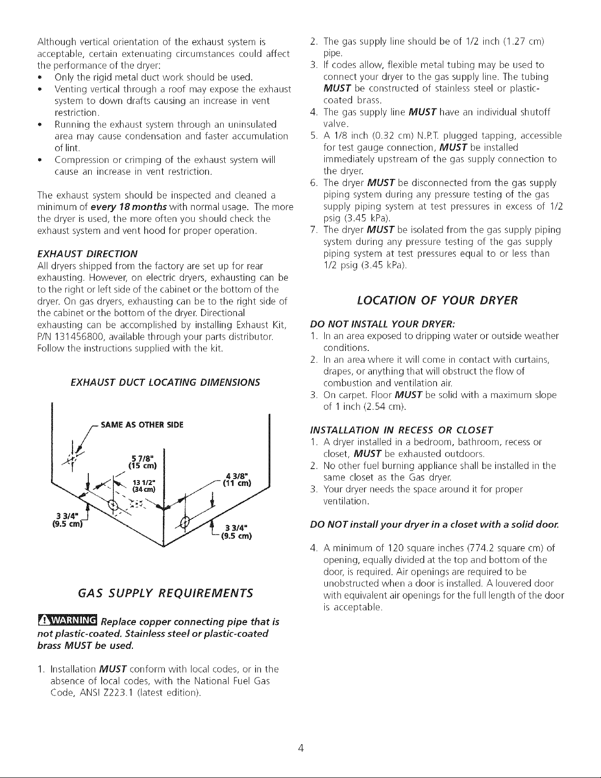
EXHAUST DUCT LOCATING DIMENSIONS
2. The gas supply line should be of I/2 inch (1.27 cm)
pipe.
3. If codes allow, flexible metal tubing may be used to
connect your dryer to the gas supply line. The tubing
MUST be constructed of stainless steel or plastic-
coated brass.
4. The gas supply line MUST have an individual shutoff
valve.
5. A I/8 inch (0.32 cm) N.RT. plugged tapping, accessible
for test gauge connection, MUST be installed
immediately upstream of the gas supply connection to
the dryer.
6. The dryer MUST be disconnected from the gas supply
piping system during any pressure testing of the gas
supply piping system at test pressures in excess of 1/2
psig (3.45 kPa).
7. The dryer MUST be isolated from the gas supply piping
system during any pressure testing of the gas supply
piping system at test pressures equal to or less than
I/2 psig (3.45 kPa).
LOCATION OF YOUR DRYER
DO NOT INSTALL YOUR DRYER:
I. In an area exposed to dripping water or outside weather
conditions.
2. In an area where it will come in contact with curtains,
drapes, or anything that will obstruct the flow of
combustion and ventilation air.
3. On carpet. Floor MUST be solid with a maximum slope
of 1 inch (2.54 cm).
S SAME AS OTHER SIDE
,33/4,"'_'_"c::-_j ".t_" -"*_';_(34¢nl).,...____3 3/4"(11¢!)
GAS SUPPLY REQUIREMENTS
Replace copper connecting pipe that is
not plastic-coated. Stainless steel or plastic-coated
brass MUST be used.
1. Installation MUST conform with local codes, or in the
absence of local codes, with the National Fuel Gas
Code, ANSI Z223.1 (latest edition).
INSTALLATION IN RECESS OR CLOSET
I. A dryer installed in a bedroom, bathroom, recess or
closet, MUST be exhausted outdoors.
2. No other fuel burning appliance shall be installed in the
same closet as the Gas dryer.
3. Your dryer needs the space around it for proper
ventilation.
DO NOT install your dryer in a closet with a solid door.
4. A minimum of 120 square inches (774.2 square cm) of
opening, equally divided at the top and bottom of the
door, is required. Air openings are required to be
unobstructed when a door is installed. A Iouvered door
with equivalent air openings for the full length of the door
is acceptable.
4

MINIMUM INSTALLATION CLEARANCES - Inches (cm)
SIDES REAR TOP FRONT
Alcove 0 (0 cm) 0 (0 cm) 15 (38.1 cm)
Closet 0(0cm) 0(0cm) 15(38.1cm) 1 (2.54cm)
Closet door ventilation required: 2 Iouvered openings each
60 square inches (387 square centimeters) -- 3 inches (7.6
cm) from bottom and top of door.
NOTE: Under counter and stack models-O inches(O cm)
for sides, rear, and top.
This dryer MUST be exhausted outdoors.
5. The following illustrations show minimum clearance
dimensions for proper operation in a recess or closet
installation.
II e"
_ll _ (0 cm)
II
60 sq. inches
(387.1 sq. cm)
60 sq. inches
(387.1 sq. cm)
CLOSET DOOR
Ii"___(38"1 cm)
II 1"
_11_ (2.54 cm)
........ol )
ii n
_,,_ 0 (0 cm)
1" (2.54 cm)
0"(0 cm)
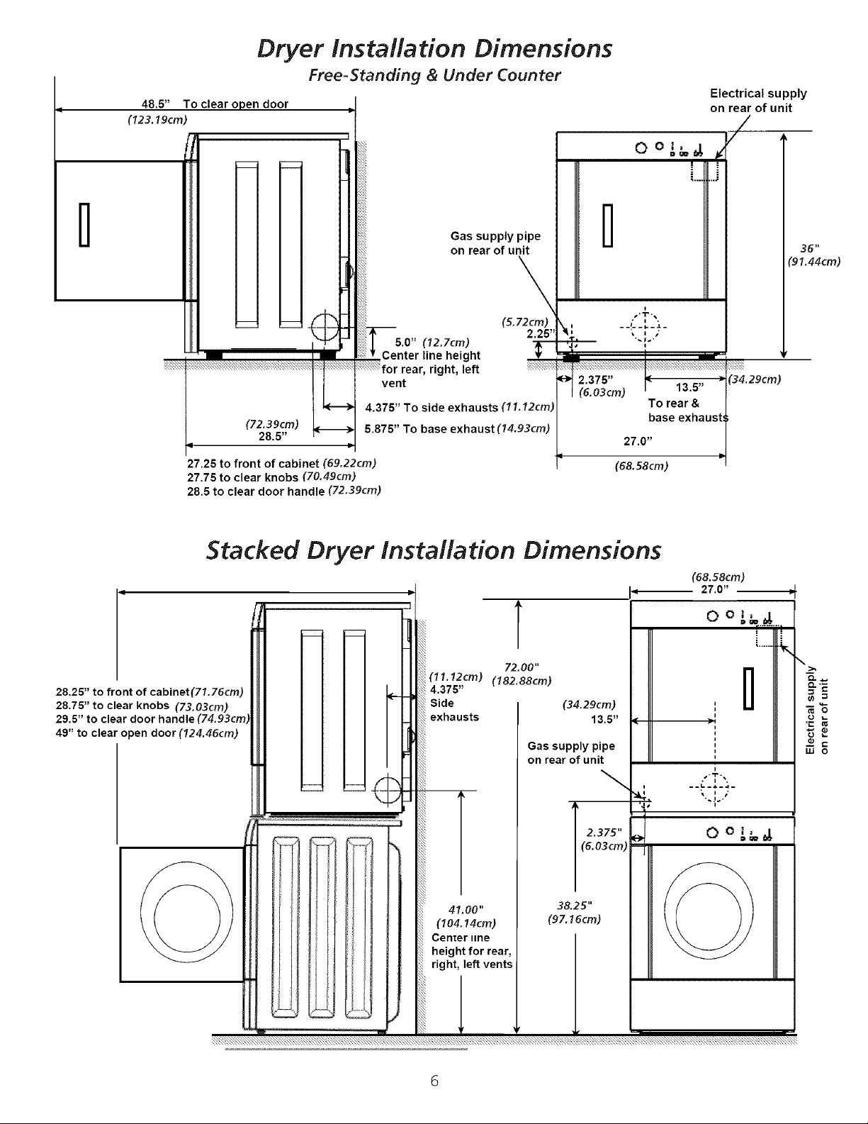
48.5" To clear open door
(123.19cm)
Dryer lnsta#ation Dimensions
Free=Standing & Under Counter
Electrical supply
on rear of unit
/
l
o o _,,_,_
i
....... J
l
__!: "__
27.0"
(68. 58cm)
I
,'T.,
To rear &
base exhaus
36"
(91.44cm)
(34.29cm)
(72.39cm)
28.5"
27.25 to front of cabinet (69.22cm)
27.75 to clear knobs (70.49cm)
28.5 to clear door handle (72.39cm)
Gas supply pipe
on rear of unit
\
(5.72cm)
5.0" (12.7cm)
Center line height
•,right, left
vent
4.375" To side exhausts (11.12cm)
5.875" To base exhaust (14.93cm)
2.25"
I--
Stacked Dryer insta#ation Dimensions
(68. 58cm)
i
27.0" -_
28.25" to front of cabinet(71.76cm)
28.75" to clear knobs (73.03cm)
29.5" to clear door handle
49" to clear open door (124.46cm)
T
72.00"
(11.12cm) (182.88cm)
4.375"
Side
exhausts
Gas supply pipe
on rear of unit
41.00"
(104.14cm)
Center line
height for rear,
right, left vents
o oL_
w o
I 2.375"
(6.03cm)
38.25"
(97.16cm)
G
MOBILE HOME INSTALLATION
UNPACKING
1. Dryer MUST be exhausted outside (outdoors, not beneath the
mobile home) using metal ducting that will not support
combustion. Metal ducting must be 4 inches (10.16 cm) in
diameter with no obstructions. Rigid metal duct is preferred.
2. If dryer is exhausted through the floor and area beneath the
mobile home is enclosed, the exhaust system MUST
terminate outside the enclosure with the termination securely
fastened to the mobile home structure.
3. When installing a gas dryer into a mobile home, a provision
must be made for outside make up air. This provision isto be
not lessthan twice the area of the dryer exhaust outlet.
4. This dryer MUST be fastened to the floor. Mobile Home
Installation Kit No. 346764 is available from your dealer.
5. Refer to pages 2 and 3 for other important venting
requirements.
6. Installation MUST conform to current Manufactured Home
Construction & Safety Standard (which is a Federal Regulation
Title 24 CFR-Part 32-80) or when such standard is not
applicable, with American National Standard for Mobile
Homes.
The dryer is designed under ANSI Z 21.5.1 or
ANSI/UL2158 - CAN/CSA C22.2 (latest editions) for HOME USE
only.
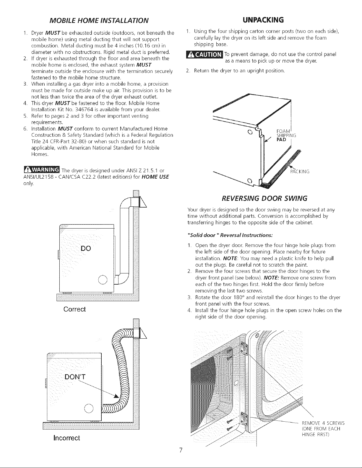
1. Using the four shipping carton corner posts (two on each side),
carefully lay the dryer on its left side and remove the foam
shipping base.
To prevent damage, do not use the control panel
as a means to pick up or move the dryer.
2. Return the dryer to an upright position.
FOAM
SHIPPING
_P_C KING
REVERSING DOOR SWING
Correct
DON'T
O
Your dryer is designed so the door swing may be reversed at any
time without additional parts. Conversion is accomplished by
transferring hinges to the opposite side of the cabinet.
"Solid door "Reversal Instructions:
1. Open the dryer door. Remove the four hinge hole plugs from
the left side of the door opening. Place nearby for future
installation. NOTE: You may need a plastic knife to help pull
out the plugs. Be careful not to scratch the paint.
2. Remove the four screws that secure the door hinges to the
dryer front panel (see below). NOTE: Remove one screw from
each of the two hinges first. Hold the door firmly before
removing the last two screws.
3. Rotate the door 180° and reinstall the door hinges to the dryer
front panel with the four screws.
4. Install the four hinge hole plugs in the open screw holes on the
right side of the door opening.
Incorrect
©
REMOVE 4 SCREWS
(ONE FROM EACH
HINGE FIRST)
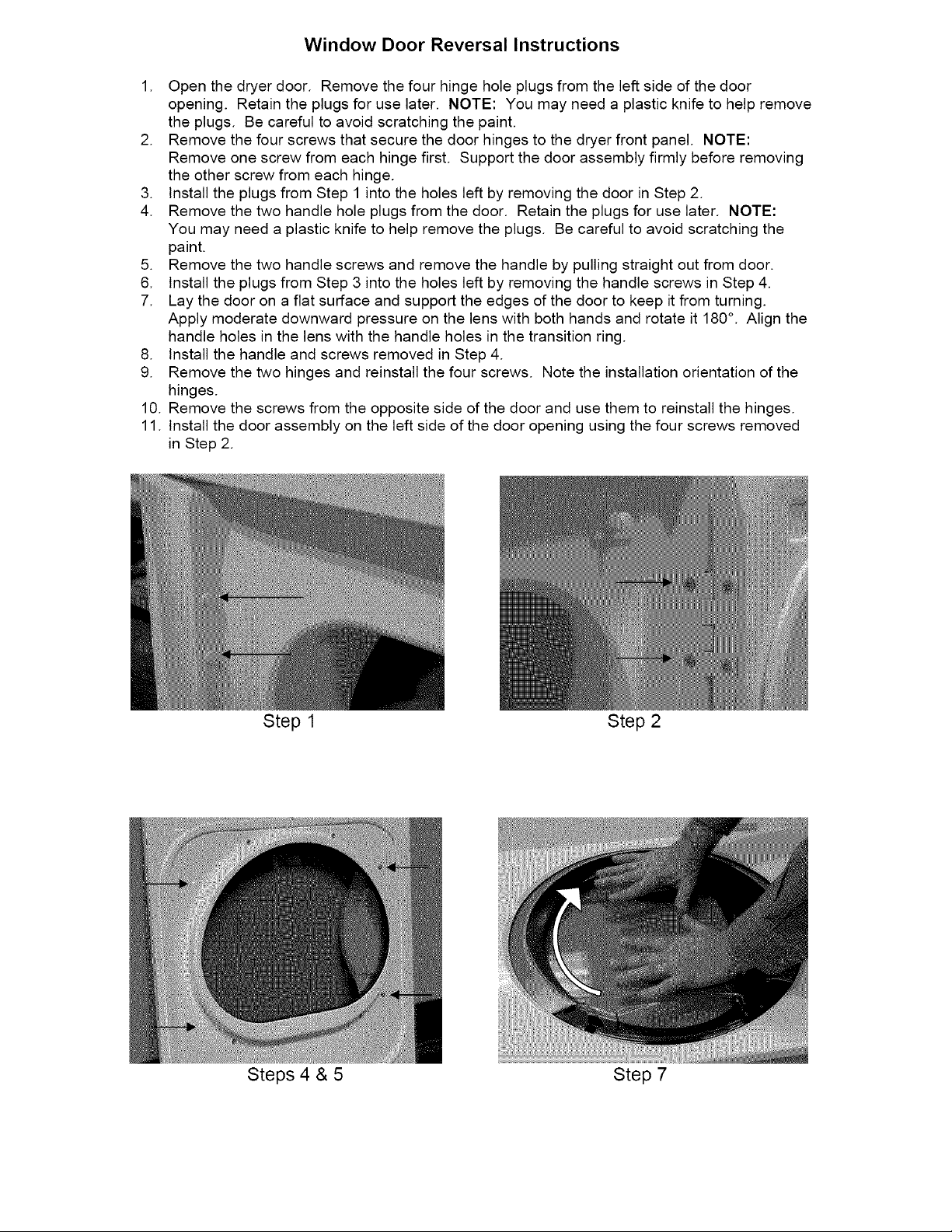
Window Door Reversal Instructions
1. Open the dryer door. Remove the four hinge hole plugs from the left side of the door
opening. Retain the plugs for use later. NOTE: You may need a plastic knife to help remove
the plugs. Be careful to avoid scratching the paint.
2. Remove the four screws that secure the door hinges to the dryer front panel. NOTE:
Remove one screw from each hinge first. Support the door assembly firmly before removing
the other screw from each hinge.
3. Install the plugs from Step 1 into the holes left by removing the door in Step 2.
4. Remove the two handle hole plugs from the door. Retain the plugs for use later. NOTE:
You may need a plastic knife to help remove the plugs. Be careful to avoid scratching the
paint.
5. Remove the two handle screws and remove the handle by pulling straight out from door.
6. Install the plugs from Step 3 into the holes left by removing the handle screws in Step 4.
7. Lay the door on a flat surface and support the edges of the door to keep it from turning.
Apply moderate downward pressure on the lens with both hands and rotate it 180°. Align the
handle holes in the lens with the handle holes in the transition ring.
8. Install the handle and screws removed in Step 4.
9. Remove the two hinges and reinstall the four screws. Note the installation orientation of the
hinges.
10. Remove the screws from the opposite side of the door and use them to reinstall the hinges.
11. Install the door assembly on the left side of the door opening using the four screws removed
in Step 2.
Step 1 Step 2
Steps 4 & 5 Step 7

ELECTRICAL INSTALLATION
i ELECTR/C Dryer i
The following are specific requirements
for proper and safe electrical installation of your dryer.
Failure to follow these instructions can create electrical
shock and/or a fire hazard.
This appliance MUST be properly grounded.
Electrical shock can result if the dryer is not properly
grounded. Follow the instructions in this manual for proper
grounding.
2. If your dryer isequipped with a power supply cord having
an equipment-grounding conductor and a grounding plug,
the plug MUST be plugged into an appropriate, copper
wired receptacle that is properly installed and grounded
in accordance with all local codes and ordinances. If in
doubt, call a licensed electrician.
For a permanently connected dryer:
I. The dryer MUST be connected to a grounded metal,
permanent wiring system; or an equipment grounding
conductor must be run with the circuit conductors and
connected to the equipment-grounding terminal or lead
on the appliance.
Do not use an extension cord with this dryer. Some
extension cords are not designed to withstand the amounts
of electrical current this dryer utilizes and can melt, creating
electrical shock and/or fire hazard. Locate the dryer within
reach of the receptacle for the length power cord to be
purchased, allowing some slack in the cord. Refer to the
pre-installation requirements in this manual for the proper
power cord to be purchased.
A U.L. approved strain relief must be installed onto
powercord. If the strain relief is not attached, the cord can
be pulled out of the dryer and can be cut by any movement
of the cord, resulting in electrical shock.
Do not use an aluminum wired receptacle with a
copper wired power cord and plug (or vice versa). A
chemical reaction occurs between copper and aluminum
and can cause electrical shorts. The proper wiring and
receptacle is a copper wired power cord with a copper
wired receptacle.
NOTE: Dryers operating on 208 volt power supply will have
longer drying times than operating on 240 volt power supply.
GAS Dryer I
This dryer is equipped with athree-prong (grounding) plug
for your protection against shock hazard and should be
plugged directly into a properly grounded three-prong
receptacle. Do not cut or remove the grounding prong from
this plug.
GROUNDING REQUIREMENTS
i ELECTR/C Dryer i
Improper connection of the equipment
grounding conductor can result in a risk of electrical shock.
Check with a licensed electrician if you are in doubt asto
whether the appliance is properly grounded.
For a grounded, cord-connected dryer:
I. The dryer MUSTbe grounded. In the event of a
malfunction or breakdown, grounding will reduce the risk
of electrical shock by a path of least resistance for
electrical current.
GREEN GREEN POWER CORD
GRO GREEN GROUND WIRE SILVERTERMINAL
SC REW SILVERTERMINAL SC REW TERMINAL BLOCK
NEUTRAL
GROUND
WIRE
_UT
TIGHTEN NUT
TO THESE
THREADS
STRAIN
RELIEF
MOUNTINE
BRACKET POWER CORD
GROUND
GROUND
WIRE
RE[)"
STRAIN \
RELIEF \_,
MOUNTING_
BRAC KET_
• POWER
CORD
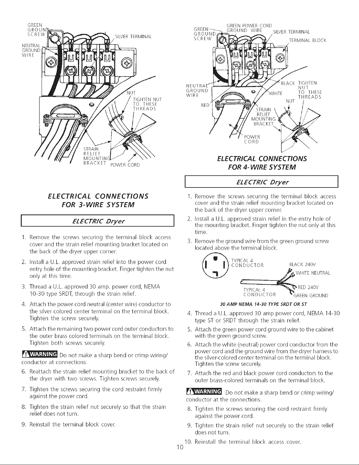
ELECTRICAL CONNECTIONS
FOR 4- WiRE SYSTEM
_VHITE
TIGHTEN
NUT
TO THESE
THREADS
N,UT /
II'
ELECTRICAL CONNECTIONS
FOR 3-WIRE SYSTEM
I ELECTR/C Dryer 1
1. Remove the screws securing the terminal block access
cover and the strain relief mounting bracket located on
the back of the dryer upper corner.
2. Install a U.L approved strain relief into the power cord
entry hole of the mounting bracket. Finger tighten the nut
only at this time.
3. Thread a U.L approved 30 amp. power cord, NEMA
10-30 type SRDT,through the strain relief.
4. Attach the power cord neutral (center wire) conductor to
the silver colored center terminal on the terminal block.
Tighten the screw securely.
5. Attach the remaining two power cord outer conductors to
the outer brass colored terminals on the terminal block.
Tighten both screws securely.
Do not make a sharp bend or crimp wiring/
conductor at connections.
6. Reattach the strain relief mounting bracket to the back of
the dryer with two screws. Tighten screws securely.
7. Tighten the screws securing the cord restraint firmly
against the power cord.
8. Tighten the strain relief nut securely so that the strain
relief does not turn.
g. Reinstall tile terminal block cover.
i
I.
Remove the screws securing the terminal block access
ELECTR/C Dryer ]
cover and the strain relief mounting bracket located on
the back of the dryer upper cornen
.
Install a U.L approved strain relief in the entry hole of
the mounting bracket. Finger tighten the nut only at this
time.
.
Remove the ground wire from the green ground screw
located above the terminal block.
CONDUCTOR BLACK 240V
TYPICAL 4
WHITE NEUTRAL
TYPICAL 4 -'%_
CONDUCTOR _'GREEN GROUND
30 AMP NEMA 14-30 TYPE SRDT OR ST
RED 240V
4. Thread a U.L approved 30 amp power cord, NEMA 14-30
type ST or SRDTthrough the strain relief.
5. Attach the green power cord ground wire to the cabinet
with the green ground screw.
6. Attach the white (neutral) power cord conductor from the
power cord and the ground wire from the dryer harness to
the silver-colored center terminal on the terminal block.
Tighten the screw securely.
7. Attach the red and black power cord conductors to the
outer brass-colored terminals on the terminal block.
Do not make a sharp bend or crimp wiring/
conductor at the connections.
8. Tighten the screws securing the cord restraint firmly
against the power cord.
9. Tighten the strain relief nut securely so the strain relief
does not turn.
10. Reinstall the terminal block access cover.
10
GAS CONNECTION
1. Remove the shipping cap from gas pipe at the rear of
the dryer.
NOTE: DO NOT connect the dryer to L.R gas service
without converting the gas valve. An L.R
conversion kit must be installed by a qualified gas
technician.
.
Connect a I/2 inch (1.27 cm) I.D. semi-rigid or approved
pipe from gas supply line to the 3/8 inch (0.96 cm) pipe
located on the back of the dryer (see pages 6 and 7).
Use a I/2 inch to 3/8 inch (1.27 cm to 0.96 cm) reducer
for a connection. Apply an approved thread sealer that
is resistant to the corrosive action of liquefied gases on
all pipe connections.
.
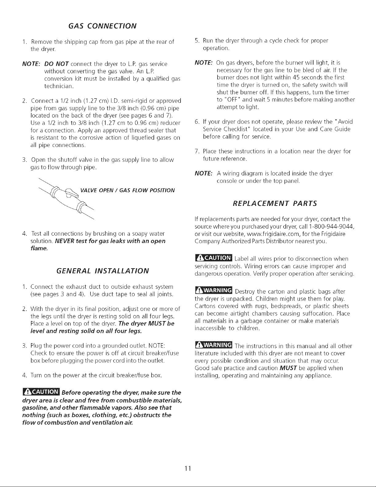
Open the shutoff valve in the gas supply line to allow
gasto flow through pipe.
OPEN / GAS FLOW POSITION
5. Run the dryer through a cycle check for proper
operation.
NOTE: On gas dryers, before the burner will light, it is
necessary for the gas line to be bled of air. If the
burner does not light within 45 seconds the first
time the dryer is turned on, the safety switch will
shut the burner off. If this happens, turn the timer
to "OFF" and wait 5 minutes before making another
attempt to light.
6. If your dryer does not operate, please review the "Avoid
Service Checklist" located in your Use and Care Guide
before calling for service.
7. Placethese instructions in a location near the dryer for
future reference.
NOTE: A wiring diagram is located inside the dryer
console or under the top panel.
REPLA CEMENT PARTS
4. Test all connections by brushing on a soapy water
solution. NEVER test for gas leaks with an open
flame.
GENERAL INSTALLATION
1. Connect the exhaust duct to outside exhaust system
(see pages3 and 4). Use duct tape to seal all joints.
2. With the dryer in its final position, adjust one or more of
the legs until the dryer is resting solid on all four legs.
Placea level on top of the dryer. The dryer MUSTbe
level and resting solid on all four legs.
3. Plug the power cord into a grounded outlet. NOTE:
Check to ensure the power is off at circuit breaker/fuse
box before plugging the power cord into the outlet.
4. Turn on the power at the circuit breaker/fuse box.
Before operating the dryer, make sure the
dryer area is clear and free from combustible materials,
gasoline, and other flammable vapors. Also see that
nothing (such as boxes, clothing, etc.) obstructs the
flow of combustion and ventilation air.
If replacements parts are needed for your dryer, contact the
source where you purchased your dryer, call 1-800-944-9044,
or visit our website, www.frigidaire.com, for the Frigidaire
Company Authorized Parts Distributor nearest you.
Label all wires prior to disconnection when
servicing controls. Wiring errors can cause improper and
dangerous operation. Verify proper operation after servicing.
Destroy the carton and plastic bags after
the dryer is unpacked. Children might use them for play.
Cartons covered with rugs, bedspreads, or plastic sheets
can become airtight chambers causing suffocation. Place
all materials in a garbage container or make materials
inaccessible to children.
The instructions in this manual and all other
literature included with this dryer are not meant to cover
every possible condition and situation that may occur.
Good safe practice and caution MUST be applied when
installing, operating and maintaining any appliance.
11
 Loading...