

Frigidaire GLEB27M9FB, PLEB27M9EC, GLEB30M9FS Installation Instructions Manual
MICROWAVE/ WALL OVEN COMBINATION
B
A
D
F
I
H
G
11½”
(29.2 cm)
11½”
(29.2 cm)
1¼”
(3.2 cm)
Min.
1¼”
(3.2 cm)
Min.
3” (7.6 cm)
Max.
3” (7.6 cm)
Max.
1” (2.5 cm)
Min.
1” (2.5 cm)
Min.
40-15/16”
(104 cm)
40-15/16”
(104 cm)
C
INSTALLATION INSTRUCTIONS
INSTALLATION AND SERVICE MUST BE PERFORMED BY A QUALIFIED INSTALLER.
IMPORTANT: SAVE FOR LOCAL ELECTRICAL INSPECTOR'S USE.
READ AND SAVE THESE INSTRUCTIONS FOR FUTURE REFERENCE.
FOR YOUR SAFETY: Do not store or use gasoline or other flammable vapors and liquids in
the vicinity of this or any other appliance.
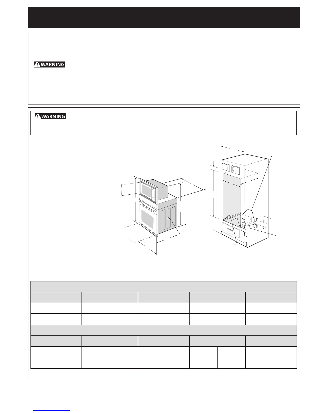
Your new wall oven has been designed to fit a limited variety of cutout sizes to make the job of installing
easier. The first step of your installation should be to measure your current cutout dimensions and
compare them to the cutout dimensions chart below for your model. You may find little or no cabinet
work is necessary.
Do not remove spacers (if equipped) on the side walls and/or on the back of the built-in
oven. These spacers center the oven in the space provided. The oven must be centered to prevent
excess heat buildup that may result in heat damage or fire.
NOTES:
1. Base must be capable of supporting 225 pounds (102 kg).
2. Allow at least 21" (53.3 cm) clearance in front of oven for door
depth when it is open.
3. Dimension G (cutout depth) is
critical to the proper installation of
the built-in oven. If the oven
decorative trim does not butt
against the cabinet verify
dimension G to assure it is the
required depth.
Door Open
(see note 2)
* Suggested distance from floor
is 11½" (29.2 cm).
Minimum required distance is 4
Figure 1
½" (11.4 cm)
PRODUCT DIMENSIONS
Spacer
2" (5 cm) Wide Wood
Spacer if Needed
Hole for
Cable
(right or
left side
depending
on model)
Electrical
Junction Box
(right or left side)
MODEL
27" (68.6 cm) Wall Oven
30" (76.2 cm) Wall Oven
27" (68.6 cm) Wall Oven
30" (76.2 cm) Wall Oven
MODEL
24
28½ (72.4)
All dimensions are stated in inches and (cm).
Printed in United States
27 (68.6)
30 (76.2)
Min. F Max.
7
/8 (63.2)
A
B
42¾ (108.6)
42¾ (108.6)
CUTOUT DIMENSIONS AND CABINET WIDTH
29 (73.7)
G (Min.)
23½ (59.7)
23½ (59.7)
1
Min. H Max.
1
41
/8 (104.5)
1
41
/8 (104.5)
25¼ (64.1)
C
245/8 (62.5)
28¼ (71.8)
41¼ (104.8)
41¼ (104.8)
D
24½ (62.2)
24½ (62.2)
I
271/8 (68.9) Min
1
/8 (76.5) Min
30
P/N 318201521 (0503) Rev. A
English – pages 1-6
Español – páginas 7-12
MICROWAVE/ WALL OVEN COMBINATION
INSTALLATION INSTRUCTIONS
Important Notes to the Installer
1. Read all instructions contained in these installation
instructions before installing the combination oven.
2. Remove all packing material from the oven
compartments before connecting the electrical supply
to the wall oven.
3. Observe all governing codes and ordinances.
4. Be sure to leave these instructions with the consumer.
5. Oven door may be removed to facilitate installation.
6. THIS COMBINATION OVEN IS NOT APPROVED FOR
STACKABLE OR SIDE-BY-SIDE INSTALLATION.
Important Note to the Consumer
Keep these instructions with your Owner's Guide for future
reference. Do not discard oven removal tools found in the
literature bag.
IMPORTANT SAFETY INSTRUCTIONS
• Be sure your combination oven is installed and
grounded properly by a qualified installer or
service technician.
• This wall oven must be electrically grounded in
accordance with local codes or, in their absence,
with the National Electrical Code ANSI/NFPA
No.70- latest edition in United Sates, or with CSA
Standard C22.1, Canadian Electrical Code, Part 1, in
Canada.
Stepping, leaning or sitting on the
door of this wall oven can result in serious injuries
and can also cause damage to the wall oven.
1. Carpentry
Refer to figure 1 for the dimensions applicable to your
appliance, and the space necessary to receive the
combination oven. The oven support surface may be
solid plywood or similar material, however the surface
must be leveled from side to side and from front to rear.
2. Electrical Requirements
This combination oven must be supplied with the proper
voltage and frequency, and connected to an individual,
properly grounded branch circuit, protected by a circuit
breaker or fuse, having amperage as noted on the rating
plate (the rating plate is located on the side trim).
Observe all governing codes and local ordinances
1. A 3-wire or 4-wire single phase 120/240 or 120/208
Volt, 60 Hz AC only electrical supply is required on
a separate circuit fused on both sides of the line
(time-delay fuse or circuit breaker is recommended).
DO NOT fuse neutral. The fuse size must not exceed
the circuit rating of the appliance specified on the
nameplate.
2. The combination oven can consume up to 5200W
when both ovens are operating. Use a circuit
breaker of 30 Amp with wire gauge #10 AWG.
NOTE: Wire sizes and connections must conform with
the fuse size and rating of the appliance in accordance
with the American National Electrical Code ANSI/NFPA
No. 70-latest edition, or with Canadian CSA Standard
C22.1, Canadian Electrical Code, Part 1, and local codes
and ordinances.
• Never use your wall oven for warming or heating
the room. Prolonged use of the wall oven without
adequate ventilation can be dangerous.
The electrical power to the oven must
be shut off while line connections are being made.
Failure to do so could result in serious injury or
death.
An extension cord should not be used
with this appliance. Such use may result in a fire,
electrical shock, or other personal injury.
3. This combination oven should be connected to the
fused disconnect (or circuit breaker) box through
flexible armored or nonmetallic sheathed cable. The
flexible armored cable extending from the appliance
should be connected directly to the junction box. The
junction box should be located as shown in Figure 1
and with as much slack as possible remaining in the
cable between the box and the appliance, so the
latter can be moved if servicing is ever necessary.
4. A suitable strain relief must be provided to attach
the flexible armored cable to the junction box.
2
MICROWAVE/ WALL OVEN COMBINATION
INSTALLATION INSTRUCTIONS
Electrical Shock Hazard
• Electrical ground is required on this appliance.
• Do not connect to the electrical supply until
appliance is permanently grounded.
• Disconnect power to the junction box before
making the electrical connection.
• This appliance must be connected to a
grounded, metallic, permanent wiring system,
or a grounding connector should be connected
to the grounding terminal or wire lead on the
appliance.
• Do not use a gas supply line for grounding the
appliance.
Failure to do any of the above could result in a
fire, personal injury or electrical shock.
In cold weather shipping and storage
conditions, make sure that oven is in final location at
least three (3) hours before switching on power.
Switching on power while oven is still cold may damage
the oven controls.
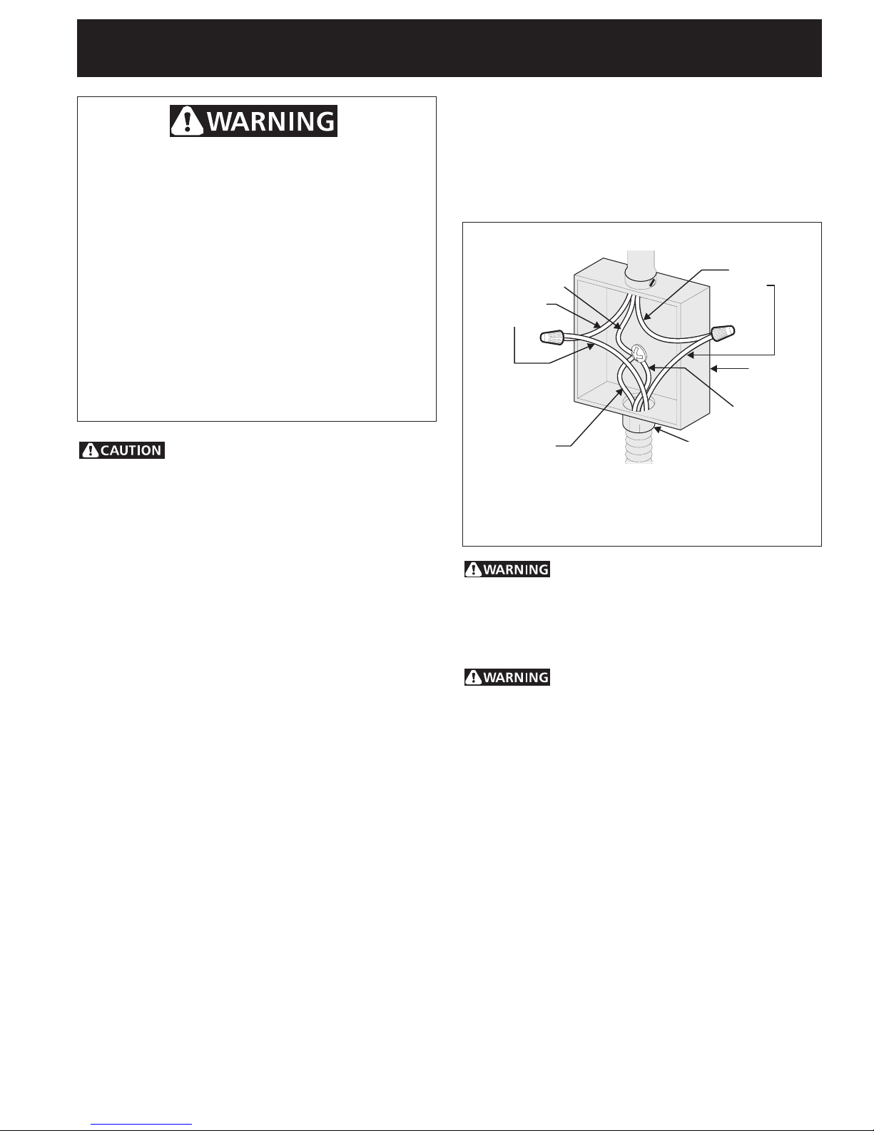
Where local codes permit connecting the appliancegrounding conductor to the neutral (white) wire
(see figure 2):
1. Disconnect the power supply.
2. In the circuit breaker, fuse box or junction box:
connect appliance and power supply cable wires as
shown in Figure 2.
Cable from Power Supply
White Wire
(Neutral)
Red
Wires
Ground Wire
(Bare or Green Wire)
Cable from appliance
3-WIRE GROUNDED JUNCTION BOX
U.L.-Listed Conduit
Connector (or CSA listed)
Figure 2
Black
Wires
Junction
Box
White Wire
(Neutral)
3. Electrical connection
It is the responsibility and obligation of the consumer to
contact a qualified installer to assure that the electrical
installation is adequate and is in conformance with the
National Electrical Code ANSI/NFPA No. 70-latest
edition, or with CSA Standard C22.1, Canadian
Electrical Code, Part 1, and local codes and ordinances.
Electrical ground is required on this appliance.
This appliance is equipped with a copper conductor
flexible cable. If connection is made to aluminum house
wiring, use only special connectors which are approved
for joining copper and aluminum wires in accordance
with National Electrical Code and local codes and
ordinances.
This appliance is manufactured with a white neutral
power supply wire and a frame connected green or bare
copper grounding wire.
Improper connection of aluminum
house wiring to copper leads can result in a short
circuit or fire. Use only connectors designed for
joining copper to aluminum, and follow the
manufacturer's recommended procedure closely.
You may not ground the oven
through the neutral (white) wire if oven is used in
a new branch circuit installation (1996 NEC), mobile
home, recreational vehicle, or where local codes do
not permit grounding through the neutral (white)
wire. When grounding through the neutral (white)
wire is prohibited, you must use a 4-wire power
supply cable. See Figure 3. Failure to heed this
warning may result in electrocution or other
serious personal injury.
3
MICROWAVE/ WALL OVEN COMBINATION
INSTALLATION INSTRUCTIONS
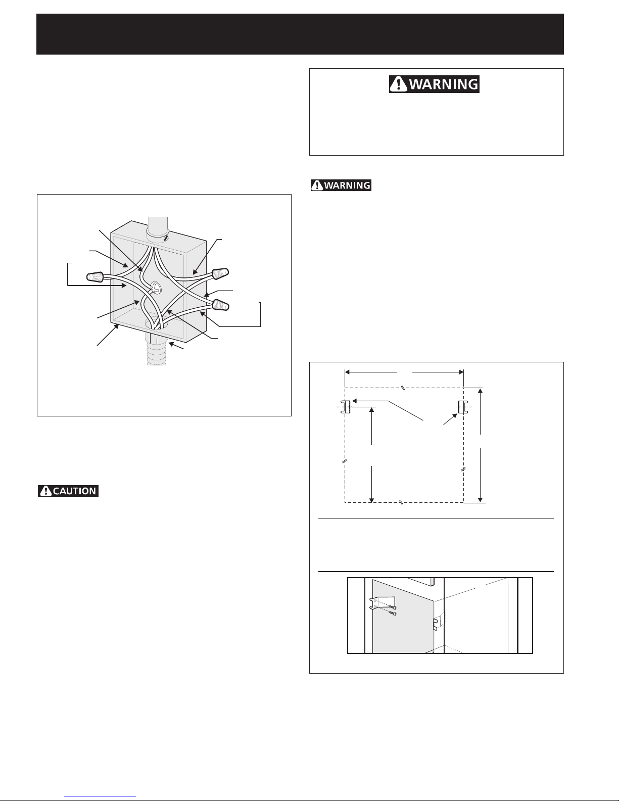
If oven is used in a new branch circuit installation
(1996 NEC), mobile home, recreational vehicle, or
where local codes DO NOT permit grounding
through the neutral (white) wire (see figure 3):
1. Disconnect the power supply.
2. Separate the green (or bare copper) and white
appliance cable wires.
3. In the circuit breaker, fuse box or junction box:
connect appliance and power supply cable wires as
shown in Figure 3.
Cable from Power Supply
Ground Wire
White Wire
Red
Wires
Black
Ground Wire
(Bare or Green
Wire)
Junction Box
4-WIRE GROUNDED JUNCTION BOX
U.L.-Listed Conduit
Connector (or CSA listed)
Cable from appliance
Figure 3
Wires
White Wire
Heavy Weight Hazard
• Use 2 or more people to move and install this
combination oven.
• Failure to follow this instruction can result in injury
or damage to the unit.
4. Cabinet Installation
The combination oven can tip when
the door is open. The mounting brackets supplied
with the oven must be attached to the cabinet and
the appliance to prevent tipping of the wall oven
and injury to persons.
Mounting Brackets Installation Instructions
1. Unpack the wall oven. Remove the bottom trim taped
on the oven side panel. Find the 2 mounting brackets
and screws included in the literature package.
2. Install the mounting bracket in the wall cabinet as
shown in Figure 4. Note: To prevent damage to cabinet,
it is recommended to drill 1/16" (0.16 cm) dia. pilot
holes before installing the mounting brackets.
F
DO NOT ground to a gas supply pipe. DO NOT connect
to electrical power supply until appliance is permanently
grounded. Connect the ground wire before turning on
the power (Figure 3).
If connecting to a 4-wire electrical
system (mobile homes), the appliance frame MUST
NOT be connected to the neutral wire of the 4-wire
electrical system.
NOTE TO ELECTRICIAN: The armored cable leads
supplied with the appliance are UL-recognized for
connection to larger gauge household wiring. The
insulation of the leads is rated at temperatures much
higher than temperature rating of household wiring. The
current carrying capacity of the conductor is governed by
the temperature rating of the insulation around the wire,
rather than the wire gauge alone.
Mounting
Brackets
22 3/16" *
(56.4 cm)
H
* If wood spacers are needded (see figure1 ) please
calculate this dimension from the top of the spacer to
the middle of the mounting bracket.
Figure 4
3.Insert the oven into the cabinet opening. Slide oven
inward leaving 1½" (3.8 cm) clearance between the
oven and front of cabinet (see Figure 5). Pull the armored
cable through the hole for it in the cabinet and toward
the junction box while moving the appliance inward.
4
 Loading...