

Frigidaire GLDB957JB, ADW750EA, GLDB958JB, ADW850EA, GPDB998JC Service Manual

SERVICE MANUAL
24" BUILT-IN DISHWASHERS
ELECTRONIC CONTROL
PRECISION WASH SYSTEM
5995293536

TABLE OF CONTENTS
SAFE SERVICING PRACTICES ...................................................................................... 3
WHAT'S NEW ................................................................................................................... 4
MODEL TECHNICAL SPECIFICATIONS......................................................................... 5
Model Diagram Index ...................................................................................................................................... 5
Electrical ........................................................................................................................................................ 5
Water Supply ................................................................................................................................................. 5
Component Resistance (Ohms) ....................................................................................................................... 5
Temp Assure and Heat Delay Operation ...................................................................................................... 6
CONSTRUCTION AND OPERATION
Water Distribution System ............................................................................................................................ 7
Wash Pump ........................................................................................................................................... 7
Different Types of Precision Wash Motors ............................................................................................. 8
Upper Spray Arm ................................................................................................................................... 9
Lower Spray Arm ................................................................................................................................... 9
Filter ....................................................................................................................................................... 9
Drain Pump ............................................................................................................................................ 9
Drying System .............................................................................................................................................. 10
Lower Vent Housing ............................................................................................................................... 10
Vent Valve.............................................................................................................................................. 10
Vent Actuator ......................................................................................................................................... 10
Blower .................................................................................................................................................... 10
Upper Vent Housing ............................................................................................................................... 10
Dispensing System ....................................................................................................................................... 11
Detergent & Rinse Aid Dispenser ........................................................................................................... 11
Door Latch Assembly ................................................................................................................................... 11
Electronic Control and Thermistor ................................................................................................................ 11
No Heat Dry ........................................................................................................................................... 12
Temp Assure.......................................................................................................................................... 12
Heat Delay ............................................................................................................................................. 12
High Limit Thermostat .................................................................................................................................. 12
Dishwasher Leveling System........................................................................................................................ 12
Temperature Controls With Thermister......................................................................................................... 13
Cycles .................................................................................................................................................... 13
Options .................................................................................................................................................. 13
Dirt Sensor ................................................................................................................................................... 13
Rinse Aid Dispenser ..................................................................................................................................... 14
Bottom View ................................................................................................................................................. 15
DISASSEMBLY
Safety Precautions ....................................................................................................................................... 16
Control Panel ................................................................................................................................................ 16
Electronic Keypad - Slimline & Regular ........................................................................................................ 16
Electronic Keypad - Selectronic .................................................................................................................... 16
Control Board ............................................................................................................................................... 16
Door Panel ................................................................................................................................................... 16
Door Vent Assembly ..................................................................................................................................... 16
Vent Valve .................................................................................................................................................... 17
Page 1

TABLE OF CONTENTS
Vent Blower .................................................................................................................................................. 17
Door Latch Assembly ................................................................................................................................... 17
Detergent / Rinse Aid Dispenser .................................................................................................................. 17
Inner Door Panel .......................................................................................................................................... 17
Door Seal ..................................................................................................................................................... 17
Upper Rack .................................................................................................................................................. 17
Upper Water Tube ........................................................................................................................................ 18
Upper Spray Arm .......................................................................................................................................... 18
Water Distributor .......................................................................................................................................... 18
Kick Plate ..................................................................................................................................................... 18
Heating Element ........................................................................................................................................... 18
Float Switch and Bracket .............................................................................................................................. 19
Water Valve .................................................................................................................................................. 19
Drain Pump .................................................................................................................................................. 19
Lower Spray Arm .......................................................................................................................................... 20
Glass Trap .................................................................................................................................................... 20
Lower Spray Arm Support ............................................................................................................................ 20
Filter ............................................................................................................................................................. 20
Pump Cover ................................................................................................................................................. 20
Pump and Motor Assembly .......................................................................................................................... 20
Motor Mounting Bracket ............................................................................................................................... 21
Motor and Impeller ........................................................................................................................................ 21
Thermistor .................................................................................................................................................... 21
High Limit Thermostat .................................................................................................................................. 21
Indicator Lamps ............................................................................................................................................ 21
TROUBLESHOOTING ...................................................................................................... 22
Troubleshooting Tips .............................................................................................................................. 22
Troubleshooting Diagnostics .................................................................................................................. 24
APPENDIX A - Exploded Views ...................................................................................... A-1
APPENDIX B - Wiring Diagrams & Timer Charts
Frigidaire Models - 154371501 ............................................................................................................... B-1
Amana Models - 154390601 .................................................................................................................. B-2
Page 2

SAFE SERVICING PRACTICES - ALL APPLIANCES
To avoid personal injury and/or property damage, it is important that Safe
Servicing Practices be observed. The following are some limited examples of
safe practices:
1. DO NOT attempt a product repair if you have any doubts as to your ability to
complete it in a safe and satisfactory manner.
2. Before servicing or moving an appliance:
Remove the power cord from the electrical outlet, trip the circuit breaker to
the OFF position, or remove the fuse.
Turn off the gas supply.
Turn off the water supply.
3. Never interfere with the proper operation of any safety device.
4. USE ONLY REPLACEMENT PARTS CATALOGED FOR THIS APPLIANCE.
SUBSTITUTIONS MAY DEFEAT COMPLIANCE WITH SAFETY
STANDARDS SET FOR HOME APPLIANCES.
5. GROUNDING: The standard color coding for safety ground wires is GREEN,
or GREEN with YELLOW STRIPES. Ground leads are not to be used as current
carrying conductors. It is EXTREMELY important that the service technician
reestablish all safety grounds prior to completion of service. Failure to do so
will create a hazard.
6. Prior to returning the product to service, ensure that:
All electrical connections are correct and secure
All electrical leads are properly dressed and secured away from sharp
edges, high-temperature components, and moving parts
All non-insulated electrical terminals, connectors, heaters, etc. are
adequately spaced away from all metal parts and panels
All safety grounds (both internal and external) are correctly and securely
connected
All panels are properly and securely reassembled
ATTENTION!!!
This service manual is intended for use by persons having electrical and mechnical
training and a level of knowledge of these subjects generally considered acceptable in the
appliance repair trade. Electrolux Home Products cannot be responsible, nor assume any
liability, for injury or damage of any kind arising from the use of this manual.
© 2001 White Consolidated Industries
Page 3

WHAT'S NEW
√ QUIETER OPERATION - Possible in part because only one spray arm operates at a time. Since only one
spray arm is in motion at a time, a smaller, quieter, motor can be used to recirculate the water.
√ USES LESS WATER - Since only one spray arm is in operation at a time, less water is needed in the sump
than previous dishwashers. (EXAMPLE: 1.2 gal./ fill vs. 2.3 gal./ fill on previous Ultra-Style models.)
√ USES LESS DETERGENT - Because less water is used, less detergent is required. EXAMPLE: 27 ml.
vs. 47 ml. on previous Ultra-Style models.
√ SEPARATE RECIRCULATE AND DRAIN PUMPS - The recirculate pump operates in one direction only.
A smaller, separate pump is used to drain the water from the sump.
√ FULL FLOW FILTRATION - 100% of the water distributed to the spray arms is continually filtered.
√ GLASS TRAP - Removes any particles which are too large to pass through the pump.
√ NEW DETERGENT AND RINSE AID DISPENSER - The detergent dispenser and rinse aid dispenser
are incorporated into a single dispenser that utilizes a single actuator to dispense both products.
√ PTC HEATING ELEMENT - This element is self regulating to provide lower wattages during the dry cycle
than in the wash cycle when it is used to boost the water temperature.
√ VENT VALVE - Closed during water recirculation cycles for quiet operation, but opens during dry cycle
to allow moist air to escape.
√ TEMP ASSURE AND HEAT DELAY THERMISTOR - A single thermistor located beneath the sump
raises the water temperature in the wash and rinse cycles. This is accomplished by the electronic control
stopping the cycle advancement (for a maximum of 10 minutes) until the element has heated the water
to the required temperature.
√ HIGH LIMIT THERMOSTAT - Located on the left rear tub bottom, the high limit thermostat is used to
prevent the tub from overheating in the event of a component failure.
√ FAN ASSISTED DRYING - Some models are fan assisted to speed up the drying process. Although this
concept is not new, the type of fan (squirrel cage) and location (door) are.
√ TURBIDITY SENSOR - Checks to see how dirty water is in the 1st Wash cycle and in the 1st Rinse cycle.
√ RINSE AID DISPENSER - Has a small circuit board which detects when the
on Jet Dry. It will display a "LO" in the display window for
Display Models Only
Rinse Aid Dispenser
.
is low
Page 4
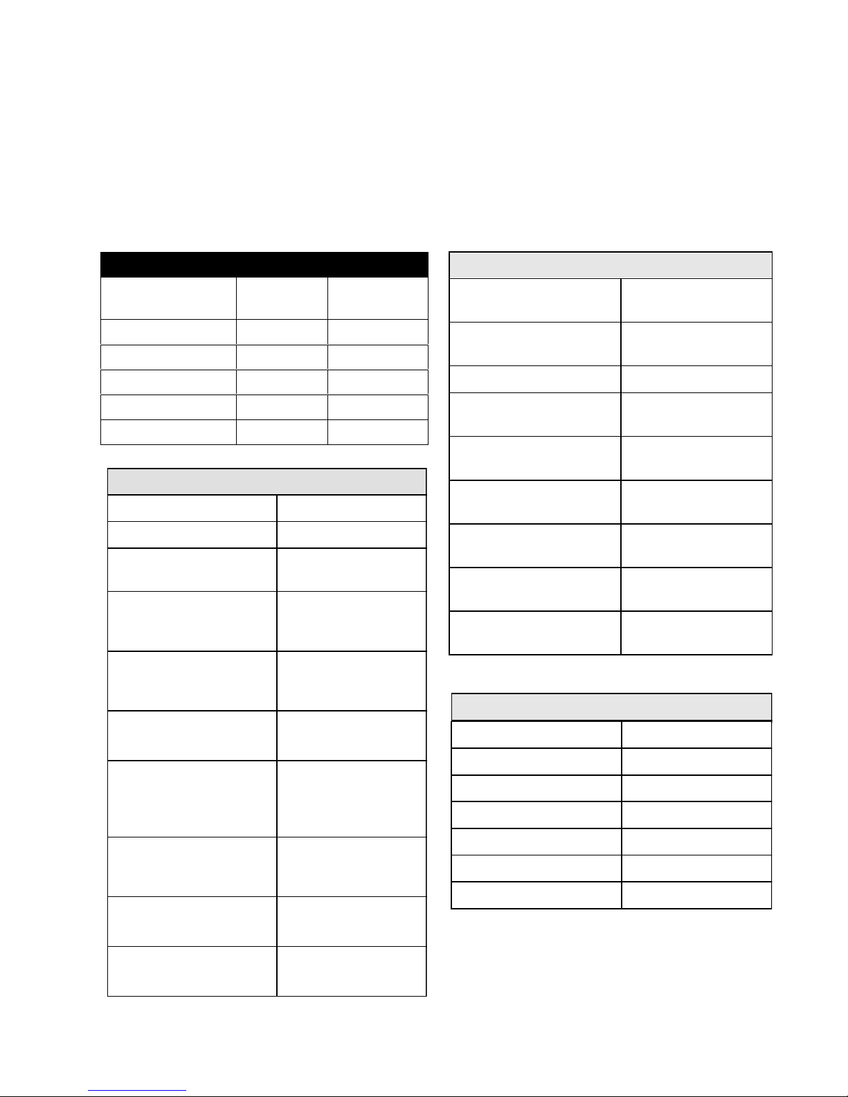
TECHNICAL SPECIFICATIONS
WATER SUPPLY
Suggested Min. Water
Temperature
120° F
Pressure (PSI)
Minimum/Maximum
20/120
Connection (NPT) 3/8"
Water Valve Flow Rate
(GPM)
0.83
Water Fill Time
(± 3 Seconds)
87
Water Volume Per Fill
(Gal.)
1.2
Water Level in Tub
Just to bottom of
element supports
Total Gallons
(normal wash)
6.0
Water Recirculation Rate
(GPM)
12
COMPONENT RESISTANCE - OHMS
PTC Heating Element 9.28
Pump Motor Windings 4.3
Drain Motor Windings 28
Vent Door Actuator 1893
Dispenser Actuator 1928
Water Valve Solenoid 699
Blower Motor 214
For Models: GLDB957JB* ADW750EA*
GLDB958JB* ADW850EA*
GPDB998JC*
* = Color Code
DIAGRAM INDEX
GLDB957JB* B - 1 B - 1
GLDB958JB* B - 1 B - 1
GPDB998JC* B - 1 B - 1
ADW750EA* B - 2 B - 2
ADW850EA* B - 2 B - 2
Rating 120V 60Hz
Separate Circuit 15 Amp
Total Amps (Load
Rated)
Recirculate Motor RPM
Amps
Thermal Cutout Temp.
PTC Heating Element
During Wash Cycle
During Dry Cycle
High Limit Thermostat
opens at
MODEL
NUMBER
CYCLE
CHART
ELECTRICAL
WIRING
DIAGRAM
11.0
3200 ccw
3.4
150° C
900 Watts
700 Watts
200° F
Temp Assure
All cycles except
China/Crystal
Temp Assure
China/Crystal Cycle
Hi-Temp Wash
Hi-Temp Rinse
136° F
Water Temp
127° F
Water Temp
143° F
Water Temp
145° F
Water Temp
Page 5

TEMP ASSURE & HEAT DELAY
OPERATION
WASH CYCLE RINSE CYCLE
OPTIONS SELECTED
High Temp Wash - OFF
High Temp Rinse - OFF
High Temp Wash - OFF
High Temp Rinse - OFF
High Temp Wash - OFF
High Temp Rinse - ON
High Temp Wash - ON
High Temp Rinse - ON
Temp Assure
(*1st potential Delay)
136°F Bypassed 136°F Bypassed
136°F143°F136°F145°F
136°F Bypassed 136°F145°F
136°F143°F136°F145°F
Heat Delay
(*2nd potential delay)
Temp Assure
(*3rd potential Delay)
(*4thd potential delay)
Heat Delay
* Dishwasher will not delay if water is already up to temperature. Maximum delay for each Temp Assure and
Heat Delay interval is 10 minutes.
(Temperatures listed are actual operating temperatures of thermistor.)
Also note that:
Temp Assure water temperature for the China/Crystal cycle is only 127°F.
When High Temp Wash is selected, the potential delay will occur near the end of the 3rd wash cycle.
High Temp Rinse causes a potential delay near the end of the 2nd Rinse cycle (Hi-Temp Rinse is not
used in the China/Crystal cycle) .
Page 6

CONSTRUCTION & OPERATION
WATER DISTRIBUTION SYSTEM
The water distribution system consists of an upper and
lower spray arm, upper (spray) arm delivery tube, filter,
soil director, pump, sump, and check ball. The system
is designed to operate only one spray arm at a time.
During the first wash and first and second rinses, only
the lower spray arm operates. In the second wash, third
and fourth rinses the spray arms alternate about every
90 seconds.
This alternating of the spray arms is achieved with a
check ball located on a ramp between two outlets of the
pump. There is an outlet to the bottom spray arm and an
outlet to the upper arm delivery tube. In the normal
position the ball is at the bottom of the ramp, in front of
the opening to the upper arm delivery tube.
Not all of the water is blocked however. The opening is
constructed to allow a small amount of water to bypass
the ball and enter the tube, and fills the tube at a rate of
approximately four inches a second. At the same time,
the outlet to the lower spray arm is open, so the lower
spray arm operates. When the pump stops, the pressure
is removed from the ball and the water flows down the
tube, forcing the ball up the ramp and against the outlet
to the lower spray arm. If the pump remains off for more
than 3 seconds, all the water in the tube escapes and
the ball returns to the bottom of the ramp. But, if the
pump is started in less than .6 seconds, the water from
the upper arm delivery tube is still forcing the ball up the
ramp against the outlet to the lower spray arm. The
force of the water from the pump continues to hold the
ball against the outlet to the lower spray arm which
leaves the outlet to the upper arm delivery tube open.
When the ball is in this position only the upper spray arm
operates. This momentary stopping of the pump is
controlled by the control board.
Another unique feature of the water distribution system
is the two cavities of the sump. One cavity provides
filtered water to the pump for recirculation through the
spray arms. The other, called a quiet water cavity,
allows soil to collect in the area of the macerator blade,
where it is held until the drain pump removes it.
When the pump starts, the force of the water pushes the
ball to block the opening to the upper arm delivery tube.
WATER DISTRIBUTION COMPONENTS
Wash Pump
The recirculation (wash) pump has three (3) functional
parts, a 1/12th HP drive motor, impeller, and macerator
blade. The pump circulates water at the rate of 12
gallons per minute. This pump is used only during the
wash cycle, a separate pump is used during the drain
cycle. The wash pump is to be replaced as a complete
assembly.
Page 7

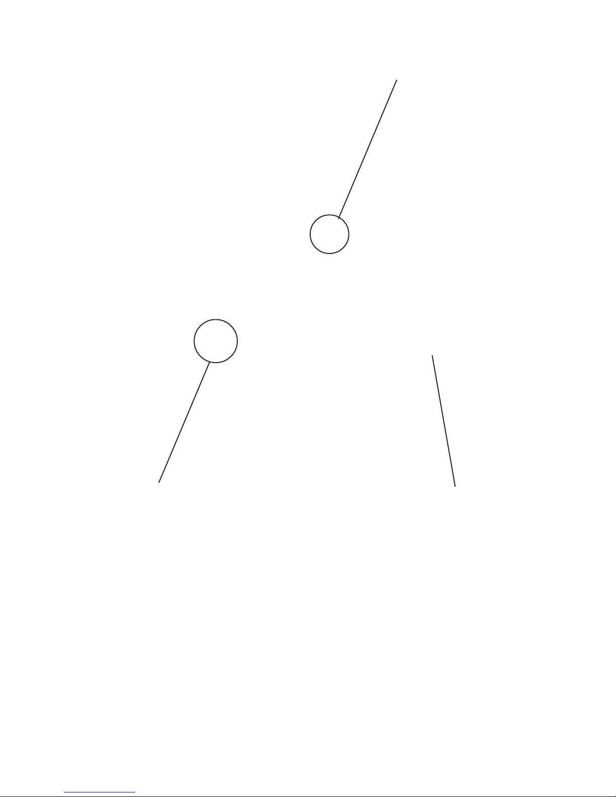
Different Types of Precision Wash Motors
Emerson Motor with Aluminum Motor Mount
ASKO Motor - Phase II Emerson Motor with Phase Mounting Bracket
ASKO Motor - Phase III
Page 8

Upper Spray Arm
The upper spray arm hangs from a bracket that is
snapped to the bottom of the upper rack. The water is
supplied to the arm with a nozzle and funnel
arrangement. The nozzle is located at the top of the tub
and the funnel is located directly below it and directs
water into the arm. All the spray jets but three (3) face
up.
Lower Spray Arm
The lower spray arm rotates on the lower spray arm
support. It has two functions, washing the dishes and
cleaning the filter. The jets located on the top of the arm
clean the dishes and propel the arm. The three (3) jets
located on the bottom of the arm are aimed to flush the
soil on the filter toward the glass trap and soil director.
Drain Pump
The drain pump has only one function, to remove water
from the dishwasher. The drain pump is driven by a 1/
th
HP drive motor. It consists of three (3) functional
25
parts; a pump cover, impeller and armature, and stator.
The quiet cavity and impeller cavity are connected by a
hose underneath the sump. This connection between
the two cavities allows both cavities to be drained.
Filter
The filter consists of two parts, an inner basket
constructed of fine polyester mesh, and an outer filter of
stainless steel.
DRYING SYSTEM
At the start of the dry cycle, a vent opens at the upper
left hand corner of the door allowing the warm moist air
to escape out the front of the control panel. Dry room air
is drawn into the dishwasher tub through an opening
across the bottom of the door. If the heated dry cycle is
selected, the heating element raises the temperature of
the air to increase the evaporation rate and the flow rate
of the air through the dishwasher. These models
incorporate the use of a small motor and centrifugal
blower to accelerate the movement of air through the
dishwasher.
Page 9

The door vent actuator opens the vent only during the
dry cycle. It is closed during all other cycles to minimize
heat loss and to prevent noise from being transmitted
into the kitchen.
DRYING SYSTEM COMPONENTS
Lower Vent Housing
The lower vent housing is located between the inner
door assembly and control housing and is mounted to
the inner door panel. The lower vent housing surrounds
an opening in the inner door panel. This opening is
covered with a moveable vent valve.
Vent Valve
When the timer enters the dry cycle, 120 VAC is applied
to the wax motor. The wax motor is made up of a heating
disk, fluid chamber and piston. When voltage is applied
to the heating disk, it heats the fluid in the chamber
causing the fluid to expand, driving the piston out. The
piston forces the slide out and causes the vent valve to
open.
The vent actuator is replaced as a complete assembly,
no replacement parts are available.
Blower
Electronic control models use a small motor and
centrifugal blower assembly that is mounted to the top
section of the lower vent housing.
The vent valve is a rectangular rubber covered pad
slightly larger than the opening. The vent valve is
attached to the vent actuator which is electrically
operated.
Vent Actuator
The actuator is made up of a rod, slide, wax motor and
spring. The valve is attached to one end of the rod and
the slide is inserted in the other. The spring pushes in
on the slide forcing the rod to push the valve against the
opening in the door panel.
Upper Vent
Housing
Upper Vent Housing
The upper vent housing is screwed to the blower and
directs the air from the blower to the outlet in the
console.
Blower Motor
Actuator
(on rear)
Lower Vent Housing
Vent Valve
Page 10

DISPENSING SYSTEM
DOOR LATCH ASSEMBLY
Detergent & Rinse Aid Dispenser
The detergent and rinse aid dispenser consists of two
dispensers combined in one housing that are controlled
with one wax motor actuator. The first time the actuator
is energized in a cycle it dispenses detergent. The
second time the actuator is energized it dispenses rinse
aid. Using a pointer under the fill cap, the amount of
rinse aid dispensed may be adjusted from one (1) to
four (4) ml. The dispenser is replaced as a complete
assembly, no replacement parts are available. If a more
detailed explanation on how the dispenser operates is
desired; continue.
The dishwasher has two detergent cups, one is the
dispenser that has a spring loaded cover with a manual
or automatic release latch. The other cup is formed in
the inner door panel without a cover. Prior to starting
the dishwasher, detergent is added to the dispenser
cup and the cover is latched closed. The open cup is
also filled but empties into the tub as soon as the door
is lifted to the upright position.
The detergent in the covered cup is held until the start
of the second wash. The timer then supplies 120 VAC
to the dispenser actuator for one minute. It takes about
30 seconds for the actuator to move the pivot arm far
enough to release the cover. When power is applied to
the actuator, the actuator plunger pushes the end of the
pivot arm down. The pivot arm rotates on the shaft of
the detergent dispenser door latch. As the shaft rotates,
it turns the door latch releasing the spring loaded cover.
The pivot arm is spring loaded so that when power is
removed it returns to the normal (horizontal) position.
The other end of the pivot arm has a pin that moves in
a slot(s) of the rinse injector pump arm. The rinse
injector pump arm is slotted in such a way that when
the actuator pushes the lever down the first time to
release the detergent cup cover, the pin moves up but
does not raise the rinse injector pump arm. When the
timer removes power from the actuator, the spring
forces the rinse injector pump arm end of the pivot arm
down. The compound slot in the rinse injector pump
arm directs the pivot arm pin down the front of the rinse
injector pump arm and under a shorter slot in the center
of the arm. When the timer reaches the middle of the
final rinse cycle, it again applies 120 VAC to the
dispenser actuator which forces the pivot arm up at the
rinse injector end. As the pin engages the shorter slot it
raises the rinse injector pump arm which operates the
pump. When the power is removed, the pivot arm
spring forces the pin to the bottom of the slot. A leaf
spring pushes the rinse injector pump arm to the left so
that the pin returns to the original starting position.
The door latch assembly has two functions, one is to
lock the door in a closed position and the other is to
operate the door switches.
The door latch assembly consists of the door handle,
door handle bracket, door catch, door switch bracket
and door switches. The assembly is secured to the
inner door panel with two locator pins and two screws.
The handle is hidden by, and accessed through the
control panel.
When the door is closed, the door strike, mounted on
the tub, forces the spring loaded catch to rotate back
until the bottom of the catch clears the door handle
bracket. At that time the spring forces the door handle
bracket to rotate. The bar on the top of the door handle
rotates back under the door catch locking the door. The
plunger on the bottom of the bracket rotates forward
closing the door switches.
The door is released by lifting up on the door handle.
When the handle is lifted up, the door handle bracket
rotates in at the top, allowing the door catch to rotate
open, and out at the bottom to open the door switches.
When the catch is rotated to the open position, it holds
the door handle bracket away from the door switches.
Page 11

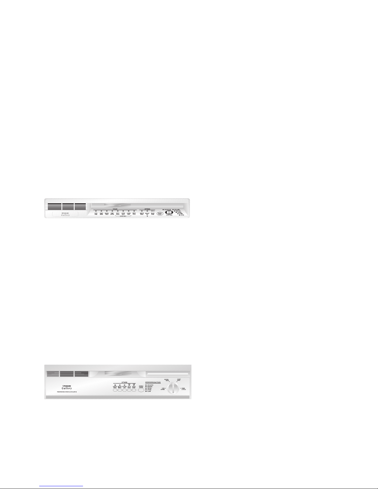
ELECTRONIC CONTROL AND THERMISTOR
There are three styles of electronic controls used in the
Precision Wash System dishwashers. There is a 9 pad
key, 10 pad key and a 12 pad key control. The 12 pad
key is the only one that has the display window for the
time display or the Code display which are:
LO low liquid in the Rinse Aid Dispenser
PF power failure has occurred
HO water heating display
CL close and latch the door
01-09 hours for delay start
The electronic control dishwashers use one thermistor
(instead of two thermostats) to control water temperature
during the various cycles. The thermistor is located
underneath the sump and is controlled by impulses
from the control board.
No Heat Dry
This selection allows the consumer to turn off the
heating element for the drying cycle. If not selected the
element will automatically come on for the dry cycle.
Temp Assure
"Temp Assure" is an automatic water heating function
that ensures that the water in the tub is heated to 140°F
(except for the China/Crystal cycle where the water
temperature 125°F in the main wash cycle and reaches
130°F in the final rinse cycle). "Temp Assure" occurs
near the end of the third wash cycle and near the end of
the second rinse cycle. When the thermistor senses
that the water is cooler than 140°F, it will stat in this no
more than 10 minutes, then the control will advance on
into the cycle whether or not it reached 140°F. This is
designed to keep the dishwasher from running for too
long of a period trying to raise thewater temperature.
Heat Delay
"Heat Delay" is an optional function that must be selected
by the consumer (bypassed for China/Crystal cycle).
"Heat Delay" occurs near the end of the third wash cycle
and near the end of the second rinse cycle right after the
Temp Assure process. "Heat Delay" is controlled by the
Hi-Temp Wash and/or Hi-Temp Rinse touchpads. When
a consumer selects either one or both of these options,
the thermistor stops the cycle from continuing until
either the water reaches 144°F or until 10 minutes have
passed. After 10 minutes the cycle automatically starts
again. This allows the water to be heated and does not
stop the cycle indefinitely.
HIGH LIMIT THERMOSTAT
Located on the left rear tub bottom, the high limit
thermostat is used to prevent the tub from overheating
in the event of a component failure. The thermostat will
open at 200°F.
DISHWASHER LEVELING SYSTEM
The dishwasher is leveled with fout leveling legs and they are screwed into the bottom of the support frame.
There is a 3/16" hex head on top of the leg leveler to help make adjusting of the leg leveler easier by using a
socket on it.
Page 12

TEMPERATURE CONTROLS WITH THERMISTER
The Thermister controls the temperature inside the
dishwasher (Solid State only, depending on what cycle
is selected and what other options are selected).
Functional description are as follows:
CYCLES
Pots & Pans - This is a cycle for heavily soiled
dishes. The control automatically selects an
assured water temperature of 135°F in the main
wash cycle and 140°F in the final rinse. This is
when there are no options selected.
Normal Wash - This cycle is used for normally
soiled dishes. The control automatically selects an
assured water temperature of 135°F in the main
wash cycle and 140°F in the final rinse. This is
when there are no options selected.
China/Crystal - This cycle is used for delicate
china or crystal. The control automatically selects
an assured water temperature of 125°F in the
main wash cycle and 130°F in the final rinse. The
following options are not available for this cycle:
HI-TEMP WASH, HI-TEMP RINSE, SANI RINSE,
or SOIL SENSING OPTIONS.
Both Racks - A cycle used for lightly soiled
dishes. The control automatically selects an
assured water temperature of 135°F in the main
wash cycle and 140°F in the final rinse. All options
plus SOIL SENSING are available
Upper Rack - A cycle used for small loads of
glassware or cups, etc. The control automatically
selects an assured water temperature of 135°F in
the final rinse cycle. The following options are not
available for this cycle: HI-TEMP WASH, HI-TEMP
RINSE, SANI RINSE, or SOIL SENSING
OPTIONS.
OPTIONS
HI-TEMP WASH - Selects both the wash
temperature delay which is 140°F and the rinse
temperature delay which is 145°F. The maximum
delay time is 10 minutes per delay.
HI-TEMP RINSE - Selects only the rinse temperature
delay which is 145°F. The maximum delay time is
10 minutes for this delay.
SANI-RINSE - Selects both the wash temperature
delay which is 145°F and the rinse temperature
delay which is 150°F. At the end of the HI-TEMP
RINSE, an additional 10 minutes of rinsing time is
added to ensure sanitation. The heater will be
cycled on and off to maintain the water temperature
at 150°F. The maximum dalay time is 10 minutes for
the wash temperature delay and 20 minutes for the
rinse delay.
DIRT SENSOR
The true name of the sensor is called the Turbidity
Sensor. It is located just in front of the wash impeller on
the sump. The sensor is mounted by two cross point
head mounting screws.There is a locating tab on the
sensor and a knotch on the sump to ensure the sensor
is intalled correctly. The sensor is a device that senses
how dirty the water is. This is done when the customer
loads the dishwasher with dirty dishes, then starts the
unit. The sensor will then sense how dirty the water is.
The DC output voltage of the sensor will be monitored
at the end of the 30 second pause in the first wash and
the first rinse. If a sufficient quantity of soil exists, the
control will add two additional rinses for a total of eight
fills, or 9.6 gallons of water. Should the sensor detect a
light soil condition, the control will subtract two rinses for
a total of four fills, or 4.8 gallons of water. The Normal
cycle can either increase or decrease the time of a wash
cycle. It just depends on how dirty the water is.
Lower Rack - A cycle used for small loads of pans,
silverware, dishes, etc. The control automatically
selects an assured water temperature of 135°F in
the final rinse cycle. The following options are not
available for this cycle: HI-TEMP WASH, HI-TEMP
RINSE, SANI RINSE, or SOIL SENSING
OPTIONS.
Rinse & Hold - A cycle for rinsing dishes that will
be washed later. No options can be used except
Delay Start.
Controls Locked - The
disables the keyboard but does not interfere with any
cycle in progress. The controls may be locked or
unlocked by depressing NO-HEAT DRY / COOL DRY
on the touch pad for 5 seconds when the door is latched.
The Controls Locked LED is illuminated only when the
control is locked.
Controls Locked
feature
To check to see if the sensor is working properly, start
the dishwasher in the
sensor light to light up on the control panel. If no light is
illuminated, look at the plug on the sensor to ensure that
it is plugged in. After the dishwasher has completed a
wash and rinse cycle, and has filled up again with clean
water, look to make sure the time clock on the control
panel is counting down. If not, turn the power off to the
dishwasher to make it go into the power failure mode.
Then, press and hold the upper rack and start cancel
pad. If any numbers come on in the display area, this
means the sensor is good. If there is no display of
numbers or just blank, then the sensor is bad.
If there is a leak underneath the sensor, check to see if
the sensor was installed correctly. There is a locking tab
on the sensor which lines up with a notch on the sump.
If the sensor is mounted the opposite way, this can
Page 13
Normal
cycle, then look for a

cause a leak down onto the floor. Another leak possibility
is an missing or damaged "O" ring that fits over top of
the covered sensing light of the sensor.
The sensor will not function in the following cycles:
Light Wash (Upper Rack)
Light Wash (Lower Rack)
China / Crystal.
WARNING: WHEN UNPLUGGING THE JUMPER
WIRE THAT YOU USED, MAKE SURE YOU TURN
OFF THE POWER SUPPLY FIRST, UNHOOK
THE TWO WIRES TO THE JUMPER, THEN
RECONNECT WIRE TO CIRCUIT BOARD.
RESTORE POWER.
RINSE AID DISPENSER
The Rinse Aid Dispenser has a circuit board located on
the dispenser to send a signal to the control board
display. When the rinse aid is low with Jet Dry, the board
will send a signal to the display window and will display
a "LO" which indicates that the customer needs to fill the
rinse aid dispenser back up with Jet Dry solution.
NOTE: The "LO" is only shown on the display during the
time the "Clean" light is on.
One way to check to see if you have a bad board when
there is no "LO" displaying is to turn off the power supply
(breaker) and pull off the two wires going to the small
circuit board and use a jumper wire to jump from one
wire to the other. Then, turn the power supply back on.
"PF" should start flashing in the display window. Now,
latch the door and the flashing "PF" should go out. This
is called the "Idle Mode". To go into the "Service Test
Mode", simultaneously press the HI-TEMP WASH &
START/CANCEL pads for 1.5 to 2 seconds. It should
display a 07 in the Display Window. Keep pushing the
START/CANCEL pad until it gets down to the clean
cycle. Here is where the LO should appear in the
display window. When this does come on,this indicates
that there is a defect in the small circuit board on the
detergent assembly. If ther is not a display of "LO", then
this indicates that there is a control board defect, or a
loose or broken wire. Check wires first for continuity. If
ok, replace Control Board.
Page 14
Thermistor
Hi-Limit Thermostat
Drain Pump & Motor
Bottom View
Page 15
DISASSEMBLY
SAFETY PRECAUTIONS
Always turn off the electric power supply before
servicing any electrical component, making ohmmeter
checks, or making any parts replacement. Refer to safe
servicing procedures at the front of this service manual
before servicing the dishwasher.
All voltage checks should be made with a voltmeter
having a full scale range of 130 volts or higher.
After service is completed, be sure all safety grounding
circuits are complete, all electrical connections are
secure, and all access panels are in place.
CONTROL PANEL
1. Disconnect dishwasher from electrical supply.
2. Remove six Phillips screws from top of inner door
panel.
ELECTRONIC KEYPAD - SLIMLINE & REGULAR
1. Disconnect dishwasher from electrical supply.
2. Remove control panel. See "Control Panel."
3. Remove four screws securing protective cover
around control board.
4. Disconnect keypad ribbon from control board.
5. Peal overlay and keypad away from front of control
panel.
6. When replacing overlay and keypad, use denatured
alcohol to get old glue residue off of control panel
face.
7. Remove protective paper from back of new keypad
exposing side with glue.
8. Line up new keypad to corners of control panel and
lay down making sure its straight.
9. Connect new ribbon to control circuit board.
5. Remove cycle selector knob from face of control
panel. See "Selector Switch."
6. Peal overlay and keypad away from front of
control panel.
7. When replacing keypad, use denatured alcohol
to get old glue residue off of control panel face.
8. Remove protective paper from back of new
keypad exposing side with glue.
9. Line up new keypad to corners of control panel
and lay down making sure it's straight.
10. Reconnect ribbons to control circuit board.
11. Replace cycle selector knob. See "Selector
Knob."
CONTROL BOARD - All Electronic Controls
1. Disconnect dishwasher from electrical supply.
2. Remove control panel. See "Control Panel."
3. Remove four screws securing protective cover
around control board.
4. Disconnect keypad ribbons from control board.
5. Disconnect four wire terminals (PT01 - PT04)
from control board.
6. Disconnect large white wiring harness pin
connector from control board.
7. For Selectronic models, remove pin connector
from cycle selector switch.
8. Remove six screws securing control board to
back of control panel.
DOOR PANEL
1. Disconnect dishwasher from electrical supply.
2. The outer door panel is held to the inner door
panel with two locking tabs and two screws.
Loosen the two lower screws securing the
control panel.
3. Remove two screws securing door panel to door
(located at lower section of inner door panel).
4. Slide door panel down and outward to remove.
ELECTRONIC KEYPAD - SELECTRONIC
1. Disconnect dishwasher from electrical supply.
2. Remove control panel. See "Control Panel."
3. Remove four screws securing protective cover
around control board.
4. Disconnect keypad ribbons from control board.
DOOR VENT ASSEMBLY
1. Disconnect dishwasher from electrical supply.
2. Remove outer door panel.
3. Remove control panel.
4. Disconnect wiring to the blower motor and vent
actuator.
5. Remove four Phillips screws securing vent to
inner door panel.
Page 16

VENT VALVE
DETERGENT / RINSE AID DISPENSER
1. Disconnect dishwasher from electrical supply.
2. Remove outer door panel.
3. Disconnect wiring connections.
4. Remove six Phillips screws and carefully push
dispenser into tub.
1. Disconnect dishwasher from electrical supply.
2. Remove outer door panel.
3. Remove control panel.
4. Remove door vent assembly.
5. Slide vent valve upward to remove from actuator
arm.
VENT BLOWER
1. Remove door vent assembly.
2. Remove two screws securing top vent piece.
3. Remove four screws securing lower vent to
blower motor.
DOOR LATCH ASSEMBLY
1. Disconnect dishwasher from electrical supply.
2. Remove outer door panel.
3. The door latch is held to the inner door panel
with two screws and two locator pins. Remove
screws and pull to remove.
4. To remove door switches, push plastic bracket
open and rotate bottom of switch up.
INNER DOOR PANEL
1. To replace inner door panel, remove control
panel, door vent, dispenser and latch.
2. Remove two bolts (T-25 TORX®) from each
hinge and lift off.
DOOR SEAL
1. To remove seal, lift one end and pull entire seal
out.
2. To replace or reinstall seal, center white mark at
top of seal recess and press seal in place, going
left and then right from top center. Do not stretch
seal while installing.
UPPER RACK
1. To remove rack, unsnap and remove retainers at
end of metal track. Once retainers are removed,
pull rack straight out.
Page 17

2. Each rack roller is each secured with a T-25
TORX® bolt.
WATER DISTRIBUTOR
1. The water distributor is screwed to top of upper
arm delivery tube. A rubber seal is used on top
side of tub to eliminate leaks.
KICK PLATE
1. To remove kick plate and insulation (some
models) remove two Phillips screws and pull out
on bottom of kick plate.
UPPER WATER TUBE
1. To remove upper water tube, press in on top of
two clips and lift up.
HEATING ELEMENT
1. Disconnect dishwasher from electrical supply.
2. To remove element, disconnect wiring and
remove two element mounting nuts.
3. Lift terminal ends of element into tub and rotate
element sideways, out of retainers.
UPPER SPRAY ARM
1. To remove upper spray arm, unscrew plastic nut
securing it to support.
Page 18

FLOAT SWITCH AND BRACKET
1. Disconnect dishwasher from electrical supply.
2. To remove float switch bracket, remove outer
door panel, kick plate, and wires to float switch.
A single Phillips screw secures bracket to tub.
3. Remove float switch by spreading mounting
clips.
2. Remove outer door panel and kick plate.
3. Remove hoses and wiring to drain pump.
4. Remove two screws securing drain pump
to mounting bracket.
WATER VALVE
1. Disconnect dishwasher from electrical supply.
2. Remove outer door panel, kick plate, and wires.
3. The water valve is secured with two 5/16" hex
screws.
DRAIN PUMP
1. Disconnect dishwasher from electrical supply.
5. The drain pump assembly consists of three
primary parts, (1) stator winding, (2) motor
armature & impeller, and (3) front housing. To
remove front housing, turn housing about 45°
counterclockwise and lift off.
6. To remove stator winding, release plastic
catches and slide stator winding off.
Page 19
 Loading...