

Frigidaire GLASS DOOR REFRIGERATOR User Manual

FRIGIDAIRE
C O M M E R C I A L
COMMERCIAL FREEZER/REFRIGERATOR
GLASS DOOR REFRIGERATOR
TABLE OF CONTENTS
Product Registration………………………………….…..... 2
Important Safety Instructions……………………….…..... 2
Electrical Information…………………………………........ 3
Caster Installation and Setup (Glass Door)................... 3-4
Caster Installation and Setup (Non-Glass Door).......... 5-6
Appliance Start-up…………………………………............. 6
Features……………………………………………………..... 6-7
Routine Maintenance……………………………………..… 7
Energy Conservation Measures………………………...... 7
Troubleshooting Guide…………………………………...... 8-9
Wiring Diagram……………………………………………....10
Warranty……………………………………………………... 11
READ AND SAVE THESE INSTRUCTIONS 297121600 (June 2006)
Product Registration
These instructions include information which is intended to
assure the operator of correct installation, operation and service.
Before attempting installation, adjustment or maintenance, be
certain of the following:
Important Safety Instructions
Read all instructions before using this appliance
For Your Safety
Do not store or use gasoline or other flammable vapors and
liquids in the vicinity of this unit or any other appliance. Read
product labels for flammability and other warnings.
Child Safety
• Destroy carton, plastic bags, and any exterior wrapping material
immediately after the appliance is unpacked. Children should
never use these items for play. Cartons covered with rugs,
bedspreads, plastic sheets or stretch wrap may become airtight
chambers and can quickly cause suffocation.
• A child might suffocate if he crawls into the appliance to hide
or play. Remove the door/lid of the appliance when not in use,
even if you plan to discard the appliance. Many communities
have laws requiring you to take this safety precaution.
• That you have read and fully understand the instructions.
• That you have all the tools required and are trained to use
them.
• That you have met all installation and usage restrictions and
are familiar with the functions and operations of the unit.
• That you follow all instructions exactly as given.
All the fittings, measurements, recommendations and procedures
are significant. Substitutions and approximations must be
avoided. Improper handling, maintenance, installation and
adjustment, or service attempted by anyone other than a qualified
technician, may void the future warranty claims and cause
damage to the unit and/or result in injury to the operator and/or
bystanders.
Record your Model and Serial Numbers
Record the model number and serial number of this appliance
in the space provided below (the serial plate is located inside
the cabinet compartment).
Model No.
Serial No.
Installation Date
Invoice Date
Start-up Date
Telephone for Service
Proper Disposal of Appliance
Risk of Child Entrapment
Child entrapment and suffocation are not problems of the past.
Junked or abandoned refrigerators or freezers are still dangerous
– even if they will sit for “just a few days”. If you are getting rid of
your old refrigerator or freezer, please follow the instructions
below to help prevent accidents:
• Remove the door.
• Leave shelves in place so children may not easily climb
inside.
• Have the refrigerant removed by a qualified technician.
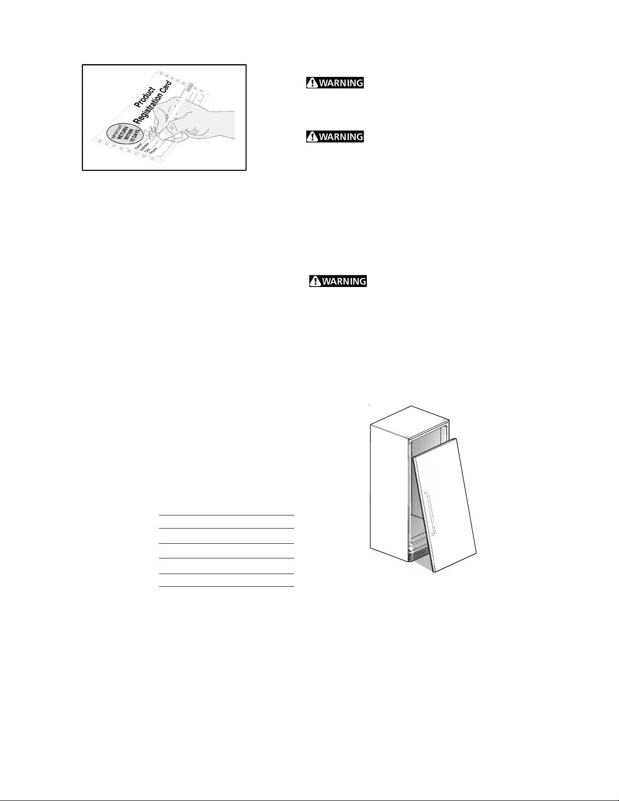
Register Your Product
The self-addressed PRODUCT REGISTRATION CARD (shown
above) should be filled in completely, signed and returned to the
address provided.
2
Electrical Information
These guidelines must be followed to ensure that safety
mechanisms in the design of this appliance will operate
properly.
Avoid fire hazard or
electric shock. Do not use an extension cord
or an adapter plug. Do not remove any
prong from the power cord.
CASTER INSTALLATION AND SET-UP
(Glass Door Only)
Inspect the underside of the cabinet and packaging for damage
such as a fork truck can cause. If hidden damage is found after
uncrating, immediately call the delivery carrier and request an
inspection. Retain all packaging and crating materials until the
inspection is complete.
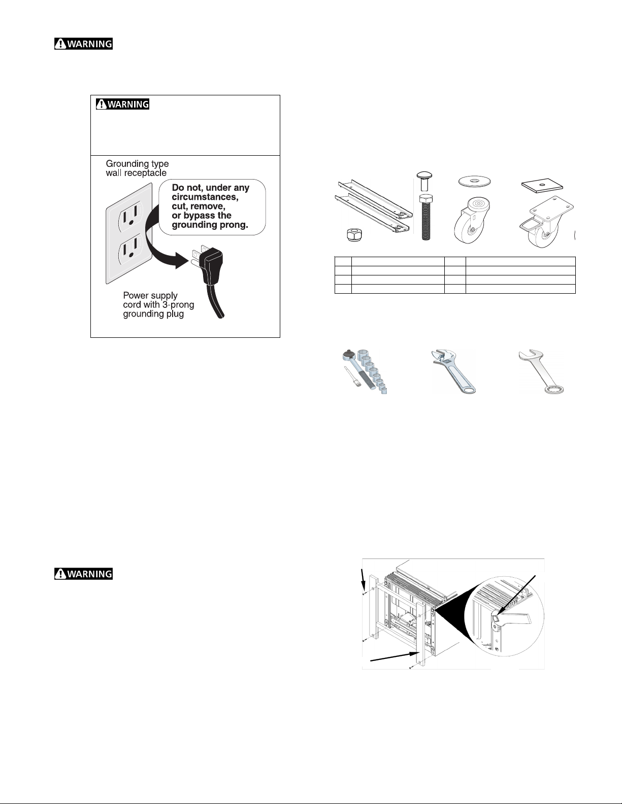
PARTS AND ACCESSORIES
Check to make sure that you have received the box containing
all of the components listed below.
• Refer to the serial plate for correct electrical rating. The
power cord of the appliance is equipped with a three-prong
grounding plug for protection against shock hazards. It must
be plugged directly into its own properly grounded three-prong
receptacle, protected with a 15 amp time delay fuse or circuit
breaker. The receptacle must be installed in accordance with
the local codes and ordinances. Consult a qualified electrician.
Receptacles with Ground Fault Circuit Interrupters (GFCI) are
NOT RECOMMENDED. DO NOT USE AN EXTENSION
CORD OR AN ADAPTER PLUG.
• If the voltage varies by 10 percent or more, appliance
performance may be affected. Operating the appliance with
insufficient power can damage the motor. Such damage is
not covered under the warranty. If you suspect your voltage is
high or low, consult your power company for testing.
• To prevent the appliance from being turned off accidentally,
do not plug the unit into an outlet controlled by a wall switch
or pull cord.
• DO NOT pinch, knot, or bend the power cord in any manner.
A
C
E
G
D
B
A CASTER RAIL (2) E WASHER (4)
B LOCKING NUT (8) F SPACER PLATE (2)
C CARRIAGE BOLT (8) G SWIVEL CASTER (2)
D BOLT (4) H FIXED CASTER W/ BRAKE (2)
TOOLS NEEDED
You will need the following tools to assemble and install the
casters to the unit.
3/8” AND 1/2” INCH
SOCKET WRENCH
UNCRATING AND SET-UP
• Remove carton and all loose parts from inside of the unit.
• Carefully tip the unit onto its back with the help of an assistant.
Lay the unit gently to rest on blocks to avoid damaging the
condensate drain hose and the plastic raceway that covers
the evaporator tubing on the back of the cabinet.
• Remove and discard the wood skid from the bottom and the
four (4) screws using a 3/8" socket wrench (see Fig. 1).
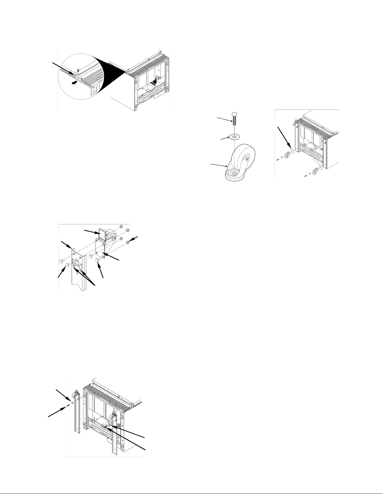
• Using a large adjustable wrench, remove and discard the two
(2) black plastic leg levelers by turning it counterclockwise (see
Fig. 2).
ADJUSTABLE WRENCH
OR PLIERS
F
H
1/2” INCH FIXED
WRENCH
Other Precautions
• NEVER unplug the appliance by pulling on the power cord.
Always grip the plug firmly and pull straight out from the
receptacle.
• To avoid electrical shock, unplug the appliance before
cleaning.
NOTE: Turning the control to “OFF” turns off the compressor
but does not disconnect power to other electrical components.
SCREWS
WOOD SKID
3
LEG LE VELER
Figure 2
Figure 1
• Remove bottom door support bracket and screw opposite the
door hinge using a 3/8" socket wrench (see Fig. 3).
DOOR
SUPPORT
BRACKET
Figure 3
REAR SWIVEL CASTER INSTALLATION
• Place a washer on one of the four long bolts and then feed the
bolt through the hole in one of the swivel casters (see Fig. 6).
• Next, insert that same caster bolt through the hole on the metal
spacer plate and then thru the rear hole of the caster rail (see
Fig. 7).
• Thread the caster bolt into the hole in the bottom-most foot
pad on the unit.
• Tighten both top and bottom bolts securely using a 1/2 inch
fixed or socket wrench.
• Repeat the same procedure on the left hand side. After
installation, carefully tip the unit up with the help of an assistant.
FRONT FIXED CASTER INSTALLATION
• Put two (2) carriage bolts through the rear (non-brake) side of
the fixed caster and hold the carriage bolts loosely in place by
threading several turns on each of the locking nuts. Do not
tighten the bolts yet.
• Hold the caster in position, insert the carriage bolt heads into
slots A & B near the front of the caster rail and slide the caster
back.
• Insert the two (2) front carriage bolts thru the top side of the
caster rail and then thru the front holes on the caster. Attach
locking nuts to each.
• Tighten all locking nuts securely using a 1/2 inch wrench (see
Fig. 4).
• Repeat the same procedure for the other fixed caster.
BRAKE
FRONT OF
CASTER RAIL
CARRIAGE
BOLTS
CARRIAGE BOLTS
SLOTS A&B
LOCKING NUTS
FIXED CASTER
Figure 4
Washer
Swivel
Caster
Figure 6
Bolt
SPACER
PLATE
Figure 7
CASTER RAIL INSTALLATION
• Place a washer onto one of the four long bolts and slide bolt
through the hole located just behind the fixed caster at the
front of caster rail.
• Align the caster rail assembly with the right hand side of the
unit. Make sure the fixed caster is positioned toward the front
of the unit.
• Align the bolt with the threaded hole in the front right foot pad
of the unit. Thread the bolt into the hole until finger tight (see
Fig. 5).
WASHER
BOLT
WASHER
Figure 5
BOLT
4
 Loading...