

Page 1
36 " GAS RANGE INSTALLATION INSTRUCTIONS
B
AKE
S
LOW
C
OOK
B
ROIL
W
ARM
&
H
OLD
O
VEN
L
OCKOUT
S
TOP
C
LEAR
ON/O
FF
O
VEN
L
IGHT
C
LOCK
O
VENCOOK
T
IME
F
LEX
C
LEAN
O
N/OFF
K
ITCHEN
T
IMER
D
ELAY
S
TART
A
DD1
M
INUTE
R
ECIPE
R
ECALL
O
VEN
P
REHEAT
D
OORLOCKED
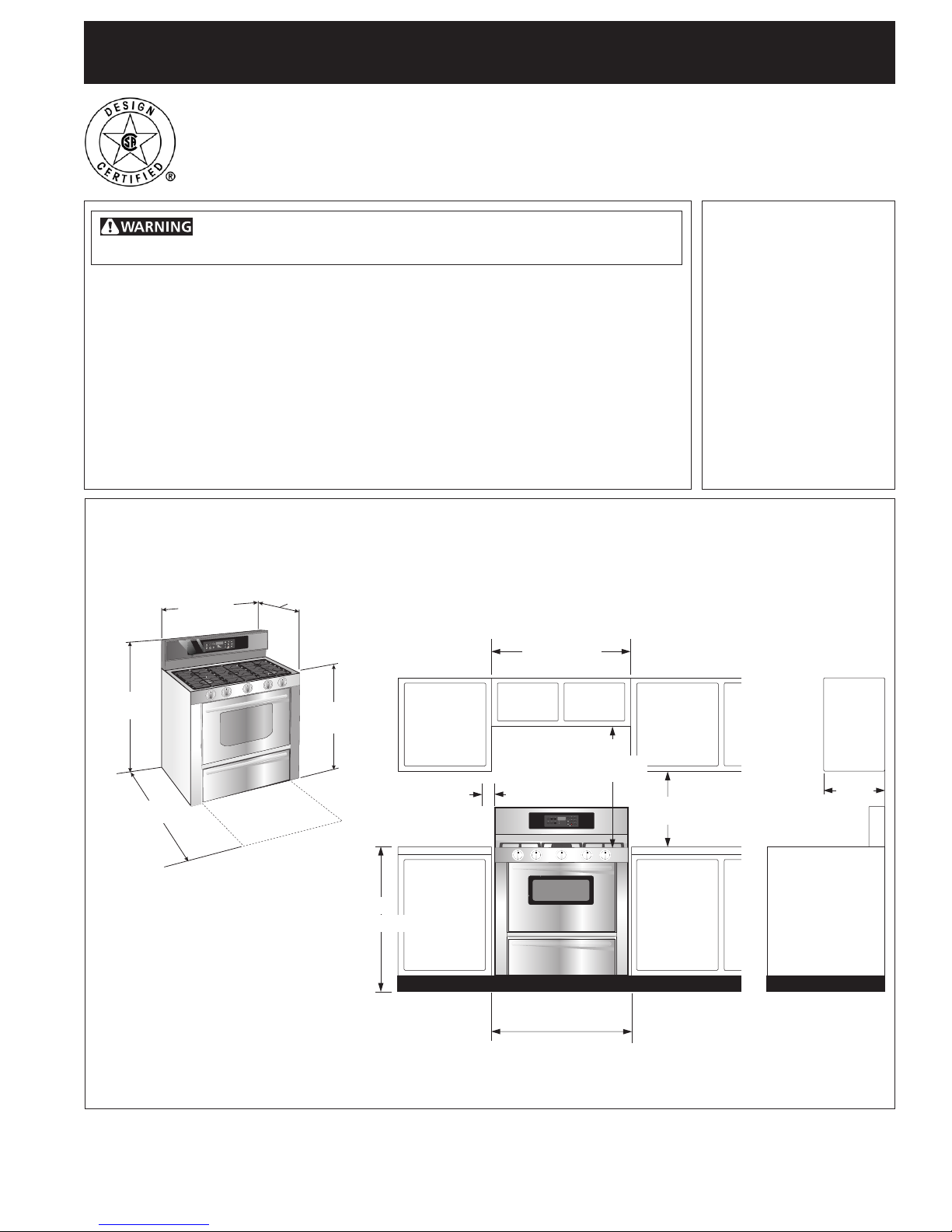
36”
(91.4 cm)
25 5/8”
(65.1 cm)
36”
(91.4 cm)
43 7/8”
(111.4 cm)
47¾”
(121.3 cm)
INSTALLATION AND SERVICE MUST BE PERFORMED BY
A QUALIFIED INSTALLER.
IMPORTANT: SAVE FOR LOCAL ELECTRICAL INSPECTOR'S USE.
READ AND SAVE THESE INSTRUCTIONS FOR FUTURE REFERENCE.
If the information in this manual is not followed exactly, a re
or explosion may result causing property damage, personal injury or death.
FOR YOUR SAFETY:
— Do not store or use gasoline or other ammable vapors and liquids in the
vicinity of this or any other appliance.
— WHAT TO DO IF YOU SMELL GAS:
• Do not try to light any appliance.
• Do not touch any electrical switch; do not use any phone in your building.
• Immediately call your gas supplier from a neighbor's phone. Follow the gas
supplier's instructions.
• If you cannot reach your gas supplier, call the re department.
— Installation and service must be performed by a qualied installer, service
agency or the gas supplier.
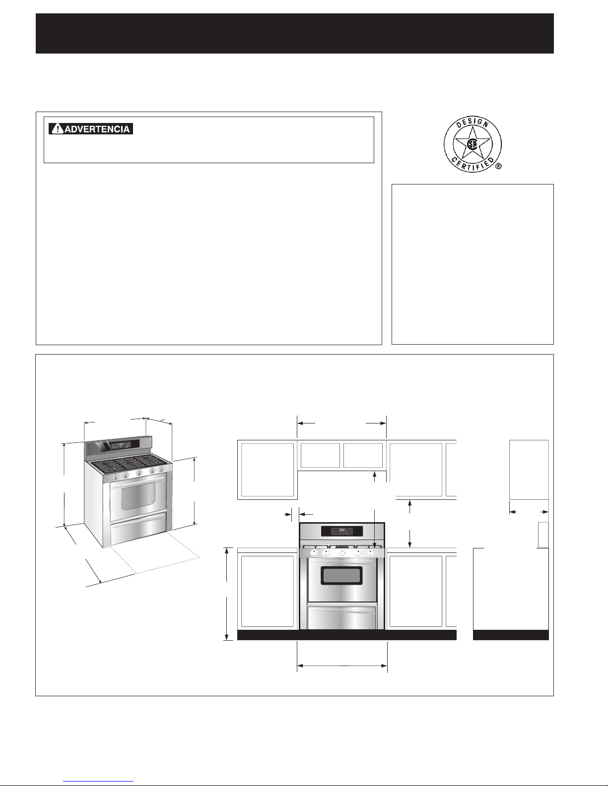
Dimensions and Clearance
Provide adequate clearance between range
and adjacent combustible surfaces.
36" (91.4 cm)
Appliances Installed
in the state of
Massachusetts:
This Appliance can only
be installed in the state
of Massachusetts by a
Massachusetts licensed
plumber or gastter.
This appliance must be
installed with a 3 foot (36 in.)
long exible gas connector.
A "T" handle type manual
gas valve must be installed
in the gas supply line to this
appliance.
(76.2 cm)
Minimum clearance on
either side of range
5" (12.7 cm)
Minimum
above 36" (91.4 cm)
height if a wall is
installed
Wall
36"
(91.4 cm)
36¼" (92.1 cm)
Between Cabinets
Figure 1
NOTE: Wiring diagram for this appliance is enclosed in this booklet.
Printed in United States
1
30"
18"
(45.7 cm)
Minimum to cabinets on
either side
of range
Maximum depth
for cabinets
above range top
0" Min. Clearance
at rear of range
below cooktop
from the back wall.
P/N 318201765 (1302) Rev. B
English – pages 1-7
Español – páginas 8-15
Wiring Diagram - pages 16
13"
(33 cm)
Page 2
36" GAS RANGE INSTALLATION INSTRUCTIONS
1. Read all instructions contained in these installation
instructions before installing range.
2. Remove all packing material from the oven
compartments before connecting the gas and
electrical supply to the range.
3. Observe all governing codes and ordinances.
4. Be sure to leave these instructions with the consumer.
5. Note: For operation at 2000 ft. elevations above see
level, appliance rating shall be reduced by 4 percent
for each additional 1000 ft.
Keep these instructions with your Use & Care Guide for
future reference.
Important Note to the Consumer
Keep these instructions with your Use & Care Guide for
future reference.
IMPORTANT SAFETY
INSTRUCTIONS
Installation of this range must conform with local codes
or, in the absence of local codes, with the National Fuel
Gas Code ANSI Z223.1/NFPA .54-latest edition.
This range has been design certied by CSA
International. As with any appliance using gas and
generating heat, there are certain safety precautions
you should follow. You will nd them in the Use and
Care Guide, read it carefully.
• Air curtain or other overhead hoods, which
operate by blowing a downward air flow on
to a range, shall not be used in conjunction
with gas ranges other than when the hood and
range have been designed, tested and listen
by an independent test laboratory for use in
combination with each other.
• Be sure your range is installed and grounded
properly by a qualied installer or service
technician.
• This range must be electrically grounded
in accordance with local codes or, in their
absence, with the National Electrical Code
ANSI/NFPA No. 70—latest edition. See
Grounding Instructions.
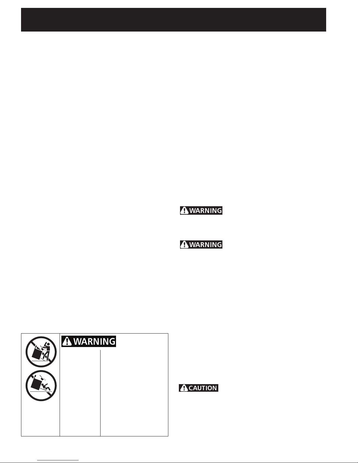
• All ranges
can tip.
• Injury to
persons
could
result.
• Install anti-
tip device
packed with
range.
To reduce the risk of
tipping of the range, the
range must be secured
by properly installed antitip bracket (s) provided
with the range. To
check if the bracket(s) is
installed properly, grasp
the top rear edge of the
range and carefully tilt it
forward to make sure the
range is anchored.
• The installation of appliances designed for
manufactures (mobile) home installation must
conform with Manufactured Home Construction and
Safety Standard, title 24CFR, part 3280 [Formerly
the Federal Standard for Mobile Home Construction
and Safety, title 24, HUD (part 280)] or when
such standard is not applicable, the Standard for
Manufactured Home Installation 1982 (Manufactured
Home Sites, Communities and Set ups), ANSI Z225.1
latest edition, or local codes.
• Before installing the range in an area covered with
linoleum or any other synthetic floor covering,
make sure the oor covering can withstand heat
at least 90°F above room temperature without
shrinking, warping or discoloring. Do not install the
range over carpeting unless you place an insulating pad
or sheet of ¼" (10,16 cm) thick plywood between the
range and carpeting.
• Make sure the wall coverings around the range
can withstand the heat generated by the range.
• Do not obstruct the ow of combustion air at
the oven vent nor around the base or beneath
the lower front panel of the range. Avoid touching
the vent openings or nearby surfaces as they may
become hot while the oven is in operation. This range
requires fresh air for proper burner combustion.
Never leave children alone or
unattended in the area where an appliance is
in use. As children grow, teach them the proper, safe
use of all appliances. Never leave the oven door open
when the range is unattended.
Stepping, leaning or sitting on
the doors or drawers of this range can result in
serious injuries and can also cause damage to
the range.
• Do not store items of interest to children in
the cabinets above the range. Children could be
seriously burned climbing on the range to reach items.
• To eliminate the need to reach over the
surface burners, cabinet storage space above
the burners should be avoided.
• Adjust surface burner ame size so it does not
extend beyond the edge of the cooking utensil.
Excessive ame is hazardous.
• Do not use the oven as a storage space. This
creates a potentially hazardous situation.
• Never use your range for warming or heating
the room. Prolonged use of the range without
adequate ventilation can be dangerous.
• Do not store or use gasoline or other
ammable vapors and liquids near this or any
other appliance. Explosions or res could result.
Do not make any attempt to
operate the electric ignition oven during an
electrical power failure. Resumption of electric
power when OVEN TEMP and OVEN SET controls
are in any position other than OFF will result in
automatic ignition of the oven or broiler burner. The
2
Page 3
36 " GAS RANGE INSTALLATION INSTRUCTIONS
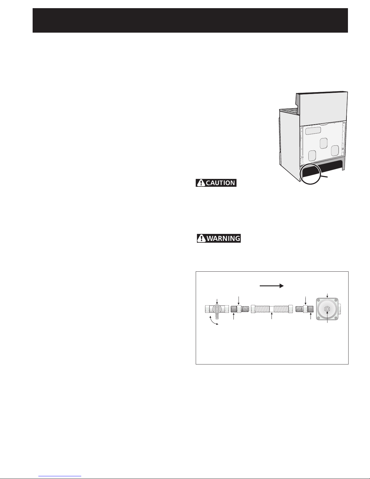
Flare
Union
Flare
Union
GAS FLOW
Manual
Shutoff
Valve
Pressure
Regulator
On
Off
Flexible
Connector
Access
Cap
Nipple Nipple
oven burner and broil burner on your range
are lighted by electrical ignition. The oven and
broiler cannot be operated in the event of a
power failure.
• In the event of an electrical power outage, the
surface burners can be lit manually. To light a
surface burner, hold a lit match to the burner head
and slowly turn the Surface Control knob to LITE.
Use caution when lighting surface burners manually.
• Reset all controls to the "off" position
whenever the oven is done cooking.
FOR MODELS WITH SELF-CLEAN FEATURE:
• Remove broiler pan, food and other utensils
before self-cleaning the oven. Wipe up excess
spillage. Follow the precleaning instructions in the
Use and Care Guide.
• Unlike the standard gas range, THIS COOKTOP
IS NOT REMOVABLE. Do not attempt to remove
the cooktop.
1. Before Installing the Range
Remove shipping material
Remove all tape, shipping and packaging materials and
the oven rack packaging.
2. Provide an adequate Gas Supply
When shipped from the factory, this unit is designed
to operate on 4"(10,16 cm) water column (1.0 kPa)
Natural gas manifold pressure. A convertible pressure
regulator is connected to the range manifold and
MUST be connected in series with the gas supply line.
If LP/Propane conversion kit has been used, follow
instructions provided with the kit for converting the
pressure regulator to LP/Propane use.
3. Seal the openings
Seal any openings in the wall behind the range and
in the oor under the range after gas supply line is
installed.
4. Connect the range to the gas
supply
Important: Remove
all packing material and
literature from range before
connecting gas and electrical
supply.
To prevent leaks, put pipe
joint sealant on all external
pipe threads.
Your regulator is in location
shown below.
Do not
allow regulator to rotate
on pipe when tightening
ttings.
Figure 2
Connection to Pressure Regulator
The regulator is already installed on the appliance.
Do not make the connection too
tight. The regulator is die cast. Overtightening may
crack the regulator resulting in a gas leak and possible
re or explosion.
Pressure
Regulator
Location
Care must be taken during installation of range not to
obstruct the ow of air for combustion and ventilation.
For proper operation, the maximum inlet pressure
to the regulator should be no more than 14"(35,56
cm) of water column pressure (3.5 kPa). The inlet
pressure to the regulator must be at least 1" (.25 kPa)
greater than the regulator manifold pressure setting.
Examples: If regulator is set for natural gas 4"(10,16
cm) manifold pressure, inlet pressure must be at least
5"(12.60 cm); if regulator has been converted for LP/
Propane gas 10"(25,4 cm) manifold pressure, inlet
pressure must be at least 11"(27,9 cm).
Leak testing of the appliance shall be conducted
according to the instructions in step 4.
The gas supply line should be ½" or ¾" I.D. (Interior
Diameter)
All connections must be wrench-tightened
Figure 3
Assemble the exible connector from the gas supply
pipe to the pressure regulator in the following order:
1. manual shutoff valve (not included)
2. 1/2" nipple (not included)
3. 1/2" are union adapter (not included)
4. exible connector (not included)
5. 1/2" are union adapter (not included)
6. 1/2" nipple (not included)
7. pressure regulator (Included)
3
Page 4
36" GAS RANGE INSTALLATION INSTRUCTIONS
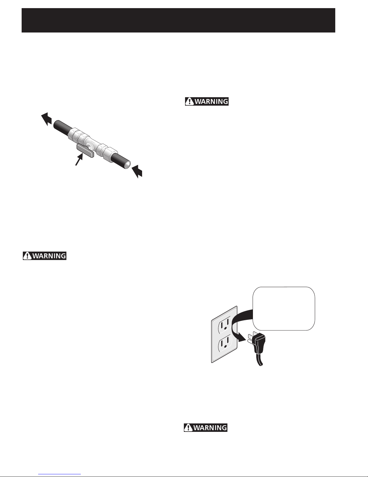
Manual Shutoff Valve -
Open position
to appliance
From gas supply line
Use pipe-joint compound made for use with Natural and
LP/Propane gas to seal all gas connections. If flexible
connectors are used, be certain connectors are not kinked.
The supply line must be equipped with an approved
manual shutoff valve. This valve should be located
in the same room as the range and should be in a
location that allows ease of opening and closing. Do
not block access to the shutoff valve. The valve is for
turning on or shutting off gas to the appliance.
Figure 4
Once regulator is in place, open the shutoff valve in
the gas supply line. Wait a few minutes for gas to
move through the gas line.
Check for leaks. After connecting the range to the gas
supply, check the system for leaks with a manometer.
If a manometer is not available, turn on the gas supply
and use a liquid leak detector (or soap and water) at all
joints and connections to check for leaks.
Do not use a ame to check for leaks
from gas connections. Checking for leaks with a ame
may result in a re or explosion.
Tighten all connections as necessary to prevent gas
leakage in the range or supply line.
Disconnect this range from the gas supply piping
system during any pressure testing of that system at
test pressures greater than 1/2 psig (3.5 kPa or 14"
water column).
Isolate the range from the gas supply piping
system by closing its individual manual shutoff valve
during any pressure testing of the gas supply piping
system at test pressures equal to or less than 1/2 psig
(3.5 kPa or 14" water column).
The conversion must be performed by a qualied
service technician in accordance with the
manufacturer's instructions and all local codes and
requirements. Failure to follow these instructions
could result in serious injury or property damage.
The qualied agency performing this work assumes
responsibility for the conversion.
Failure to make the appropriate
conversion can result in serious personal injury and
property damage.
6. Electrical Requirements
120 volt, 60 Hertz, properly grounded dedicated circuit
protected by a 15 amp circuit breaker or time delay
fuse. NOTE: This range is not recommended to be
installed with a Ground Fault Interrupt (GFI).
Do not use an extension cord with this range.
Grounding Instructions
IMPORTANT Please read carefully.
For personal safety, this appliance must be
properly grounded.
The power cord of this appliance is equipped with a
3-prong (grounding) plug which mates with a standard
3-prong grounding wall receptacle (see Figure 5) to
minimize the possibility of electric shock hazard from
the appliance.
The wall receptacle and circuit should be checked by
a qualied electrician to make sure the receptacle is
properly grounded.
Preferred Method
Grounding type
wall receptacle
Figure 5
Do not, under any
circumstances,
cut, remove,
or bypass the
grounding prong.
Power supply cord with
3-prong grounding plug.
5. LP/Propane Gas Conversion
This appliance can be used with Natural gas or LP/
Propane gas. It is shipped from the factory for use
with natural gas.
The range comes supplied with xed orices for
converting it to LP gas. These orices are located in a
bag marked FOR LP/PROPANE GAS CONVERSION. The
instructions for surface, oven and broil burner conversion
are packaged with the orices.
Where a standard 2-prong wall receptacle is installed,
it is the personal responsibility and obligation of the
consumer to have it replaced by a properly grounded
3-prong wall receptacle.
Do not, under any circumstances, cut or remove
the third (ground) prong from the power cord.
Disconnect electrical supply cord from
wall receptacle before servicing range.
4
Page 5
36 " GAS RANGE INSTALLATION INSTRUCTIONS
Electrodes
must align into slot
for each Burner Head
Figure 6B
Figure 6A
7. Moving the Appliance for
Servicing and Cleaning
Turn off the range line fuse or circuit breakers at the
main power source, and turn off the manual gas shutoff valve. Make sure the range is cold. Remove the
service drawer (warmer drawer on some models) and
open the oven door. Lift the range at the front and
slide it out of the cut-out opening without creating
undue strain on the exible gas conduit. Make sure
not to pinch the exible gas conduit at the back of
the range when replacing the unit into the cut-out
opening. Replace the drawer, close the door and
switch on the electrical power and gas to the range.
8. Check Operation
Refer to the Use and Care Guide packaged with the
range for operating instructions and for care and
cleaning of your range.
Remove all packaging from the oven before testing.
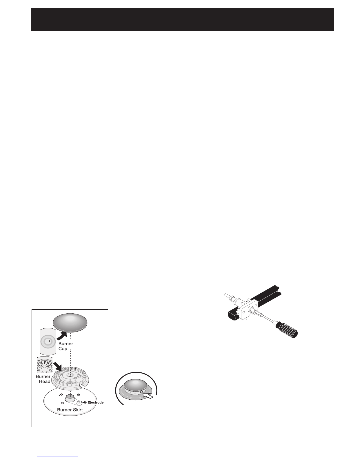
8.1 Install Burner Bases and Burner Caps
This range is equipped with sealed
burners as shown (see Figure 6).
It is very important to make sure that all of the Surface
Burner Heads, Surface Burner Caps and Surface Burner
Grates are installed correctly.
1. Remove all packing tape from cooktop. Remove
Burner Caps and Burner Heads (See Figure 6A).
2. Discard all packing material located under all Burner
Heads.
3. To correctly place Burner Heads & Caps, match the
letters located under center of Burner Caps with the
letters located inside Burner Head (See Figure 6A).
4. Match the letters stamped on Burner skirts with
Burner Heads and Burner Caps on cooktop. Carefully
align the Electrodes into slots of the Burner Heads
(Figure 6B). Note: The Burner Heads should sit at on
Cooktop Burner Skirts.
5. Unpack Burner Grates
and position on cooktop.
NOTE: There are no
burner adjustments
necessary on this range.
8.2 Turn on Electrical Power and Open
Main Shutoff Gas Valve
8.3 Check the Igniters
Operation of electric igniters should be checked after
range and supply line connectors have been carefully
checked for leaks, and range has been connected to
electric power. To check for proper lighting:
a. Push in and turn a surface burner knob to the LITE
position. You will hear the igniter sparking.
b. The surface burner should light when gas is
available to the top burner. Each burner should light
within four (4) seconds after air has been purged
from supply lines. Visually check that burner has lit.
c. Once the burner lights, the control knob should be
rotated out of the LITE position.
There are separate ignition devices for each burner.
Try each knob separately until all burner valves have
been checked.
8.4 Adjust the "LOW" Setting of Surface
Burner Valves (see Figure 7)
a. Push in and turn each control to LITE until burner
ignites.
b. Quickly turn knob to LOWEST POSITION.
c. If burner goes out, readjust valve as follows:
Reset control to OFF. Remove the surface burner
control knob, insert a thin-bladed screw driver into
the hollow valve stem and engage the slotted screw
inside. Flame size can be increased or decreased
with the turn of the screw. Adjust ame until
you can quickly turn knob from LITE to LOWEST
POSITION without extinguishing the ame. Flame
should be as small as possible without going out.
Figure 7
8.5 Operation of Oven Burners and Oven
Adjustments
8.5.1 Electric Ignition Burners
Operation of electric igniters should be checked after
range and supply line connectors have been carefully
checked for leaks, and range has been connected to
electric power.
The oven burner is equipped with an electric control
system as well as an electric oven burner igniter. If your
model is equipped with a waist-high broil burner igniter,
it will also have an electric burner igniter. These control
5
Page 6
36" GAS RANGE INSTALLATION INSTRUCTIONS
systems require no adjustment. When the oven is set
to operate, current will ow to the igniter. It will "glow"
similar to a light bulb. When the igniter has reached
a temperature sufficient to ignite gas, the electrically
controlled oven valve will open and ame will appear at the
oven burner. There is a time lapse from 30 to 60 seconds
after thermostat is turned ON before the ame appears
at the oven burner. When the oven reaches the display
setting, the glowing igniter will go off. The burner ame
will go "out" in 20 to 30 seconds after igniter goes "OFF".
To maintain any given oven temperature, this cycle will
continue as long as the display is set to operate.
After removing all packing materials and literature from
the oven:
a) Set the oven to BAKE at 300°F. See Use & Care Guide
for operating instructions.
b) Within 60 seconds the oven burner should ignite.
Check for proper ame (see 8.5.2), and allow the
burner to cycle once (see cycle explanation above).
Reset controls to off.
c) If your model is equipped with a waist-high broiler
burner, set oven to broil. See Use & Care Guide for
operating instructions.
d) Within 60 seconds the broil burner should ignite. Check
for proper ame (see 8.5.3). Reset controls to off.
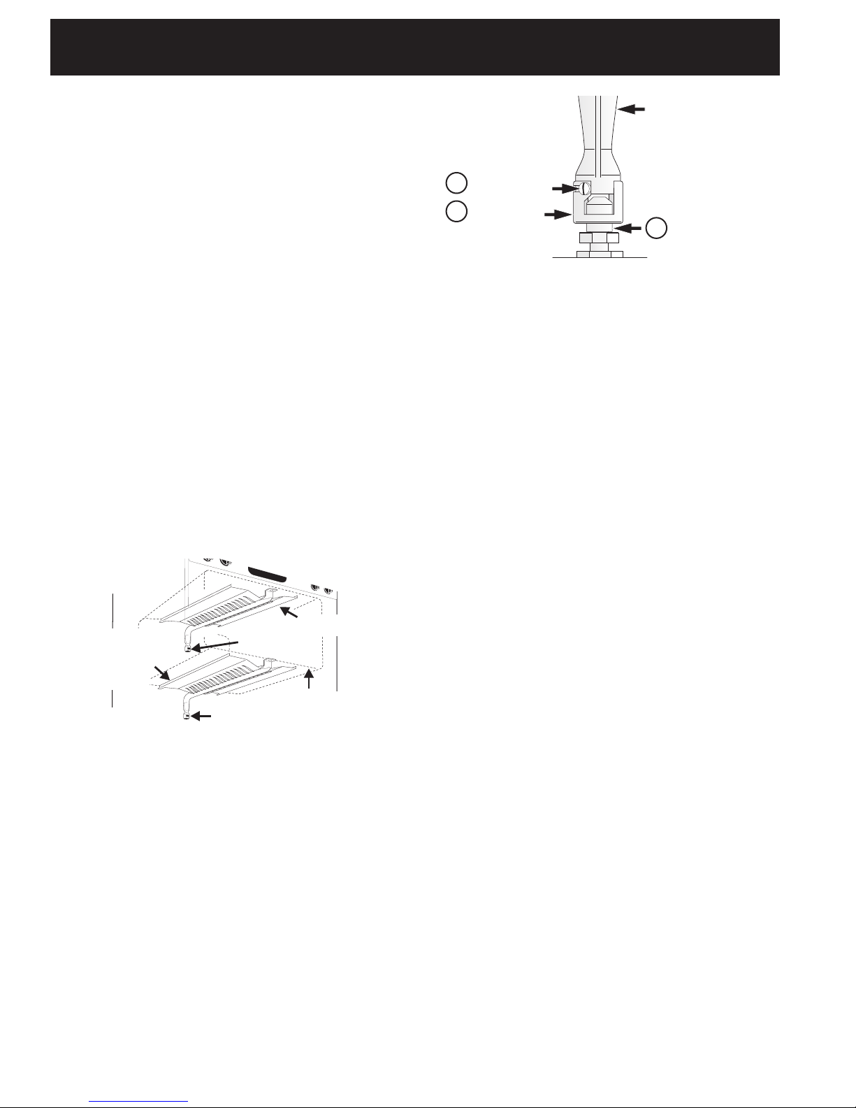
8.5.2 Oven Burner Flame Adjustment
Oven Burner Tube
3
Lock Screw
2
Air Shutter
Figure 9
8.5.3 Broil Burner Flame Adjustment
The approximate ame length of the burner is 1 inch
(distinct inner cone of blue ame). To determine if the
broil burner ame is proper, set the oven to broil. If
ame is yellow, increase air shutter opening size (see "2"
in Figure 9 ). If the entire ame is blue, reduce the air
shutter opening size. To adjust, loosen lock screw (see
"3" in Figure 9), reposition air shutter, and tighten lock
screw.
Orice Hood
1
9. Make Sure Range Is Level
Check if the range is level by placing a level horizontally
on an oven rack. Check diagonally from front to back,
then level the range by either adjusting the leveling legs
or by placing shims under the corners of the range as
needed.
Lower
Oven Burner
Bafe
(removable)
Figure 8
The approximate oven burner ame length is 1 inch
(distinct inner cone of blue ame).
To determine if the oven burner ame is proper, remove
the oven bottom and burner bafe and set the oven to
bake at 300°F.
To remove the oven bottom, remove oven hold down
screws at rear of oven bottom. Pull up at rear, disengage
front of oven bottom from oven front frame, and pull the
oven bottom out of the oven. Remove burner bafe so
that burner ame can be observed.
If the ame is yellow, increase air shutter opening size
(see "2" in Figure 9). If the entire ame is blue, reduce
the air shutter opening size.
To adjust ame loosen lock screw (see "3" in Figure 9),
reposition air shutter, and tighten lock screw. Replace
oven bottom.
Air Shutter
Waist-High Burner
Air Shutter
Lower Oven Bottom
(removable)
When All Hookups are Complete
Make sure all controls are left in the OFF position.
Make sure the ow of combustion and ventilation air to
the range is unobstructed.
Model and Serial Number Location
The serial plate is located on the oven front frame
behind the drawer.
When ordering parts for or making inquiries about
your range, always be sure to include the model and
serial numbers and a lot number or letter from the
serial plate on your range.
Your serial plate also tells you the rating of the
burners, the type of fuel and the pressure the range
was adjusted for when it left the factory.
Before You Call for Service
Read the Before You Call for Service Checklist and
operating instructions in your Use and Care Guide.
It may save you time and expense. The list includes
common occurrences that are not the result of
defective workmanship or materials in this appliance.
Refer to the warranty in your Use and Care Guide for
our service phone number and address. Please call or
write if you have inquiries about your product and/or
need to order parts.
6
Page 7
36 " GAS RANGE INSTALLATION INSTRUCTIONS
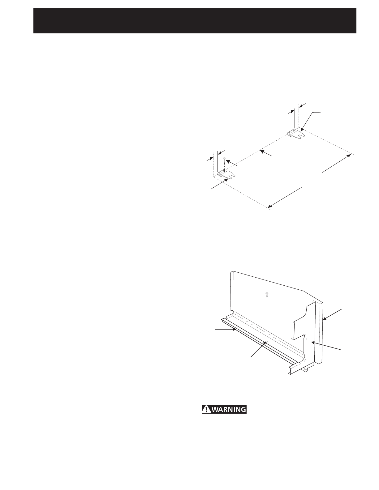
10. Anti-tip Bracket Installation
Important Safety Warning
This range must be properly secured to the oor
by using the included anti-tip brackets and screws.
Failure to install the brackets could allow the range
to accidentally tip over if excessive weight is placed
on an open door or if a child climbs upon it. Serious
injury might result from spilled hot liquids or from the
range itself. Refer to the instructions below for proper
installation (Figure 10).
NOTE: If the range is ever moved to a different
location, the anti-tip brackets must also be moved and
installed with the range.
The anti-tip kit is located in a plastic bag in the
oven.
Tools Required:
5/16” Nutdriver or Flat Head Screwdriver
Adjustable Wrench
3/16” Dia. Masonry Drill Bit (if installing in concrete)
Attach brackets to the oor at the back of the range
to hold both rear leg levelers. When fastening to the
oor, be sure that screws do not penetrate electrical
wiring or plumbing. The screws provided will work in
either wood or concrete.
Range may be anchored to oor in a house with hold
down brackets as illustrated in Figure 10. These hold
down brackets allow range to be freely pulled out from
the wall for cleaning or servicing without the use of
tools.
1. Attach brackets to the oor or rear wall with screws
provided. Important: Attachment must be secured
to solid oor or wall. Do not attach to plaster, sheet
rock, or other soft material. If attachment is to rear
wall, any moldings must be removed in area behind
range.
2. If brackets are to be attached to masonry or
ceramic oors, position brackets on oor and mark
hole location. Drill 3/16” holes.
3. Lower both rear leg levelers about three turns so
the brackets will slide over leveler head.
4. Level the range front to back and side to side with
the two front leg levelers and the rear levelers.
5. Slide range into place making sure rear legs are
trapped by ends of brackets. Range may need to
be shifted slightly to one side as it is being pushed
back to allow rear legs to align with brackets.
Remove lower panel or storage drawer to inspect
brackets or grasp the top rear edge of the range
and carefully attempt to tilt it forward to make sure
range is properly anchored.
3
/8"
3
/8"
2 Screws
Per Bracket
Install Hold
Down Bracket
For mobile homes, the range must be anchored to the
oor as illustrated in Figure 11.
1. Remove false panel or storage drawer to gain
access to the anchoring holes.
2. A 1/4” diameter hole is provided in the center of
each base rail for anchoring to oor.
Base
Rail
Hole For Anchoring
Range to Floor;
Hole Located Approx.
Midpoint of Base Rail.
Back Edge of Range
or Rear Wall
Range Side
Panel Location
Figure 10
Install Hold
Down Bracket
Body
Side
Front
Frame
Figure 11
Stepping, leaning or sitting on the door
or drawer of this range can result in serious injuries and
also cause damage to the range.
7
Page 8
INSTRUCCIONES DE INSTALACIÓN PARA LA ESTUFA A GAS DE 36"
B
AKE
S
LOW
C
OOK
B
ROIL
W
ARM
&
H
OLD
O
VEN
L
OCKOUT
S
TOP
CLEAR
ON/O
FF
O
VEN
L
IGHT
C
LOCK
O
VENCOOK
T
IME
F
LEX
C
LEAN
O
N/OFF
K
ITCHEN
T
IMER
D
ELAY
S
TART
A
DD1
M
INUTE
R
ECIPE
R
ECALL
O
VEN
P
REHEAT
D
OORLOCKED
36”
(91.4 cm)
25 5/8”
(65.1 cm)
36”
(91.4 cm)
43 7/8”
(111.4 cm)
47¾”
(121.3 cm)
LA INSTALACIÓN Y EL SERVICIO DEBEN SER EFECTUADOS POR UN INSTALADOR
CALIFICADO.
IMPORTANTE: GUARDE ESTAS INSTRUCCIONES PARA USO DEL INSPECTOR LOCAL DE
ELECTRICIDAD. LEA Y GUARDE ESTAS INSTRUCCIONES PARA REFERENCIA FUTURA.
Si todas las instrucciones de éste manual no son
observadas a la letra, se puede ocurrir incendios o explosiones que
pueden causar daños materiales, lesiones o la muerte.
– No almacene o utilice gasolina u otros vapores y líquidos
inamables cerca de este o cualquier otro artefacto.
– QUE HACER SI HAY FUGAS DE GAS
• No intente de encender ningún artefacto
• No toque ningún interruptor eléctrico; no utilice ningún
aparato telefónico en su edicio.
• Llame inmediatamente el abastecedor de gas desde el
telefónico
de un vecino. Siga las instrucciones del abastecedor de
gas
• En caso que no puede contactar el abastecedor de gas,
llame al departamento de bomberos.
– La instalación y el servicio técnico deben ser realizados por
un instalador calicado, por un servicio técnico certicado o
por el abastecedor de gas.
Aparatos Instalados en el
estado de Massachusetts;
Este Aparato sólo puede ser instalado
en el estado de Massachusetts por un
plomero o ajustador de gas licenciado
de Massachusett.
Este aparato se debe instalar con un
largo conector exible de gas de tres
(3) pies/36 pulgadas.
Una válvula manual de gas de tipo
manija de forma de "T" se debe
instalar en la línea del suministro de
gas de este aparato.
Dimensiones y espacios libres
Provee adecuados espacios libres entre la estufa y las supercies combustibles adyacentes
36" (91.4 cm)
30"
(76.2 cm)
Espacio libre mín. hasta
la pared a cualquier lado
5" (12.7 cm)
de la estufa superior a
36" (91.4 cm) de altura.
Pared
36"
36¼" (92.1 cm)
entre los gabinetes
Figura 1
NOTA: Se adjunta los diagramas de cables de estas estufas con el libreta.
Impreso en los Estados Unidos
8
Mínimo
(45.7 cm)
18"
Mínimo hasta
los gabinetes a
cualquier lado
de la estufa.
Diagrama de la instalación alambica - paginas 16
13"
(33 cm)
Profundidad
máxima para los
gabinetes que
se encuentran
por arriba de la
estufas
Separación mínima de
0" en la parte posterior
de la estufa debajo de la
cubierta de la pared trasera
P/N 318201765 (1302) Rev. B
English – pages 1-7
Español – paginas 8-15
Page 9
INSTRUCCIONES DE INSTALACIÓN PARA LA ESTUFA A GAS DE 36"
Notas importantes para el Instalador
1. Lea todas las instrucciones contenidas en este
manual antes de instalar la estufa.
2. Saque todo el material usado en el embalaje del
compartimiento del horno antes de conectar el
suministro eléctrico o de gas a la estufa.
3. Observe todos los códigos y reglamentos pertinentes.
4. Deje estas instrucciones con el comprador.
5. Nota: Para la utilización a más de 2 000 pies de
altura, la potencia del aparato deberá ser reducida
de 4 por ciento a cada 1 000 pies adicionales.
Nota Importante para el Consumidor
Conserve estas instrucciones y el Manual del Usuario
para referencia futura.
IMPORTANTES INSTRUCCIONES
DE SEGURIDAD
Instalación de esta estufa debe cumplir con todos los
códigos locales, o en ausencia de códigos locales con
el Código Nacional de Gas Combustible ANSI Z223.1/
NFPA.54—última edición.
El diseño de esta estufa ha sido certicado por la CSA
Internacional. En éste como en cualquier otro artefacto
que use gas y genere calor, hay ciertas precauciones de
seguridad que usted debe seguir. Estas serán encontradas
en el Manual del Usuario, léalo cuidadosamente.
• No se deben usar cortinas de aire ni ninguna
otra campana de ventilación superior que sople
aire hacia abajo sobre la estufa a gas a menos
que la campana de ventilación y la estufa hayan
sido diseñadas, probadas y certicadas por un
laboratorio de pruebas independiente para el
uso combinado de la una con la otra.
• Asegúrese de que la estufa sea instalada y
conectada a tierra en forma apropiada por un
instalador calicado o por un técnico.
• Esta estufa debe ser eléctricamente puesta a
tierra de acuerdo con los códigos locales, o en
su ausencia, con el Código Eléctrico Nacional
ANSI/NFPA No. 70, última edición. Vea las
instrucciones para la puesta a tierra
• La instalación de unidades diseñadas para casas
(movibles) deben cumplir con los estandares de
"Manufactured Home Construction and Safety
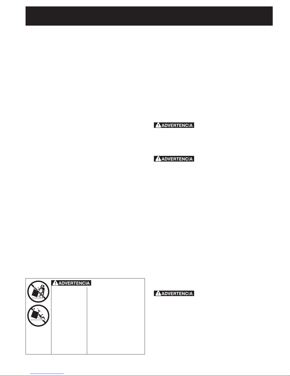
Reducir el riesgo de
• Todas las
estufas pueden
volcarse.
• Esto podría
resultar en
lesiones
personales.
• Instale el
dispositivos
antivuelco que
se ha empacado
junto con esta
estufa.
que se vuelque la estufa,
hay que asegurarla
adecuadamente colocandole
los soportes antivuelco
que se proporcionan. Para
comprobar si estos están
instalados y apretados en
su lugar como se debe, ase
el borde trasero superior de
la estufa y cuidadosamente
inclínela hacia adelante para
asegurar que la estufa se
ancle.
Standard, title 24 CFR part 3280". (Anteriormente
"The Federal Standard for Mobile Home Construction
and Safety title 24, HUD (Part 280)". O cuando estos
estandares no sean aplicables: "The Standard for
Manufactured Home Installation 1982, (Manufactured
Home Sites, Communities and set-ups), ANSI Z225.1,
última edición o códigos y regulaciones locales.
• Asegúrese de que el material que recubre las
paredes alrededor de la estufa, pueda resistir
el calor generado por la estufa.
• No obstruya el ujo del aire de combustión en
la ventilación del horno ni tampoco alrededor
de la base o debajo del panel inferior
delantero de la estufa. Evite tocar las aberturas
o áreas cercanas de la ventilación, ya que pueden
estar muy calientes durante el funcionamiento
del horno. La estufa requiere aire fresco para la
combustión apropiada de los quemadores.
Nunca deje niños solos o
desatendidos en un área donde un artefacto
está siendo usado. A medida que los niños crecen,
enséñeles el uso apropiado y de seguridad para todos
los artefactos. Nunca deje la puerta del horno abierta
cuando la estufa está desatendida.
No se pare, apoye o siente en
las puertas o cajones de esta estufa pues puede
resultar en serias lesiones y puede también causar
daño a la estufa.
• No almacene artículos que puedan interesar
a los niños en los gabinetes sobre la estufa.
Los niños pueden quemarse seriamente tratando de
trepar a la estufa para alcanzar estos artículos.
• Los gabinetes de almacenamiento sobre la estufa
deben ser evitados, para eliminar la necesidad de
tener que pasar sobre los quemadores superiores
de la estufa para llegar a ellos.
• Ajuste el tamaño de la llama de los
quemadores superiores de tal manera que
ésta no sobrepase el borde de los utensilios de
cocinar. La llama excesiva es peligrosa.
• No use el horno como espacio de almacenaje.
Esto creará una situación potencialmente peligrosa.
• Nunca use la estufa para calentar el cuarto.
El uso prolongado de la estufa sin la adecuada
ventilación puede resultar peligroso.
• No almacene ni utilice gasolina u otros vapores
y líquidos inamables en la proximidad de éste
o de cualquier otro artefacto eléctrico. Puede
provocar incendio o explosión.
No trate de usar el horno de
encendido eléctrico durante un corte de energía.
El reestablecimiento del servicio eléctrico cuando los
controles de TEMP DEL HORNO y de REGULACIÓN
DEL HORNO están en cualquier posición diferente
a APAGADO causaría el encendido automático del
quemador del horno o del quemador de la parrilla.
Durante un corte de energía eléctrica se pueden
encender los quemadores de la cubierta con una
cerilla. Acerque una cerilla encendida al quemador
9
Page 10
INSTRUCCIONES DE INSTALACIÓN PARA LA ESTUFA A GAS DE 36"
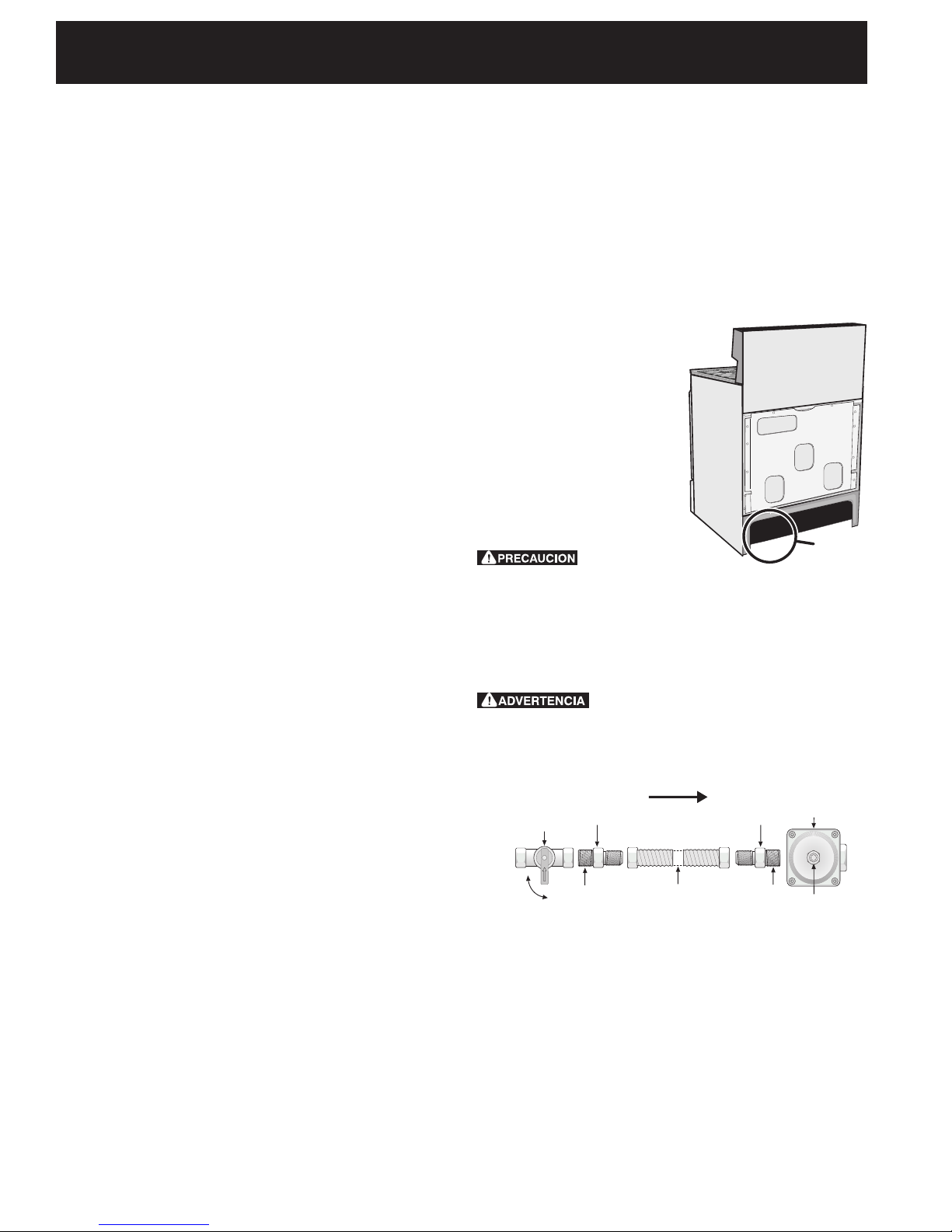
Unión
FLUJO DEL GAS
Valvula de
cierre
manual
Regulador
de presión
Abierto
(On)
Apagado
(Off)
Conector
flexible
Tapa de
entrada
Boquilla Boquilla
Unión
y luego gire lentamente el botón a la posición
ENCENDIDO (LITE). Tenga extremo cuidado al
encender los quemadores en esta forma.
• En caso de una interrupción del servicio eléctrico, es
posible de encender los quemadores de supercie
a mano. Para encender un quemador de supercie,
acerque un fósforo encendido del cabezal del
quemador, y gire delicadamente el botón de control
de supercie a LITE (encendido). Tener cuidado al
encender los quemadores a mano.
• Ajuste todos los controles a la posición "OFF"
(apagada) después de haber hecho una
operación.
PARA MODELOS AUTOLIMPIANTES:
• Saque la asadera, alimentos o cualquier
otro utensilio antes de usar el ciclo de auto
limpieza del horno. Limpie todo exceso de
derrame de alimentos. Siga las instrucciones de pre
limpiado en el Manual del Usuario.
• A diferencia de la gama estándar cocinas
de gas, ESTA PLANCHA DE COCINA NO ES
MOVIBLE. No intente quitar la plancha de cocina.
1. Antes de instalar la estufa a gas
Remueva todos los articulos de embalaje
Retire toda la cinta, todos los artículos de embalaje y de
expedición, y el embalaje de la rejilla del horno. Levante
la plancha para cocinar y remueva los dos tornillos de
expedición de los quemadores de la plancha para cocinar.
Un examen de detección de fugas del aparato debe ser
realizado según las instrucciones en el paso 4.
La línea de fuente de gas debe ser de ½" o de ¾".
3. Selle las aperturas
Sella todas las aperturas en la pared detrás de la
estufa y en el suelo debajo de la estufa después que la
línea del suministro de gas sea instalada.
4. Conecte la estufa al suministro
de gas
Importante: Quite todo el
material de embalaje y literatura
de la estufa antes de
conectar el gas y la fuente
eléctrica.
Para evitar fugas, aplique
sellador de tuberías en todas
las partes roscadas machos
(exterior) de la tubería.
El regulador se encuentra en
el lugar que se muestra en
la ilustración.
No permita
que el regulador gire
sobre la tubería al
apretar las uniones.
Ubicación del
regulador de
presión
Figure 2
2. Proporcione un suministro de
gas adecuado
Cuándo se envía de la fábrica, Esta unidad ha sido
ajustada para operar con un múltiple de admisión para
gas natural de 4" (10.16 cm)(1.0 kPa). Un regulador
de presión convertible esta conectado a la válvula
distribuidora y DEBE ser conectado con la tubería
del suministro de gas. Si el juego de conversión
del propano LP/Propano se ha utilizado, sigue las
instrucciones proporcionadas el juego para convertir el
regulador de presión al uso de LP/Propano.
Se debe de tener cuidado durante la instalación de la
estufa para no obstruir el ujo de aire de combustión y
ventilación
Para la operación apropiadas, la máxima presión de
entrada al regulador no debe exceder la presión de
una columna de agua de 14"(35,56 cm) (3.5 kPa). La
presión de entrada al regulador debe ser por lo menos
1" (.25 kPa) más grande que la válvula distribuidora.
Ejemplos: Si regulador se pone para el gas natural con
una presión de 4"(10,16 cm), la presión de entrada
al regulador debe ser por lo menos 5"(12.60 cm); si
el regulador se ha convertido para gas LP/Propane
10"(25,4 cm) la presión de entrada al regulador debe
ser por lo menos 11"(27,9 cm).
Conecte el Regulador de Presión
El regulador de presión esta ya instalada para la estufa.
No haga la conexión demasiado
apretada. El regulador es de die cast. El apretar
demasiado puede agrietar el regulador dando por
resultado una fuga de gas y un fuego o una explosión.
Todas las conexiones deben ser apretadas con
una llave inglesa- Figura 3
Reúna el conector exible del tubo del suministro de
gas al regulador de la presión en la orden siguiente:
1. Válvula de cierre manual (no incluido)
2. Boquilla de 1/2" (no incluido)
3. 1/2" Adaptador de unión (no incluido)
4. Conector exible (no incluido)
5. 1/2" Adaptador de unión (no incluido)
6. Boquilla de 1/2" (no incluido)
7. regulador de presión (incluido)
10
Page 11
INSTRUCCIONES DE INSTALACIÓN PARA LA ESTUFA A GAS DE 36"
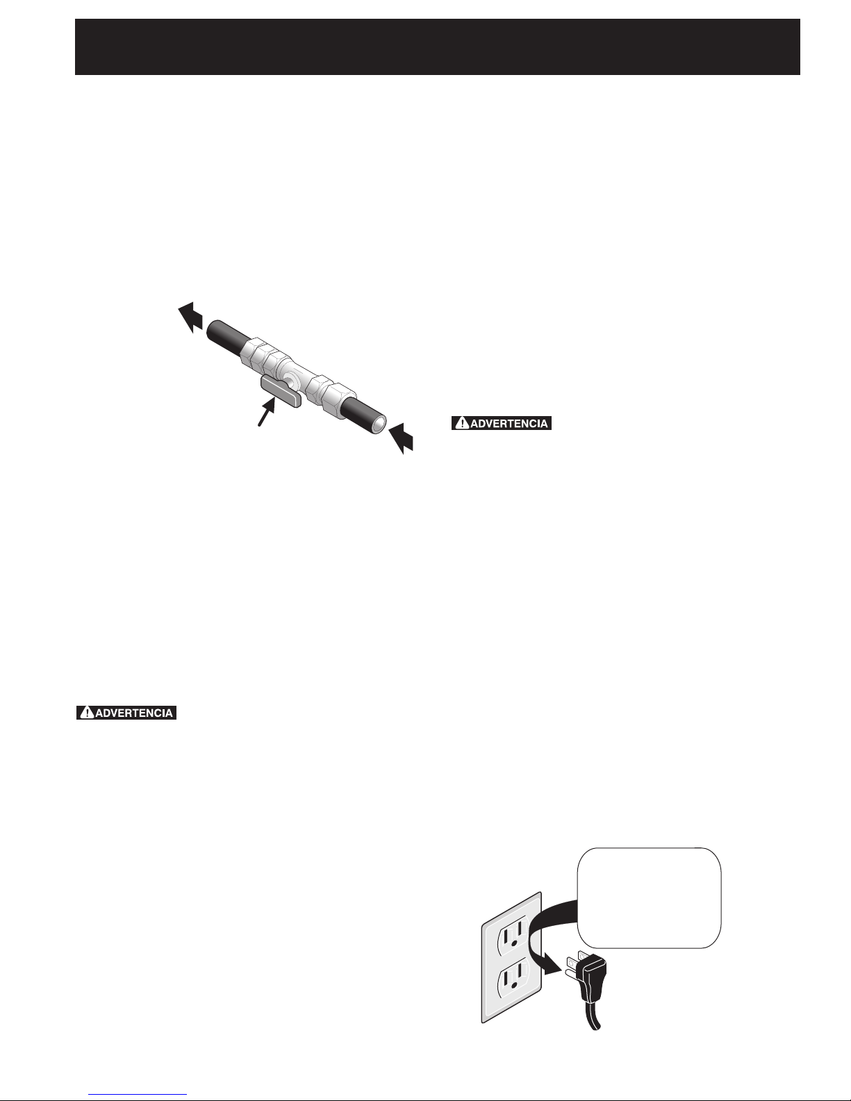
Válvula manual de cierre -
Abierta
Al artefacto
Delinea de gas
Use sellador para uniones de tuberías hecho para el
uso de gas natural y LP/Propano para sellar todas las
conectiones de gas. Si se utilizan los conectadores
exibles, asegúrese de que los conectadores no están
enroscados.
La línea del suministro se debe de ser equipada de
una válvula de cierre manual aprobada. Esta válvula
se debe localizar en el mismo cuarto que la estufa y
debe estar en una localización que permita la facilidad
de la abertura y del cierre. No bloquee el acceso a la
válvula. La válvula es para encender o apagar el gas
del aparato.
Figura 4
5. Conversión para uso de Propano
Líquido
Este aparato puede ser usado con gas natural o
propano líquido. Ha sido ajustado en la fábrica para
operar con gas natural solamente.
Si desea convertir su estufa para uso con propano
líquido, use los oricios provistos ubicados en el bolso
que contiene la literatura titulada "FOR LP/PROPANE
GAS CONVERSION." Siga las instrucciones que vienen
con los oricios.
La conversión debe ser efectuado por un técnico de
servicio capacitado, de acuerdo con las instrucciones
del fabricante y con todos los códigos y requisitos
de las autoridades correspondiente. El no seguir las
instrucciones podría dar como resultado lesiones
graves o daños a la propiedad. El organismo
autorizado para llevar a cabo este trabajo asume la
responsabilidad de la conversión.
La falta de una conversión apropiada
puede resultar en lesiones graves y daños a la
propiedad.
Una vez que regulador está en su lugar, abra la válvula
en la línea del suministro de gas. Espere algunos
minutos para que el gas pueda moverse a través de la
línea de gas.
Compruebe para saber si hay fugas de gas.
Después de conectar la estufa con la fuente de
gas, compruebe el electrodoméstico para saber si
hay fugas con un manómetro. Si un manómetro no
está disponible, gire la fuente de gas y utilice un
detector líquido de fugas (o jabón y agua) en todos
los empalmes y conexiones has la comprobación para
fugas.
No utilice una llama para vericar
fugas en las conexiones de gas. Vericar para fugas
con una llama puede tener como resultado un fuego o
la explosión.
Apriete todas las conexiones como necesario para
prevenir fugas de gas en la supercie de la estufa o en
la linea de suministro.
Desconecte la estufa del sistema de tubería del
suministro de gas durante cualquier prueba de presión
de ese sistema a presiones mayores de ½ psig (3,5
kPa o 14" columna de agua).
Aísle la estufa del sistema de tubería del
suministro de gas cerrando su válvula de cierre
manual durante cualquier prueba de presión del
sistema de tubería del suministro de gas prueba de
presión iguala a o a menos de ½ psig (3,5 kPa o 14"
columna de agua).
6. Requisitos eléctricos
120 voltio, 60 Hertzio, circuito dedicado
apropiadamente puestos a tierra protegido por un
circuito de amperio o fusible de demora de tiempo de
15 amp. Nota: no es recomendado instalarlo con un
Interruptor (GFI) de puesta a tierra.
No utilice una extensión con esta estufa.
Instrucciones de puesta a tierra
IMPORTANTE Por favor lea con cuidado.
Para la seguridad personal, este aparato debe
ser puesto a tierra apropiadamente.
El cable del suministro eléctrico de esta estufa está
equipado con un enchufe de tres patillas (para puesta
a tierra) que coincida con un enchufe de pared
estándar con puesta a tierra de tres patillas para
minimizar la posibilidad que se produzcan descargas
eléctricas.
El cliente deberá encargar a un técnico para
asegurarse de que el enchufe se encuentra
debidamente conectado a tierra y polarizado.
Método preferido
Enchufe de pared
con toma de
tierra
No corte, retire
o derribe,
bajo ninguna
circunstancia, la
patilla de la toma de
tierra del enchufe
Cable de suministro
eléctrico con enchufe
con toma de tierra
Figura 5
11
Page 12
INSTRUCCIONES DE INSTALACIÓN PARA LA ESTUFA A GAS DE 36"
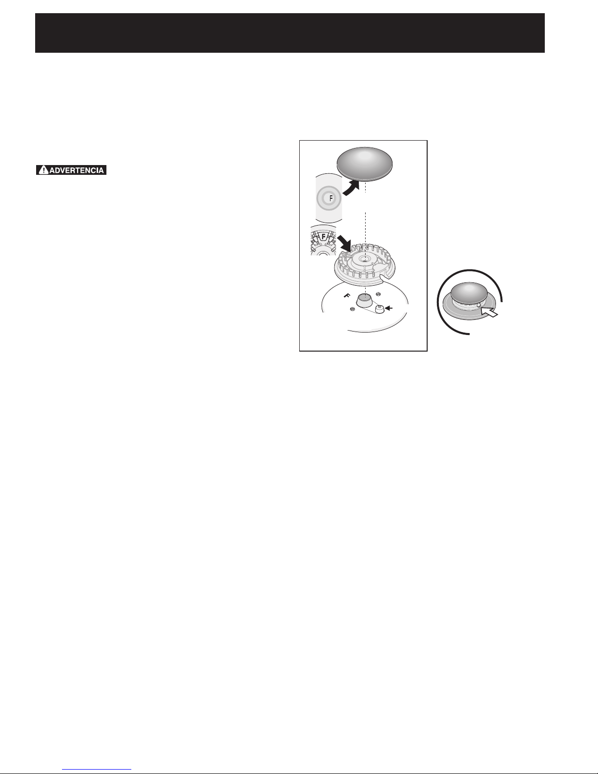
Los
electrodosdeben
estar alineados con la
ranura de cada cabeza
de quemador
Figura 6B
Tapa del
quemador
Cabeza
del
quemador
Electrodo
Deflector del
quemador
Figura 6A
En lugares en los que aya un enchufe de pared
estándar de dos patillas, el cliente tendrá
responsabilidad directa y la obligación de reemplazarlo
por un enchufe de pared de tres patillas debidamente
cableado a tierra.
Bajo ninguna circunstancia, corte, retire o
derribe la tercera patilla (de toma de tierra) del
cable del suministro de energía eléctrica.
Desenchufa el cable del suministro
de energía eléctrica del enchufe de pared antes de
mantener la estufa.
7. La mudanza del aparato para
reparaciones o limpieza
Apague la corriente eléctrica a la estufa a la fuente de
poder principal, y apague la válvula de cierre manual
de gas. Asegúrese de que la estufa esté fresca. Quite
el cajón de servicio (el cajón calentador en algunos
modelos) y abre la puerta del horno. Levante la frente
de la estufa y deslícela fuera de la abertura sin crear
tensión desmedida sobre el conducto exible de gas.
Asegúrese de no pellizque el conducto exible de
gas detrás de la estufa al reemplazar la unidad en
la abertura. Reemplace el cajón, cierre la puerta y
enciende el gas y la corriente eléctrica a la estufa.
8. Comprobación del
funcionamiento
Consulte el Manual del Usuario incluído con la estufa
para instrucciones de operación y instrucciones para el
cuidado y limpieza de su estufa.
No toque los elementos o quemadores. Pueden estar
bastante calientes para causar quemaduras.
Quite todo el embalaje de la unidad antes de
comprobarla.
8.1 Instala las Bases y las tapas de los
Quemadores
Esta estufa esta equipada con
quemadores sellados como mostrado
(vea la Figura 6).
Es muy importante asegurarse de que todas las
cabezas de los quemadores superiores, las tapas de los
quemadores superiores y las rejillas de los quemadores
superiores estén instaladas correctamente y en sus
lugares correctos.
1. Retire toda la cinta de empaque de la cubierta. Retire
las tapas y cabezas de los quemadores (Figura 6A).
2. Descarte todo el material de empaque que se encuentra
debajo de las cabezas de los quemadores.
3. Para volver a instalar las cabezas y tapas de los quemadores, haga concordar las letras ubicadas debajo de las
tapas (en el centro) con las letras que se encuentran
dentro de las cabezas de los quemadores (Figura 6A).
4. Haga concordar las letras estampadas en los deectores
de los quemadores con las de las cabezas y tapas de los
quemadores. Vuelva a colocar las cabezas y tapas de
los quemadores en la cubierta. Alinee cuidadosamente
los electrodos en la ranura o agujero de cada cabeza de
quemador (Figura 6B).
Nota: Las cabezas de
los quemadores deben
quedar planas sobre los
deectores de los quemadores de la cubierta.
5. Desempaque las reji-
llas de los quemadores
y colóquelas sobre la
cubierta.
8.2 Enciende la corriente eléctrica y abre
la válvula principal de cierre.
8.3 Comprobación de los Encendedores
El funcionamiento de los encendedores eléctricos
debe ser comprobado después de que la estufa y los
conectores a la tubería de suministro de gas hayan
sido comprobados para las fugas y la estufa haya
sido conectada eléctricamente. Para comprobar que
el encendido sea correcto:
a. Empuje y gire un botón control del quemador
superior hasta la posición LITE (encender). Se
podría oír el encendedor haciendo chispas.
b. El quemador se deberá encender en cuatro (4)
segundos para un funcionamiento normal, después
de que el aire haya sido purgado de la tubería de
suministro de gas. Controle visualmente que el
quemador se haya encendido.
c. Después de que el quemador se haya encendido,
la plancha de cocina debe ser girada fuera de la
posición LITE. Cada quemador tiene su encendedor
individual. Controle las perillas separadamente
hasta que todas las válvulas hayan sido controladas.
12
Page 13
INSTRUCCIONES DE INSTALACIÓN PARA LA ESTUFA A GAS DE 36"
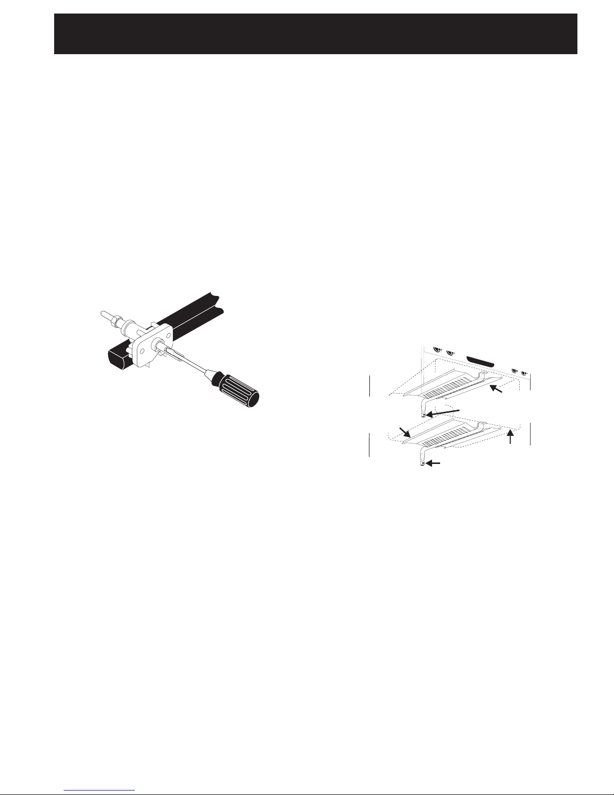
8.4 Ajuste de la Posición LOW (BAJA)
Para la Válvula del Quemador Superior
(Figura 7)
a. Gire el botón de control a la posición LITE
(encender) hasta que el quemador encienda.
b. Rápidamente gire el botón de control a la
POSICIÓN MAS BAJA.
c. Si el quemador se apaga, reajuste la válvula de la
siguiente forma: Mueva el control a la posición OFF
(apagada). Saque la perilla de control del quemador
superior, inserte un destornillador plano pequeño en
el hueco del vástago del a válvula hasta enganchar
el tornillo interior. El tamaño de la llama puede ser
aumentado o disminuido girando el tornillo. Ajuste
el tamaño de la llama hasta que pueda pasar
rápidamente de la posición LITE hasta la posición
MAS BAJA sin que se apague la llama. La llama debe
ser lo más pequeña posible sin que se apague.
desaparecerá por 20 a 30 segundos después de que
el encendedor se apaga. Para mantener cualquier
temperatura de horno dada, este ciclo continuará tanto
como el dial (o visualizador) esté congurado para
operar.
Después de retirar todos los materiales del empaque y la
literatura del horno:
a) Fije el horno en HORNEAR (BAKE) a 300°F. Vea la
guía de Uso y Cuidado para conocer las instrucciones
de funcionamiento.
b) En 60 segundos el quemador del horno se encenderá.
Revise que exista un fuego adecuado (vea 8.5.2), y
permita que el quemador cumpla su ciclo una vez.
Gire los controladores hacia off (APAGADO).
c) Si su modelo esta equipado con un asador central
superior, je el horno en ASAR. Vea la Guía de
Uso y Cuidado para conocer las instrucciones de
funcionamiento.
d) En 60 segundos el quemador de asar debe de
encenderse. Revise si exista una llama adecuada (vea
8.5.3). Gire los controles hacia off (APAGADO).
8.5.2 Obturador del Aire - Quemador del horno
Figura 7
8.5 Operación de Quemadores del Horno
y Ajustes de Horno
8.5.1 Quemador de ignición eléctrica
La operación de los encenderse eléctricos debe de ser
revisada después de que la cocina y los conectores
de la línea de suministro haya sido cuidadosamente
revisada para descartar fugas y que la cocina haya sido
conectada a la corriente eléctrica.
El quemador del horno está equipado con un sistema de
control eléctrico así como un encendedor de quemador
de horno eléctrico. Si su modelo esta equipado con un
quemador de asado central superior, también contará
con un encendedor de quemador eléctrico. Estos
sistemas de control no requieren ajustes. Cuando el
horno esta congurado para operar, la corriente uirá
hacia el encendedor y tendrá un resplandor de manera
similar a una bombilla de luz. Cuando el encendedor a
alcanzado una temperatura suciente para encender el
gas, la válvula del horno controlada eléctricamente se
abrirá y el fuego aparecerá en el quemador del horno.
hay un lapso de tiempo de 30 a 60 segundos después
de que el termostato se enciende y antes de que la
llama aparezca en el quemador del horno. Cuando el
horno alcanza la conguración del dial, el encendedor
resplandeciente se apagará. La llama del quemador
Deector inferior
del horno
(extraíble)
Figura 8
La longitud aproximada de la llama del quemador del
horno es 1 pulgada (interior claro, llama azul). Para
determinar si la llama del quemador de horno es la
adecuada, retire el fondo del horno y el deector del
quemador i je el horno en la opción hornear a 300°F.
Para retirar el fondo del horno, retire los tornillos de
ajuste del horno en la parte posterior del fondo del
horno. jale hacia arriba, desenganche el frente del fondo
del marco anterior del horno, y jale la base hacia a fuera
de éste. retire el deector del quemador de manera que
la llama del quemador pueda ser observada.
Si la llama es de color amarillo, aumente el tamaño de la
abertura del obturador de aire (Vea el tamaño "2" en el
gura 9). Si la llama es de azul claro, reduzca el tamaño
de la abertura del obturador de aire. Para ajustar un
tornillo de cierre ojo (Vea el tamaño "3" en el gura 9),
vuelva a colocar el obturador de aire, y ajuste el tornillo
de cierre. Reemplace el fondo del horno.
Obturador
de aire
Obturador
de aire
Quemador a
la altura de la
cintura
Parte inferior del
horno (extraíble)
13
Page 14

INSTRUCCIONES DE INSTALACIÓN PARA LA ESTUFA A GAS DE 36"
Tubos del
quemador
del horno
Tornillos de
3
seguridad
2
Obturador
de aire
Figura 9
8.5.3 Obturador de aire - Quemador de asado
La longitud aproximada de la llama del quemador de
asado es 1 pulgada (interior claro, llama azul). Para
determinar si la llama del quemador de asado es la
adecuada, poner el horno en la opción asar.
Si la llama es de color amarillo, aumente el tamaño de la
abertura del obturador de aire (Vea el tamaño "2" en el
gura 9). Si la llama es de azul claro, reduzca el tamaño
de la abertura del obturador de aire, y ajuste el tornillo
de cierre (Vea el tamaño "3" en el gura 9).
Tapa del
1
oricio
9. Asegúrese que la estufa esta a
nivel
Nivele la estufa, instalado un nivel horizontalmente sobre
una rejilla del horno. Verique en diagonal de adelante
hacia atrás, y nivele la estufa ajustando las patas de
nivelación o poniendo cuñas por debajo de los ricónes
de la estufa como sea necesario.
Después de Terminar la Instalación
Asegúrese de que todos los controles estén en la posición
OFF (apagada).
Asegúrese de que el uir del aire de combustión y de
ventilación a la estufa no esté obstruido.
Ubicación del Número de Modelo y de
Serie
La placa con el número de serie está ubicada en el
marco delantero del horno detrás de la puerta del horno
(algunos modelos) o detrás del cajón (algunos modelos).
Cuando haga pedidos de repuestos o solicite información
con respecto a su estufa, esté siempre seguro de incluir
el número de modelo y de serie y el número o letra del
lote de la placa de serie de su estufa.
La placa con el número de serie también le da la potencia
nominal de los quemadores, el tipo de combustible y la
presión a la cual fue ajustada la estufa en la fábrica.
Antes de llamar al servicio
Lea la sección Lista de Control de Averías en su
Manual del Usuario. Esto le podrá ahorrar tiempo y
gastos. Esta lista incluye ocurrencias comunes que
no son el resultado de defectos de materiales o
fabricación de este artefacto.
Lea la garantía y la información sobre el servicio en
su Manual del Usuario para obtener el número de
teléfono y la dirección del servicio. Por favor llame
o escriba si tiene preguntas acerca de su estufa o
necesita repuestos.
14
Page 15
INSTRUCCIONES DE INSTALACIÓN PARA LA ESTUFA A GAS DE 36"
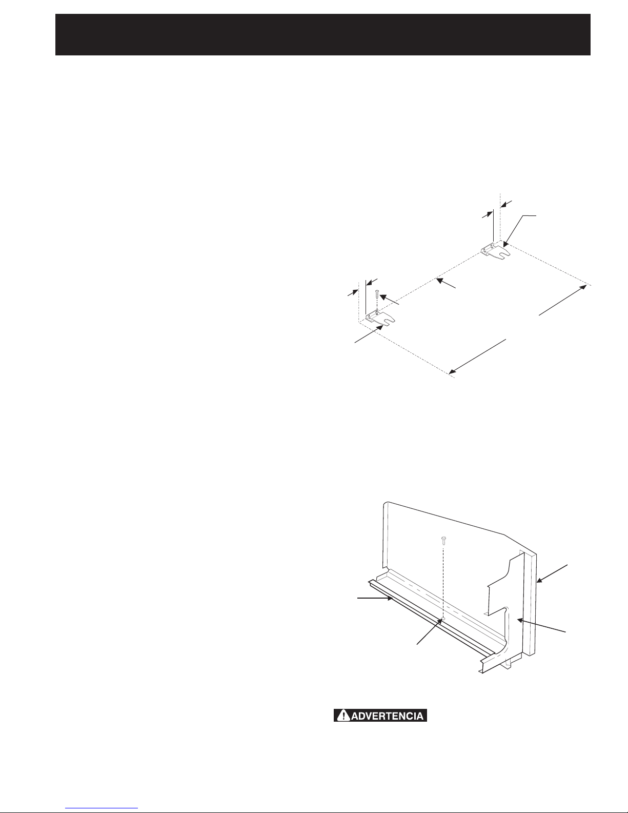
10. Instrucciones para de
instalación del soporte antivuelco
Advertencia de seguridad importante
Esta estufa debe ser asegurada al piso usando las
platinas de anclaje y los tornillos suministrados. El
no instalar apropiadamente los soportes antivuelco
puede llegar a permitir que la estufa se incline hacia
adelante, accidentalmente, si se coloca un peso
excesivo sobre la puerta abierta o si un niño se sube
en ella. La estufa caliente a los liquidos calientes
derramados podrían causar serias lesiones personales.
Reérase a las instrucciones que se dan a continuación
para la correcta instalación de los soportes antivuelco
(Figura 10).
NOTA: Si mueva la estufa a otro sitio, deba también
mover los soportes antivuelco para instalarlas
con la estufa.
Las piezas se encuentran en un saco de plástico
en el horno.
Herramientas requeridas:
Llave de tuerca de 5/16” o destornillador de cabeza
plana
Llave ajustable
Broca para mampostería de 3/16” de diámetro (para
taladrar concreto)
5. Deslice la estufa hasta que quede en su lugar
asegurándose de que las patas traseras están
atrapadas bajo las platinas de anclaje. Puede
ser necesario balancear la estufa hacia los lados
a medida que se desliza hacia atrás para lograr
que las platas traseras se alineen con las platinas
de anclaje. Para asegurarse de que la estufa
está correctamente anclada remueva el cajón de
almacenamiento o el panel inferior, también puede
vericarse la instalación tratando, cuidadosamente,
de inclinar la estufa hacia adelante.
3
/8"
2 Tornillos
por platina
Instalar
platinas
de anclaje
Borde posterior de la
estufa o pared posterior
Figura 10
Ubicación de los paneles
3
/8"
Instalar
platinas
de anclaje
laterales de la estufa
Asegure las platinas al piso en la parte posterior
de la estufa de forma que soporten las dos platas
niveladoras traseras. Al colocarlas asegúrese de no
perforar alambres eléctricos o tubería. Los tornillos
suministrados pueden usarse en concreto o madera.
La estufa puede anclarse al piso en una residencia con
las platinas de anclaje, tal como se ilustra en la gura
10. Estas platinas permiten que la estufa se hale hacia
adelante para su limpieza o reparación, sin necesidad
de usar herramientas.
1. Asegure las platinas de anclaje al piso o a la
pared poste rior con los tornillos suministrados.
Importante: las platinas deben anclarse sobre
madera o piso sólido. No deben anclarse sobre
estuco, chapa de roca o algún otro material de baja
resistencia. Si el anclaje va a hacerse sobre la pared
posterior, deben removerse todas la molduras que
queden detrás de la estufa.
2. Si las platinas van a anclarse en pisos de
manpostería o cerámica, coloque las platinas en el
piso y marque la ubicación de los oricios. Taladre
oricios de
3/16”.
3. Gire las patas niveladoras 3 vueltas hacia abajo de
forma que las platinas deslicen sobre las cabezas
niveladoras.
4. Nivele la parte delantera y trasera de la estufa y
las partes laterales con los dos niveladores de pata
delanteros y los niveladores traseros.
En casas móviles la estufa debe anclarse al piso come
se muestra en la gura 11.
1. Remueva el panel falso o el cajón de
almacenamiento para poder alcanzar los oricios de
anclaje.
2. En el centro de cada riel de la base de la estufa se
suministra un oricio de ¼” para el anclaje al piso.
lateral del
Riel
de la base
Armazón
Oricio para anclar la estufa al piso oricio ubicado
aproximadamente en la mitad
del riel
puerta o cajón de esta estufa causar serias lesiones personales y también puede dañar la estufa.
15
Figura 11
Pararse, apoyarse o sentarse en la
frontal
Parte
cuerpo
Page 16
WIRING DIAGRAM - DIAGRAMA DE LA INSTALACIÓN ALÁMBRICA
 Loading...