

Frigidaire Fully Integrated Direct FeedModel Dishwashers, PLD4555RFC, PLD4375RFC, LEDB500FEE Service Manual
Dishwasher
Service Manual
Fully Integrated Direct Feed
Model Dishwashers
5995477345 October 2006

SAFE SERVICING PRACTICES - ALL APPLIANCES
To avoid personal injury and/or property damage, it is important that Safe
Servicing Practices be observed. The following are some limited examples of
safe practices:
1. DO NOT attempt a product repair if you have any doubts as to your ability to
complete it in a safe and satisfactory manner.
2. Before servicing or moving an appliance:
• Remove the power cord from the electrical outlet, trip the circuit breaker to
the OFF position, or remove the fuse.
• Turn off the gas supply.
• Turn off the water supply.
3. Never interfere with the proper operation of any safety device.
4. USE ONLY REPLACEMENT PARTS CATALOGED FOR THIS APPLIANCE.
SUBSTITUTIONS MAY DEFEAT COMPLIANCE WITH SAFETY
STANDARDS SET FOR HOME APPLIANCES.
5. GROUNDING: The standard color coding for safety ground wires is GREEN,
or GREEN with YELLOW STRIPES. Ground leads are not to be used as current
carrying conductors. It is EXTREMELY important that the service technician
reestablish all safety grounds prior to completion of service. Failure to do so
will create a hazard.
6. Prior to returning the product to service, ensure that:
• All electrical connections are correct and secure
• All electrical leads are properly dressed and secured away from sharp
edges, high-temperature components, and moving parts
• All non-insulated electrical terminals, connectors, heaters, etc. are
adequately spaced away from all metal parts and panels
• All safety grounds (both internal and external) are correctly and securely
connected
• All panels are properly and securely reassembled
ATTENTION!!!
This service manual is intended for use by persons having electrical and mechnical
training and a level of knowledge of these subjects generally considered acceptable in the
appliance repair trade. Electrolux Home Products, Inc. cannot be responsible, nor assume
any liability, for injury or damage of any kind arising from the use of this manual.
© 2006 Electrolux Home Products, Inc.
2

TABLE OF CONTENTS
Safe Servicing Practices ------------------------------------------------------------------------------------------- 2
The Design and Operation of the Fully Integrated Dishwasher --------------------------------------- 5
PLD4555RFC ----------------------------------------------------------------------------------------------------- 5
PLD4375RFC ----------------------------------------------------------------------------------------------------- 5
LEDB500FEE ----------------------------------------------------------------------------------------------------- 5
Cycle Selections ------------------------------------------------------------------------------------------------------ 6
Ulimate Scrub---------------------------------------------------------------------------------------------------- 6
Maxx Clean ------------------------------------------------------------------------------------------------------- 6
Speed Clean ------------------------------------------------------------------------------------------------------ 6
Normal Wash----------------------------------------------------------------------------------------------------- 6
China/Crystal ---------------------------------------------------------------------------------------------------- 6
Eco Wash --------------------------------------------------------------------------------------------------------- 6
Top Rack, Glasses and Party Glasses ------------------------------------------------------------------- 6
Rinse Only -------------------------------------------------------------------------------------------------------- 6
Favorite Cycle --------------------------------------------------------------------------------------------------- 6
Option Selections ---------------------------------------------------------------------------------------------------- 7
Wash Pressure -------------------------------------------------------------------------------------------------- 7
Wash Temperature --------------------------------------------------------------------------------------------- 7
Sanitize Rinse --------------------------------------------------------------------------------------------------- 7
Dry------------------------------------------------------------------------------------------------------------------- 7
Delay Start -------------------------------------------------------------------------------------------------------- 7
Control Lock ----------------------------------------------------------------------------------------------------- 8
Digital Display --------------------------------------------------------------------------------------------------- 8
Status Indicators ----------------------------------------------------------------------------------------------------- 8
WASHING --------------------------------------------------------------------------------------------------------- 8
DRYING ------------------------------------------------------------------------------------------------------------ 8
CLEAN ------------------------------------------------------------------------------------------------------------- 8
SANITIZE ---------------------------------------------------------------------------------------------------------- 8
Rinse Agent LOW ----------------------------------------------------------------------------------------------- 8
Wash System ----------------------------------------------------------------------------------------------------------- 8
The Alternating Wash System -------------------------------------------------------------------------------------- 9
Part in the Wash System--------------------------------------------------------------------------------------------- 10
Wash Pump ------------------------------------------------------------------------------------------------------- 10
Stainless Steel Filter --------------------------------------------------------------------------------------------- 10
Lower Spray Arm ------------------------------------------------------------------------------------------------- 11
Center Spray Arm ------------------------------------------------------------------------------------------------ 11
Upper Spray Arm ------------------------------------------------------------------------------------------------- 11
Drain Pump -------------------------------------------------------------------------------------------------------- 11
Drying System ---------------------------------------------------------------------------------------------------------- 12
Fan/Vent Assembly ---------------------------------------------------------------------------------------------- 12
Heater--------------------------------------------------------------------------------------------------------------- 13
Door Baffles ------------------------------------------------------------------------------------------------------- 13
Dispensing System ---------------------------------------------------------------------------------------------------- 13
Dispenser Operation -------------------------------------------------------------------------------------------- 13
Door Latch Assembly ------------------------------------------------------------------------------------------------- 14
Fill System --------------------------------------------------------------------------------------------------------------- 14
Door Hinge and Spring ----------------------------------------------------------------------------------------------- 14
3

The Control System --------------------------------------------------------------------------------------------------- 15
Soil Sensing ------------------------------------------------------------------------------------------------------- 15
Temperature Controls ------------------------------------------------------------------------------------------- 15
Service Tests ------------------------------------------------------------------------------------------------------ 16
Water Temperature Test ----------------------------------------------------------------------------------- 16
To Activate the Water Temperature Test --------------------------------------------------------- 16
Water/Service Test------------------------------------------------------------------------------------------ 16
To Start the Test ---------------------------------------------------------------------------------------- 16
To Exit the Water/Service Test --------------------------------------------------------------------- 16
Chart for the Water/Service Test ------------------------------------------------------------------- 17
Relay/Triac and Sensor Test ----------------------------------------------------------------------------- 17-18
Control Codes----------------------------------------------------------------------------------------------------- 19
Disassembly and Service -------------------------------------------------------------------------------------------- 20
Safety Precautions ----------------------------------------------------------------------------------------------- 20
Control Panel------------------------------------------------------------------------------------------------------ 20
Electronic Control ------------------------------------------------------------------------------------------- 20
Display --------------------------------------------------------------------------------------------------------- 20
Door Latch --------------------------------------------------------------------------------------------------------- 21
Door Strike --------------------------------------------------------------------------------------------------------- 21
Detergent/Rinse Aid Dispenser ------------------------------------------------------------------------------- 21
Door Hinge--------------------------------------------------------------------------------------------------------- 21
Door Seal ---------------------------------------------------------------------------------------------------------- 22
Bottom Door Seal ------------------------------------------------------------------------------------------- 22
Upper Rack -------------------------------------------------------------------------------------------------------- 22
Tub Roller Assembly -------------------------------------------------------------------------------------------- 22
Center Spray Arm ------------------------------------------------------------------------------------------------ 22
Upper Spray Arm ------------------------------------------------------------------------------------------------- 22
Lower Spray Arm, Spray Arm Support and Filter --------------------------------------------------------- 23
Heating Element-------------------------------------------------------------------------------------------------- 23
Float Switch and Mount Bracket ------------------------------------------------------------------------------ 23
Water Valve -------------------------------------------------------------------------------------------------------- 23
Drain Pump -------------------------------------------------------------------------------------------------------- 24
Replacing the Drain Pump -------------------------------------------------------------------------------- 24
Pump and Motor Assembly ------------------------------------------------------------------------------------ 24
Remove motor from sump -------------------------------------------------------------------------------- 24
Delivery Tube ----------------------------------------------------------------------------------------------------- 25
Vent and Fan Assembly ---------------------------------------------------------------------------------------- 25
Exploded Views -------------------------------------------------------------------------------------------------------- 26-34
Control Panel------------------------------------------------------------------------------------------------------ 26
Door - model LEDB500FEE0 --------------------------------------------------------------------------------- 27
Door - models PLD4375RFC0 & PLD4555RFC0 -------------------------------------------------------- 28
Tub ------------------------------------------------------------------------------------------------------------- 29
Motor & Pump ---------------------------------------------------------------------------------------------------- 30
Frame ------------------------------------------------------------------------------------------------------------- 31
Racks - model LEDB500FEE0-------------------------------------------------------------------------------- 32
Racks - model PLD4375RFC0 ------------------------------------------------------------------------------- 33
Racks - model PLD4555RFC0 ------------------------------------------------------------------------------- 34
Service Data Sheet ---------------------------------------------------------------------------------------------------- 35-36
4
Fully Integraded Direct Feed
Model Dishwashers
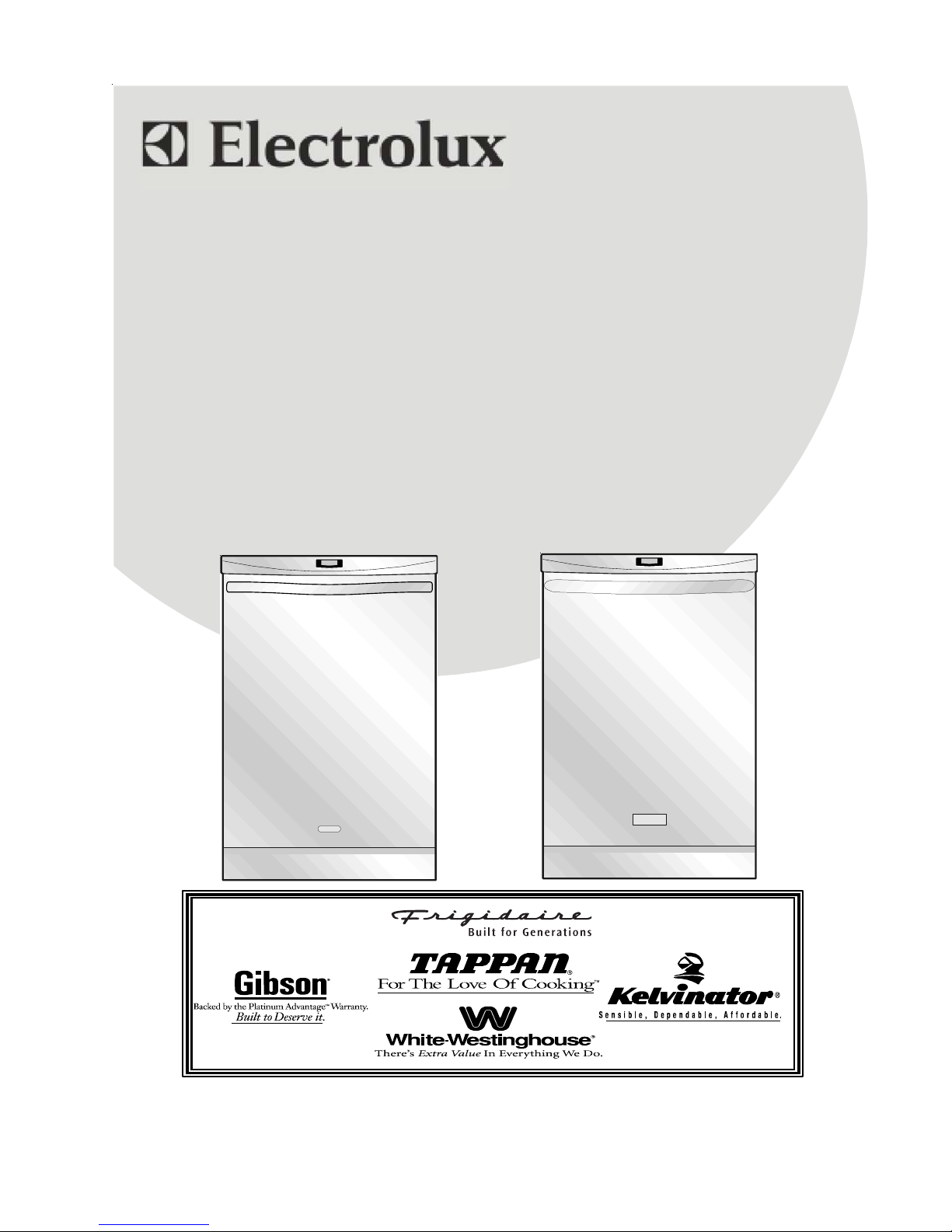
PLD4555RFC
Figure 1
The Design and Operation of the
Fully Intergraded Dishwasher.
The fully integrated control places all cycle selection
and options on top of the console out of sight with
the door closed. With the controls under the counter
top while in operation, the cycle selection needs to
be accomplished with the door opened. First select
a wash cycle and any options, then press the Start/
Cancel pad or a Delayed Start pad and close the
door the cycle begins. A display mounted in the front
of the console shows the time remaining of the delay
or the time remaining in the cycle. While in operation,
the dishwasher control monitors the progress of the
cycle to determined if changes need to be made to
improve the cycle performance. Changes to the
cycle can start as early as the first fill, if food soils in
the water deems it necessary. If the user wishes to
make a change to the cycle, it needs to be done
before the completion of the first fill. After that time
any changes to a wash cycle will require a Cancel/
Drain before a new wash cycle can be selected.
While in operation, the control monitors all aspects of
the cycle with the use of sensors mounted in the
sump. These sensors enable the control to adjust
the length of the cycle based on soil level and water
temperature and are made as needed.
As stated earlier, a wash cycle can not be changed
after the first fill without a Cancel/Drain, options to
the wash cycle can be changed at any time up to
the point they are to be applied. If at any time after
the cycle has been started, the door is opened the
unit will stop, by closing the door the operations will
resume without pressing the Start/Cancel pad. If a
cycle needs to be terminated after the first fill has
started touching the Start/Cancel pad once sends
the unit into a Cancel/Drain for 90 seconds, this
terminates this selection. If while in a Cancel/Drain
the Start/Cancel pad is pressed a second time the
drain action stops immediately. At the completion of
a wash cycle the control lights the Clean indicator;
this indicator remains on until the door is opened.
After the wash cycle is completed and the door
opened when the Start/Cancel pad is pressed for a
new load the control will repeat the previous run
cycle, including all of the previously selected
options.
Added to the fully integrated control, the new design
offers, a new control console which is decreased in
height. The vent and door latch release handle that
had added to the height have been redesigned. The
towel bar handle once decoration now becomes the
door opening handle.
PLD4555RFC This is a 5 speed Professional
model with 6 wash cycles and a Rinse only cycle.
This model has preprogrammed wash pressure,
water temperatures, and dry options for each of the 6
different wash cycles. The user has the option to
change these setting to accommodate their desires.
See Figure 1
PLD4375RFC This is a 3 speed Professional
model with 6 wash cycles and a Rinse only cycle.
This model has preprogrammed wash pressure,
water temperatures, and dry options for each of the
6 different wash cycles.
LEDB500FEE This is a 5 speed Elements model
with 5 wash cycles, a Favorite cycle, and a Rinse
only cycle. This model has preprogrammed settings
for motor speed , water temperature and dry for each
of the wash cycles with the option to change these if
the user wishes. The Favorite Cycle selection allows
the user to program a wash cycle with any options to
their liking, then hold this cycle in memory by press-
ing one pad the designed cycle is repeated.
5
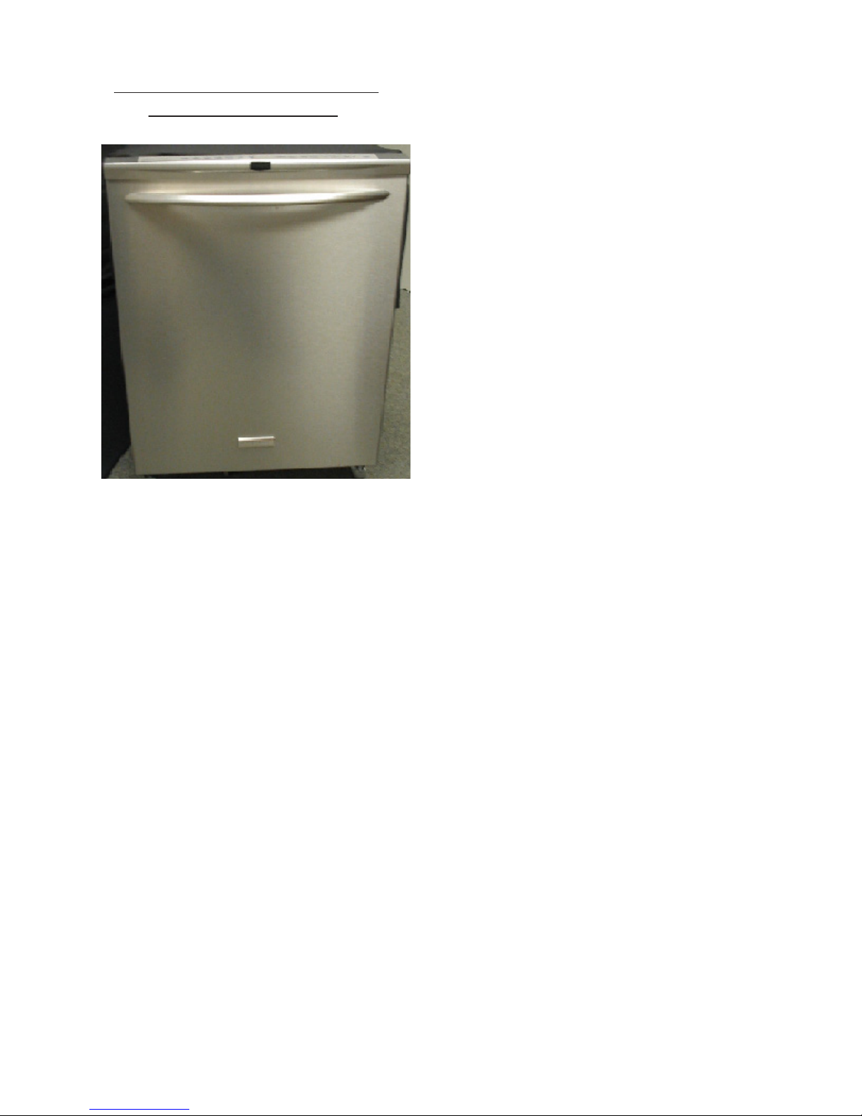
Cycle Selections
PLD4555RFC
PLD4375RFC
Normal Wash
This cycle is for normally soiled dishes. The control
automatically selects the Normal speed for the wash
motor, an assured water temperature of 135°in the
main wash and 140° in the final rinse. All of the
options are available and soil sensing will be used.
China/Crystal
This cycle is for delicate crystal or china. The control
automatically selects the Delicate speed for the wash
motor, an assured water temperature of 130°in both
the main wash and the final rinse. Only the Air Dry
and the Delay Start options are available. Soil
sensing will not be used.
LEDB500FEE
Figure 2
To better understand these different wash cycles the
following are each cycle, the settings and what
options are available.
Ultimate Scrub
This cycle is used for heavily soiled dishes. The
control automatically selects the High speed for the
wash motor, an assured water temperature of 140°in
the main wash and 155° in the final rinse, and dry is
a default to Sahara. All of the options are available
and soil sensing will be used.
Maxx Clean
This cycle is used for heavily soiled dishes. The
control automatically selects the Maxx wash speed
for the wash motor, an assured water temperature of
140°in the main wash, 155° in the final rinse, and dry
is default to Maxx. All of the options are available
and soil sensing will be used.
Eco Wash
This cycle is for lightly soiled dishes The control
automatically selects the Normal speed for the wash
motor, an assured water temperature of 135°in the
main wash and 140° in the final rinse. All Wash
Pressures, Dry Options, and Delay Start options are
available. The Wash Temperature option is not
available and soil sensing will not be used.
Top Rack, Glasses, or Party Glasses
This cycle is used for small loads of glassware or
cups. The control automatically selects the Normal
speed for the wash motor only an assured water
temperature of 135° is set for the final rinse. The
water temperature options, dry options, and Delay
Start are available. Soil sensing will not be used.
Rinse Only
This cycle is intended to rinse dishes that will be
washed at a later time. There are no options
availably with the exception of a Delay Start.
Favorite Cycle
Speed Clean
This cycle is used for a small dish load or lightly
soiled. The control automatically selects a High /
Maxx wash speed on the wash motor, an assured
water temperature of 125° in the main wash and
128° in the finial rinse. Only the Dry Option and
Delay Start options are available. Soil sensing is
used.
This is a cycle programmed by the user and gives
them a short cut to a cycle they use frequently. To
program the Favorite Cycle make the selection of a
wash cycle and all of the desired options, press and
hold the Favorite Cycle pad for three seconds.
Once the Favorite Cycle has been set the following
indicators will flash Time remaining, Favorite Cycle,
the user’s selected cycle and all options selected.
These lights will flash for 2 seconds. The Favorite
cycle can now be set as a wash cycle with the Start/
Cancel pad.
6
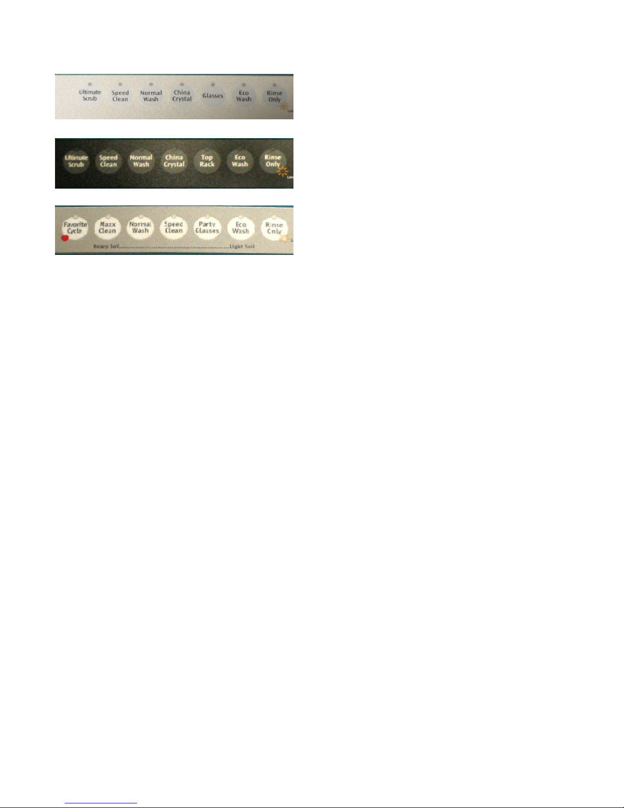
Option Selections
The display will flash an HO on models so equipped.
This option will increase the water temperature to
140°. There is a time override for this option of not
more then 10 minute.
PLD4555RFC
PLD4375RFC
LEDB500FEE
Figure 3
Option selections allow the user flexibility to alter a
wash cycle to their desires. These options are the
speed of the wash motor this will increase water
pressure sprayed on the load, the temperature of
water in both the main wash and finial rinse segment of a cycle, the dry can be a no heat dry or on
some models the heated dry can actually be
extended for a longer time. This section cover
these and a delay start option.
Wash Pressure
This option allows the user to raise or lower the
speed of the wash motor which increases or decreases the pressure of the water used to clean the
dishes. The control will not allow this change in all
cycles because of the intent of the cycle. This
change in water pressure will effect all of the washes
and rinses in this selected cycle.
Sanitize Rinse
The Sanitize rinse increases the finial rinse segment
to a temperature of 155° on select wash cycles. On
models PLD4555RFC and LRDB500FEE when the
sanitize rinse option is selected this selects the High
Temp wash as well, for that reason, both the Sanitize
and Hi temp wash indicators will light. On other
models, this is a separate option. There can be up to
30 minutes delay for the Sanitize rinse when selected. On models with a display, an HO will flash
during this delay period. Once the wash cycle is
completed, the Sanitize light and the Clean light are
light and remain on until the door is opened. If the
155° was not reached in the allotted time, the
Sanitize light will not come on informing the user the
criteria for this setting was not met.
Dry
This option, on all models, can disable the heating
element which gives only an air dry. There is an
active vent and fan assembly located in the top right
back corner of the tub that will be activated at the
end of all wash cycles. On select models, the Dry
option also offers a Max or a Sahara dry, this setting
lengths the dry cycle by 20 minutes to insure a dry
load. If when the dishwasher is in the dry cycle the
door is opened and stays open for more then one
minute the remainder of the dry cycle will cancel out.
Delay Start
Depending on model, the option could read either
“High” or “Maxx” speed. This selection will
substitute the speed of the motor to 3400 rpm when
spraying from the lower spray arm and 3200 rpm
from the upper and center arms. This overrides the
variable speed function of the selected cycle.
Delicate Pressure limits all wash and rinse speeds
to 2800 rpm only for the selected cycle.
Wash Temperature
This option allows for the selection of a high temperature wash in select cycles. The high temperature wash occurs at the end of the main wash
segment of the cycle.
This option allows for a wash cycle to be pro-
grammed into the control and the start delayed for a
set number of hours. A cycle can be delayed from 1
to 24 hours in 1 hour increments. To set a Delay
Start a wash cycle with options is selected followed
by pressing the Delay Start pad. Each time the Delay
Start pad is pressed in 3 second intervals the number
of hours to delay will increase by one hour up to 24
hours. Once the delay begins, time is decreased in
one hour segments until one hour remains, then the
count down changes to minutes. After the count
down starts pressing the Start/Cancel pad will have
no effect on the delay start, if the Start/Cancel pad is
a second time in succession this will cancel the delay
and start the selected cycle.
7
Control Lock
The control lock disables the keypad so that the
settings entered into the control can not be changed.
To activate the control lock press and hold the Delay
Start pad for 3 seconds with the dishwasher door
closed. The Control Lock indicator will illuminate
when the lock is set. To remove the control lock
press and hold the Delay Start pad for 3 seconds
until the light goes out. If the control lock is used, it
should be turned off after the cycle is completed and
before the door is opened.
If the control lock was used and not turned off before
the dishwasher door is opened the light will go out
with the control still locked, resulting in a non functioning dishwasher. This can be corrected by
removing power from the unit this will reset the
control.
Digital Display
The digital display is to indicate the current status of
the cycle. The display is a two digit display so time
will read from 1 to 99 minutes. If a cycle length is
over 99 minutes, the display will have a plus sign (+)
to the right of the numbers. This plus sign (+) will
stay light until the cycle time drops below 99 minutes. The display may also have codes appear to
indicate the status of the cycle or the condition of the
dishwasher. The most common of these codes is an
HO code which may appear and flash in the display,
this indicates that the control has delayed the cycle
to increase the water temperature. Another of these
codes is a flashing CL indicates of an open door.
This code can appear if the control is programmed
and the Start/Cancel pad is pressed before the door
is closed. Close the door and the cycle will start.
The last of the common codes is a PF code. This
will flash in the display on initial power up of the
dishwasher or any time power to the dishwasher has
been interrupted. There are fault codes that can
appear in the display as well; these will be listed as
failure codes in the control test section of this
manual.
The CLEAN indicator is energized at the end of all
wash cycles with the exception of a Rinse and hold
cycle. The clean indicator will remain on until the
door is opened. After the door is open, ALL indicators
will be extinguished with the exception of the “Rinse
aid low” if applicable.
The SANITIZE indicator is shown in the front display
as an “S” and will be energized at the end of any
cycle that the Santi option has been selected. The
sanitize criteria must be completed correctly for this
indicator to come on. This indicator will be extin-
guished when the door is opened.
The Rinse Agent LOW indicator on the keypad will
be on any time the rinse aid level in the dispenser is
low. This light will stay on until the dispenser is filled.
The indicator can also be extinguished after 5
successive cycles have been run with out filling the
dispenser. On select models an Lo will appear in the
front display to indicate the rinse aid dispenser is low
on agent.
Wash System
The wash system consists of wash pump and motor
assembly to provide water under pressure for the
three spray arms used to clean the dishes. These
three spray arms will alternate operation starting with
the lower spray arm. After a predetermined time the
spray will change to the center and upper spray arms
simultaneously.
Status Indicators
The WASHING indicator is energized at the begin-
ning of any wash cycle and will remain on as long as
the vent actuator is not energized.
The DRYING indicator is energized when the vent
actuator is energized and remains on until the end of
the cycle regardless of which drying option is se-
lected.
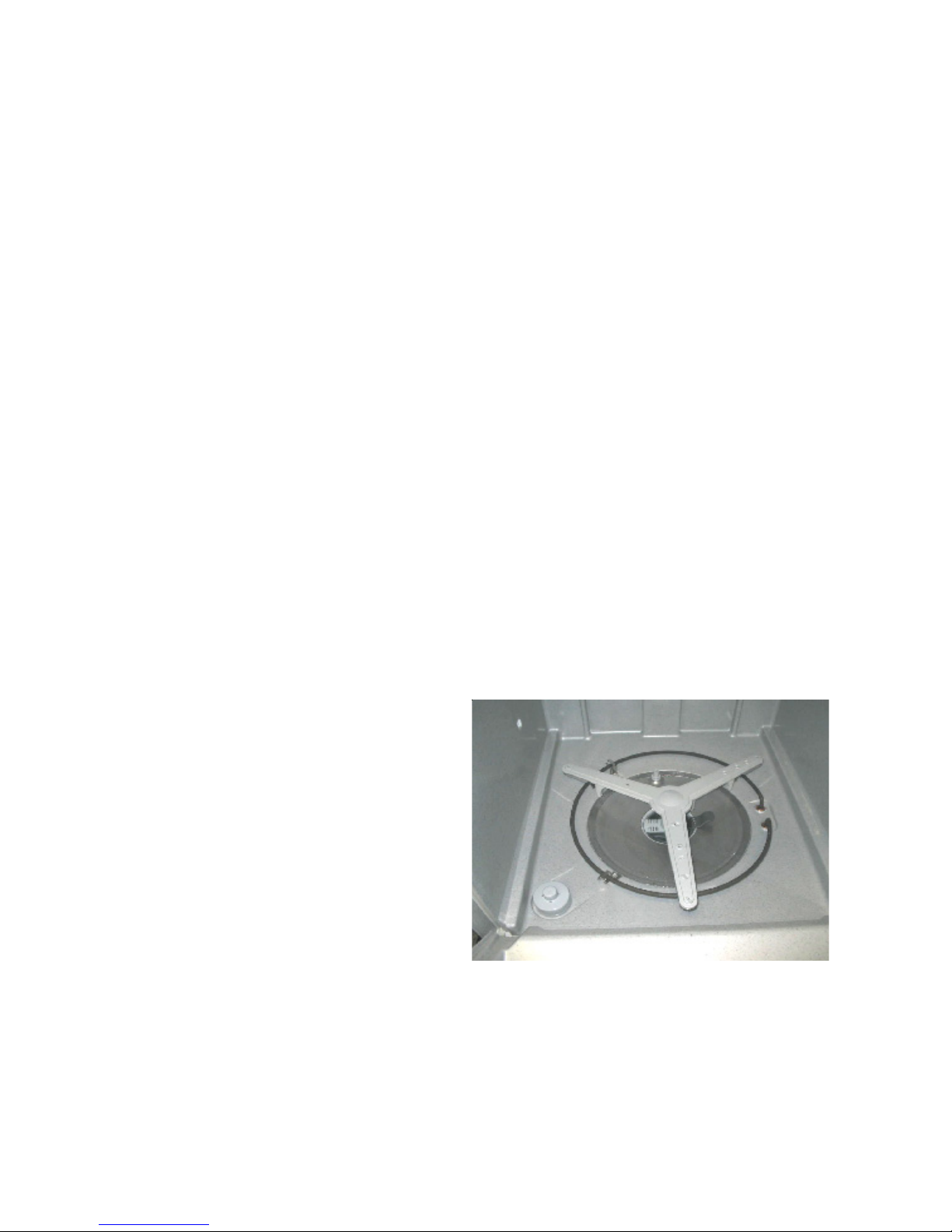
Figure 4
Below the lower spray arm is the filter and soil
director this covers the complete sump. The filter is
intended to block loosened food particles from
entering the wash sump area as they fall to the
bottom from the spray action. See Figure 4
8
On the underside of the filter is a soil director which
directs the loosened food particles to the lower left
side of the sump to a stainless steel food macerator
used to pulverize the soil so it can pass through the
drain hose. See Figure 5
Figure 5
The remaining parts in the wash system are the
sump assembly that acts as a reservoir for clean
water being supplied to the wash pump and the
delivery tube to supply water to the upper two spray
arms.
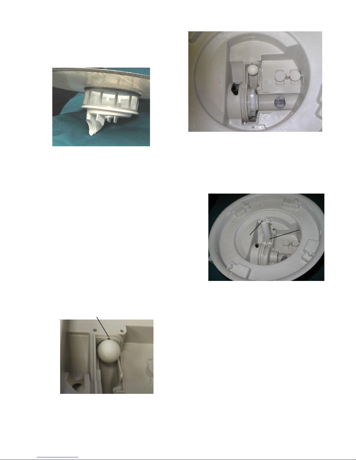
Figure 7
The check ball rests at the end of a ramp molded
into the sump partially blocking the rear hole. As
water under pressure enters the volute cover, the
check ball is held tightly into the rear hole restricting
water flow from this opening. Water can only leave
the remaining hole from the top of the volute cover
into the lower spray arm. See Figure 7
The Alternating Wash System
This wash system is designed to spray from only one
arm or one set of arms at a time. The advantage of
this is that it reduces the amount of water needed in
the tub. The way this system operates is explained
as follows.
Alternating the spray is achieved with a check ball
moving between two holes in the sump. One hole is
located in the rear of the sump used to supply water
to the upper two spray arms; the second is located
out the top of the volute cover onto which is mounted
the lower spray arm.
Bypass opening
Ball covering back hole
Figure 6
Volute cover
Opening to
lower spray
arm
Figure 8
The force of the water entering and leaving the arm
causes it to turn by the positioning of the hole in the
spray arm. The rear hole which is molded in the
sump has a small section removed above where the
check ball sets, this section allows a small amount of
water to by-pass the check ball and enter the delivery
tube mounted up the out side rear of the tub. Water
by-passing the check ball will fill the delivery tube at a
rate of approximately four inches a second. This
water will be used to change the spray from bottom
to the upper two spray arms. All wash and rinse
cycles will start by spraying from the lower wash arm.
Changing spray from bottom to upper spray arms is
accomplished with the control stopping the wash
pump for not more then .6 of a second. This pause
removes water pressure from the rear of the check
ball, water that had accumulated in the delivery tube
now reenter the sump, which moves the check ball
away from the hole and up the ramp.
9
Ball at the top of ramp
opening hole to center arm
The pump restarts the
water pressure in back
of the ball forces the
check ball up into the top
hole in the volute cover
blocking water tothe
lower spray arm. Water
exits the rear hole into
the delivery tube supplying water to the upper
spray arms.
Water in the delivery tube is divided with 80% going
to the center spray arm and 20% to the upper arm.
Water spray will continue from the upper spray arms,
after a predetermined time the control will again
pause the pump this time the pause will be for 3
seconds. This longer time allows for the delivery
tube to completely drain then the check ball returns
to the bottom of the ramp. The pump restarts with
spray from the lower spray arm completing a spray
arm change cycle.
Figure 9
The speed of the motor is determined by the elec-
tronic control based on the cycle selected. The
control continually monitors motor speed with input
from a Hall Effect sensor mounted to the rear of the
wash motor. Input voltage for operating the motor
will be 120VAC with the motor changing this to VDC
with a built-in rectifier.
Stainless Steel Filter
The stainless steel filter covers the entire sump area.
The filter is intended to remove all food particles from
the water so only clean water reenters the sump.
There is a fine mesh polyester screen housing in the
center of the stainless steel filter to house a lift out
basket to catch larger items, this basket can be
removed for cleaning. On the bottom of the inner
screen housing there is a soil director used to direct
food soil removed from the dishes to the left side of
the sump to be removed first when the water is
drained from the tub. The lower spray arm support
is also used as a lock for the filter to insure it is down
tight to the sump. See figure 11
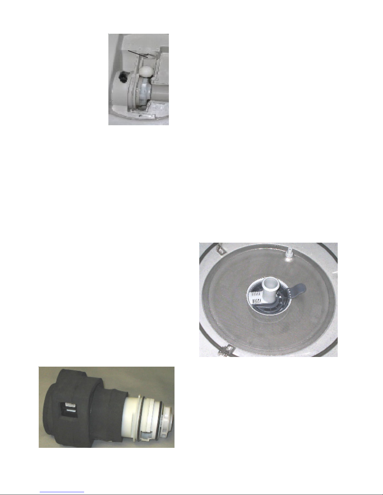
Parts in the wash System
Wash Pump
These model dishwashers use a variable speed DC
motor. The variable speed motor is used to improve cleaning by varying the water pressure
depending on the cycle selected. An Ultimate
Scrub and Maxx cycle intended for heavily soiled
dishes will have a high pressure speed to better
remove baked on food where a China/Crystal cycle,
for very delicate items will have a very low water
pressure setting. The user has an option to change
the motor speed on some models. There is an
added advantage of quieter operation when the
lower speed is used. The motor and wash pump
are supplied as a one piece assembly.
Figure 11
Figure 10
10
Lower Spray Arm
Upper Spray arm
This spray arm is designed using three spray arms to
spray water up into the lower rack. There are also
on the underside of this spray arms 4 legs used for
cleaning the soil from the stainless steel filter. Three
of the legs have spray openings pointed toward the
center these will spray water across the top of the
filter forcing the loosen soil to the center. The forth
leg is mounted closer to the center of the spray arm,
with a spray opening pointed straight down forces
food collected in the center basket down into the soil
director for removal in the drain segment of the wash
cycles. Turning of the arm is accomplished by water
under pressured sprayed from holes molded on top
of the arm these force the arm to turn in a clockwise
direction. The lower spray arm turns periodically in
all cycles, this to keep the filter clean, and reduce
chances of redeposit. See Figure 12
This arm is located in the top of the tub and turns in
a counter clockwise direction, and sprays simultaneously with the center spray arm. The mount for
the upper spray arm serves as the lock nut for the
delivery tube and is only available as an assembly.
The spray arm will turn at approximately 40 rpm.
See Figure 14
Figure14
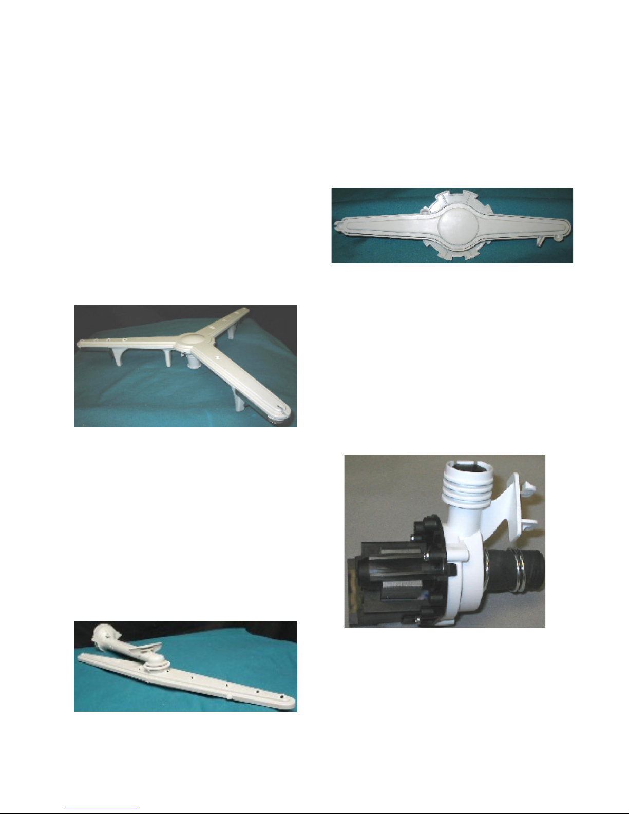
Drain Pump
The only function of the drain pump is to remove
water from the dishwasher. The drain pump is
mounted directly to the front of the sump. The
motor for this pump is rated a 1/25th hp drive motor.
The drain pump only comes as an assembly. The
front cover of the pump can be removed for cleaning
if needed.
Figure 12
Center Spray arm
This spray arm is mounted on a short delivery tube
to the under side of the upper rack. This arm rotates
clockwise at approximately 20 rpm. The center
spray arm and delivery tube will move in and out with
the upper rack. There is a bellows mounted to the
back end of this short delivery tube which forms a
seal against the back wall of the tub when the spray
arm is in operation. This delivery tube is also de-
signed for the adjustable upper rack. See Figure 13
Figure 13
Figure15
With the drain pump mounted in this location it is
accessible by removing both the outer door and the
toe kick panels. The drain pump connector hose
from the pump to the sump are supplied as an
assembly. See Figure 15
11
 Loading...