

Frigidaire Full Size Laundry Center Electric Installation Instructions Manual
Installation Instructions
Full Size Laundry Center Gas & Electric
Instrucciones para la instalación
Centro de lavanderia a gas y eléctrica
www.frigidaire.com
P/N134889400 (0706)
CONTENTS
SUBJECT PAGE
Pre-Installation Requirements .................................................................................................................................3
Electrical Requirements............................................................................................................................................3
Water Supply Requirements.....................................................................................................................................3
Drain Requirements..................................................................................................................................................3
Exhaust System Requirements..............................................................................................................................4-5
Gas Supply Requirements........................................................................................................................................5
Location....................................................................................................................................................................5
Rough-ln Dimensions ................................................................................................................................................6
Mobile Home Installation..........................................................................................................................................7
Unpacking.................................................................................................................................................................7
Electrical Installation.................................................................................................................................................8
Grounding Requirements.........................................................................................................................................8
3 & 4-Wire Connections .......................................................................................................................................8-9
Installation.............................................................................................................................................................9-10
ReplacementParts.....................................................................................................................................................10
Español...............................................................................................................................................................11-20
Laundry Center Safety
Before beginning installation, carefully read these instructions. This will simplify the installation
and ensure the laundry center is installed correctly and safely. Leave these instructions near the
laundry center after installation for future reference.
NOTE: The electrical service to the laundry center must conform with local codes and ordinances and the latest
edition of the National Electrical Code, ANSI/NFPA 70, or in Canada, the Canadian Electrical Code, CSA C22.1
NOTE: The gas service to the laundry center must conform with local codes and ordinances and the latest edition
of the National Fuel Gas Code ANSI Z223.1/NFPA 54, or in Canada, the Canadian Natural Gas and Propane
Installation Code, CSA B149.1.
NOTE: The laundry center is designed under ANSI Z21.5.1 or ANSI/UL 2158- CAN/CSA C22.2 No. 112 (latest
edition) for HOME USE only. This laundry center is not recommended for commercial applications such as restaurants or beauty salons, etc.
For your safety the information in this manual must be followed to minimize the risk of fire or explosion
or to prevent property damage, personal injury or loss of life.
- Do not store or use gasoline or other flammable vapors and liquid in the vicinity of this or any other appliance.
- WHAT TO DO IF YOU SMELL GAS
••
• Do not try to light any appliance.
••
••
• Do not touch any electrical switch; do not use any phone in your building.
••
••
• Clear the room, building or area of all occupants.
••
Immediately call your gas supplier from a neighbor’s phone.
••
• Follow the gas supplier’s instructions.
••
••
• If you cannot reach your gas supplier, call the fire department.
••
Installation and service must be preformed by a qualified installer, service agency or the gas supplier.
PRE-INSTALLATION REQUIREMENTS
Tools and Materials Required for Installation:
1. Phillips head screwdriver
2. Channel-Iock adjustable pliers
3. Carpenter’s level
4. Flat or straight blade screwdriver
5. Duct tape
6. Rigid or flexible metal 4 inch (10.16 cm) duct
7. Vent hood
8. Pipe thread sealer (Gas)
9. 1/4 inch socket w/ratchet
10. 3/8 inch socket w/ratchet
11. 3/8 inch open end wrench
12. 7/16 inch open end wrench
13. 9/16 inch open end wrench
ELECTRICAL REQUIREMENTS
ELECTRIC Laundry Center
Circuit- Individual 30 amp branch circuit fused with 30 amp
minimum time delay fuses or circuit breakers.
GAS Laundry Center
CIRCUIT -Individual 15 amp branch circuit fused with a 15
amp maximum time delay fuse or circuit breaker.
POWER SUPPLY -3 wire, 120 volt single phase, 60 Hz,
Alternating Current.
POWER SUPPLY CORD -The gas laundry center is equipped
with a 120 volt 3-wire power cord.
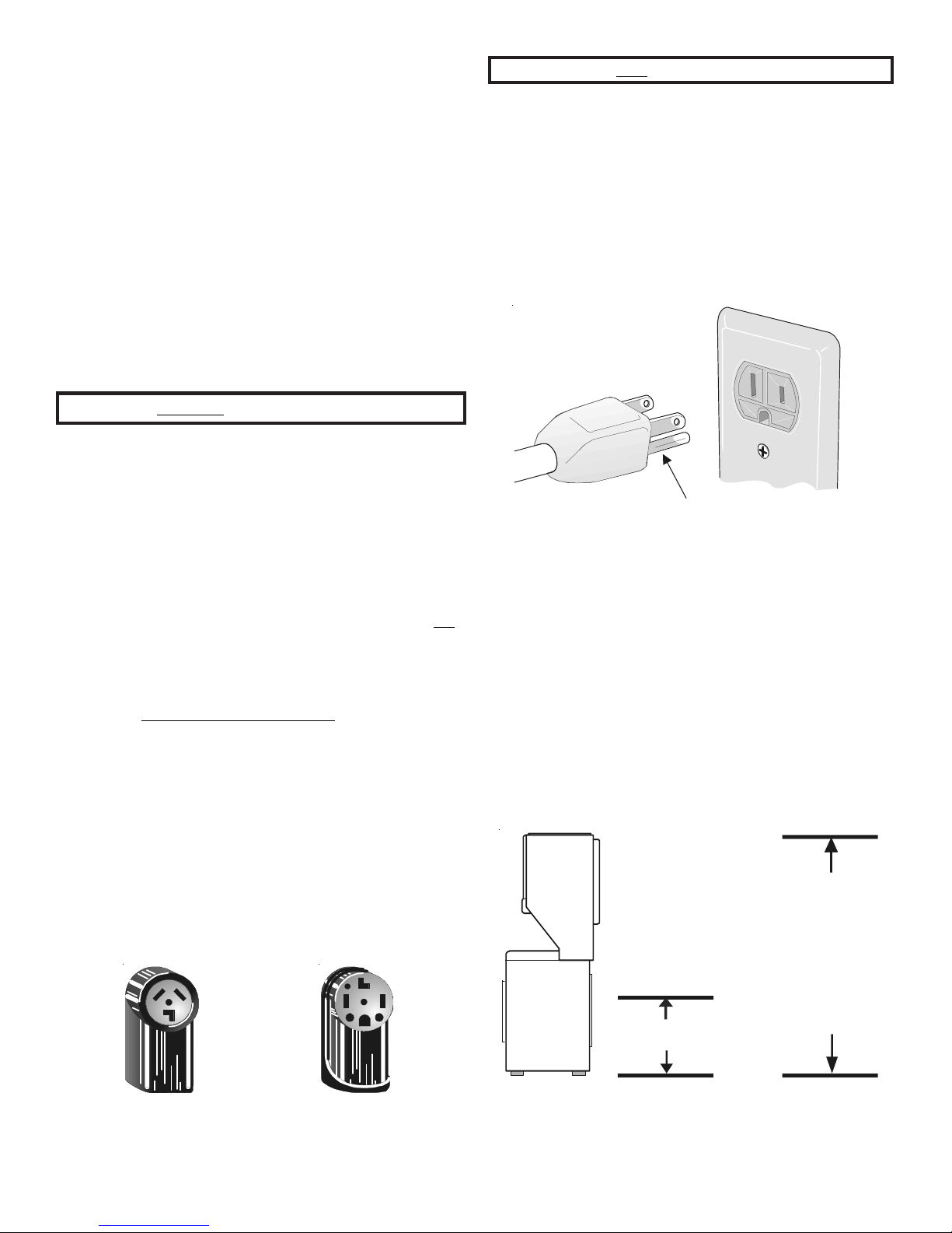
OUTLET RECEPTACLE - Properly grounded 3-prong
receptacle to be located so the power supply cord is
accessible when the washer is in an installed position. NOTE:
GFI (Ground Fault Interrupter) receptacle is not required or
recommended.
NOTE: Do not under
any circumstances
remove grounding
prong from plug.
POWER SUPPL Y - 3-wir e or 4-wire, 240 volt, single phase, 60
Hz, Alternating Current.
POWER SUPPL Y CORD KIT - The laundry center MUST employ
a 3-condutor power supply cord NEMA 10-30 type SRDT rated
at 240 volt AC minimum, 30 amp, with 3 open end spade lug
connectors with upturned ends or closed loop connector
4-condutor power supply cord NEMA 14-30 type SRDT or ST (as
required) rated at 240 volt AC minimum, 30 amp, with 4 open
end spade lug connectors with upturned ends or closed loop
connectors and marked for use with clothes dryers. If being
installed in a manufactured (mobile) home, the laundry center
MUST employ a 4-condutor power supply cord NEMA 14- 30
type SRDT or ST (as required) rated at 240 volt AC minimum,
30 amp, with 4 open end spade lug connectors with upturned
ends or closed loop connectors and marked for use with clothes
dryers. See ELECTRICAL CONNECTIONS. (Canada - 4-wire
power supply cord is installed on laundry center .)
OUTLET RECEPTACLE - NEMA 10-30R (3-wire) receptacle or
NEMA 14- 30R (4-wire) receptacle to be located so the power
supply cord is accessible when the laundry center is in an installed
position.
OR a
Grounding Prong
WATER SUPPLY REQUIREMENTS
Hot and cold water faucets MUST be installed within 42 inches
(106.68 cm) of your laundry center’s water inlet. The faucets
MUST be 3/4 inch (1.9 cm) garden hose type so inlet hoses
can be connected. Water pressure MUST be between 10 and
120 pounds per square inch (maximum unbalance pressure,
hot vs. cold, 10 psi). Y our water department can advise you of
your water pressure.
DRAIN REQUIREMENTS
1. Drain capable of eliminating 17 gallons per minute.
2. A standpipe diameter of 1¼ inches (3.18 cm) minimum.
3. The standpipe height above the floor should be:
Minimum height: 24 inches (61 cm)
Maximum height: 96 inches (244 cm)
96 in.
(244 cm)
Max.
NEMA 10-30R
NEMA 14-30R
24 in.(61cm)
Max.
NOTE: For installations requiring a longer drain hose, have a
qualified technician install a longer hose, Part Number
134042901, available from an authorized parts distributor. For
drain systems in the floor, install a siphon break kit, available
from your local hardware store .
3
EXHAUST SYSTEM REQUIREMENTS
Use only 4 inch (10.16 cm) diameter (minimum) rigid or flexible
metal duct and approved vent hood which has a swing-out
damper(s) that opens when the dryer is in operation. When the
dryer stops, the damper(s) automatically closes to prevent drafts
and the entrance of insects and rodents. T o avoid restricting the
outlet, maintain a minimum of 12 inches (38.5 cm) clearance
between the vent hood and the ground or any other obstruction.
1234546
The following are specific requirements
for proper and safe operation of your laundry center.
Failure to follow these instructions can create excessive
drying times and fire hazards.
1234546
to exhaust the dryer . Excessive lint can build up inside the exhaust
system and create a fire hazard and r estrict air flo
air flow will increase drying times. If your present system is
made up of plastic duct or metal foil duct,
or flexible metal duct. Ensure the present duct is free of any
lint prior to installing the laundry center dryer duct.
INCORRECT
Do not use plastic flexible duct or metal foil
w. Restricted
replace it with a rigid
INCORRECT
1234 546
Do not allow combustible materials (for
example: clothing,draperies/curtains, paper) to come in contact
with the exhaust system. The dryer MUST NOT be exhausted
into a chimney, a wall, a ceiling, or any concealed space of a
building which can accumulate lint, resulting in a fire hazard.
1234 546
Do not exceed the length of duct pipe or
number of elbows allowed in the” EXHAUST DUCT LENGTHS”
chart. Lint can accumulate in the system, plugging the system
and creating a fire hazard, as well as increasing drying times.
1234 546
Do not screen the exhaust ends of the vent
system, nor use any screws or rivets to assemble the exhaust
system. Lint can become caught in the screen, on the screws or
rivets, clogging the exhaust system and creating a fire hazard
as well as increasing drying times. Use an approved vent hood
to terminate the duct outdoors, and seal all joints with duct
tape. All male duct pipe fittings MUST be installed downstream
with the flow of air .
Explosion hazard.
1234 546
Do not install the laundry center where
gasoline or other flammables are kept or stored.If the laundry
center is installed in a garage, it must be a minimum of 18
inches (45.7 cm) above the floor. Failure to do so can result in
death, explosion, fire or burns.
The exhaust system back pressure MUST not exceed 0.6 inches
(1.52 cm) of water column measured with an inclined
manometer at the point the exhaust connects to the dryer .
The exhaust system should be inspected and cleaned a minimum
of every two years with normal usage. The more the dryer is
used, the more often you should check the exhaust system and
vent hood for proper operation.
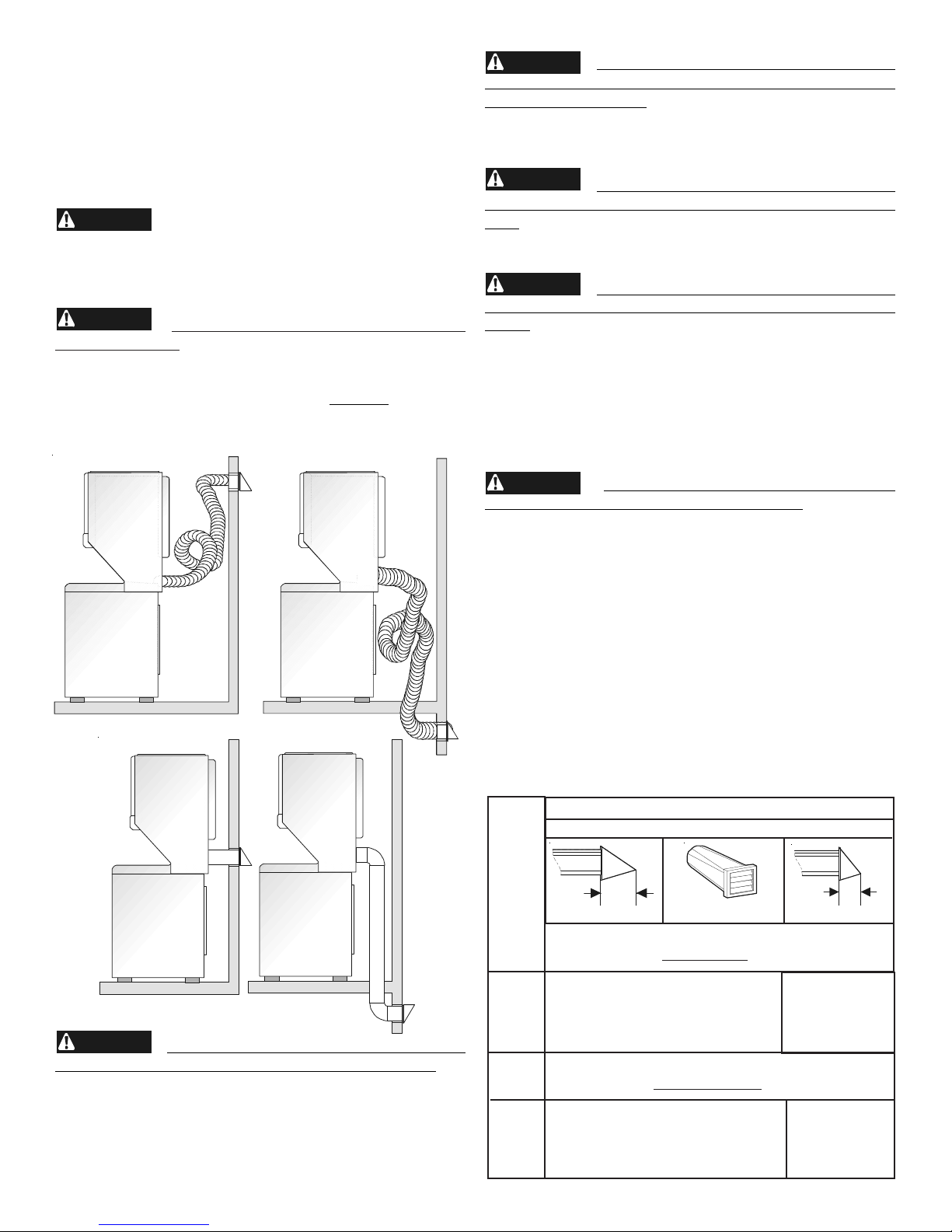
The maximum length of the exhaust system depends upon the
type of duct used, number of elbows and type of exhaust hood.
The maximum length for both rigid and flexible duct is shown in
the chart below.
EXHAUST DUCT LENGTHS
EXHAUST HOOD TYPE
CORRECT CORRECT
1234546
If the dryer is not exhausted outdoors,
some fine lint will be expelled into the laundry area. An
accumulation of lint in any area of the home can create a
health and fire hazard. The dryer exhaust system MUST
be exhausted to the outside of the dwelling!
Number
4
of 90°
T urns
0
1
2
3
0
1
2
3
4”
(10.2 CM)
MAXIMUM LENGTH OF 4-INCH (10.2 CM)
DIAMETER
56 ft. (17.07 m)
46 ft. (14.02 m)
34 ft. (10.36 m)
32 ft. (9.75 m)
MAXIMUM LENGTH OF 4-INCH (10.2 CM)
DIAMETER
30 ft. (9.14 m)
22 ft. (6.7 m)
16 ft. (4.88 m)
NOT RECOMMENDED
Louvered
RIGID METAL DUCT
42 ft. (12.8 m)
36 ft. (10.97 m)
28 ft. (8.53 m)
18 ft. (5.48 m)
FLEXIBLE METAL DUCT
22 ft. (6.7 m)
14 ft. (4.27 m)
10 ft. (3.05 m)
2.5”
(6.35 CM)
The laundry center may be exhausted four (4) ways with rear
flush installation:
1. Straight back
2. Down (8 inch [20.32 cm] length of 4 inch [10.16 cm]
rigid duct and 1 elbow down)
3. Left (8 inch [20.32 cm] length of 4 inch [10.16 cm]
rigid duct, 1 elbow down and 1 elbow left)
4. Right (8 inch [20.32 cm] length of 4 inch [10.16 cm]
rigid duct, 1 elbow down and 1 elbow right)
To exhaust up, add an 11 inch
(27.94 cm) length of standard 4
inch (10.16 cm) diameter duct
and a 90° elbow. The unit will be
positioned about 4½ inches
(11.43 cm) away from the wall
(flush to wall exhausting may be
done by going below the dryer
then sideways).
An exhaust hood positioned to
line up with the dryer exhaust can
be installed directly through the
outside wall. To exhaust to the
side or down, add an 8 inch
(20.32 cm) length of standard 4
inch (10.16 cm) diameter duct and
a 90° elbow.
GAS SUPPLY REQUIREMENTS
1. Installation MUST conform with local codes, or in the
absence of local codes, with the National Fuel Gas Code,
ANSI Z223.1 (latest edition) or in Canada, the current AN/
CGA B149.
2. The gas supply line should be of 1/2 inch (1.27 cm) pipe.
3. If codes allow, flexible metal tubing may be used to connect
your dryer to the gas supply line. The tubing MUST be
constructed of stainless steel or plastic-coated brass.
4. The gas supply line MUST have an individual shutoff valve.
5. A 1/8 inch (0.32 cm) N. P. T. plugged tapping, accessible
for test gage connection, MUST be installed immediately
upstream of the gas supply connection to the dryer.
6. The dryer and its individual shutoff valve MUST be
disconnected from the gas supply piping system during
any pressure testing of the gas supply piping system at
test pressures equal to or less than 1/2 psig (3.45 kPa).
7. The dryer MUST be isolated from the gas supply piping
system by closing its individual manual shutoff valve during
any pressure testing of the gas supply piping system at
test pressures equal to or less than 1/2 psig (3.45 kPa).
LOCATION OF YOUR LAUNDRY CENTER
DO NOT INSTALL YOUR LAUNDR Y CENTER:
1. In an area exposed to dripping water or outside weather conditions.
2. In an area where it will come in contact with curtains or drapes.
3. On carpet. Floor MUST be solid with a maximum slope of 1 inch (2.54 cm).
4. On a pedestal. Excessive vibration can occur.
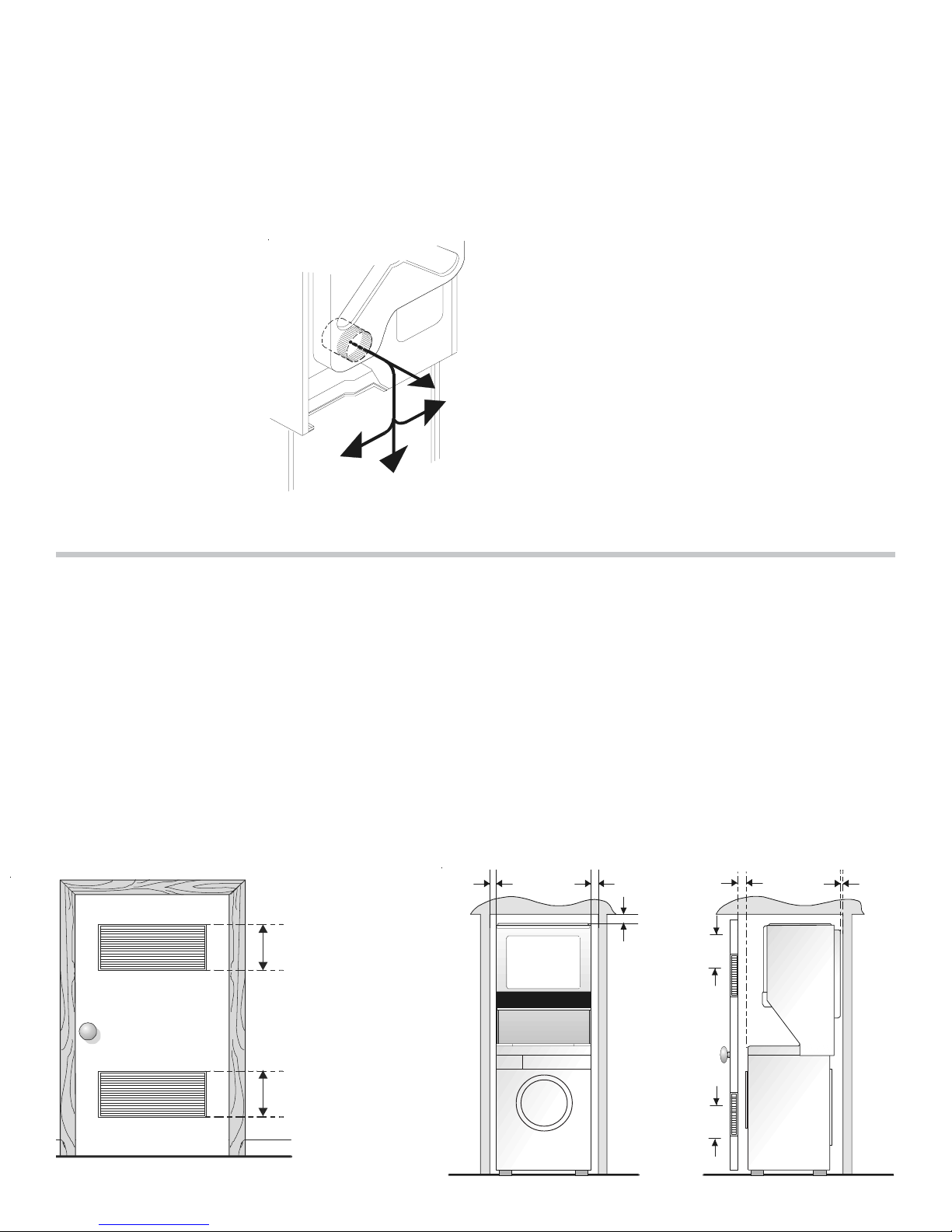
INSTALLA TION IN RECESS OR CLOSET
1. A laundry center installed in a bedroom, bathroom, recess or closet, MUST be exhausted outdoors.
2. No other fuel burning appliance shall be installed in the same closet as the Gas laundry center.
3. Y our laundry center needs the space ar ound it for proper ventilation.
DO NOT INSTALL YOUR LAUNDRY CENTER IN A CLOSET WITH A SOLID DOOR.
4. A minimum of 120 square inches (774.2 square cm) of opening, equally divided at the top and bottom of the door, is
required. Air openings are required to be unobstructed when a door is installed. A louvered door with equivalent air
openings for the full length of the door is acceptable.
5. The following illustrations show minimum clearance dimensions and air openings for proper operation in a recess or closet
installation.
60 SQ. IN.
(387.1 SQ. CM)
0 IN.
(0 C M)
0 IN.
(0 CM)
DRYER
1 IN.
(2 .5 4 C M)
60 SQ. IN.
(387.1 SQ. CM)
0 IN.
(0 C M)
60 SQ. IN.
(387.1 SQ. CM)
Closet Door
WASHER
60 SQ. IN.
(387.1 SQ. CM)
5
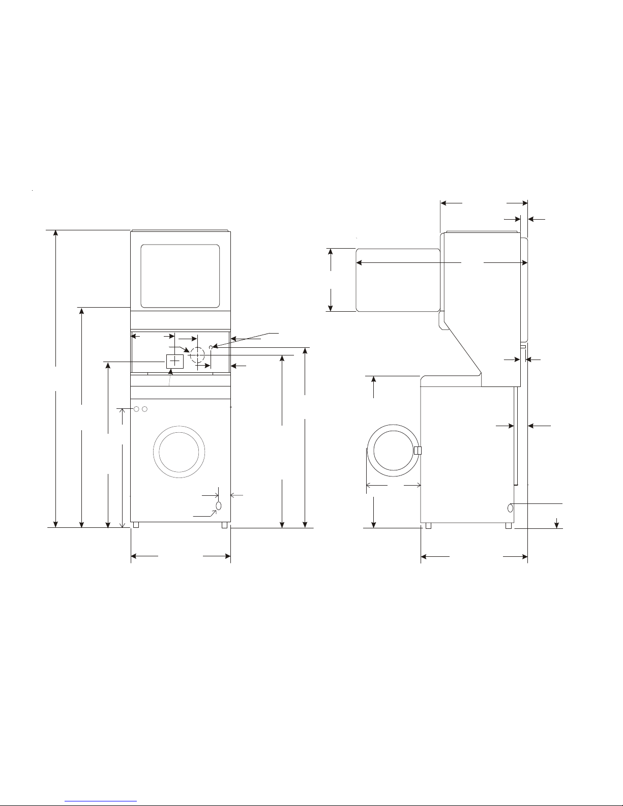
ROUGH-IN DIMENSIONS
25 ¼ IN.
(64.13 CM)
3 ¾ IN.
(9.52 CM)
4 13/16 IN.
(12.22 CM)
9 3/8 IN.
(23.81 CM)
2 ½ IN.
(6.35 CM)
47“
16 ¼ IN.
(41.27 CM)
36 1/16IN.
(91.60 CM)
30 13/16 IN.
(78.26 CM)
11 7/16 IN.
(29.5 CM)
41 ¼ IN
(104.77 CM)
29 7/16 IN
(74.77 CM)
27 IN.
(68.58CM)
DRAIN OUTLET
(REAR)
WATER INLETS
(REAR)
VENT
1 7/8 IN.
(4.76 CM)
5 ¼ IN.
(13.33 CM)
GAS SUPPLY
PIPE (REAR)
43 IN.
(109.22 CM)
54 5/16 IN.
(137.95 CM)
75 ½ IN.
(191.77 CM)
43 IN.
(109.22 CM)
ELECTRICAL
CONNECTION
12 ½ IN.
(31.75 CM)
DRAIN OUTLET
(REAR)
42¼ IN.
(107.32 CM.)
53 IN.
(134.62 CM.)
75¼ IN.
(191.14 CM.)
36 IN.
(91.44 CM.)
29¾ IN.
(75.57 CM.)
3 IN.
(7.62 CM.)
31/8 IN.
(7.94 CM.)
17½ IN.
(44.45 CM.)
44 IN.
(111.76 CM.)
31¾ IN.
(80.65 CM.)
40½ IN.
(102.87 CM.)
 Loading...