

TECH SHEET - RETAIN FOR SERVICE TECHNICIAN
Disconnect from Electrical Supply Before Servicing Washer.
Timer/off
Door/open
LINE SWITCH
PUSH-PULL
GND
BLK/WHT
L1
DOOR
LOCK
COIL
WHT
N
GRN
0T 0C
BLK
#4
BLEACH
4.4
2.1
2
BLEACH
DOOR
LAMP
1
2
2B
WHT/RED
WHT
DISPENSER
2.2
DOOR
LOCK
SWITCH
SOFTENER
VALVES
4.3
TAN/BLK
ORG/WHT
SOFTENER
Motor Will Not Run
1. CHECK FOR POWER:
Advance the timer knob to the drain
increment. If the drain pump does not run,
check household safety circuit. If the drain
pump runs go to step 2.
2. CHECK FOR MOTOR MOVEMENT:
Turn the water off to the washer. Remove
electrical power from the washer and
remove the back
drive belt. Reconnect electrical power and
set the timer to the start of the Regular wash
cycle and pull the knob out. If motor does
not rotate, check for a poor connection in the
timer line switch or door lock switch. If good,
and motor does not run
3. MEASURE VOLTAGES:
Remove the six pin plug from the speed
control unit. Measure the voltage between
pins 5 and 6 on the harness. If the meter
reads 0 check the connection in the timer
line switch or door lock. If the meter
reads 120 Vac go to step 4.
6
1
This information is intended for use by technicians possessing
adequate background of electrical, electronic and mechanical
experience. Any attempt to repair a major appliance may result in
personal injury and property damage. The manufacturer or seller
cannot
be responsible for the interpretation of this information, nor
can it assume any liability in connection with its use.
panel. Remove the motor
go to step 3.
Speed
Control
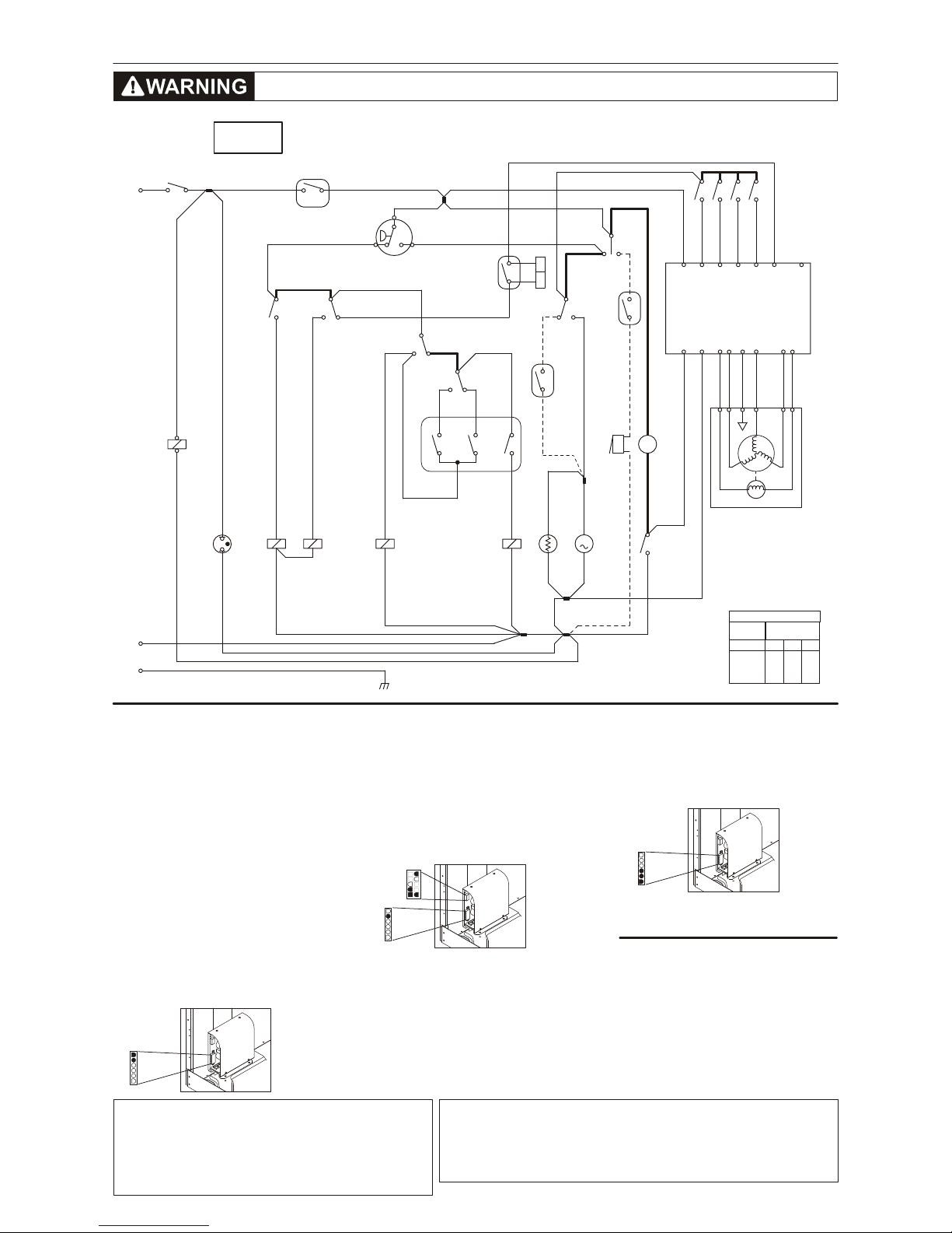
WIRING DIAGRAM
#6
BLK/RED
1
AQUA
3
2
WATER LEVEL
PRESSURE
SWITCH
TAN
T
B
4
RINSE
WATER
BLUE
BLUE
COLD
CABINET
CHASSIS
4. Set the timer to the Heavy Wash position of
the Regular wash cycle. Remove the ten pin
plug from the speed control unit. Measure
the voltage between pins 1, 2, 6 and 10 of
the ten pin plug to pin 5 of the 6 pin plug on
the harness. The voltage at pins
10 should read 120 Va c and 0 Vac at pin 1.
If not, check timer contacts 1C to 1B, 5C to
5B, and 7C to 7B for closed contacts, and
3C to 3B for open contacts. If the voltage
readings are correct, go to step 5.
510
6
16
1
5. MEASURE RESISTANCES:
Check the
If the fuse is open, replace the speed control
board. If good, go to step 6.
6. Remove the 6 pin plug from the speed
control unit. Measure the resistance
between pins 1 and 2, 2 and 3, and 3 and 1
of the speed control unit. If the
other than 3 Meg ohms ± 10%, replace the
speed control board.
WAX MOTOR
SWITCH
WASH
WATER
B
T
8
RINSE
WASH
WATER
WATER
10
T
B
RED/YEL
3
5
14
TEMP
SWITCH
WATER
VALVES
fuse on the speed control board.
If grounding wires, screws or clips used to complete a path to ground are removed
for service, they must be returned to their original position and properly fastened.
Certain internal parts are intentionally NOT grounded and may present a risk of
electric shock only during servicing. Do not contact the following
appliance is energized: pump, drive motor and electronic control boards.
YEL/BLK
TIMER
1
2
YEL/RED
+t
PTC
MOTOR
TEST CONNECTOR
T
T
EXTRA
RINSE
SWITCH
WAX
WHT
WHT
14
#3
#7
DIRECT
B
4.1
4.2
RED
BROWN
ORG
2
YEL
HOT
#1
WHT
NOTE: BOLD LINES INDICATE INTERNAL TIMER JUMPER WIRES.
DASHED LINES INDICATE CIRCUITS NOT ON ALL MODELS.
2, 6, and
CYCLE
SIGNAL
T
B
12
GRAY
SIGNAL
SWITCH
ORG/GRAY
CYCLE
SIGNAL
MS
#2
PINK
1
PUMP
M
MOTOR
2
MOTOR
6C
6T
7. Remove electrical power from the washer.
With an ohmmeter check the resistance
between pins 1 and 2, 2 and 3, and 3 and 1
of the six pin plug on the harness. If the
meter reads other than 2.6 ohms
replace the motor.
6
Speed
Control
meter reads
1
• The timer motor will not run continuously.
The speed control unit controls the timer
motor and advances the timer when needed.
•In some tumble modes, the tub may not
tumble for the first 16 to 20 seconds after
start-up.
• Extremely low water pressure may cause
tub rotation to stop until WLC satisfied.
IMPORTANTIMPORTANT SAFETY NOTICE
C6.6 (AC)
C10.5 (TM)
YEL/BLK
TIMER
Quick Facts
7C5C3C1C
7B5B3B1B
BLUE
C10.2 (A)
MOTOR CONTROL
C6.5 (AC)
PINK/BLK
C10.1 (B)
C10.4 (T1)
YEL/WHT
653
MOTOR
WINDING
WHT/RED
C6.1 (P1)
TAN/WHT
SWITCH
POSITION
*
*
BROWN
WHT/RED
C10.9 (E)
C10.6 (C)
C10.10 (D)
C6.4
C6.2 (P2)
C6.3 (P3)
GREEN
RED/BLK
ORG/BLK
24
1
T
TACHO-
GENERATOR
WATER TEMP SWITCH
CIRCUIT
1 - 31 - 5
H/C
W/C
C/C
W/W
XXX
X= CONTACTS CLOSED
NOT ON ALL MODELS
C10.3 (T2)
YELLOW
2 - 4W/R
XX
± 7%,
Speed
Control
parts while the
PART NO. 134968300 A
X
X
!
WARNING
This information is intended for use by persons having electrical and mechanical training and a level of
knowledge of these subjects generally considered acceptable in the appliance repair trade. The
manufacturer or seller can not be responsible, nor assume any liability, for injury or damage of any kind
arising from the use
If grounding wires, screws or clips used to complete a path to ground are removed for service, they
must be returned to their original position and properly fastened. Certain internal parts are intentionally
NOT grounded and may present a risk of electric shock only during servicing. Do not contact the
following
parts while the appliance is energized: pump, drive motor and electronic control boards.
NOTE: BOLD LINES INDICATE INTERNAL TIMER JUMPER WIRES.
DASHED LINES INDICATE CIRCUITS NOT ON ALL MODELS.
IMPORTANT
of this data.
0T
TIMER
0C
2.2
DOOR
LOCK
4.3
WATER LEVEL
1
SWITCH
2
3
TIMER
2C
4C
TIMER
4B
IF NO WARM OR COLD WATER DURING RINSE FILL (SOFTENER)
8C 1 10T 2
TIMER TEMP
8B 3 10C 4
SWITCH
TIMER
DOOR
LOCK
WATER LEVEL
SWITCH
TIMER
0T
IF NO COLD WATER DURING RINSE FILL (BLEACH)
0C
2.2
4.3
1
2
3
2C
2B
TIMER
TIMER
0T
IF NO HOT, WARM OR COLD WATER DURING WA SH FILL (DETERGENT)
TIMER
0C
2.2
DOOR
LOCK
4.3
WATER LEVEL
1
SWITCH
2
3
TIMER
2C 8B4C
4C
8C
8C
TIMER
8B
8T
10C
TIMER
10B
LOCK
TIMER
DOOR
TIMER PUMP
TIMER EXTRA
0T 0C
2.2
4.3 14T 212T
12C
14C 1
IF WATER PUMP DOES NOT WORK IN EXTRA RINSE
LOCK
0T
TIMER
0C
2.2
DOOR
4.3
12C
TIMER
12T
14C
TIMER
14B
IF WATER PUMP DOES NOT WORK
LOCK
MOTOR
0T
TIMER
0C
DOOR
TIMER
TIMER
IF TIMER WON'T ADVANCE
0T
TIMER
0C
2.2
4.3
12C
MS
LOCK
DOOR
TIMER
TIMER
2.2
4.3
12C
12T
14C
14B
IF DOOR LOCK OPENS DURING SPIN
TIMER
DOOR
LOCK
TIMER
SWITCH
SIGNAL
IF NO END-OF-CYCLE SIGNAL (BUZZER)
0T
0C
2.2
4.3
12C
12B
CYCLE
DOOR LAMP
21
COIL
TIMER
DOOR LOCK
0T
0C
L1 N
DOOR LOCK SOLENOID WON'T ENERGIZE
DOOR LAMP WON'T LIGHT OR
4.4 2.1
SOFTENER
SOLENOID
SOLENOID
BLEACH
TIMER TEMP
SWITCH
HOT WATER
SOLENOID
COLD WATER
SOLENOID
SOLENOID
BLEACH
COLD WATER
SOLENOID
5
SWITCH
TEMP
1
TIMERTIMER
COLD WATER
SOLENOID
2
SWITCH
TEMP
4
HOT WATER
SOLENOID
RINSE
MOTOR
1
MOTOR
M
2
PUMP
6C
TIMER
6T
C10.5 C6.5
1
M
2
CONTROL
SPEED
SIGNAL
CYCLE
MOTOR
WAX
PTC
+t
L1 N
0T 0C
TIMER
(AC)
(AC)
C6.6
C6.5
LOCK
TIMERTIMER
WAX MOTOR
DOOR
2
2C
4C
4T
4.2
4.1
2.2 4.3
C10.9 (E)
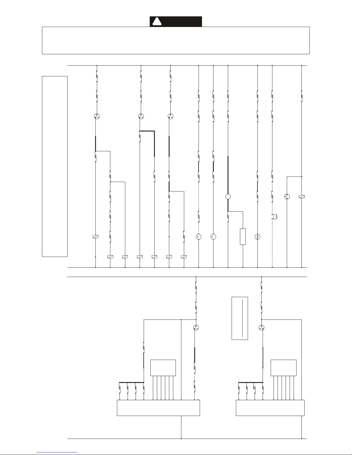
DIAGNOSTIC STRIP CIRCUITS
12C
(PHASE 1) 3
(PHASE 2) 2
(GND) 4
C6.4 (GND)
(PHASE 3) 1
(TACH) 6
(TACH) 5
C6.1 (P1)
C6.2 (P2)
C6.3 (P3)
C10.3 (T2)
C10.4 (T1)
MOTOR
TIMERTIMER
14C12T
3C
5C
7C
TIMER
TIMER
5B
PART NO. 134968300 A
7B
CONTROL
SPEED
C10.10 (D)
C10.6 (C)
TIMER
1C
TIMER
1B
3B
C10.1 (B)
C10.2 (A)
IF NO MOTOR ROTATION DURING SPIN
MACHINE FUNCTION.
MOTOR CONTROL CODE AND
REFER TO TIMER CHART FOR THE
WATER LEVEL
1
SWITCH
3
* 7C
TIMER
TIMER
7B
C10.10 (D)
CONTROL
SPEED
TIMER CONTACTS 1, 3, 5 AND 7:
5B
REGULAR WASH CYCLE.
AT THE START OF THE
* 5C
C10.6 (C)
* TIMER CONTACTS SHOWN
TIMER
TIMER
DOOR
LOCK
WATER LEVEL
SWITCH
* 3C
3B
C10.1 (B)
0T 0C
2.2 4.3
2
TIMER TIMER
TIMER
IF NO MOTOR ROTATION DURING FILL OR AGITATION
1
3
12T 14C
(PHASE 1) 3
(PHASE 2) 2
MOTOR
(PHASE 3) 1
(TACH) 5
(TACH) 6
(GND) 4
* 1C
1B
C6.4 (GND)
C10.3 (T2)
C10.4 (T1)
C10.2 (A)
C6.6
(AC)
C6.1 (P1)
C6.2 (P2)
C6.3 (P3)
C6.5
(AC)

FEUILLE DE TECHNOLOGIE-MAINTENEZ POUR LE
TECHNICIEN DE SERVICE.
AVERTISSMENT
BOUTON À
TIRER DE LIGNE
NOIR/
L1
BLANC
0T 0C
DU LOCQUET
N
MISE À
LA TERRE
SOLÉNOIDE
DE PORTE
4.4
2.1
BLANC
VERT
MINUTERIE/FERMÉ
PORTE/OUVERT
NOIR
#4
JAVÉLLISANT
2
LUMIÉRE
1
DE PORTE
Débranchez L’Alimentation Avert Tout Travail De Réparation Ou D’Entretien
SCHÉMA DE CÂBLAGE
2.2
INTERRUPTEUR
DU LOQUET
DE LA PORTE
2
2B
BLANC/ROUGE
D’EAU SEJAVÉLLISANT
BLANC
SOLÉNOIDE
DU ROBINET
DISTRIBUTEUR
4.3
OCRE/NOIR
ADOUCISSEUR
B
4
ORG/BLANC
D’EAU SE ADOUCISSEUR
MISE À LA
TERRE DU BOÎTIER
JAUNE/NOIR
NOIR/ROUGE
1
2
INTERRUPTEUR
NIVEAU D’EAU
OCRE
T
D’EAU
RINÇAGE
BLEU
BLEU
ROBINET
#6
EN DIRECT
CONNECTEUR D'ESSAI
JAUNE/ROUGE
+t
PTC
MINUTERIE
TB
14
DE RINÇAGE
INTERRUPTEUR
ROSE
#3
BLANC
#7
BLANC
BLEU VERT
3
COMMUTATEUR
DE MOTEUR
DE CIRE
D’EAU
LAVAGE
B
T
8
D’EAU
RINÇAGE
JAUNE
ROUGE/
3
DE TEMPÉRATURE
FROID
D’EAU
NOTE: LES LIGNES ÉPAISSES INDIQUENT DES FILS DE PULLOVER INTERNES DE TEMPORISATEUR
LES LIGNES EN TRAITS INDIQUENT LES CIRCUITS NON DISPONIBLES DANS CERTAINS MODÈLES.
4.1
1
2
4.2
ROUGE
D’EAU
LAVAGE
5
CHAUD
ROBINET
D’EAU
ORG
2
BRUN
JAUNE
BLANC
CIREZ LE
MOTEUR
#1
10
T
B
14
COMMUTATEUR
INTERRUPT
AVERTISS
SUPPLÉMENTAIRE
#2
1
M
2
T
12
AVERTISSEUR
MOTEUR
DE POMPE
SIGNAL
SONORE
B
ORG/GRIS
GRIS
MS
MINUTERIE
MOTEUR DE
6C
6T
BLEU
C10.2 (A)
C6.6 (AC)
RÉGULATEUR DU MOTEUR
C10.5 (TM)
C6.5 (AC)
JAUNE/NOIR
7C5C3C1C
7B5B3B1B
BRUN
ROSE/NOIR
BLANC/ROUGE
BLANC/ROUGE
C10.1 (B)
C10.6 (C)
C10.10 (D)
C6.4
C10.4 (T1)
C6.1 (P1)
C6.2 (P2)
VERT
ORG/NOIR
JAUNE/BLANC
OCRE/BLANC
24
653
MOTEUR
T
GÉNÉRATRICE DE TACHYMÈTER
COMMUTATEUR DE TEMPÉRATURE
LAVAGE/
RINÇAGE
C/F
T/F
F/F
C=CHAUD T=TIÉDE
F=FROID X=FERMÉS
*PAS SUR TOUS LES MODÈLES
C10.9 (E)
C10.3 (T2)
C6.3 (P3)
JAUNE
ROUGE/NOIR
1
CIRCUIT
1 - 31 - 5
XXX
2 - 4
X
XX
X* T/T
Non Fonctionner Moteur
1. VÉRIFIEZ L'ALIMENTATION :
Tournez le bouton de la minuterie en position
vidange. Si la pompe de vidange ne
fonctionne pas, vérifiez le circuit d'alimentation
de la ré
sidence. Si la pompe de vidange fonctionne,
passez à l'étape 2.
2. VÉRIFIEZ LE FONCTIONNEMENT DU MOTEUR:
Fermez l'arrivée d'eau à la
Coupez l'alimentation à l'appareil et retirez le
panneau arrière. Retire z la courroie d'entraî
nement du moteur. Rebranchez l'alimentation
et placez le bouton de la minuterie en position
départ cycle de lavage régulier et tirez le
bouton. Si le moteur ne fonctionne pas, vérifiez
s'il existe de mauvais
l'interrupteur de la minuterie ou de l'interrupteur
de la porte. Si ces circuits sont corrects et
que le moteur ne fonctionne pas, passez à
l'étape 3.
3. MESUREZ LA TENSION :
Retirez les six connecteurs à broche de l'unité
de commande de vitesse. Mesurez la
entre les connecteurs 5 et 6 sur le harnais. Si le
lecteur indique 0, vérifiez la connexion dans le
circuit de l'interrupteur de la minuterie ou de
l'interrupteur de la porte. Si la lecture indique
120 Vac, passez à l'étape 4.
6
1
machine à laver.
contact dans le circuit de
tension
RÉGULATEUR
DE VITESSE
4. Placez le bouton de la minuterie en position
Gros Lav a g e du cycle de lavage régulier.
Retirez les dix connecteurs en broches de
l'unité
de commande de vitesse. Mesurez la tension
entre les connecteurs1, 2, 6 et 10 des dix
connecteurs en broche au connecteur 5 des 6
connecteurs en broche du harnais. La tension
au connecteur 2, 6 et 10 devrait indiquer 120
Vac
et 0 Vac au connecteur 1. Si ce n'est pas
le cas, vérifiez les contacts de la minuterie de
1C à 1B, 5C à 5B et 7C à 7B pour les contacts
ouverts et 3C à 3B pour les contacts fermés. Si
les lectures de tension sont correctes, passez à
510
l'étape 5.
6
16
1
5. MESUREZ LA RÉSISTANCE :
Vérifiez les fusibles sur la carte de commande de
vitesse. Si le fusible est fermé, remplacez la
carte de commande de vitesse. Si le fusible est
bon, passez à l'étape 6.
6. Retirez les 6 connecteurs à broche de l'unité
de commande de vitesse. Mesurez la résistance
entre le connecteur 1 et 2, 2 et 3, et 3 et 1 de l'unité
de commande de vitesse. Si les lectures indiquent 3
Meg ohms 10%, remplacez la carte de l'unité de
commande de vitesse.
Ces renseignements sont destinés aux techniciens
ayant l'expérience adéquate en électricité,
électronique et mécanique. Toute tentative de
réparer un gros appareil électroménager peut causer
des blessures ou des dommages. Le fabricant ou le
vendeur ne peut être responsable de l'interprétation
de ces renseignements, ni assumer quelque
responsabilité que ce
IMPORTANT
soit relative à leur utilisation.
RÉGULATEUR
DE VITESSE
7. Débranchez l'alimentation de la machine à laver.
Avec un ohmmètre, vérifiez
connecteurs 1 et 2, 2 et 3, et 3 et 1 des six
connecteurs à broche du harnais. Si les lectures ne
sont pas 2.6 ohms 7%, remplacez le moteur.
6
1
Le moteur de la minuterie ne fonctionne pas
continuellement. L'unité de commande de vitesse
contrôle le moteur de la minuterie et fait avancer la
minuterie s'il y a lieu.
Dans certains modes de culbutage, il est possible
que la cuve ne puisse culbuter durant les 16 à 20
premières secondes qui suivent le démarrage.
Une pression d'eau extrêmement basse peut arrêter
la rotation de la cuve jusqu'à ce que le niveau d'eau
requis (WCL) soit atteint.
Si les fils, vis ou attaches de mise à la terre utilisés
pour mettre à la terre un circuit sont démontés pour
fins de tout travail d'entretien ou de réparation, ils
doivent être remontés à leur emplacement original
et solidement fixés. Certaines pièces internes sont
intentionnellement NON mises
présenter des risques de choc durant tout travail
d'entretien ou de réparation. N'entrez pas en
contact avec les pièces suivantes si l'appareil est
alimenté : la pompe, le moteur d'entraînement
et les cartes de commande électroniques.
AVIS SÉCURITÉ IMPORTANT
la résistance entre les
RÉGULATEUR
DE VITESSE
à la terre et peuvent
No DE PIÉCE 134968300 A

AVERTISSEUR
Cette information est destinée aux techniciens ayant des connaissances et de l’expérience en électricité,
electronique et mécnique. To u t e tenative de réparer un appareil majeur peut entraîner des blessures et des
dommages. Le fabricant ou le vendeur no peuvent être tenus responsables d’une compréhension ou d’une
interprétation erronée de cette information ni
assurmer quelqueresponsabilitéque ce soit relative à son usage.
0T
MINUTERIE
0C
LOCQUET DE PORTE
SOLÉNOÏDE DU
L1 N
LE SOLÉNOÏDE DE SERRURE DE PORTE N’ACTIVERA PAS
LA LAMPE DE PORTE NE LUMIÉRE PAS OU
4.4 2.1
ta i qu ’ ppa e l t v pom ez mo r ’ tr îne nt
dé ha g l tri i ue seul m
Ce aines pi i terne ne on as in ti nel e ent due i peu en er un iq de r èces n s st p ten on l m fon s t vt présent rs ue
enlev s ur lvie, l do v t êee i en eu p i i orig na e et r c e tem nt acsé po e ser c i s i en tr rms l r os t on il êt e orr c e tta hé .
S des fi s de se,es vs ou es grafe ut l s s ur ac pl er u h i pou rec i er snt il ma s li, l asiiée po com i n cemn r t fi o
pen nt le e N’ tr z s n c nta t aec l p èc s u v tes cre é ec c q e ent da ’ ntreti n.
IMPORTANT
en e pa eocv esie
e abl aux de om and l t on qund s e la r i ac i e: p , teu d en a me t te cm e éecr i e.
sian
NOTE: LES LIGNES ÉPAISSES INDIQUENT DES FILS DE PULLOVER INTERNES DE TEMPORISATEUR
LES LIGNES EN TRAITS INDIQUENT LES CIRCUITS NON DISPONIBLES DANS CERTAINS MODÈLES.
MINUTERIE
0T
0C
2.2
DE PORTE
LOCQUET
4.3
INTERRUPTEUR
NIVEAU D’EAU
1
2
MINUTERIE
2C
4C
MINUTERIE
4B
ADOUCISSEUR
SOLÉNOÏDE
JAVÉLLISANT
SOLÉNOÏDE
SI AUCUNE EAU TIÉDE OU FROIDE PENDANT DE RINÇAGE
(ADOUCISSEUR)
3
COMMUTATEUR
DE TEMP
MINUTERIEMINUTERIE
COMMUTATEUR
DE TEMP
CHAUD D’EAU
SOLÉNOÏDE
SI LA SERRURE DE PORTE S’OUVRE PENDANT LA ROTATION
PTC
0T
MINUTERIE
0C
2.2
DE PORTE
LOCQUET
4.3
12C
MINUTERIE
12B
DE AVERTISSEUR
INTERRUPTEUR
AVERTISSEUR
SI AUCUN SIGNAL
LUMIÉRE DE PORTE
21
4C
8C
8B
0T
MINUTERIE
0C
2.2
DE PORTE
LOCQUET
4.3
INTERRUPTEUR
NIVEAU D’EAU
2
MINUTERIE
2C 8B4C
MINUTERIE
8C
MINUTERIE
8T
10C
MINUTERIE
10B
COMMUTATEUR
5
DE TEMP
1
MINUTERIE
FROID D’EAU
SOLÉNOÏDE
SI AUCUNE EAU CHAUDE, TIÈDE, OU FROIDE FOURNIE (DÉTERGENT)
1
3
DE TEMP
CHAUD D’EAU
COMMUTATEUR
2
4
SOLÉNOÏDE
0T 0C
MINUTERIE
2.2 14C 1
DE PORTE
LOCQUET
4.3 14T 212T
12C
MINUTERIE
MINUTERIE
SUPPLEMENT
RINÇAGE
MOTEUR DE POMPE
1
M
2
SI LA POMPE D’EAU NE FONCTIONNE PAS DANS SUPPLÉMENTAIRE RIÇAGE
0T
MINUTERIE
0C
2.2
DE PORTE
LOCQUET
4.3
12C
MINUTERIE
12T
14C
MINUTERIE
14B
MOTEUR DE POMPE
1
2
M
SI LA POMPE D’EAU NE FONCTIONNE PAS
0T
MINUTERIE
0C
2.2
DE PORTE
LOCQUET
4.3
MINUTERIE
12C
MOTEUR DE
MINUTERIE
6C
MINUTERIE
6T
SI LE TEMPORTISATEUR N’AVANCERA PAS
0T
MINUTERIE
0C
2.2
DE PORTE
LOCQUET
4.3
12C
12T
14C
RÉGULATEUR
C10.5 C6.5
MINUTERIEMINUTERIE
14B
MOTEUR DE CIRE
+t
MS
DE VITESSE
0T
MINUTERIE
SI AUCUNE EAU FROIDE PENDANT DE RINÇAGE
0C
2.2
DE PORTE
LOCQUET
4.3
(JAVÉLLISANT)
INTERRUPTEUR
NIVEAU D’EAU
1
2
3
2C
MINUTERIE
2B
MINUTERIE
8C 1 10T 2
8B 3 10C 4
FROID D’EAU
SOLÉNOÏDE
JAVÉLLISANT
SOLÉNOÏDE
MINUTERIE
FROID D’EAU
SOLÉNOÏDE
SI AUCUNE ROTATION DE MOTEUR PENDANT LA TOURNEZ RAPIDEMENT
0T 0C
MINUTERIE
FONCTION DE MACHINE
COMMANDE DE MOTEUR ET LA
TEMPORISATEUR POUR LE CODE DE
RÉFÉREZ-VOUS AU DIAGRAMME DE
MINUTERIE
RÉGULATEUR
DE VITESSE
CONTACTS DE MINUTERIE 1, 3, 5 AND 7:
*7C
7B
C10.10 (D)
2.2 4.3
DE PORTE
(AC)
(AC)
C6.6
C6.5
LOCQUET
2
MINUTERIE
2C 4T
4C
MINUTERIE
MOTEUR DE CIRE
4.2
4.1
C10.9 (E)
INTERRUPTEUR
NIVEAU D’EAU
1
3
CIRCUIT DIAGNOSTIQUE
12C
MINUTERIE
(PHASE 1) 3
(PHASE 2) 2
MOTEUR
(GND) 4
C6.4 (GND)
(PHASE 3) 1
(TACH) 6
(TACH) 5
C6.1 (P1)
C6.2 (P2)
C6.3 (P3)
C10.3 (T2)
C10.4 (T1)
MINUTERIE
14C12T
3C
5C
7C
NO DE PIÈCE 134968300 A
MINUTERIE
RÉGULATEUR
DE VITESSE
5B
7B
C10.10 (D)
C10.6 (C)
1C
1B
3B
C10.1 (B)
C10.2 (A)
RÉGULIER DE LAVAGE.
5B
MONTRÉS AU DÉBUT DU CYCLE
*5C
C10.6 (C)
* CONTACTS DE TEMPORISATEUR
0T 0C
MINUTERIE
2.2 4.3
DE PORTE
LOCQUET
INTERRUPTEUR
NIVEAU D’EAU
2
MINUTERIE
12T 14C
MINUTERIE
*3C
1B
3B
C10.1 (B)
1
3
(PHASE 2) 2
(PHASE 3) 1
MOTEUR
(TACH) 5
(TACH) 6
(GND) 4
*1C
C6.4 (GND)
C6.2 (P2)
C6.3 (P3)
C10.3 (T2)
C10.4 (T1)
C10.2 (A)
L1 N
SI AUCUNE ROTATION DE MOTEUR PENDANT L’APPROVISIONNEMENT EN EAU OU L’AGITATION
(PHASE 1) 3
C6.6
(AC)
C6.1 (P1)
C6.5
(AC)


 Loading...