

Frigidaire FRTB7B4EMB1, FRT17B3AQ - Top Freezer Refrigerator, FRT17G5CSK - 16.5 cu. Ft. Refrigerator, FRT8S6ESK - SUB = FRT18S6JK Service Data Sheet
SNOITCENNOCGULPROTCENNOCREKAMECI
rebmuNeriWroloCeriW:otstcennoC
1
wolleY/neerGdnuorG
2
wolleYevlaVretaW
3
kcalBen
iL
4
eulB.tLlartueN
ICE MAKER INFORMATION
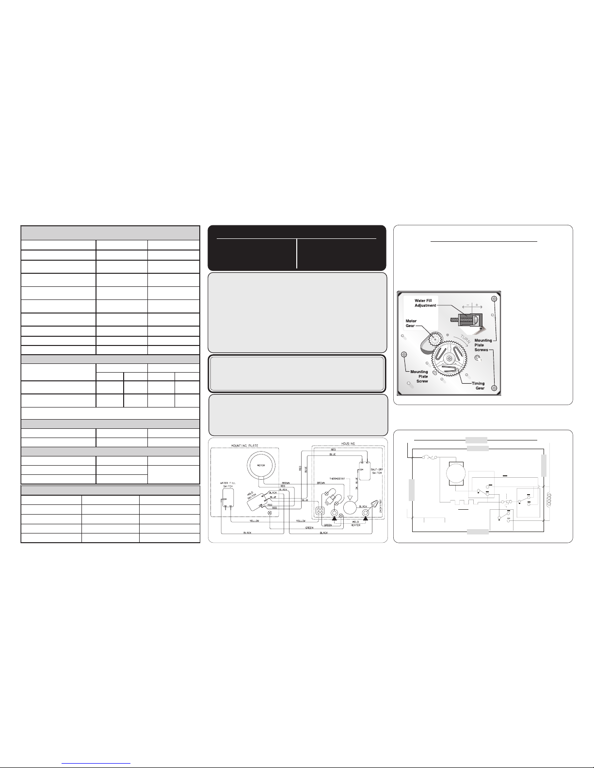
Test Cycling
Remove cover by inserting screwdriver in notch at bottom and prying
cover from housing. Use screwdriver to rotate motor gear
counterclockwise until
Holding Switch
circuit is completed. All
components of ice maker should function to complete the cycle.
Water Fill Volume
The water fill adjustment
screw will change the fill
time. One full turn is
equal to 20cc (.68 oz.).
The correct fill is 95 to
105cc (3.2 to 3.6 oz.).
When a water valve is
replaced, the fill volume
must be checked.
CAUTION: All electrical parts and wiring must be shielded
from torch flame. Do not allow torch to contact insulation; it
will char at 200°F and flash ignite (burn) at 500°F. Excessive
heat will distort the plastic liner.
SERVICE DATA SHEET
IMPORTANT SAFETY NOTICE
The information provided herein is designed to assist qualified repair
personnel only. Untrained persons should not attempt to make
repairs due to the possibility of electrical shock. Disconnect power
cord before servicing.
IMPORTANT
If any green grounding wires are moved during servicing, they
must be returned to their original position and properly secured.
ATADECNAMROFREP
GNITTESLORTNOCTNIOP-DIMTASGNINEPOROODONDNADAOLON
nuRnoitcudnIronuRroticapaCtneibmA)C°81(
F°56tneibmA)C°23(F°09
emiTgnitarepO%53ot52%55ot54
erutarepmeTrezeerFF°8ot°2
C°31-ot°71-
F°5ot°0
C°51-ot°81-
eru
tarepmeTerutaregirfeRF°04ot°53
C°4ot°2
F°04ot°53
C°4ot°2
(erusserPediSwoL
)ni-tuc
gisp61ot8
aPk011ot55
gisp61ot8
aPk011ot55
(erusserPediSwoL
)tuo-tuc
gisp4ot1
aPk82ot7
gisp4ot1
aPk82ot7
(erusserPediShgiH
)elcycfo3/1tsaL
gisp021ot011
aPk728ot857
gisp571ot051
aPk7021ot4301
)elcycfo3/1tsaL(egattaW581ot041581ot041
)gninnuR(spmA6.1o
t1.16.1ot1.1
egatloVesaB)xaMCAV721(CAV511)xaMCAV721(CAV511
SNOITACIFICEPSTSORFED
eziStenibaC
tatsomrehTretaeH
ni-tuCtuo-tuCsttaWsmhO
'12&'81
F°52
C°4-
F°74
C°8
57353
'71&'51,'
41
F°52
C°4-
F°74
C°8
52314
emiTnuRrosserpmoCfosruoH01yrevEsetuniM03tsorfeD-remiTlacinahceM
emiTnuRrosserpmoCfosruoH27-6yrevEsetun
iM42oTpUtsorfeD)CDA(remiTcinortcelE
ROTOMNAFRESNEDNOC
sttaWMPRspmA
3.2tfahSetisoppOWC0011gninnuR51.
SNOITACIFICEPSREKAMECI
lacirtcelE)xaMCAV721(CAV511ztreH06
tatsomrehT)C°9(F°84tasnepO)C°9-(F°51tasesolC
eriwe
gnarOhtiwsledoM
)C8.21-(F69.8taesolc
egattaWretaeH561
STANDARD - AUTOMATIC
DEFROST TOP FREEZER
MODELS (R134a)
P/N: 240379018
NOTE: Some products come equipped with an Electronic
Defrost Control. To initiate defrost, depress the fresh food light
switch 5 times in 6 seconds (light bulb must be working). To
terminate defrost, depress the fresh food light switch 5 times
in 6 seconds.
POWER
ICE MAKER
ICE MAKER
I
CE MAKER
ICE MAKER
WATER VALVE
LINE
THERMAL
CUT-OUT
HOLD
SW IT CH
THERMOSTAT
SHUT-OFF
SWITCH
WATER FI LL
SWITCH
MOLD HEATER
MOL D
MOUN TING
PLATE
MOT O R
NEUTRAL
BLK
BLK
BLK
BLK
BLU
LT. BL U
LT. B LU
BRN
RED
GRN / YE L
GRN / YE L
RED
YEL
YEL
YEL
P-3
P-1
P-2
P-4
(some models)
ORANGE (some models)
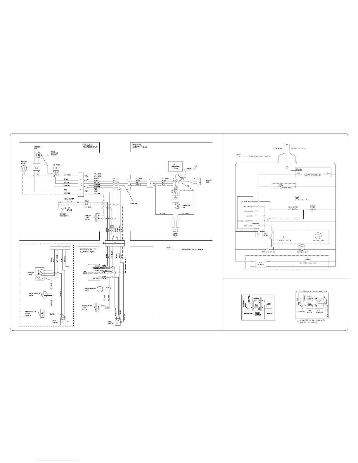
Pictorial Schematic
Ladder Schematic
COMPRESSOR WIRING
Induction Run Compressor with Relay
 Loading...