

Frigidaire FRS093LW11, FRS123LW11, FRS123LW13, FRS123LW10, FRS093LC13 Installation Manual
...
Choosing the installation site
Precautions for Installation
Installation at the following sites may cause problems. Ifyou must inevitably install
the unit at one of these sites, please consult your local distributor beforehand:
1. Sites with machine oil.
2. Sites with a high concentration of salinity, such as coastal areas.
3. Sites with sulfuric gas, such as hot water springs.
4. Sites with high frequency equipment, such as wireless equipment, welding
machines and medical installations.
5. Sites with flammable gases or volatile material.
6. Sites with special environmental conditions.
7. Laundry rooms.
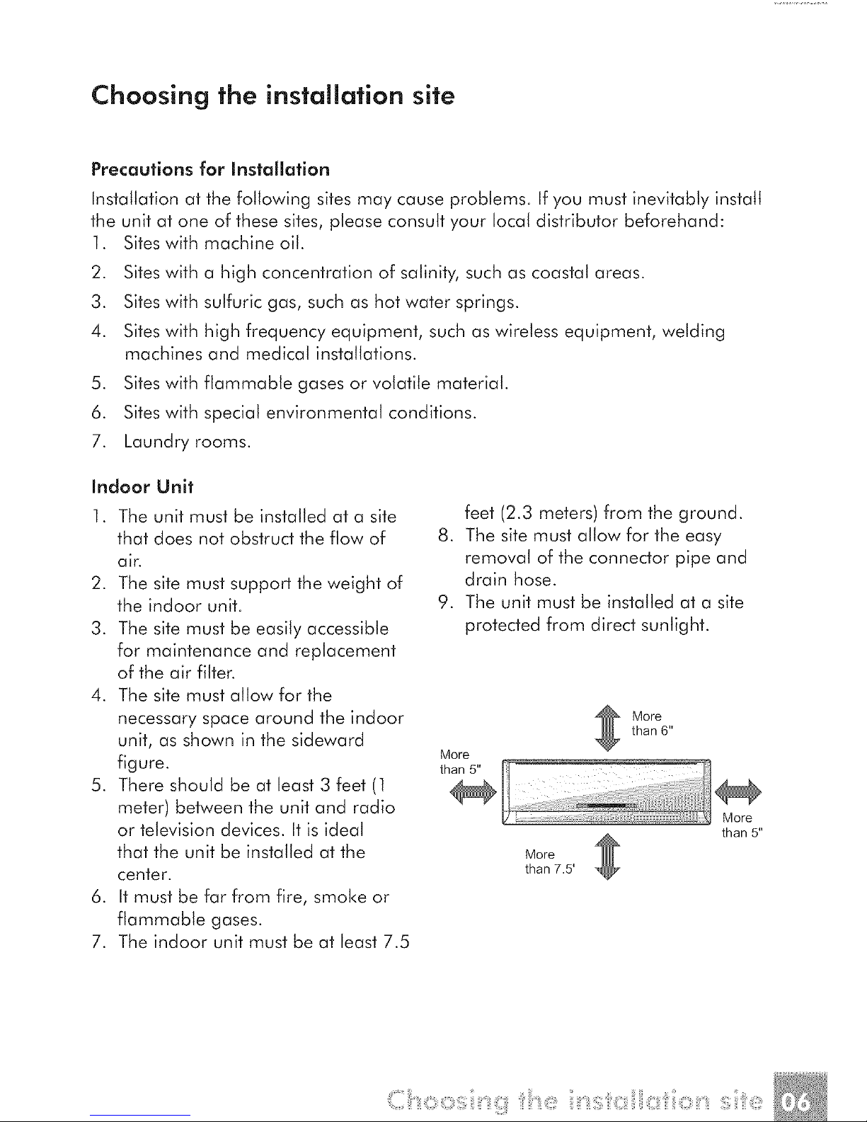
Indoor Unit
1. The unit must be installed at a site
that does not obstruct the flow of
air.
2. The site must support the weight of
the indoor unit.
3. The site must be easily accessible
for maintenance and replacement
of the air filter.
4. The site must allow for the
necessary space around the indoor
unit, as shown in the sideward
figure.
5. There should be at least 3 feet (1
meter) between the unit and radio
or television devices. It is ideal
that the unit be installed at the
center.
6. It must be far from fire, smoke or
flammable gases.
7. The indoor unit must be at least 7.5
feet (2.3 meters) from the ground.
8. The site must allow for the easy
removal of the connector pipe and
drain hose.
9. The unit must be installed at a site
protected from direct sunlight.
More
than 5"
More
than 6"
More
than 7.5'
More
than 5"
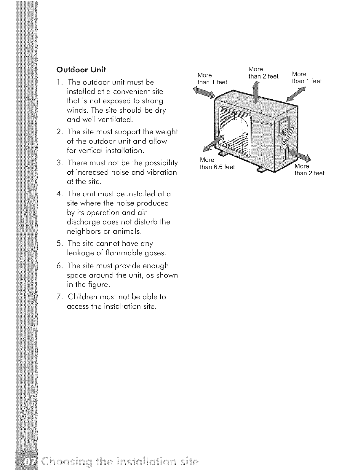
Outdoor Unit
. The outdoor unit must be
installed at a convenient site
that is not exposed to strong
winds. The site should be dry
and well ventilated.
2. The site must support the weight
of the outdoor unit and allow
for vertical installation.
3. There must not be the possibility
of increased noise and vibration
at the site.
4. The unit must be installed at a
site where the noise produced
by its operation and air
discharge does not disturb the
neighbors or animals.
5. The site cannot have any
leakage of flammable gases.
6. The site must provide enough
space around the unit, as shown
in the figure.
7. Children must not be able to
access the installation site.
More
than 1 feet
More
than 6.6 feet
More
than 2 feet
More
than 1 feet
More
than 2 feet
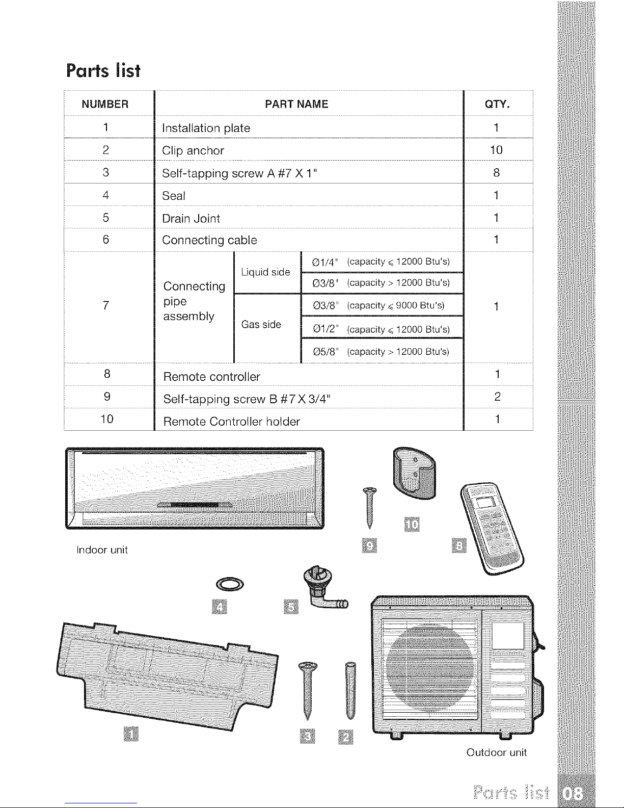
Parts list
NUMBER PART NAME QTY.
1 Installation plate 1
2 Clip anchor 10
3 Self-tapping screw A #7 X 1" 8
4 Seal 1
5 Drain Joint 1
6 Connecting cable 1
_1/4" (capacity _<12000 Btu's
Liquidside
Connecting O3/8" (capacity > 12000 Btu's
7 pipe O3/8" (capacity_<9000Btu's) 1
assembly Gas side Q1/2" (capacity _<12000 Btu's
O5/8'* (capacity > 12000 Btu's)
8 Remote controller 1
9 Self-tapping screw B #7 X 3/4" 2
10 Remote Controller holder 1
Indoor unit
O
Outdoor unit
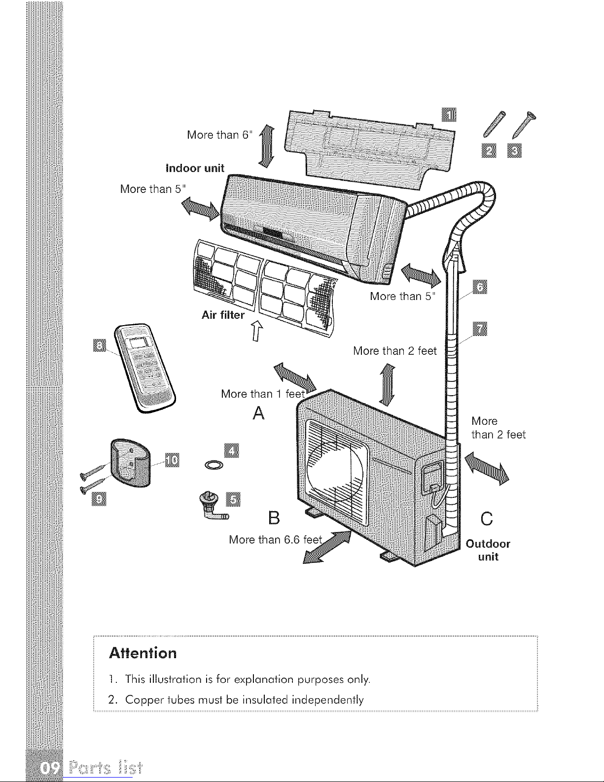
Morethan6"
Indoorunit
Morethan5"
Air filter
More than 1 feet
A
More than 2 feet
More
than 2 feet
B C
More than 6.6 feet Outdoor
unit
Attention
]. This illustration is for explanation purposes onJy.
2. Copper tubes must be insulated independently
indoor unit installation
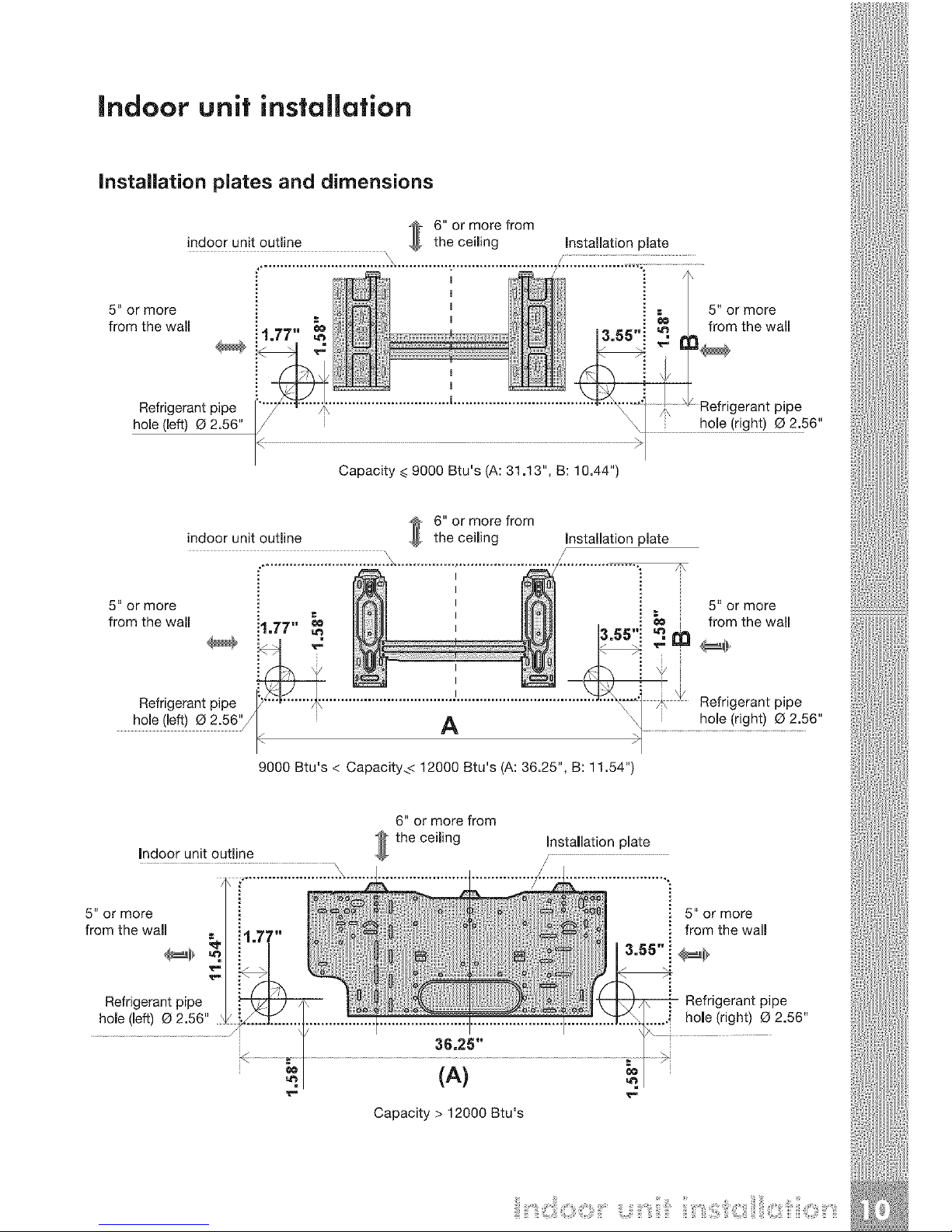
Installation plates and dimensions
6" or more from
indoor unit outline the ceiming Installation plate
................................. .X............... ,.......................... .....
_ ,
5" or more i E . 5" or more
from the wall i I 77" _ _/ ...... _ I from the wall
Refrigerantpipe I_°_'"a ...............................'.................................. Refrigerantpipe
hole(left) 02.56" \1 h°!e!r[£ht) _2:56"
::;:::; _::;0Btu:iA ::i: ; ;; 44 1 _*/
6" or more from
indoor unit outline the ceiling Installation plate
::::::::::::::::::::::::::::........................................./............
5" or more ._ 5" or more
from the wall i4 TT" _ . _ from the wall
hole (left) O 2.56'_< i A \/ hole (right) O 2.56"
9000 Btu's < Capacity_< 12000 Btu's (A: 36.25", B: 11.54")
Indoor unit outline
6" or more from
the ceiling
Installation plate
5" or more
from the wall
Refrigerant pipe
hole (left) (3 2.56"
Capacity > 12000 Btu's
5" or more
from the wall
Refrigerant pipe
......i hole (right) (_ 2.56"
i
Indoorunitoutline
5"ormore
fromthewall =
Refrigerantpipe
hole{left)Q2.56"
6"ormorefrom
the ceiling Installation plate
/ ...........................................................................
(B)
5" or more
from the wall
Refrigerant pipe
hole (right) O 2.56"
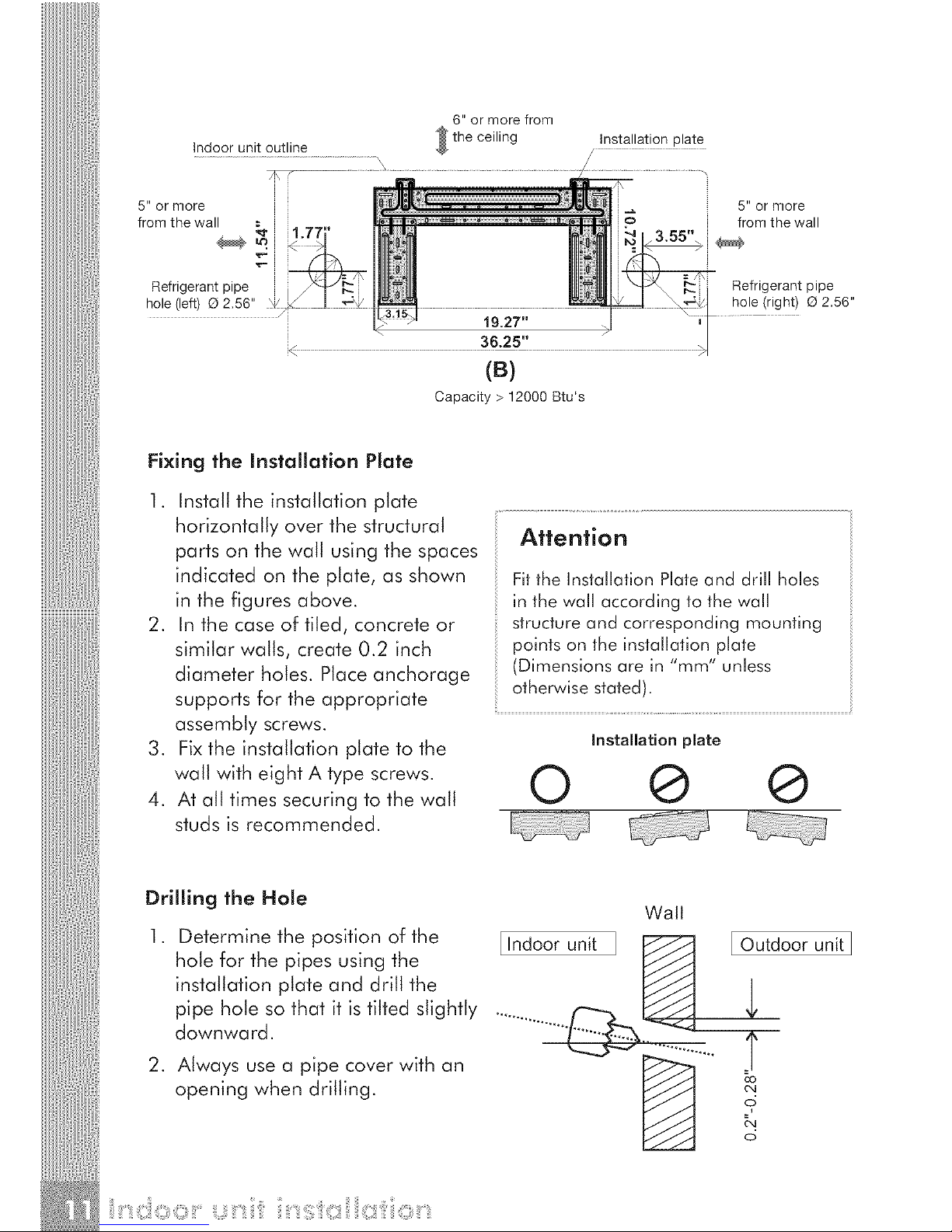
Capacity > 12000 Btu's
Fixing the Installation Plate
1. Install the installation plate
horizontally over the structural
parts on the wall using the spaces
indicated on the plate, as shown
in the figures above.
2. In the case of tiled, concrete or
similar walls, create 0.2 inch
diameter holes. Place anchorage
supports for the appropriate
assembly screws.
3. Fixthe installation plate to the
wall with eight A type screws.
4. At all times securing to the wall
studs is recommended.
Attention
Fitthe Installation Plateand drill holes
in the wall according to thewall
structureand corresponding mounting
points on the installation plate
(Dimensionsare in "mm" unless
otherwisestated).
installation plate
© @ ®
Drilling the Hole
.
Determine the position of the
hole for the pipes using the
installation plate and drill the
pipe hole so that it is tilted slightly
downward.
2. Always use a pipe cover with an
opening when drilling.
Wall
I Indoor unit [ Outdoor unit]
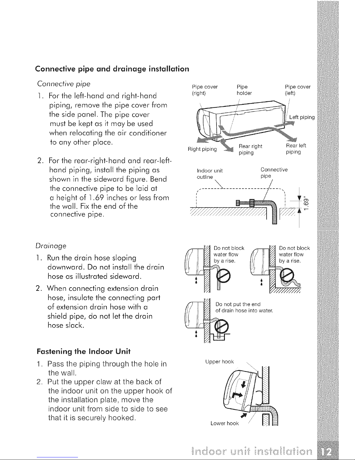
Connective pipe and drainage installation
Connective pipe
1. For the left-hand and right-hand
piping, remove the pipe cover from
the side panel. The pipe cover
must be kept as it may be used
when relocating the air conditioner
to any other place.
.
For the rear-right-hand and rear-left-
hand piping, install the piping as
shown in the sideward figure. Bend
the connective pipe to be laid at
a height of ].69 inches or less from
the wall. Fixthe end of the
connective pipe.
Pipe cover Pipe Pipe cover
(right) holder (left)
piping
Ri ht DiDina _ Rear right Rear left
gm ptpmg _ piping_ piping
Indoor unit Connective
outline pipe
ssssssssss_
Drainage
1. Runthe drain hose sloping
downward. Do not install the drain
hose as illustrated sideward.
.
When connecting extension drain
hose, insulate the connecting part
of extension drain hose with a
shield pipe, do not let the drain
hose slack.
Fastening the indoor Unit
1. Pass the piping through the hole in
the wall.
2. Put the upper claw at the back of
the indoor unit on the upper hook of
the installation plate, move the
indoor unit from side to side to see
that it is securely hooked.
Do not block _[_ Do not block
water.flow [// [I I_/_ water.flow
Do not put the end
of drain hose into water.
Upper hook \
Lower hook
 Loading...