

Frigidaire FGMC2765KBA, FGMC2765KBB, FGMC2765KWA, FGMC2765KWB, FGMC3065KBA Installation Guide
...Page 1
iNSTALLATiON AND SERVICE MUST BE PERFORMED BY A QUALiFiED iNSTALLER.
Canada
iMPORTANT: SAVE FOR LOCAL ELECTRICAL iNSPECTOR'S USE.
READ AND SAVE THESE iNSTRUCTiONS FOR FUTURE REFERENCE.
FOR YOUR SAFETY: Do not store or use gasoline or other flammable vapors
and liquids in the vicinity of this or any other appliance.
Your new wall oven has been designed to fit a limited variety of cutout sizes to make the
job of installing easier. The first step of your installation should be to measure your current
cutout dimensions and compare them to the cutout dimensions chart below for your
model. You may find little or no cabinet work is necessary.
Do not remove spacers (if equipped) on the side wails and/or on the back of the built=
in oven. These spacers center the oven in the space provided. The oven must be centered to prevent
excess heat buildup that may result in heat damage or fire.
United States
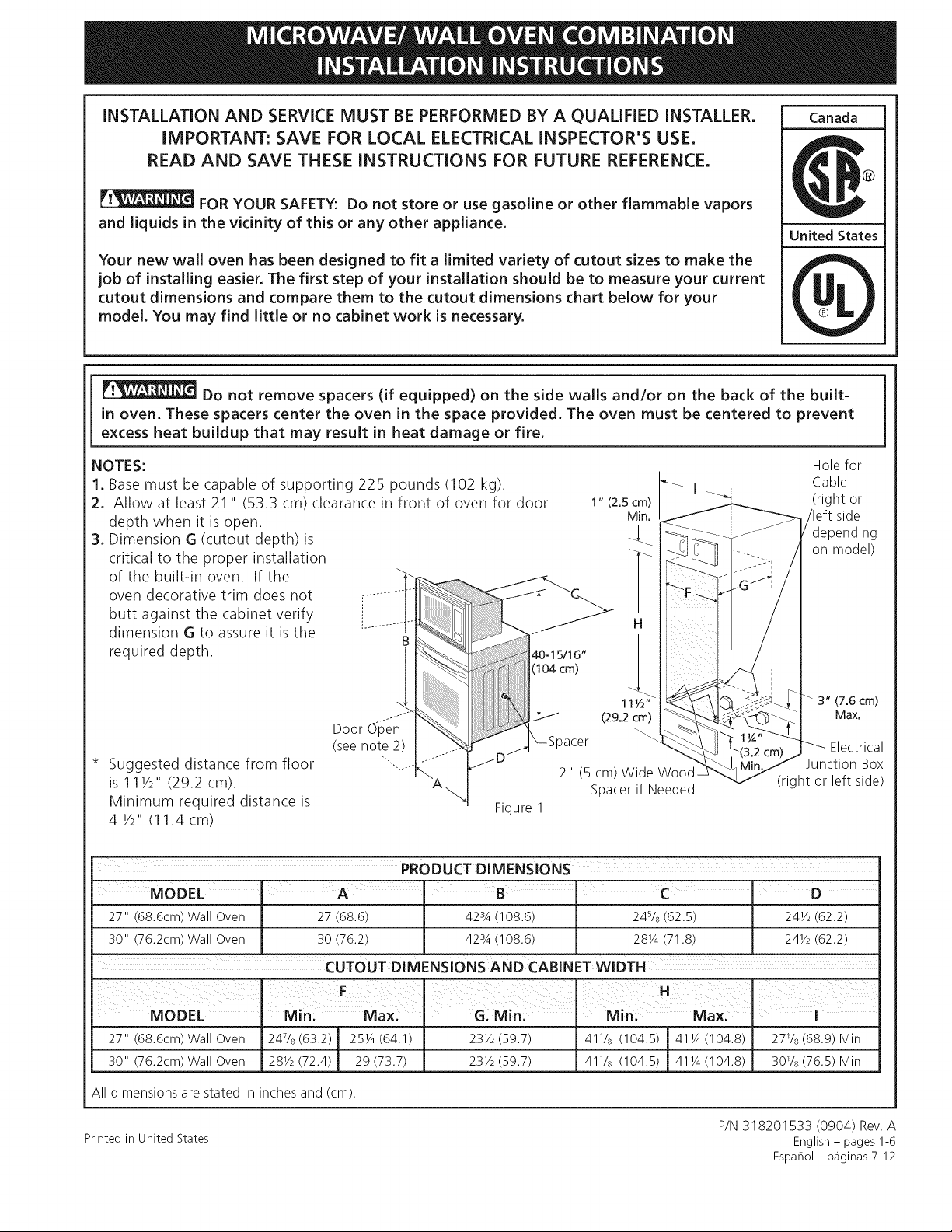
NOTES:
1. Base must be capable of supporting 225 pounds (102 kg).
2. Allow at least 21 " (53.3 cm) clearance in front of oven for door
depth when it is open.
3. Dimension G (cutout depth)is
critical to the proper installation
of the built-in oven. If the
oven decorative trim does not ............
butt against the cabinet verify
dimension G to assure it is the _..........
required depth, s
11Y2" 3" (7.6 cm)
(29.2 cm) Max.
2" (5 cm)Wide
Spacerif Needed
(right or left side)
Suggested distance from floor
is 111/2" (29.2 cm).
Minimum required distance is
4 1/2"(11.4 cm)
n
Door
(see note 2)
Figure 1
MODEL A I B C D
27" (68.6cm) Wall Oven 27 (68.6) 423A (108.6) 24s/8 (62.5) 24V2 (62.2)
30" (76.2cm)Wall Oven 30 (76.2) 428A (108.6) 28Y4 (71.8) 24V2 (62.2)
CUTOUT DIMENSIONS AND CABINET WIDTH
F_ _ _ H
I
Holefor
Cable
(right or
side
depending
on model)
Electrical
Junction Box
27"/686cm/Wa,,Oven1247,8/632/! 25 4/641/123 2/597/141 ,8/1045/41 4/1048/127 ,s/689/Min
30"/762cm/Wa,,Oven128 2/724//29/737/I 23 /597/141 , /1045/41 /1048/I30 , /765/Min
All dimensions are stated in inches and (cm).
Printed in United States
P/N 318201533 (0904) Rev. A
English - pages 1-6
Espahol- p_iginas 7-12
Page 2
important Notes to the Installer
1. Read all instructions contained in these installation
instructions before installing the combination oven.
2. Remove all packing material from the oven
compartments before connecting the electrical supply
to the wall oven.
3. Observe all governing codes and ordinances.
4. Be sure to leave these instructions with the consumer.
5. Oven door may be removed to facilitate installation.
6. THiS COMBINATION OVEN IS NOT APPROVED FOR
STACKABLE OR SIDE-BY=SIDEINSTALLATION.
important Note to the Consumer
Keep these instructions with your Owner's Guide for
future reference. Do not discard oven removal tools found
in the literature bag.
IMPORTANT SAFETY
INSTRUCTIONS
• Be sure your combination oven is installed and
grounded properly by a qualified installer or
service technician.
• This wall oven must be electrically grounded in
accordance with local codes or, in their absence,
with the National Electrical Code ANSI/NFPA
No.70- latest edition in United Sates, or with CSA
Standard C22.1, Canadian Electrical Code, Part 1,
in Canada.
Stepping, leaning or sitting on the
door of this wall oven can result in serious injuries
and can also cause damage to the wall oven.
2. Electrical Requirements
This appliance must be supplied with the proper voltage
and frequency, and connected to an individual, properly
grounded branch circuit, protected by a circuit breaker
or fuse. To know the circuit breaker or fuse required
by your model, see the serial plate to find the wattage
consumption and refer to table A to get the circuit
breaker or fuse amperage.
ApplianCe Protedi0n, ApPliance Protection
Rating Watts Circuit Rating Watts. Circuit
240V Recommended 208V Recommended
Lessthan4800W 20A Lessthan4100W 20A
4800W- 7200W 30A 4100W- 6200W 30A
7200W- g600W 40A 6200W- 8300W 40A
9600Wand + B0A 8300Wand + B0A
Table A
Observe all governing codes and local ordinances
1.A 3-wire or 4-wire single phase 120/240 or 120/208
Volt, 60 Hz AC only electrical supply is required on a
separate circuit fused on both sides of the line (red
and black wires). A time-delay fuse or circuit breaker is
recommended. DO NOT fuse neutral (white wire). Only
certain cooktop models may be installed over certain
built-in electric oven models. Approved cooktops and
built-in ovens are listed by the MFG ID number (see the
insert sheet included in the literature package).
NOTE: Wire sizes and connections must conform with
the fuse size and rating of the appliance in accordance
with the American National Electrical Code ANSI/NFPA
No. 70-latest edition, or with Canadian CSA Standard
C22.1, Canadian Electrical Code, Part 1, and local codes
and ordinances.
• Never use your wall oven for warming or heating
the room. Prolonged use of the wall oven without
adequate ventilation can be dangerous.
The electrical power to the oven must
be shut off while line connections are being made.
Failure to do so could result in serious injury or
death,
1. Carpentry
Refer to figure 1 for the dimensions applicable to
your appliance, and the space necessary to receive the
combination oven. The oven support surface may be
solid plywood or similar material, however the surface
must be leveled from side to side and from front to rear.
An extension cord should not be used
with this appliance. Such use may result in a fire,
electrical shock, or other personal injury, If you need
a longer power cord you can purchase a 10' (3 m) power
cord kit #903056-9010 by calling the Service Center.
2. These appliances should be connected to the fused
disconnect (or circuit breaker) box through flexible
armored or nonmetallic sheathed cable. The flexible
armored cable extending from the appliance should
be connected directly to the junction box. The
junction box should be located as shown in Figure
1 or Figure 2 and with as much slack as possible
remaining in the cable between the box and the
appliance, so it can be moved if servicing isever
necessary.
3. A suitable strain relief must be provided to attach
the flexible armored cable to the junction box.
2
Page 3
Electrical Shock Hazard
• Electrical ground is required on this appliance.
• Do not connect to the electrical supply until
appliance is permanently grounded.
• Disconnect power to the junction box before
making the electrical connection.
• This appliance must be connected to a grounded,
metallic, permanent wiring system, or a
grounding connector should be connected to
the grounding terminal or wire lead on the
appliance.
• Do not use a gas supply line for grounding the
appliance.
Failure to do any of the above could result in a
fire, personal injury or electrical shock.
In cold weather shipping and storage
conditions, make sure that oven is in final location
at least three (3) hours before switching on power.
Switching on power while oven is still cold may damage
the oven controls.
3. Electrical connection
It is the responsibility and obligation of the consumer to
contact a qualified installer to assure that the electrical
installation is adequate and is in conformance with the
National Electrical Code ANSI/NFPA No. 70-latest edition,
or with CSA Standard C22.1, Canadian Electrical Code,
Part 1, and local codes and ordinances.
Risk of electrical shock (Failure to
heed this warning may result in electrocution or
other serious injury.) This appliance is equipped
with copper lead wire. If connection is made to
aluminum house wiring, use only connectors that
are approved for joining copper and aluminum wire
in accordance with the National Electrical Code
and local code and ordinances. When installing
connectors having screws which bear directly on
the steel and/or aluminum flexible conduit, do no
tighten screws sufficiently to damage the flexible
conduit. Do not over bend or excessively distort
flexible conduit to avoid separation of convolutions
en exposure of internal wires.
DO NOT ground to a gas supply pipe. DO NOT connect
to electrical power supply until appliance is permanently
grounded. Connect the ground wire before turning on
the power.
(If your appliance is equipped with a
white neutral conductor.)
This appliance is manufactured with a white neutral
power supply and a frame connected copper wire.
The frame is grounded by connection of grounding
lead to neutral lead at the termination of the
conduit, if used in USA, in a new branch circuit
installation (1996 NEC), mobile home, recreational
vehicles, where local code do not permit grounding
trough the neutral (white) wire or in Canada,
disconnect the white and green lead from each
other and use ground lead to ground unit in
accordance with local codes, connect neutral lead
to branch circuit=neutral conductor in usual manner
see Figure 4. If your appliance is to be connected
to a 3 wire grounded junction box (US only),
where local code permit connecting the appliance=
grounding conductor to the neutral (white) see
Figure 3.
NOTE TO ELECTRICIAN: The armored cable leads
supplied with the appliance are UL-recognized for
connection to larger gauge household wiring. The
insulation of the leads is rated at temperatures much
higher than temperature rating of household wiring. The
current carrying capacity of the conductor is governed by
the temperature rating of the insulation around the wire,
rather than the wire gauge alone.
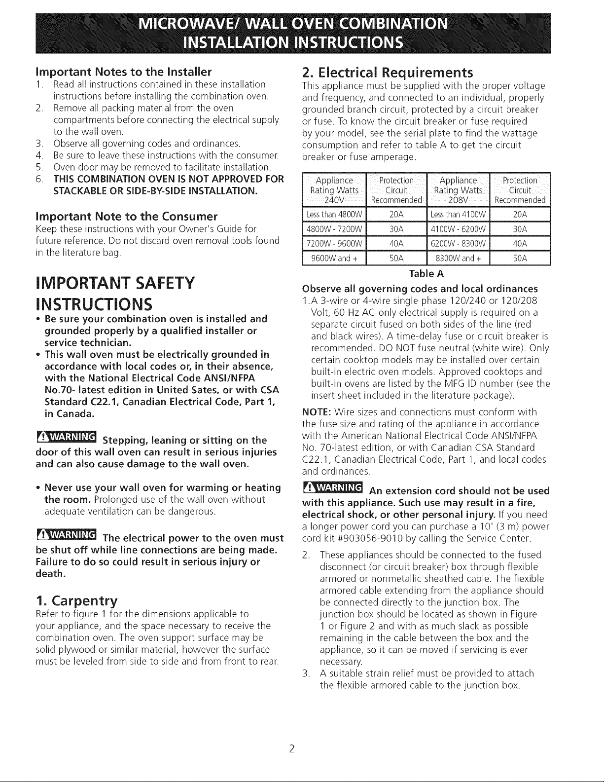
Where local codes permit connecting the appliance=
grounding conductor to the neutral (white) wire
(US Only) (see figure 3):
1. Disconnect the power supply.
2. In the junction box:
connect appliance and power supply cable wires as
shown in Figure 3.
Cable from Power Supply
White Wire _-----..J /
(Neutral) _ .... _--------z/_,B) acK
Red --._"
_1 14-----J uncti°n
?BrCl.unodrGWi:enWJeh.et _Sttodr _i°ini_:ita,'istedt
.,,.jr_" -:::_._.._-_ / _/_ VVIres-
....... Box
__' _White Wire
Cable from appliance
Figure 3
3-WIRE GROUNDED JUNCTION BOX
3
Page 4
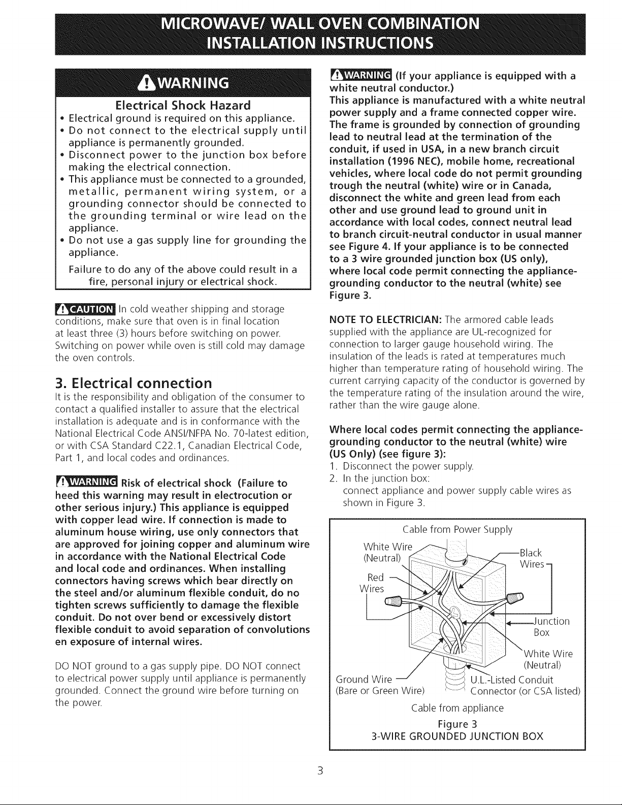
If oven is used in a new branch circuit installation
(1996 NEC), mobile home, recreational vehicle,
or where local codes DO NOT permit grounding
through the neutral (white) wire, the appliance
frame MUST NOT be connected to the neutral wire
of the 4-wire electrical system. (see figure 4):
1. Disconnect the power supply.
2. Separate the green (or bare copper) and white
appliance cable wires.
3. In the junction box:
connect appliance and power supply cable wires as
shown in Figure 4.
Cable from Power Supply
Ground Wire i _--_
hite Wire
_,,__ Black
Ground Wire __) !(Bare or Green ___
Wire) / ----t
Junction Box ........
......... U.L.-Listed Conduit
Wiris
White Wire
Connector (or CSA
Cable from appliance listed)
Figure 4
4-WIRE GROUNDED JUNCTION BOX
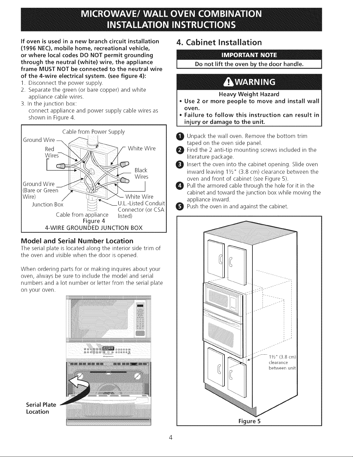
4. Cabinet Installation
Do not lift the oven by the door handle.
Heavy Weight Hazard
• Use 2 or more people to move and install wall
oven,
• Failure to follow this instruction can result in
injury or damage to the unit.
O Unpack the wall oven. Remove the bottom trim
taped on the oven side panel.
_t Find the 2 anti-tip mounting screws included in the
literature package.
_I Insert the oven into the cabinet opening. Slide oven
inward leaving 11/2'` (3.8 cm) clearance between the
oven and front of cabinet (see Figure 5).
Pull the armored cable through the hole for it in the
cabinet and toward the junction box while moving the
appliance inward.
_I Push the oven in and against the cabinet.
Model and Serial Number Location
The serial plate is located along the interior side trim of
the oven and visible when the door is opened.
When ordering parts for or making inquires about your
oven, always be sure to include the model and serial
numbers and a lot number or letter from the serial plate
on your oven.
Serial Plate
Location
...... lY2" (3.8 cm)
clearance
between unit
Figure 5
4
Page 5

Olnstall the Anti-tip Mounting Screws
The wall oven can tip when the door
is open. The anti-tip mounting screws supplied
with the wall oven must be installed to prevent
tipping of the wall oven and injury to persons.
A. The mounting holes in the side trims may be used
as a template to locate the appliance mounting screw
holes (see figure 6).
B. Use the two screws supplied to fix the appliance to
the cabinet.
O Install the Bottom Trim
Placethe top of the bottom trim over the side trim
tabs on each side of the oven below the oven door
and fix it using the 2 screws supplied in the mounting
holes located on each side trim below the oven frame
(seeFigure 7).
Bottom Trim
:: L. /
.......... . _ .....................
Figure 6
Screws
supplied
Figure 7
Page 6

5, Leveling the Wall Oven
1. Install an oven rack in the center of the upper oven
(see Figure 8).
2. Place a level on the rack. Take 2 readings with the
level placed diagonally in one direction and then the
other. Use wood shims under the wall oven to level if
necessary.
3. Repeat in the lower oven if you have a double cavity
wall oven. If the level indicates that the rack is not
level, use wood shims to reach a compromise for
both ovens.
Figure 8
7. Checking Operation
Your model is equipped with an Electronic Oven
Control. Each of the functions has been factory checked
before shipping. However, it is suggested that you verify
the operation of the electronic oven controls once more.
Refer to the Use and Care Guide for operation.
,
Remove all items from the inside of the oven.
2.
Turn on the power to the oven (Refer to your Use &
Care Guide.)
,
Verify the operation of the electronic oven controls:
Bake - Verify that this function makes the oven hot.
20 seconds after turning oven on, open the door and
you should feel heat coming from the oven.
Broil - When the oven is set to BROIL,the upper
element in the oven should become red.
Before You Call for Service
Read the Before You Call for Service Checklist and
operating instructions in your Use and Care Guide.
It may save you time and expense. The list includes
common occurrences that are not the result of defective
workmanship or materials in this appliance.
A cooling fan inside the upper rear part
above the oven (some models) provides
cooling of the oven electrical and
electronic components. If the oven has
been operating at high temperatures, the
fan will continue to run after the oven is
turned off.
Refer to your Use and Care Guide for service phone
numbers.
6
Page 7

LA INSTALACK)N Y EL SERVICIO DEBEN SER EFECTUADOS POR UN Canada
INSTALADOR CALIFICADO. IMPORTANTE: GUARDE ESTAS INSTRUCCIONES
PARA USO DEL iNSPECTOR LOCAL DE ELECTRICIDAD. LEA Y GUARDE ESTAS
INSTRUCCIONES PARA REFERENCIA FUTURA.
llr,__ PARA SU SEGURIDAD: No almacen_ ni utilice gasolina u otros vapores y liquidos
inflamables en la proximidad de este o de cualquier otro artefacto. EstadosUnidos
El primer paso para su instalaci6n debe de ser el de medir las dimensiones de la apertura
y compararlas con las que se indican en el cuadro de dimensiones del hueco de la figura 1.
Posiblemente encontrar_ que alg_n trabajo de carpinteria ser_ necesario.
No quite los separadores de los muros laterales o/y de la parte posterior del homo
empotrado. Estos espadadores centran el homo en el espacio provisto. El homo debe estar centrado para
prevenir una concentraci6n excesiva de calor que podria resultar en daEos pot el calor o un incendio.
NOTAS:
1. La base debe poder sostener 255 libras (102kg).
2. Deje por Io menos 21 " (53.3 cm) de espacio libre para la
profundidad de la puerta cuando esta abierta.
3. La dimension G (profundidad
del corte) est,1primordial para
instalar
1" (2.5 cm) Cable
Min. derechao
__ izquierda,
Orificio
parael
modelo)
correctamente el homo i.........iii
de pared. Si el adorno del
]__ - segQnel
contra el armario verifique
si la dimension G est_qen
conformidad con la dimension
5c11_" (29 I?i 3" (7.6 cm)
requerida.
x_ Espaciador
Espaciador de de empalme
Madera de 2" (derecha o
(5 cm) de izquierda)
ancho, si es
necesario
Distancia sugerida desde el
suelo es 111/2" (29.2 cm).
La distancia minima requerida
es 41/2" (11.4 cm).
(veala ,
Puerta -:-ii,_i!,_i
Figura 1
DIMENSIONES DEL APARATO
MODELO A B - C ' D
27" (68.6cm) 27 (68.6) 423A (108.6) 245/8 (62.5) 241/2 (62.2)
30" (76,2cm) 30 (76.2) 423A (108.6) 281/4(71.8) 241/2 (62.2)
DIMENSIONES DEL HUECO Y ANCHURA DEL ARMARIO
Max.
a electrica
27"/68.6cm/Wa,,Oveo1247,8/63.2/251/4/64.1/I 231/,/59.7/ /10 .5/1 11/4/10 .8/I27Vs(68.9)Min
30"(76.2crn)WallOven [281/2(72.4) 29(73.7) 1 231/2(59.7) ] 41V_(104.5)1411/4(104.8)] 30Vs(76.5)Min
Todas las dimensiones sedan en pulgadas (cm).
Impreso en los Estados Unidos
P/N 318201533 (0904) Rev. A
English - pages 1-6
Espahol- p_iginas 7-12
Page 8

Notas importantes para el instalador
1. Leatodas lasinstruccionescontenidas en este manual
antes de instalarel combinacion microondas/ homo de
pared.
2. Saquetodo el material usado enel embalaje del
compartimiento del homo antes de conectar el suministro
electrico o de gasa la estufa.
3. Observetodos loscodigos y reglamentos pertinentes.
4. Dejeestas instrucciones con el consumidor.
5. La puerta del homo se puede retirar para facilitar la
instalacion.
6. ESTECOMBINACION MICROONDAS / HORNO DE
PAREDNO ESTAAPROBADO PARA LA INSTALACION
APILABLE O DE LADO A LADO,
Nota importante ai consumidor
Conserve estas instrucciones y el manual del usuario para
referencia futura. No tirar las herramientas para retirar el
homo incluidas en la bolsa de la literatura.
INSTRUCCIONES
IMPORTANTES DE SEGURIDAD
• Asegurese de que su combinacion microondas /
homo de pared sea instalado y puesto a tierra de
forma apropiada pot un instalador calificado o pot
un tecnico de servicio,
• Este homo de pared debe set electricarnente puesto
a tierra de acuerdo con los c6digos locales o, en su
ausencia, con el C6digo Electrico National ANSi/
NFPA No. 70-ultirna edici6n en los Estados Unidos, o
el C6digo Electrico Canadiense CSA Standard C22,1,
Part 1, en Canada,
I1_ Pisar, apoyarse, o sentarse sobre la
puerta de este homo de pared puede
causar serias lesiones y da_os al homo de pared,
• Nunca use su homo de pared para calentar una
habitation. El uso prolongado de la estufa sin la
ventilacion adecuada puede set peligroso.
I1_ La corriente electrica al homo debe
estar apagada rnientras se hacen las
conexiones de lineas, Si no se apaga, da_os serios o la
rnuerte podrian resultar,
1. Carpinteria
Consulte la Figura 1 para conocer lasdimensiones pertinentes
al modelo de su homo y alespacio necesarioen el que poner
el homo. Lasuperficie donde seva a apoyar el homo debe
de set de madera contrachapada solida u otto material similar
y,sobre todo, la superficie tiene que estar a nivel, de lado a
lado, y deatr_ishaciaadelante.
2. Requerirnientos Electricos
Se debe proveer el voltaje y la frecuencia apropiados a
este electrodom_stico, y conectarse a un circuito individual
correctamente puesto atierra, protegido por un interruptor o
un fusible. Paraconocer el interruptor o fusible que requiere
su modelo, vea la placa serial para encontrar la consumaci0n
del vatiaje y refierase al cuadro A paraencontrar elamperaje
del interruptor o fusible.
Grados de ' Se reComienda
Vatios del una
electrodom_stico protecci6n al
240v - circuito
Menosde4800W 20A
4800W-7200W 30A
7200W-g600W 40A
9600Wand+ 50A
Table A
Observe todos los codigos que gobiernan y ordenanzas
locales
1. Un cable de 3 o 4 alambres monof_isico 120/240 o
120/208 voltios, 60 hertzios esla 0nica fuente el_ctrica que
requiere en uncircuito separado enambos lados dela linea
(alambre negro y alambre rojo) (se recomienda un fusible
o un interruptor de retraso de tiempo). No funda a cable
neutro (alambre blanco). Se debe de tener precauci6n al
combinar un homo de pared y una cubierta, re%rase a
la placa de seria de cada uno de los aparatos.
NOTA: Los tamahos y las conexiones del alambre deben
conformarse con el tamaho del fusible y el grado de la
aplicaci6n de acuerdo con el c6digo El@ctrico Nacional
Americano ANSI/NFPA No. 70- ultima edici6n, o con
el est_indar CSA canadiense C22.1 , c6digo el@ctrico
canadiense, parte 1, y c6digos y ordenanzas locales.
No se debera usar extensiones para
enchufar este electrodomestico, Esto podria causar
un incendio, choque electrico u otto tipo de daffo
personal, Si usted necesita un cable mas largo, puede
ordernar un cable de 10" kit 903056-9010 Ilamando al
centro de Servicio.
2. Esteelectrodom#stico debe conectarse a la caja de
fusibles (o de cortocircuito), pot medio de un cable
blindado flexible o un cable con forro no met_ilico. El
cable blindado flexible que va desde el electrodom_stico
debe de estar conectado directamente a la caja de
empalme. Lacaja de empalme debe de estar Iocalizada
en el lugar que se indica en la Figura 1 o 2, dejando
tanto exceso de cable como sea posible entre lacaja y el
electrodom_stico, de forma que asiel electrodom_stico
se pueda mover flicilmente, si fuera necesario para hacer
una reparaciOn.
3. Se debe de usar un conector que reduzca la tirantez de
una forma adecuada para unir el cable blindado flexible
a la caja de empalme.
Giados de se recomienda
Vatios del ' una
electrodom_stico protecci6n al
208V - circuito
Menosde4100W 20A
4100W- 6200W 30A
6200W- 8300W 40A
8300Wand + 50A
8
Page 9

Riesgo de choque ei6ctrico
• Una puesta a tierra se requiere en este aparato.
• No Io conecte a la corriente eJ6ctrica hasta que el
aparato haya sido puesto a tierra.
• Desconecte la corriente eJectrica a la caja de
empaJmes antes de hater la conexi6n electrica.
• Este aparato debe estar conectado con un
sistema de aiambres puesto en tierra, met_lico
y permanente o un conector de puesta a tierra
debe conectarse aJterminal de puesta a tierra o el
aJambre conductor en aJaparato.
• No utiJice el suministro de gas para hacer la puesta
a tierra.
La faJta de cuaJquiera de las instrucciones
mencionadas podria resuJtar en un incendio, choque
eiectrico o lesiones personaJes.
En cuanto alas condiciones de
despacho y almacenamiento en el invierno, aseg0rese de
que el homo Ilegue a su destino final como minimo tres
(3) horas antes de encenderlo. Si se enciende el homo
cuando a0n est,1frio, se pueden dahar los controles.
4. Conexi6n electrica
El usuario tiene la responsabilidad personal y obligacion
de utilizar un instalador calificado, para asegurar que la
instalaciOn electrica est,1hacha de forma adecuada y est,1
conforme con el Codigo Electrico Nacional ANSI/NFPA
No. 70-01tima edicion en los Estados Unidos, o el Codigo
Electrico Canadiense CSAStandard C22.1, Part 1, en
Canada
Riesgo de choque el6ctrico
(El no prestar atencion a esta advertencia puede
resultar en electrocuci6n u otras lesiones graves.)
Este electrodom6stico est_ equipado con alambre
de cobre. Si se va a conectar con cableado de
aluminio deJ hogar, utiJizar unicamente conectores
que est_n aprobados para unit cobre y aluminio de
acuerdo al Codigo Nacional Electrico (NEC pot sus
siglas en ingJes) y leyes y codigos locales. AI instalar
conectores con torniJJos que empujen directamente
contra el acero y/o aluminio deJ conducto flexible,
no apretar los tornillos suficientemente que dahen
eJconducto flexible. No dobJar de mas o deformar
el conducto flexible para evitar separar el espiral y
descubrir los alambres internos.
NO conecte el alambre puesto a tierra a una tuberia
de suministro de gas. NO conecte el suministro de
energia el_ctrica hasta que el electrodom_stico haya sido
permanentemente puesto atierra. Conecte el alambre
de puesto a tierra antes de enchufar por primera vez el
electrodom_stico.
(Si su electrodom6stico est_ equipado
con un conductor neutro bJanco.)
Este electrodom6stico est_ fabricado con un
suministro el6ctrico neutro bJanco y un alambre de
cobre conectado al armazon. El armazon esta puesto
a tierra pot un enlace de la conexion a tierra con la
conexion del neutro al final de la linea el6ctrica, si es
usado en los estados unidos una nueva instalaci6n
de circuito de bifurcacion (1996 NEC), casa rodante,
vehiculos recreacionales, o donde los codigos locales
no permitan poner a tierra mediante el neutro
(bJanco) o en Canada, desconectar la conexion
blanca de la verde y utiJizar la conexion a tierra para
poner a tierra la unidad de acuerdo a los codigos
locales, conectar el neutro al circuito de bifurcation-
conductor neutro de manera usual. Vet Figura 4. Si
su electrodom6stico va a set conectado a una caja de
conexion puesta a tierra de 3 cables (en los estados
unidos solamente), donde los codigos locales
permitan conectar el conductor de poner a tierra=
electrodom6stico con el neutro (bJanco) vet Figura 3.
NOTA AL ELECTRICISTA: Los conductores de cable
blindados provistos con este artefacto son aprobados por
UL para la conexiOn al alambrado de casa de un calibre
mayor. El aislamiento de los conductores est,1calificado
para temperaturas m_isaltas que las del alambrado de
la casa. La capacidad de corriente del conductor est,1
gobernada por la calificaci6n de la temperatura del
aislamiento alrededor del alambre en vez de solamente el
calibre del alambre.
Donde los codigos locales permitan conectar el
conductor de puesta a tierra del electrodom6stico al
neutral (blanco) (Solamente en los Estados Unidos)
(vea figura 3):
1. Desconecte el suministro el_ctrico.
2. En el caja de juntas: conectar el aparato y los cables
residenciales como semuestra en la figura 3.
Cable desde el suministro de energia
Alambre _---_
desnudo _ :_..... _"--1
/_Alambre
egros
. de
\',{.... empalmes
I \ Alambre
Alambre verd
o desnudo _ _::!:;!_
Cable de la estufa (o CSA)
Figura 3 - CAJA DE EMPALMES
DE 3 ALAMBRES PUESTAA TIERRA
desnudo
Conductor de
uni6n listado-UL
9
Page 10

Si el horno se usa en una instalacion de circuito de
ramal nuevo (1996 NEC), en una casa rodante, en
un vehiculo para recreacion o si los codigos locales
NO permiten la conexion a tierra a traves del cable
neutral (blanco), el armazon del electrodom6stico
NO TIENE QUE estar conectado al alambre neutro
del sistema el6ctrico de 4 alambres. (ver figura 4):
1. Desconecte el suministro el_ctrico
2. Separe el alambre verde (o cobre desnudo) y el
alambre blanco del electrodom_stico.
3. En el caja de juntas: conectar el aparato y los cables
residenciales como se muestra en la figura 4.
Cable desde el suministro de energia
Alambre
desnudo,_
Alambre _
Alambre
/blanco
(ojos
Alambre
Alambre
s
verde o
desnudo
,Alambre blanco
Caja de
empalmes
Conductor de
uni6n listado-UL
Cable de la estufa (o CSA)
Figura 4- CAJA DE EMPALMES
DE 4 ALAMBRES PUESTA A TIERRA
5. Instalaci6n del Gabinete
IMPORTANTE
No levante el homo pot la manija de la puerta.
Peligro de Peso Pesado
* Use 2 personas o m_s para mover e instalar el homo
de pared.
* Si no cumple con esta instrucci6n, puede resultar
en lesiones personales o dafios al horno de pared
ODesembalar el homo de pared. Extraer la guarnici0n
inferior y los 2 tornillos unidos con cinta al panel lateral
del homo.
OBuscar los tornillos que se incluyen en el paquete de
literatura.
Olnsertar el homo en la abertura del gabinete. Deslizar el
homo hacia dentro dejando 11/2"(3,8 cm) de espacio
libre entre el homo y la parte delantera del gabinete
(ver la Figura 5).
OEmpujar el cable blindado a trav_s del orificio del
gabinete y hacia la caja de paso mientras se desliza el
accesorio hacia adentro.
_Empujar el homo hacia adentro yen contra del
gabinete
Ubicaci6n del numero de modelo y de serie
La placa con el n0mero de serie est,1ubicada en la
guarnici6n interior lateral del homo y se puede ver cuando
se abre la puerta.
Cuando haga pedidos
de repuestos o
solicite informaci6n
con respecto a su
homo, est@siempre
seguro de incluir el
n0mero de modelo y
de serie y el n0mero ._,
o letra del Iote de la
placa de serie de su
homo.
La placa de
serie est_
ubicada aqu{.
I........... i
-" 1 1/2" (3.8 cm)
/ ....
distancia entre la unidad
y el gabinete
10
Figura 5
Page 11

0 Instaladon de los tornillos de montado
El homo de pared puede inclinarse
cuando la puerta esta abierta, Los soportes de
montaje que vienen con el homo de pared deben
de estar ajustadas al armario y al aparato para
evitar que el homo de pared se incline y ocasione
quemaduras graves,
A. Los barrenos en las molduras laterales pueden
ser usadas como guia para Iocalizar los tornillos de
montado de la unidad (figura 6).
B. Use los dos tornillos proporcionados para colocar
la unidad en la cabina.
O Instalad6n de la Guarnid6n Inferior:
Colocar la parte superior de la guarniciOn inferior
sobre las leng0etas laterales del homo, debajo de
la puerta del homo, y fijarlas usando los 2 tornillos
provistos con los orificios de montaje ubicados a cada
lado del marco del homo (ver la Figura 7).
Guarnici6n
Inferior
Tornillos de montado
Figura 6
Tornillos
provistos
Figura 7
11
Page 12

6. Asegurese de que el horno de
pared esta a nivel
1. Instale una rejilla al centro del homo superior (vea la
Figura 8).
2. Ponga un nivel pot encima de la rejilla. Lea 2 veces,
una vez con el nivel a la posici6n de lado a lado, y otra
vez de atr_ishacia adelante. Utilice trozo de madera o
cuhas pot debajo del homo de pared para nivelar, si sea
necesario.
3. Vuelve aempezar en el homo inferior. Siel nivel muestra
que la rejilla no esta a nivel, utilice trozo de madera o
cuhas para componer ambos hornos.
7. Verificacion dei funcionamiento
Su modelo est,1equipado con un Control Electronico
de Horno. Cada una de lasfunciones ha sido controlada
en f_ibrica antes del despacho. Sin embargo, le sugerimos
verificar el funcionamiento de los controles electrOnicos
una vez m_is.Consulte la Guia de Uso y Cuidado para
ver el funcionamiento del horno.
1. Extraer todos los elementos de la parte interior del
horno.
.
Encender el homo (Consular la Guia de Uso y Cuidado.)
3.
Verificar el funcionamiento de los controles electr6nicos
del homo:
Hornear - Verificar que esta funci6n caliente el horno.
Veinte minutos despu_s de encender el homo, abrir la
puerta y ver si se siente que el calor emana desde su
interior.
Asar- Cuando se pone el homo para asar, el
elemento de arriba del homo debe de ponerse rojo.
Antes de ilamar ai servicio
Lea la secciOn Lista de Antes de Ilamar en su Manual del
Usuario. Esto le podr_i ahorrar tiempo y gastos. Esta
lista incluye ocurrencias comunes que no son el resultado
de defectos de materiales o fabricaci6n de este artefacto.
Figura 8
Un ventilador ubicado dentro de la parte
trasera superior arriba del homo (en
algunos modelos) permite la refrigeracibn
de los componentes el_ctricos y
electrbnicos de enfriamiento. Si el homo ha
estado fun¢ionando a altas temperaturas, el
ventilador seguir& funcionando despu_s de
apagar el homo.
Lea la garantia y la informaci6n sobre el servicio en
su Manual del Usuario para obtener el nOmero de
tel@fono gratuito y la direcci6n del servicio.
12
 Loading...