

Frigidaire FPEF4085KFD Installation Instructions Manual
United States
INSTALLATION AND SERVICEMUST BEPERFORMED BY A QUALIFIED INSTALLER.
flammable vapors and liquids in the vicinity of this or any other appliance.
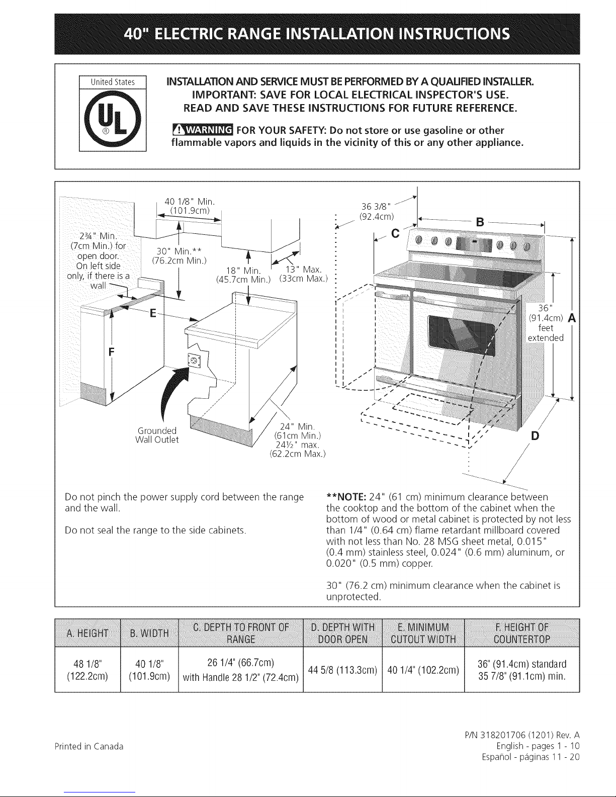
40 1/8" Min.
(101.9cm)
23A'' Min
(7cm Min.) for
open door (76.2cm Min.)
On eft side
30" Min.**
/
on y, if there isa _|
_3_
cwal/
IMPORTANT: SAVE FOR LOCAL ELECTRICAL INSPECTOR'S USE.
READ AND SAVE THESE INSTRUCTIONS FOR FUTURE REFERENCE.
FOR YOUR SAFETY: Do not store or use gasoline or other
18" Min. ' 13" Max.
(45.7cmMin.) (33cm Max.)
36"
(91.4cm) A
Grounded 24" Min.
Wall Outlet (61cm Min.)
241/2" max.
(62.2cm Max.)
Do not pinch the power supply cord between the range
and the wall.
Do not seal the range to the side cabinets.
48 1/8"
(122.2cm)
40 1/8" 26 1/4"(66.7cm)
(101.9cm) with Handle28 1/2" (72.4cm)
**NOTE: 24" (61 cm) minimum clearance between
the cooktop and the bottom of the cabinet when the
bottom of wood or metal cabinet is protected by not less
than 1/4" (0.64 cm) flame retardant millboard covered
with not lessthan No. 28 MSG sheet metal, 0.01 5"
(0.4 ram) stainlesssteel, 0.024" (0.6 mm) aluminum, or
0.020" (0.5 mm) copper.
30" (76.2 cm) minimum clearance when the cabinet is
unprotected.
44 5/8 (113.3cm) 40 1/4" (102.2cm)
36" (91.4cm) standard
35 7/8" (91.1cm) rain.
D
Printed in Canada
P/N318201706 (1201) Rev.A
English - pages 1 - 10
Espa_ol - p_iginas 11 - 20
important Notes to the Installer
1. Read all instructions contained in these installation
instructions before installing range.
2. Remove all packing material from the oven
compartments before connecting the electrical supply
to the range (see "Preparation", page 6).
3. Two anti-tip brackets, located inside the oven cavity
MUST be installed (see "Anti-Tip Bracket Installation",
page 8).
4. Observe all governing codes and ordinances.
5. Be sure to leave these instructions with the consumer.
important Note to the Consumer
Keep these instructions with your owner's guide for future
reference.
IMPORTANT SAFETY
INSTRUCTION
• Be sure your range is installed and grounded
properly by a qualified installer or service
technician.
This range must be electrically grounded in
accordance with local codes or, in their absence,
with the National Electrical Code ANSI/NFPA No.
70--latest edition.
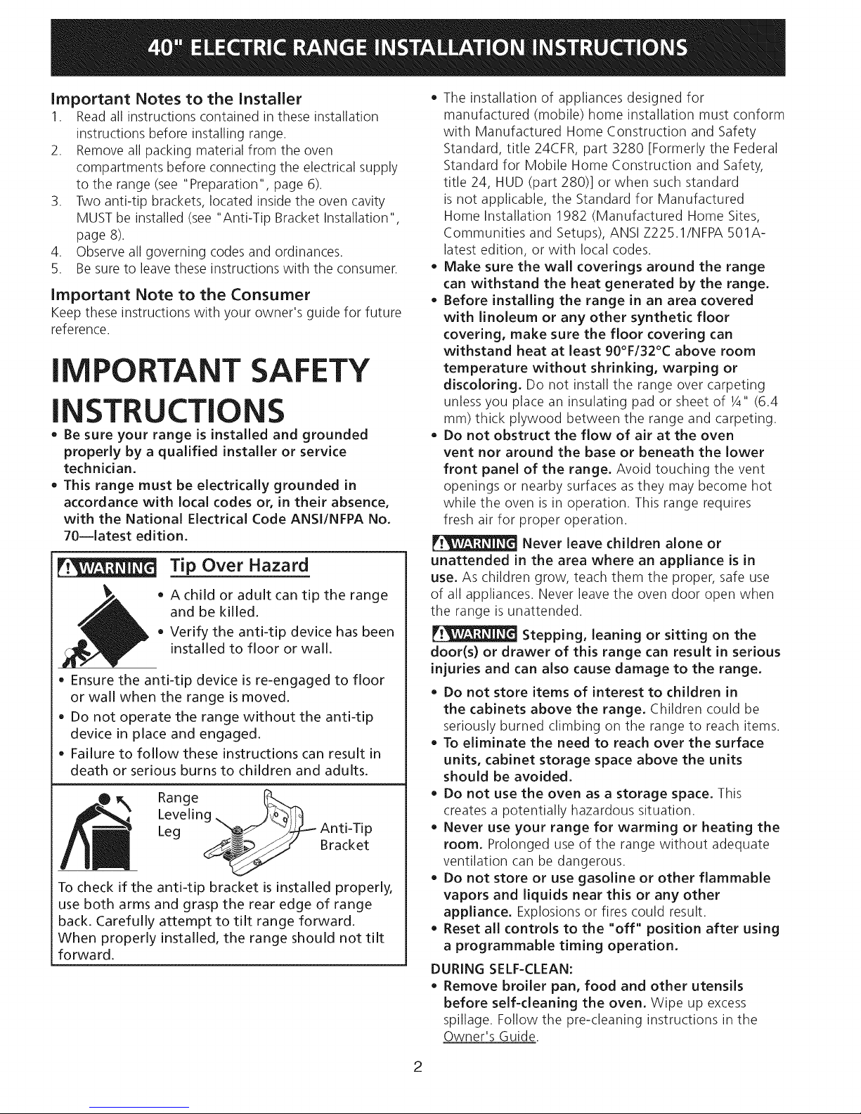
Tip Over Hazard
• Achild or adult can tip the range
and be killed.
• Verify the anti-tip device has been
installed to floor or wall.
Ensure the anti-tip device is re-engaged to floor
or wall when the range is moved.
Do not operate the range without the anti-tip
device in place and engaged.
Failure to follow these instructions can result in
death or serious burns to children and adults.
Leveling
Range __T_
Leg _ Anti-Tip
To check if the antFtip bracket is installed properly,
use both arms and grasp the rear edge of range
back. Carefully attempt to tilt range forward.
When properly installed, the range should not tilt
forward.
/__.__/" Bracket
The installation of appliances designed for
manufactured (mobile) home installation must conform
with Manufactured Home Construction and Safety
Standard, title 24CFR, part 3280 [Formerly the Federal
Standard for Mobile Home Construction and Safety,
title 24, HUD (part 280)] or when such standard
is not applicable, the Standard for Manufactured
Home Installation 1982 (Manufactured Home Sites,
Communities and Setups), ANSI Z225.1/NFPA 501A-
latest edition, or with local codes.
Make sure the wall coverings around the range
can withstand the heat generated by the range.
Before installing the range in an area covered
with linoleum or any other synthetic floor
covering, make sure the floor covering can
withstand heat at least 90°F/32°C above room
temperature without shrinking, warping or
discoloring. Do not install the range over carpeting
unless you place an insulating pad or sheet of 1/4"(6.4
mm) thick plywood between the range and carpeting.
Do not obstruct the flow of air at the oven
vent nor around the base or beneath the lower
front panel of the range. Avoid touching the vent
openings or nearby surfaces as they may become hot
while the oven is in operation. This range requires
fresh air for proper operation.
Never leave children alone or
unattended in the area where an appliance is in
use. As children grow, teach them the proper, safe use
of all appliances. Never leave the oven door open when
the range is unattended.
Stepping, leaning or sitting on the
door(s) or drawer of this range can result in serious
injuries and can also cause damage to the range.
Do not store items of interest to children in
the cabinets above the range. Children could be
seriously burned climbing on the range to reach items.
To eliminate the need to reach over the surface
units, cabinet storage space above the units
should be avoided.
Do not use the oven as a storage space. This
creates a potentially hazardous situation.
Never use your range for warming or heating the
room. Prolonged use of the range without adequate
ventilation can be dangerous.
Do not store or use gasoline or other flammable
vapors and liquids near this or any other
appliance. Explosions or fires could result.
Reset all controls to the "off" position after using
a programmable timing operation.
DURING SELF-CLEAN:
Remove broiler pan, food and other utensils
before self-cleaning the oven. Wipe up excess
spillage. Follow the pre-cleaning instructions in the
Owner's Guide.
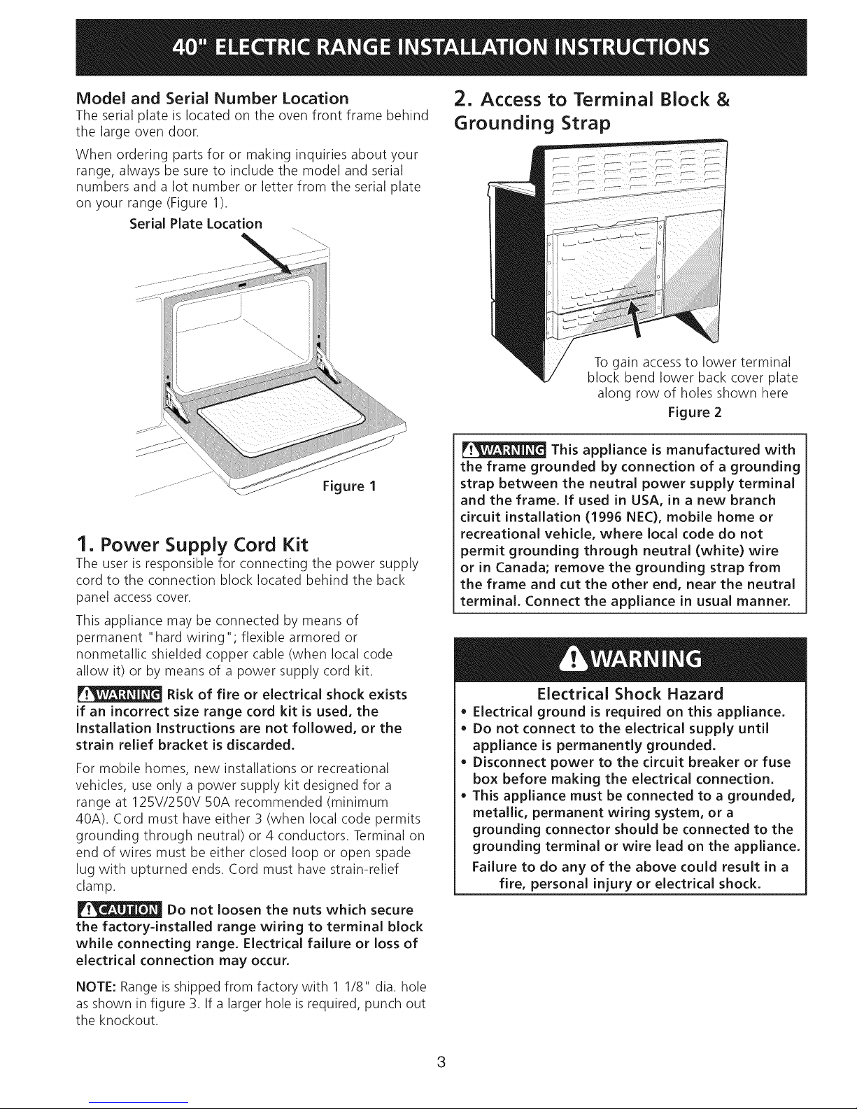
Model and Serial Number Location
The serial plate is located on the oven front frame behind
the large oven door.
When ordering parts for or making inquiries about your
range, always be sure to include the model and serial
numbers and a lot number or letter from the serial plate
on your range (Figure 1).
Serial Plate Location
1. Power Supply Cord Kit
The user is responsible for connecting the power supply
cord to the connection block located behind the back
panel access cover.
This appliance may be connected by means of
permanent "hard wiring"; flexible armored or
nonmetallic shielded copper cable (when local code
allow it) or by means of a power supply cord kit.
Risk of fire or electrical shock exists
if an incorrect size range cord kit is used, the
Installation Instructions are not followed, or the
strain relief bracket is discarded.
For mobile homes, new installations or recreational
vehicles, use only a power supply kit designed for a
range at 125V/250V 50A recommended (minimum
40A). Cord must have either 3 (when local code permits
grounding through neutral) or 4 conductors. Terminal on
end of wires must be either closed loop or open spade
lug with upturned ends. Cord must have strain-relief
clamp.
Do not loosen the nuts which secure
the factory=installed range wiring to terminal block
while connecting range. Electrical failure or loss of
electrical connection may occur.
To gain access to lower terminal
block bend lower back cover plate
along row of holes shown here
Figure 2
This appliance is manufactured with
the frame grounded by connection of a grounding
strap between the neutral power supply terminal
and the frame. If used in USA, in a new branch
circuit installation (1996 NEC), mobile home or
recreational vehicle, where local code do not
permit grounding through neutral (white) wire
or in Canada; remove the grounding strap from
the frame and cut the other end, near the neutral
terminal. Connect the appliance in usual manner.
Electrical Shock Hazard
• Electrical ground is required on this appliance.
• Do not connect to the electrical supply until
appliance is permanently grounded.
• Disconnect power to the circuit breaker or fuse
box before making the electrical connection.
• This appliance must be connected to a grounded,
metallic, permanent wiring system, or a
grounding connector should be connected to the
grounding terminal or wire lead on the appliance.
Failure to do any of the above could result in a
fire, personal injury or electrical shock.
NOTE: Range is shipped from factory with 1 1/8" dia. hole
as shown in figure 3. If a larger hole is required, punch out
the knockout.
3
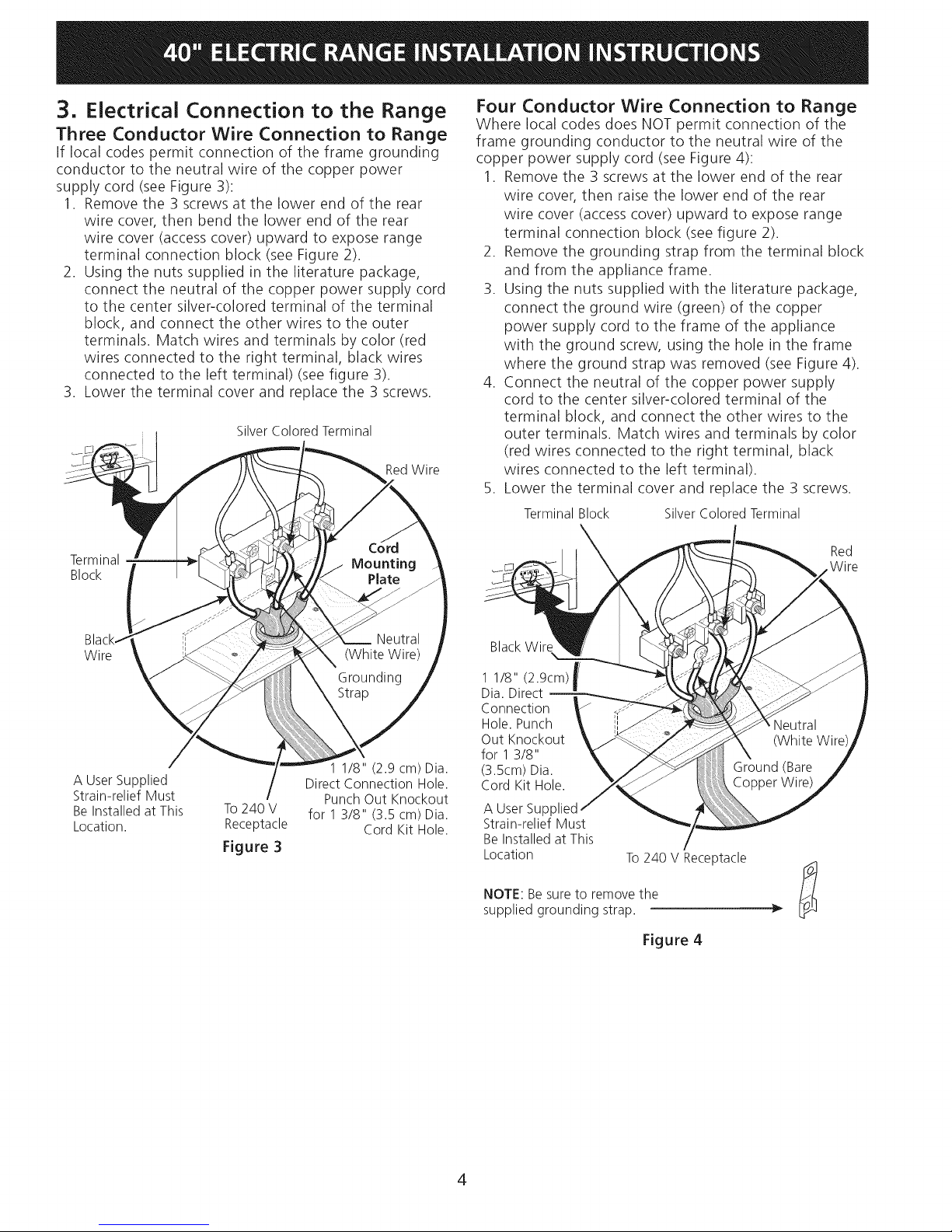
3. Electrical Connection to the Range
Three Conductor Wire Connection to Range
If local codes permit connection of the frame grounding
conductor to the neutral wire of the copper power
supply cord (see Figure 3):
1. Remove the 3 screws at the lower end of the rear
wire cover, then bend the lower end of the rear
wire cover (access cover) upward to expose range
terminal connection block (see Figure 2).
2. Using the nuts supplied in the literature package,
connect the neutral of the copper power supply cord
to the center silver-colored terminal of the terminal
block, and connect the other wires to the outer
terminals. Match wires and terminals by color (red
wires connected to the right terminal, black wires
connected to the left terminal) (see figure 3).
3. Lower the terminal cover and replace the 3 screws.
Silver Colored Terminal
RedWire
Four Conductor Wire Connection to Range
Where local codes does NOT permit connection of the
frame grounding conductor to the neutral wire of the
copper power supply cord (see Figure 4):
1. Remove the 3 screws at the lower end of the rear
wire cover, then raise the lower end of the rear
wire cover (access cover) upward to expose range
terminal connection block (see figure 2).
2. Remove the grounding strap from the terminal block
and from the appliance frame.
3. Using the nuts supplied with the literature package,
connect the ground wire (green) of the copper
power supply cord to the frame of the appliance
with the ground screw, using the hole in the frame
where the ground strap was removed (see Figure 4).
4. Connect the neutral of the copper power supply
cord to the center silver-colored terminal of the
terminal block, and connect the other wires to the
outer terminals. Match wires and terminals by color
(red wires connected to the right terminal, black
wires connected to the left terminal).
5. Lower the terminal cover and replace the 3 screws.
Terminal Block Silver Colored Terminal
Terminal
Block
Wire
A User Supplied
Strain-relief Must
Be Installed at This
Location.
To240 V
Receptacle
Figure 3
1 1/8" (2.9 cm) Dia.
Direct Connection Hole.
Punch Out Knockout
for 1 3/8" (3.5 cm) Dia.
Cord Kit Hole.
BlackWire
1 1/8" (2.9cm) _/
Dia. Direct
II
Connection
Hole.Punch
Out Knockout
for 13/8"
(3.5cm)Dia.
Cord Kit Hole.
A User Supl
Strain-relief Must
Be Installed at This
Location
NOTE: Be sure to remove the
supplied grounding strap.
To 240 V Receptacle
Red
Wire
Figure 4
4
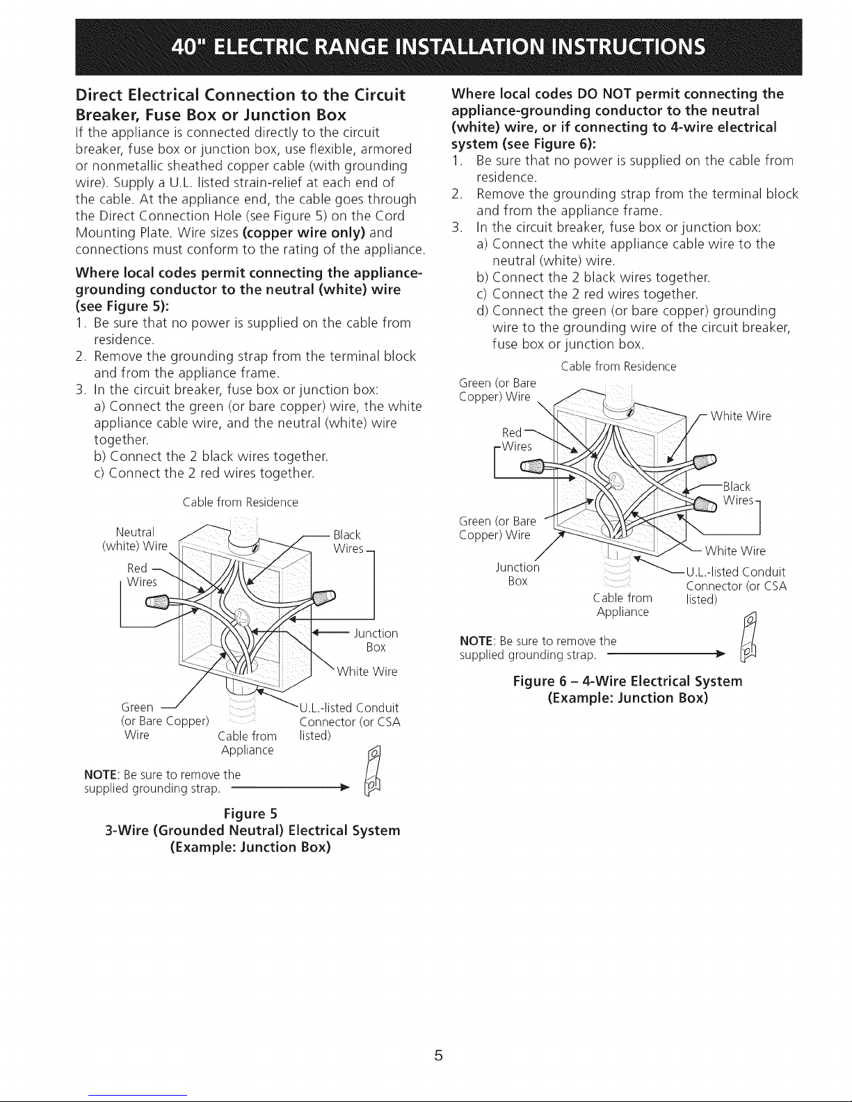
Direct Electrical Connection to the Circuit
Breaker, Fuse Box or Junction Box
If the appliance is connected directly to the circuit
breaker, fuse box or junction box, use flexible, armored
or nonmetallic sheathed copper cable (with grounding
wire). Supply a U.L. listed strain-relief at each end of
the cable. At the appliance end, the cable goes through
the Direct Connection Hole (see Figure 5) on the Cord
Mounting Plate. Wire sizes (copper wire only) and
connections must conform to the rating of the appliance.
Where local codes permit connecting the appliance-
grounding conductor to the neutral (white) wire
(see Figure 5):
1. Be sure that no power is supplied on the cable from
residence.
2. Remove the grounding strap from the terminal block
and from the appliance frame.
3. In the circuit breaker, fuse box or junction box:
a) Connect the green (or bare copper) wire, the white
appliance cable wire, and the neutral (white) wire
together.
b) Connect the 2 black wires together.
c) Connect the 2 red wires together.
Where local codes DO NOT permit connecting the
appliance-grounding conductor to the neutral
(white) wire, or if connecting to 4-wire electrical
system (see Figure 6):
1. Be sure that no power is supplied on the cable from
residence.
2. Remove the grounding strap from the terminal block
and from the appliance frame.
3. In the circuit breaker, fuse box or junction box:
a) Connect the white appliance cable wire to the
neutral (white) wire.
b) Connect the 2 black wires together.
c) Connect the 2 red wires together.
d) Connect the green (or bare copper) grounding
wire to the grounding wire of the circuit breaker,
fuse box or junction box.
Cablefrom Residence
Green(or Bare
Copper)Wire ,
White Wire
Red
Cable from Residence
(W_Ji_!_/_ i__re_ _ X_/_rCeksm
Green U L-listed Conduit
(or BareCopper) : .... Connector(or CSA
Wire Cablefrom listed)
Appliance
NOTE: Be sure to remove the
supplied grounding strap.
Figure 5
3-Wire (Grounded Neutral) Electrical System
(Example: Junction Box)
J_...(( Wires]
Green (or Bare /It _ _L" _ _I'_ /
Copper)Wire _!_ _ \
_ White Wire
Junction ..... _U.L.-listed Conduit
BOX
Connector(or CSA
Cablefrom listed)
NOTE:Besureto removethe
suppliedgrounding strap.
Appliance
Figure 6 - 4-Wire Electrical System
(Example: Junction Box)
5
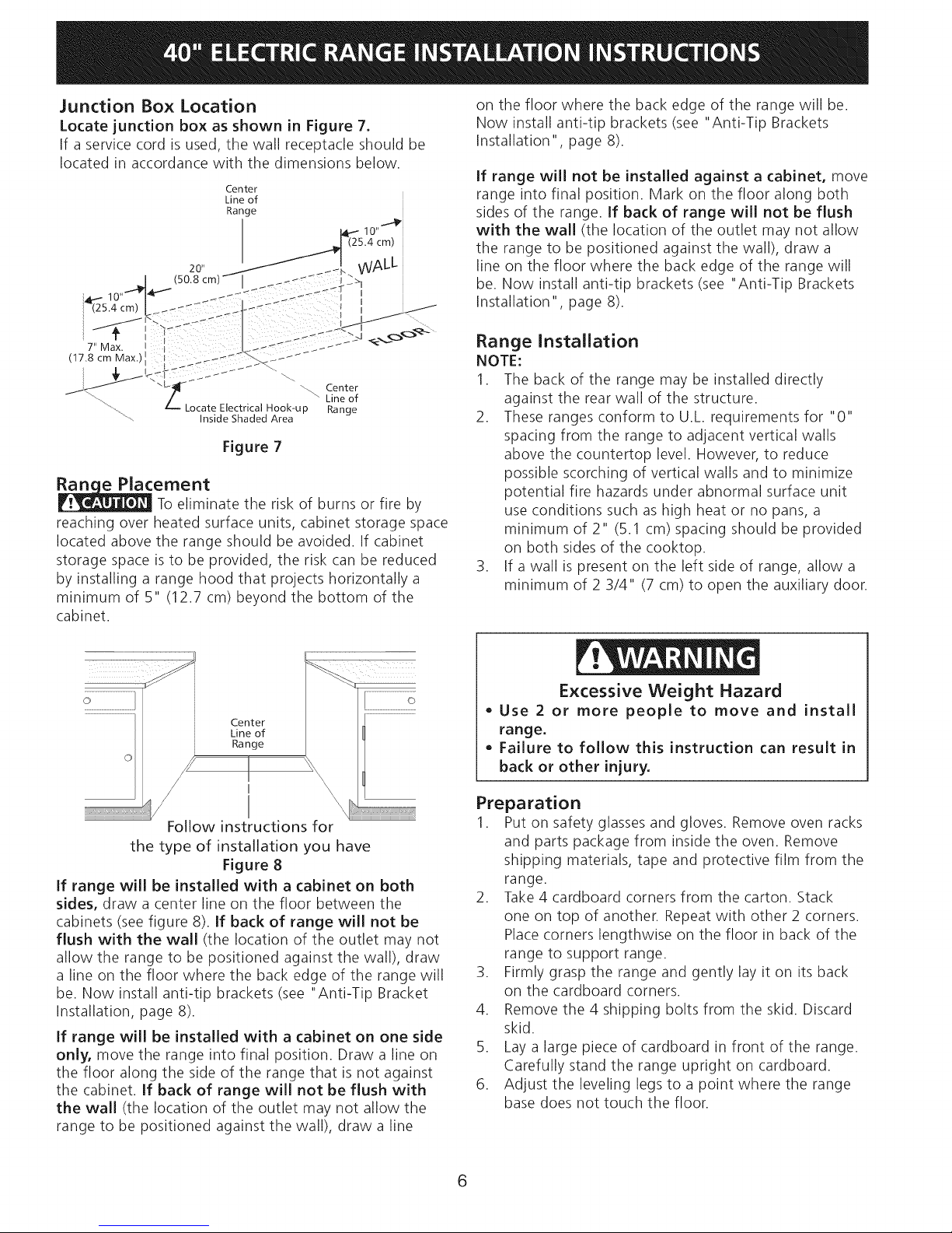
Junction Box Location
Locate junction box as shown in Figure 7.
If a service cord is used, the wall receptacle should be
located in accordance with the dimensions below.
Figure 7
ernent
To eliminate the risk of burns or fire by
reaching over heated surface units, cabinet storage space
located above the range should be avoided. If cabinet
storage space is to be provided, the risk can be reduced
by installing a range hood that projects horizontally a
minimum of 5" (12.7 cm) beyond the bottom of the
cabinet.
on the floor where the back edge of the range will be.
Now install anti-tip brackets (see "Anti-Tip Brackets
Installation" page 8).
If range will not be installed against a cabinet, move
range into final position. Mark on the floor along both
sides of the range. If back of range will not be flush
with the wall (the location of the outlet may not allow
the range to be positioned against the wall), draw a
line on the floor where the back edge of the range will
be. Now install anti-tip brackets (see "Anti-Tip Brackets
Installation", page 8).
Range Installation
NOTE:
1. The back of the range may be installed directly
against the rear wall of the structure.
2. These ranges conform to U.L. requirements for "0"
spacing from the range to adjacent vertical walls
above the countertop level. However, to reduce
possible scorching of vertical walls and to minimize
potential fire hazards under abnormal surface unit
use conditions such as high heat or no pans, a
minimum of 2" (5.1 cm) spacing should be provided
on both sides of the cooktop.
3. If a wall is present on the left side of range, allow a
minimum of 2 3/4" (7 cm) to open the auxiliary door.
Center
Line of
Range
/ I
Follow instructions for
the type of installation you have
Figure 8
If range will be installed with a cabinet on both
sides, draw a center line on the floor between the
cabinets (see figure 8). If back of range will not be
flush with the wall (the location of the outlet may not
allow the range to be positioned against the wall), draw
a line on the floor where the back edge of the range will
be. Now install anti-tip brackets (see "Anti-Tip Bracket
Installation, page 8).
If range will be installed with a cabinet on one side
only, move the range into final position. Draw a line on
the floor along the side of the range that is not against
the cabinet. If back of range will not be flush with
the wall (the location of the outlet may not allow the
range to be positioned against the wall), draw a line
Excessive Weight Hazard
• Use 2 or more people to move and install
range.
• Failure to follow this instruction can result in
back or other injury.
Preparation
1. Put on safety glasses and gloves. Remove oven racks
and parts package from inside the oven. Remove
shipping materials, tape and protective film from the
range.
2. Take 4 cardboard corners from the carton. Stack
one on top of another. Repeat with other 2 corners.
Place corners lengthwise on the floor in back of the
range to support range.
3. Firmly grasp the range and gently lay it on its back
on the cardboard corners.
4. Remove the 4 shipping bolts from the skid. Discard
skid.
5. Lay a large piece of cardboard in front of the range.
Carefully stand the range upright on cardboard.
6. Adjust the leveling legs to a point where the range
base does not touch the floor.
6
 Loading...