

Page 1
IMPORTANT:SAVE FOR LOCAL ELECTRICAL INSPECTOR'S USE.
READ AND SAVE THESE INSTRUCTIONS FOR FUTURE REFERENCE.
OBSERVE ALL GOVERNING CODES AND ORDINANCES.
If the information in this manual is not followed exactly, a fire or explosion may result
causing property damage, personal injury or death.
FOR YOUR SAFETY:
-- Do not store or use gasoline or other flammable vapors and
liquids in the vicinity of this or any other appliance.
-- WHAT TO DO IF YOU SMELL GAS:
• Do not try to light any appliance.
• Do not touch any electrical switch; do not use any phone in your building.
• Immediately call your gas supplier from a neighbor's phone. Follow the gas supplier's
instructions.
• If you cannot reach your gas supplier, call the fire department.
-- Installation and service must be performed by a qualified installer, service agency or the gas
supplier.
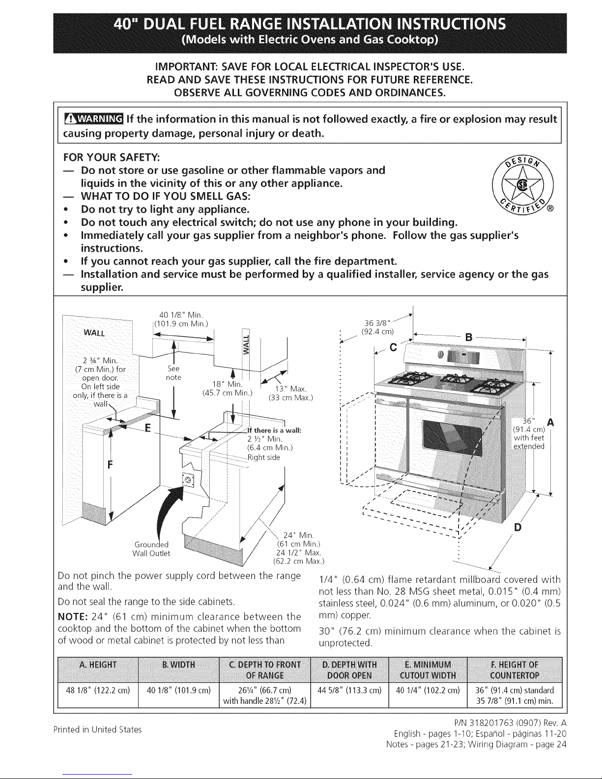
40 1/8" Min.
_(101.9 cm Min.)
WAIL
i (7 cm Min.) for
i open door_
i On left side
0nlyl if there is a
wall,
i
Groun, (61 cm Min.)
Wall Outlet 24 1/2" Max.
See
note
18" Min.
(45.7 cm Min.)
(6.4 cm Min.)
I
I
I
I
I
/"
,/
,/'// 24" Min.
13" Max.
(33 cm Max.)
a wall:
2 Y2" Min.
ht side
(62.2 cm Max.)
Do not pinch the power supply cord between the range
and the wall.
Do not sealthe range to the side cabinets.
NOTE: 24" (61 cm) minimum clearance between the
cooktop and the bottom of the cabinet when the bottom
of wood or metal cabinet is protected by not less than
36 3/8"
(92.4 cm) .÷ .......... B
D
/
1/4" (0.64 cm) flame retardant millboard covered with
not less than No. 28 MSG sheet metal, 0.015" (0.4 mm)
stainless steel, 0.024" (0.6 mm) aluminum, or 0.020" (0.5
ram) copper.
30" (76.2 cm) minimum clearance when the cabinet is
unprotected.
48 1/8" (122.2cm)
40 1/8" (10119cm) 2@/4"(66.7cm) 44 5/8" (113.3 cm) 40 1/4" (102.2 cm)
Printed in United States
with handle 28Y2"(72.4)
36" (91.4cm)standard
35 7/8" (91.1cm) min.
P/N318201763 (0907) Rev.A
English- pages 1-10; Espa_ol- p_Sginas11-20
Notes - pages 21-23; Wiring Diagram - page 24
Page 2
Important Notes to the Installer
1. Read all instructions contained in these installation
instructions before installing range.
2. Remove all packing material from the oven
compartments before connecting the electrical supply
to the range (see "Preparation", page 8).
3. Two anti-tip brackets, located inside the oven cavity MUST
be installed (see "Anti-Tip BracketInstallation", page 8).
4. Observe all governing codes and ordinances.
5. Be sure to leave these instructions with the consumer.
Important Note to the Consumer
Keep these instructions with your owner's guide for future
reference.
IMPORTANT SAFETY
INSTRUCTION
Installation of this range must conform with local codes
or, in the absence of local codes, with the National Fuel
Gas Code ANSI Z223. l-latest edition.
This range has been designed certified by the American
Gas Association. As with any appliance using gas and
generating heat, there are certain safety precautions you
should follow. You will find them in the Use and Care
Guide, read it carefully.
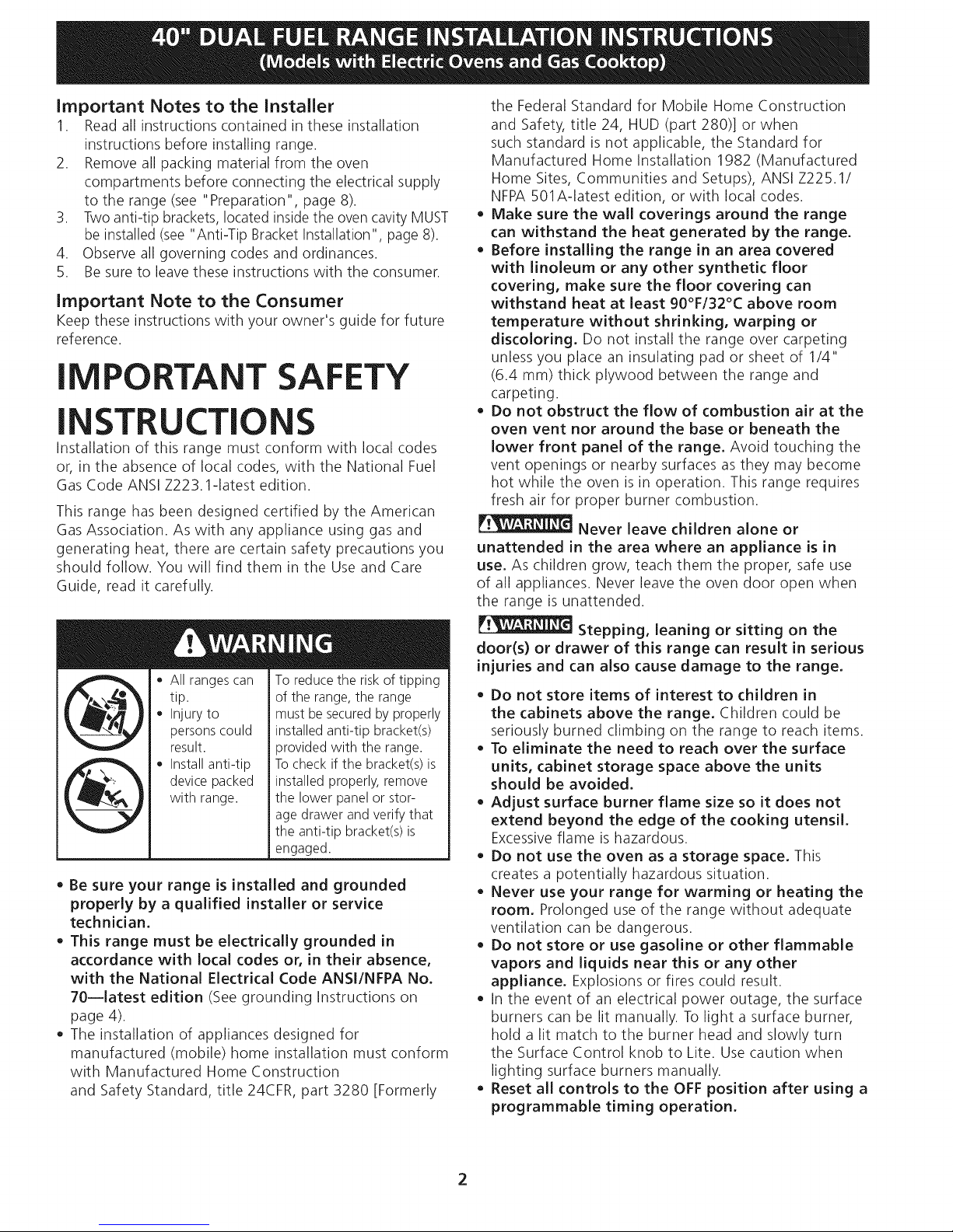
o All ranges can
tip.
Injury to
persons could
result.
Install anti-tip
device packed
with range.
• Be sure your range is installed and grounded
properly by a qualified installer or service
technician.
This range must be electrically grounded in
accordance with local codes or, in their absence,
with the National Electrical Code ANSI/NFPA No.
70--latest edition (See grounding Instructions on
page 4).
The installation of appliances designed for
manufactured (mobile) home installation must conform
with Manufactured Home Construction
and Safety Standard, title 24CFR, part 3280 [Formerly
To reduce the risk of tipping
of the range, the range
must be secured by properly
installed anti-tip bracket(s)
provided with the range.
To check if the bracket(s) is
installed properly, remove
the lower panel or stor-
age drawer and verify that
the anti-tip bracket(s)is
engaged.
the Federal Standard for Mobile Home Construction
and Safety, title 24, HUD (part 280)] or when
such standard is not applicable, the Standard for
Manufactured Home Installation 1982 (Manufactured
Home Sites, Communities and Setups), ANSI Z225.1/
NFPA 501A-latest edition, or with local codes.
Make sure the wall coverings around the range
can withstand the heat generated by the range.
Before installing the range in an area covered
with linoleum or any other synthetic floor
covering, make sure the floor covering can
withstand heat at least 90°F/32°C above room
temperature without shrinking, warping or
discoloring, Do not install the range over carpeting
unless you place an insulating pad or sheet of 1/4"
(6.4 ram) thick plywood between the range and
carpeting.
Do not obstruct the flow of combustion air at the
oven vent nor around the base or beneath the
lower front panel of the range, Avoid touching the
vent openings or nearby surfaces as they may become
hot while the oven is in operation. This range requires
fresh air for proper burner combustion.
Never leave children alone or
unattended in the area where an appliance is in
use, As children grow, teach them the proper, safe use
of all appliances. Never leave the oven door open when
the range is unattended.
Stepping, leaning or sitting on the
door(s) or drawer of this range can result in serious
injuries and can also cause damage to the range.
Do not store items of interest to children in
the cabinets above the range, Children could be
seriously burned climbing on the range to reach items.
To eliminate the need to reach over the surface
units, cabinet storage space above the units
should be avoided,
Adjust surface burner flame size so it does not
extend beyond the edge of the cooking utensil,
Excessiveflame is hazardous.
Do not use the oven as a storage space, This
creates a potentially hazardous situation.
Never use your range for warming or heating the
room, Prolonged use of the range without adequate
ventilation can be dangerous.
Do not store or use gasoline or other flammable
vapors and liquids near this or any other
appliance, Explosions or fires could result.
In the event of an electrical power outage, the surface
burners can be lit manually. To light a surface burner,
hold a lit match to the burner head and slowly turn
the Surface Control knob to Lite. Use caution when
lighting surface burners manually.
Reset all controls to the OFF position after using a
programmable timing operation.
Page 3
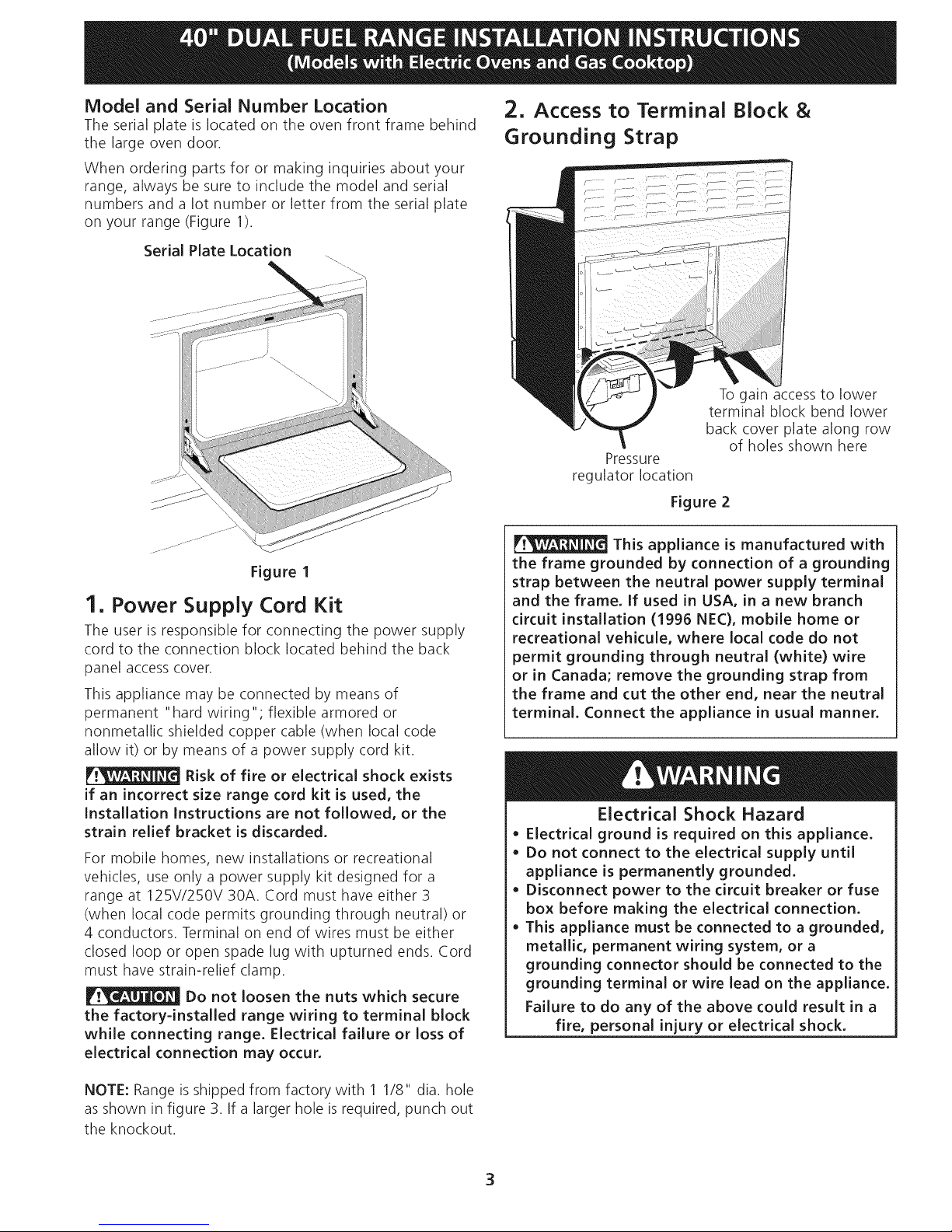
Model and Serial Number Location
Theserialplateislocatedontheovenfrontframebehind
thelargeovendoor.
Whenorderingpartsforormakinginquiriesaboutyour
range,alwaysbesuretoincludethemodelandserial
numbersandalotnumberorletterfromtheserialplate
onyourrange(Figure1).
SerialPlateLocation
Figure 1
1. Power Supply Cord Kit
The user is responsible for connecting the power supply
cord to the connection block located behind the back
panel access cover.
This appliance may be connected by means of
permanent "hard wiring"; flexible armored or
nonmetallic shielded copper cable (when local code
allow it) or by means of a power supply cord kit.
Risk of fire or electrical shock exists
if an incorrect size range cord kit is used, the
Installation Instructions are not followed, or the
strain relief bracket is discarded.
For mobile homes, new installations or recreational
vehicles, use only a power supply kit designed for a
range at 125V/250V 30A. Cord must have either 3
(when local code permits grounding through neutral) or
4 conductors. Terminal on end of wires must be either
closed loop or open spade lug with upturned ends. Cord
must have strain-relief clamp.
Do not loosen the nuts which secure
the factory=installed range wiring to terminal block
while connecting range. Electrical failure or loss of
electrical connection may occur.
2. Access to Terminal Block &
Grounding Strap
To gain access to lower
terminal block bend lower
back cover plate along row
of holes shown here
Pressure
regulator location
Figure 2
This appliance is manufactured with
the frame grounded by connection of a grounding
strap between the neutral power supply terminal
and the frame. If used in USA, in a new branch
circuit installation (1996 NEC), mobile home or
recreational vehicule, where local code do not
permit grounding through neutral (white) wire
or in Canada; remove the grounding strap from
the frame and cut the other end, near the neutral
terminal. Connect the appliance in usual manner.
Electrical Shock Hazard
• Electrical ground is required on this appliance.
• Do not connect to the electrical supply until
appliance is permanently grounded.
• Disconnect power to the circuit breaker or fuse
box before making the electrical connection.
• This appliance must be connected to a grounded,
metallic, permanent wiring system, or a
grounding connector should be connected to the
grounding terminal or wire lead on the appliance.
Failure to do any of the above could result in a
fire, personal injury or electrical shock.
NOTE: Range is shipped from factory with 1 1/8" dia. hole
as shown in figure 3. If a larger hole is required, punch out
the knockout.
3
Page 4
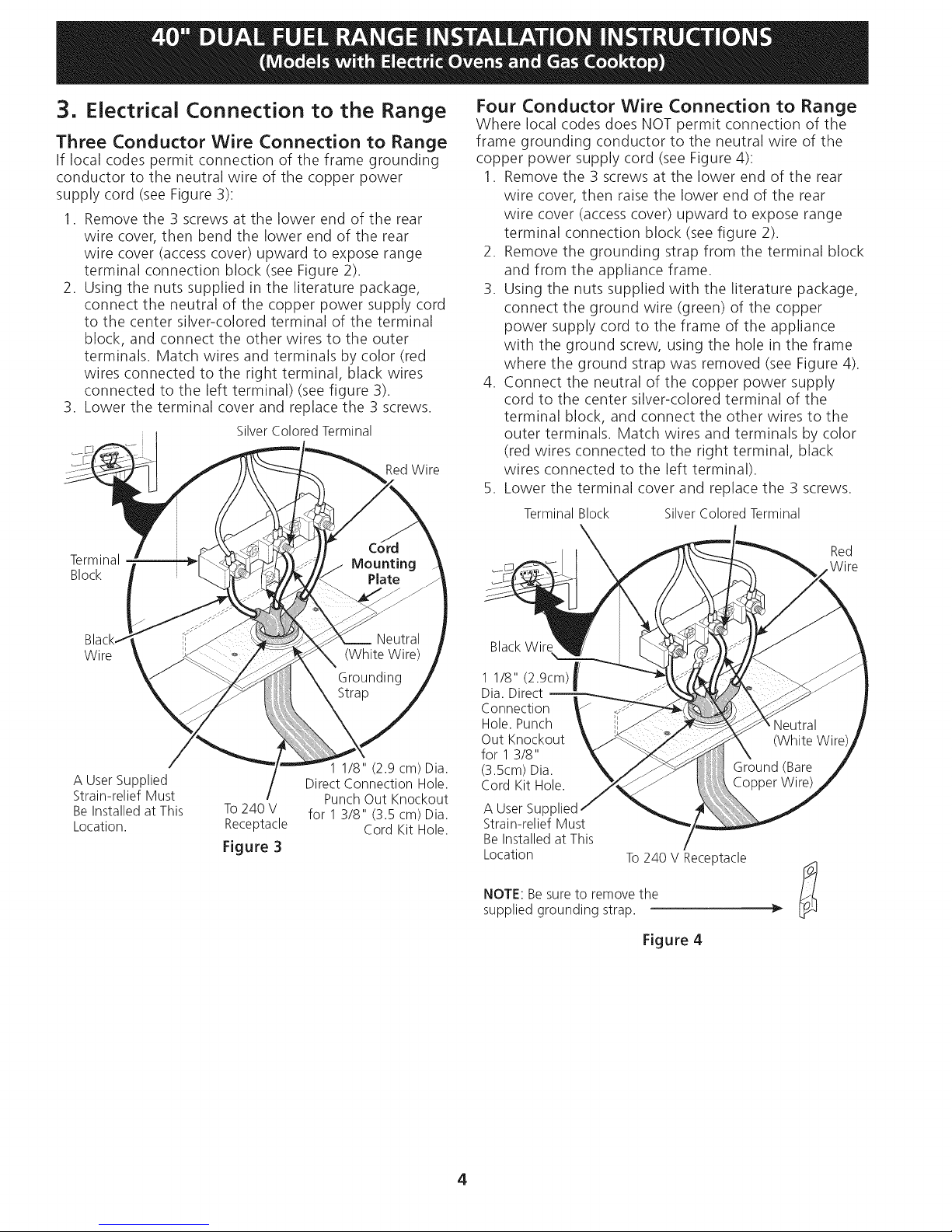
3, Electrical Connection to the Range
Three Conductor Wire Connection to Range
If local codes permit connection of the frame grounding
conductor to the neutral wire of the copper power
supply cord (see Figure 3):
1. Remove the 3 screws at the lower end of the rear
wire cover, then bend the lower end of the rear
wire cover (access cover) upward to expose range
terminal connection block (see Figure 2).
2. Using the nuts supplied in the literature package,
connect the neutral of the copper power supply cord
to the center silver-colored terminal of the terminal
block, and connect the other wires to the outer
terminals. Match wires and terminals by color (red
wires connected to the right terminal, black wires
connected to the left terminal) (see figure 3).
3. Lower the terminal cover and replace the 3 screws.
Silver Colored Terminal
RedWire
Four Conductor Wire Connection to Range
Where local codes does NOT permit connection of the
frame grounding conductor to the neutral wire of the
copper power supply cord (see Figure 4):
1. Remove the 3 screws at the lower end of the rear
wire cover, then raise the lower end of the rear
wire cover (access cover) upward to expose range
terminal connection block (see figure 2).
2. Remove the grounding strap from the terminal block
and from the appliance frame.
3. Using the nuts supplied with the literature package,
connect the ground wire (green) of the copper
power supply cord to the frame of the appliance
with the ground screw, using the hole in the frame
where the ground strap was removed (see Figure 4).
4. Connect the neutral of the copper power supply
cord to the center silver-colored terminal of the
terminal block, and connect the other wires to the
outer terminals. Match wires and terminals by color
(red wires connected to the right terminal, black
wires connected to the left terminal).
5. Lower the terminal cover and replace the 3 screws.
Terminal Block Silver Colored Terminal
Terminal
Block
Wire
A User Supplied
Strain-relief Must
Be Installed at This
Location.
To240 V
Receptacle
Figure 3
1 1/8" (2.9 cm) Dia.
Direct Connection Hole.
Punch Out Knockout
for 1 3/8" (3.5 cm) Dia.
Cord Kit Hole.
BlackWire
1 1/8" (2.9cm)_s
Dia. Direct
m
Connection
Hole.Punch
Out Knockout
for 1 3/8"
(3.5cm)Dia.
Cord Kit Hole.
A User Supl
Strain-relief Must
Be Installed at This
Location
NOTE: Be sure to remove the
supplied grounding strap.
To 240 V Receptacle
Red
Wire
Figure 4
4
Page 5
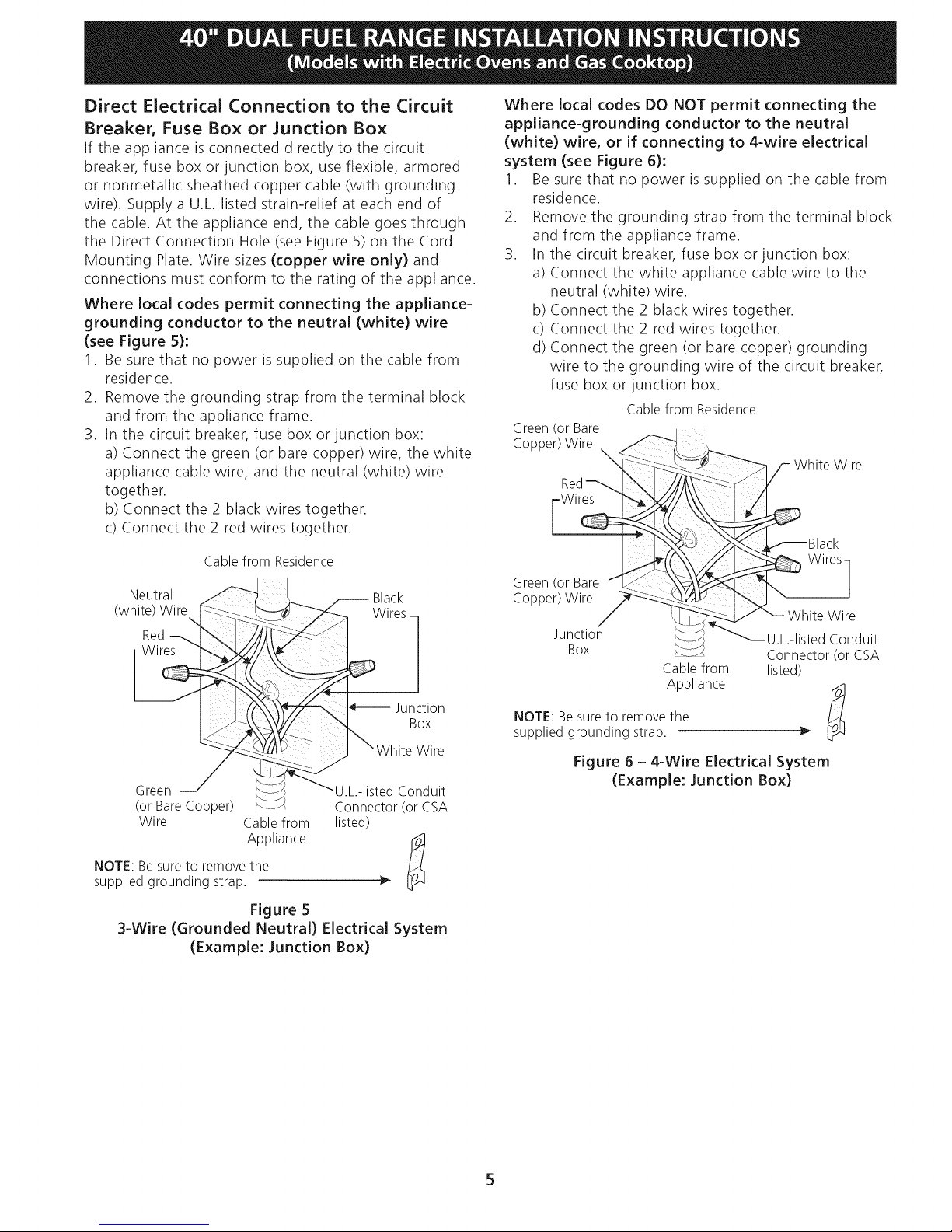
Direct Electrical Connection to the Circuit
Breaker, Fuse Box or Junction Box
If the appliance is connected directly to the circuit
breaker, fuse box or junction box, use flexible, armored
or nonmetallic sheathed copper cable (with grounding
wire). Supply a U.L. listed strain-relief at each end of
the cable. At the appliance end, the cable goes through
the Direct Connection Hole (see Figure 5) on the Cord
Mounting Plate. Wire sizes (copper wire only) and
connections must conform to the rating of the appliance.
Where local codes permit connecting the appliance-
grounding conductor to the neutral (white) wire
(see Figure 5):
1. Be sure that no power is supplied on the cable from
residence.
2. Remove the grounding strap from the terminal block
and from the appliance frame.
3. In the circuit breaker, fuse box or junction box:
a) Connect the green (or bare copper) wire, the white
appliance cable wire, and the neutral (white) wire
together.
b) Connect the 2 black wires together.
c) Connect the 2 red wires together.
Where local codes DO NOT permit connecting the
appliance-grounding conductor to the neutral
(white) wire, or if connecting to 4-wire electrical
system (see Figure 6):
1. Be sure that no power is supplied on the cable from
residence.
2. Remove the grounding strap from the terminal block
and from the appliance frame.
3. In the circuit breaker, fuse box or junction box:
a) Connect the white appliance cable wire to the
neutral (white) wire.
b) Connect the 2 black wires together.
c) Connect the 2 red wires together.
d) Connect the green (or bare copper) grounding
wire to the grounding wire of the circuit breaker,
fuse box or junction box.
Cablefrom Residence
Green(or Bare
Copper)Wire \ _
/- White Wire
Red '!!
I
Wires ' _
_glack
Cable from Residence
Neutral "-'_--'_ _ Black
(white) Wire [_ :::._:-..,..,_-_'_ --_ Wires
, Wile_,_ \,,_I _ZIRed ::*:-1::::_;i_:--/
_ _ _" whiteB_ire
Green J _:'_-__UL listedConduit
(or BareCopper) ; ::- Connector(or CSA
Wire Cablefrom listed)
NOTE:Besureto removethe
suppliedgrounding strap.
Appliance
Figure 5
3-Wire (Grounded Neutral) Electrical System
(Example: Junction Box)
Grepepne(r_i_ i
Junction _:7-'S
Box
Cablefrom
Appliance
NOTE: Be sure to remove the
supplied grounding strap.
Figure 6 - 4-Wire Electrical System
(Example: Junction Box)
Wires]
White WirJe
_U L-listed Conduit
Connector(or CSA
listed)
Page 6
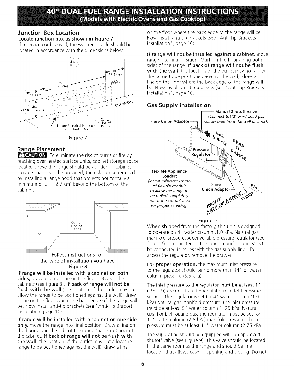
Junction Box Location
Locate junction box as shown in Figure 7.
If a service cord is used, the wall receptacle should be
located in accordance with the dimensions below.
Center
Line of
Range
ALL
"--. Center
Locate Electrical Hook-up
Inside Shaded Area
" Line of
Range
Figure 7
ement
To eliminate the risk of burns or fire by
reaching over heated surface units, cabinet storage space
located above the range should be avoided. If cabinet
storage space is to be provided, the risk can be reduced
by installing a range hood that projects horizontally a
minimum of 5" (12.7 cm) beyond the bottom of the
cabinet.
on the floor where the back edge of the range will be.
Now install anti-tip brackets (see "Anti-Tip Brackets
Installation" page 10).
If range will not be installed against a cabinet, move
range into final position. Mark on the floor along both
sides of the range. If back of range will not be flush
with the wall (the location of the outlet may not allow
the range to be positioned against the wall), draw a
line on the floor where the back edge of the range will
be. Now install anti-tip brackets (see "Anti-Tip Brackets
Installation", page 10).
Gas Supply Installation
l Manual Shutoff Valve
I (Connect to 1/2" or 3/4"solid gas
Flare Union Adaptor-----] I supply pipe from the wall or floor).
F leXlbcl:nA_p_a nee ___
(Install sufficient length
offlexibleconduit ... . \ \1%,
to allow the range to Union Adaptor _' _. k,_ "_ LL
be pulled completely . . _J_/__ < _
out of the cut-out area .,g_1,1_11_ _/_/ _<_
©
Center
Line of
Range
I
Follow instructions for
the type of installation you have
Figure 8
If range will be installed with a cabinet on both
sides, draw a center line on the floor between the
cabinets (see figure 8). If back of range will not be
flush with the wall (the location of the outlet may not
allow the range to be positioned against the wall), draw
a line on the floor where the back edge of the range will
be. Now install anti-tip brackets (see "Anti-Tip Bracket
Installation, page 10).
If range will be installed with a cabinet on one side
only, move the range into final position. Draw a line on
the floor along the side of the range that is not against
the cabinet. If back of range will not be flush with
the wall (the location of the outlet may not allow the
range to be positioned against the wall), draw a line
Figure 9
When shipped from the factory, this unit is designed
to operate on 4" water column (1.0 kPa) Natural gas
manifold pressure. A convertible pressure regulator (see
figure 2) is connected to the range manifold and MUST
be connected in series with the gas supply line. To
access the regulator, remove the drawer.
For proper operation, the maximum inlet pressure
to the regulator should be no more than 14" of water
column pressure (3.5 kPa).
The inlet pressure to the regulator must be at least 1"
(.25 kPa) greater than the regulator manifold pressure
setting. The regulator is set for 4" water column (1.0
kPa) Natural gas manifold pressure; the inlet pressure
must be at least 5" water column (1.25 kPa) Natural
gas. For LP/Propane gas, the regulator must be set for
10" water column (2.5 kPa) manifold pressure; the inlet
pressure must be at least 11 " water column (2.75 kPa).
The supply line should be equipped with an approved
shutoff valve (see Figure 9). This valve should be located
in the same room as the range and should be in a
location that allows ease of opening and closing. Do not
Page 7
blockaccesstotheshutoffvalve.Thevalveisforturning
onorshuttingoffgastotheappliance.Opentheshutoff
valveinthegassupplyline.Waitafewminutesforgas
tomovethroughthegasline.
Thegassupplybetweentheshutoffvalveandthe
regulatormaybeconnectedbyrigidpipingor byC.S.A.
approvedflexiblemetallicunionconnectedpipingwhere
localcodespermituse.
Thegassupplypipingcanbethroughthesidewall
oftherightcabinet.Therightsidecabinetisanideal
locationforthemainshutoffvalve.
Donotmaketheconnectiontootight.
Theregulatorisdiecast.Overtighteningmaycrackthe
regulatorresultinginagasleakandpossiblefireor
explosion.
Assembletheflexibleconduitfromthegassupplypipe
tothepressureregulatorinthisorder:
1-manualshutoffvalve,2-flareunionadapter,
3-flexibleconduit,4-flareunionadapter,
5-pressureregulator.
Thegassupplylinetotheshutoffvalveshouldbe
1/2"or3/4"solidpipe.
Theusermustknowthelocationofthemainshutoff
valveandhaveeasyaccesstoit.
Checkalignmentof valvesafterconnectingthe
cooktopto thegassupplytobesurethemanifoldpipe
hasnotbeenmoved.
Disconnectthe rangeandits individualshutoff
valvefromthegassupplypipingsystemduringany
pressuretestingofthesystemattestpressuresgreater
than1/2psig(3.5kPaor 14"watercolumn).
LP/PropaneGasConversion
ThisappliancecanbeusedwithNaturalGasorPropane
Gas.Itisshippedfromthefactoryforusewithnaturalgas.
IfyouwishtoconvertyourrangeforusewithLP/Propane
gas,usethesuppliedfixedorifices;theyarecontainedin
aspecialbagalongwithinstructionsmarked"FORLP/
PROPANEGASCONVERSION",locatedonthe backof
therange,closeto theapplianceregulatorvalve.
Theconversionmustbeperformedbyaqualifiedinstaller,
LPsupplieror servicetechnicianin accordancewith the
installationinstructionsfurnishedwith thisrangeandall
codesandrequirementsofalllocalcodesandrequirements.
Failuretofollowinstructionscouldresultinseriousinjuryor
propertydamage.Thequalifiedagencyperformingthiswork
assumesresponsibilityfortheconversion.
Failuretomaketheappropriateconversion
canresultinpersonalinjuryandpropertydamage.
Whenusingflexiblegasconduit
sufficientslackto pulltherange
ontherange,allow
outsidethecutoutfor
cleaningorservicing.
NOTE:Donotallowtheflexible
betweenthewallandtherange.
conduittogetpinched
Tovisuallycheck,
removetherangedrawer.
Usepipe-jointcompoundmadeforusewithNaturaland
LP/Propanegastosealallgasconnections.Ifflexible
conduitisused,becertainthatit isnotkinked.
Leaktestingof the applianceshallbeconducted
accordingto the manufacturer'sinstructions,
Checkfor leaks.Afterconnectingtherangetothegas
supply,checkthesystemforleakswithamanometer.If
amanometerisnotavailable,turnonthegassupplyand
usealiquidleakdetectoratalljointsandconnectionsto
checkforleaks.
Donotuseaflameto checkforleaks
fromgasconnections.Checkingforleakswithaflame
mayresultinafireorexplosion.
Allopeningsinthewallorfloorwheretherangeisto be
installedmustbesealed.
Tightenallconnectionsif necessaryto preventgas
leakageinthecooktoporsupplyline.
Anyadditions,changesorconversions
requiredinorderforthisappliancetosatisfactorilymeet
theapplicationneedsmustbemadebyanauthorized
SearsServiceCenter,DistributororQualifiedAgency.
Moving the Appliance for Servicing and
Cleaning
Turn off the range line fuse or circuit breakers at the
main power source, and turn off the manual gas shut-off
valve. Make sure the range is cold. Remove the service
drawer and open the oven door. Lift the range at the
front and slide it out of the cut-out opening without
creating undue strain on the flexible gas conduit.
Isolate the range from the gas supply piping system
by closing its individual manual shutoff valve during any
pressure testing of the gas supply piping system at test
pressures equal to or less than 1/2 psig (3.5kPa or 14"
water column).
Make sure not to pinch the flexible gas conduit at the
back of the range when replacing the unit into the cut-
out opening. Replace the drawer, close the door and
switch on the electrical power and gas to the range.
If the pressure regulator is connected to rigid piping,
the regulator must be disconnected before moving the
appliance.
Reassemble in reverse order (see figure 9).
7
Page 8
Range Installation
NOTE:
1. The back of the range may be installed directly
against the rear wall of the structure.
2. To reduce possible scorching of vertical walls and
to minimize potential fire hazards under abnormal
surface unit use conditions such as high heat or
no pans and to conform to C.S.A. requirements,
a minimum of 21/2"(6.4 cm) spacing should be
provided on both sides of the cooktop.
3. If a wall is present on the left side of range, allow
a minimum of 2 3/4" (7 cm) to open the auxiliary
door.
Excessive Weight Hazard
• Use 2 or more people to move and install range.
• Failure to follow this instruction can result in
back or other injury.
Preparation
1. Put on safety glasses and gloves. Remove oven racks
and parts package from inside the oven. Remove
shipping materials, tape and protective film from the
range.
2. Take 4 cardboard corners from the carton. Stack
one on top of another. Repeat with other 2 corners.
Place corners lengthwise on the floor in back of the
range to support range.
3. Firmly grasp the range and gently lay it on its back
on the cardboard corners.
4. Remove the 4 shipping bolts from the skid. Discard
skid.
5. Lay a large piece of cardboard in front of the range.
Carefully stand the range upright on cardboard.
6. Adjust the leveling legs to a point where the range
base does not touch the floor.
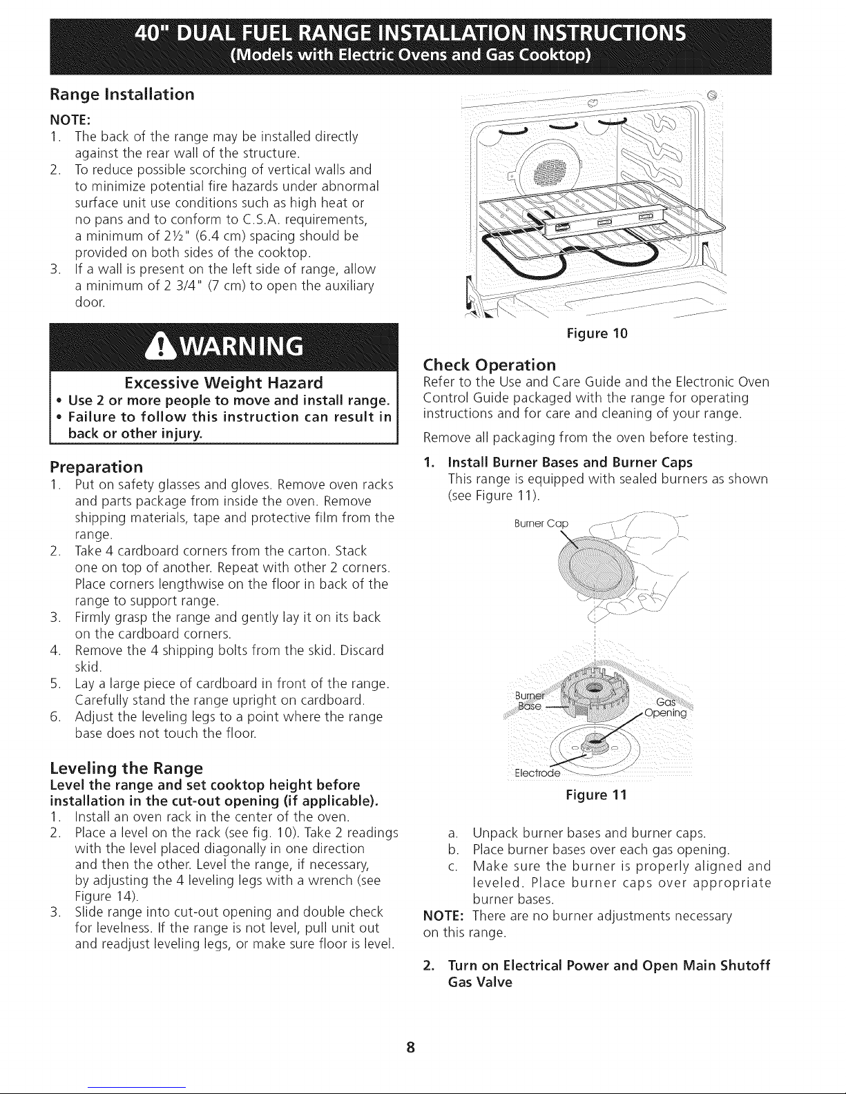
Figure 10
Check Operation
Refer to the Use and Care Guide and the Electronic Oven
Control Guide packaged with the range for operating
instructions and for care and cleaning of your range.
Remove all packaging from the oven before testing.
.
Install Burner Bases and Burner Caps
This range is equipped with sealed burners as shown
(see Figure 11).
Burner Cap _i_.---1,----i_..... " "
.............._. _. _ "_';_,-,/
\.;/
I
Burner
Base _ .
_t LTOS
_Jpen_ng
Leveling the Range
Level the range and set cooktop height before
installation in the cut=out opening (if applicable).
1. Install an oven rack in the center of the oven.
2. Place a level on the rack (see fig. 10). Take 2 readings
with the level placed diagonally in one direction
and then the other. Level the range, if necessary,
by adjusting the 4 leveling legs with a wrench (see
Figure 14).
3. Slide range into cut-out opening and double check
for levelness. If the range is not level, pull unit out
and readjust leveling legs, or make sure floor is level.
Electrode ......._ _ ......_/
Figure 11
a. Unpack burner bases and burner caps.
b. Place burner bases over each gas opening.
c. Make sure the burner is properly aligned and
leveled. Place burner caps over appropriate
burner bases.
NOTE: There are no burner adjustments necessary
on this range.
2. Turn on Electrical Power and Open Main Shutoff
Gas Valve
8
Page 9

3_
Check the Igniters
Operation of electric igniters should be checked after
range and supply line connectors have been carefully
checked for leaks and range has been connected to
electric power. To check for proper lighting:
a. Push in and turn a surface burner knob to the
LITEposition. You will hear the igniter sparking.
b. The surface burner should light when gas is
available to the top burner. Each burner should
light within four (4) seconds in normal operation
after air has been purged from supply lines.
Visually check that burner has lit.
c. Once the burner lights, the control knob should
be rotated out of the LITEposition.
There are separate ignition devices for each burner.
Try each knob separately until all burner valves have
been checked.
5. Operation of Oven Elements
The oven is equipped with an electronic oven control. Each
of the functions has been factory checked before shipping.
However, it is suggested that you verify the operation of
the electronic oven controls once more. Refer to the Use
and Care Guide for operation. Follow the instructions for
the Clock, Timer, Bake, Broil, Convection (some models)
and Clean (some models) functions.
When checking oven element operation,
do not touch the elements. They will be hot enough to
cause serious burns.
Bake-After setting the oven to 350°F (177°C) for
baking, the lower element in the oven should become
red.
Broil-When the oven is set to BROIL,the upper element
in the oven should become red.
4_
Adjust the "LOW" Setting of Surface Burner
Valves (see Figure 12)
a. Push in and turn each control to LITEuntil
burner ignites.
b. Quickly turn knob to LOWEST POSITION.
c. If burner goes out, readjust valve as follows:
Reset control to OFE Remove the surface burner
control knob, insert a thin-bladed screwdriver
into the hollow valve stem and engage the
slotted screw inside. Flame size can be increased
or decreased with the turn of the screw. Adjust
flame until you can quickly turn knob from LITE
to LOWEST POSITIONwithout extinguishing
the flame. Flame should be as small as possible
without going out.
Clean-When the oven is set for a self-cleaning cycle, the
upper element should become red during the preheat
portion of the cycle. After reaching the self-cleaning
temperature, the lower element will become red.
Convection-When the oven is set to CONV. BAKE/
ROAST at 350°F (177°C), both elements cycle on and
off alternately and the convection fan will turn. The
convection fan will stop turning when the oven door is
opened during convection baking or roasting.
When All Hookups are Complete
Make sure all controls are left in the OFFposition.
Before You Call for Service
Read the Avoid Service Checklist and operating
instructions in your Use and Care Guide. It may save you
time and expense. The list includes common occurrences
that are not the result of defective workmanship or
materials in this appliance.
Refer to the warranty and service information in your
Use and Care Guide for our phone number and address.
Please call or write if you have inquiries about your range
product and/or need to order parts.
Figure 12
9
Page 10

Important Safety Warning
To reduce the risk of tipping of the range, the range
must be secured to the floor by properly installed anti-tip
brackets and screws packed with the range. Those parts
are located in a plastic bag in the oven. Failure to install
the anti-tip brackets will allow the range to tip over if
excessive weight is placed on an open door or if a child
climbs upon it. Serious injury might result from spilled
hot liquids or from the range itself.
Follow the instructions below to install the anti-tip
brackets.
If range is ever moved to a different location, the anti-
tip brackets must also be moved and installed with the
range. To check for proper installation, see step 5.
Tools Required:
5/16" (8 mm) Nutdriver
Adjustable Wrench
Electric Drill
3/16" (4.8 mm) Diameter Drill Bit
3/16" (4.8 mm) Diameter Masonry Drill Bit (if installing in
concrete)
Anti-tip Bracket Installation
Brackets attach to the floor at the back of the range to
hold both rear leg levelers. When fastening to the floor,
be sure that screws do not penetrate electrical wiring or
plumbing. The screws provided will work in either wood
or concrete.
1. Unfold paper template and place it flat on the floor
with the back and side edges positioned exactly
where the back and sides of range will be located
when installed. (Use the diagram in figure 13 to
locate brackets if template is not available.)
2. Mark on the floor the location of the 4 mounting
holes (2 holes per bracket) shown on the template.
For easier installation, 3/1 6" (4.8 mm) diameter pilot
holes 1/2" (1.3 cm) deep can be drilled into the
floor.
3. Remove template and place brackets on floor with
turned up flanges to the outside (see figure 13).
Line up holes in brackets with marks on floor and
attach with 4 screws provided (2 screws per bracket).
Brackets must be secured to solid floor. If attaching
to concrete floor, first drill 3/1 6" (4.8 mm) dia. pilot
holes using a masonry drill bit.
4. Level range if necessary, by adjusting the 4 leveling
legs with a wrench. (See Figure 14 below.) A
minimum clearance of 1/8" (3.2 mm)is required
between the bottom of the range and the rear
leveling legs to allow room for the anti-tip brackets.
5. Slide range into place making sure rear legs are
trapped by ends of brackets. Range may need to be
shifted slightly to one side as it is being pushed back
to allow rear legs to align with brackets.
6. After installation, verify that the anti-tip bracket is
engaged. Open and remove drawer and check to
make sure the anti-tip bracket is engaged.
Anti-tip Bracket
Figure 13 Figure 14
Slide Back
Leveling Leg
Lower
10
Page 11

IMPORTANTE:GUARDEESTASINSTRUCCIONESPARA USO DEL INSPECTOR LOCAL DE ELECTRICIDAD.
LEA Y GUARDE ESTAS INSTRUCCIONES PARA REFERENCIA FUTURA.
OBSERVE C6DIGOS TODO GOBERNANTES Y ORDENANZAS.
Si la informad6n contenida en este manual no es seguida exactamente, puede
ocurrir un incendio o explosi6n causando dafios materiales, lesi6n personal o la muerte.
PARA SU SEGURIDAD: /_o_-\,
-- No almacene ni utilice gasolina u otros vapores y liquidos inflamables
en la proximidad de este o de cualquier otto artefacto.
-- QUE DEBE HACER SI PERCIBE OLOR A GAS:
• No trate de encender ningQn artefacto.
• No toque ningQn interruptor el_ctrico; no use ningQn tel_fono en su edifido.
• Llame a su proveedor de gas desde el tel_fono de un vedno.
Siga las instrucdones del proveedor de gas.
• Si no Iogra comunicarse con su proveedor de gas, Ilame al departamento de bomberos.
-- La instalad6n y el servicio de mantenimiento deben ser efectuados pot un instalador calificado,
la agenda de servido o el proveedor de gas.
36 3/8"
(92.4 cm) _-......... B
ill ii
23A"Min.
(7 cmMin.)
Sihayuno
pared,lado
izqu!
Vea
Nota
13" Max.
(45.7 cm Min.) (33 cm Max.)
O
uno pared:
2V2" Min.
(6.4 cm M[n.)
lado derecho
Tomacorriente d, (61 cm M[n.)
puesto a tierra 24V2" Max.
(62.2 cm Max.)
No pellizque el cordOn electrico entre la estufa y la pared.
No selle la estufa a los armarios de lado.
**NOTA: Un espacio mmimo de 24" (61 cm) entre la
superficie de la estufa y el fondo del armario cuando el
fondo del armario de madera o metal est,1 protegido pot
no menos de 1/4" (0.64 cm) de madera resistente al fuego
48 1/8" 40 1/8"
(122.2cm) (101.9cm)
26Y4" (66.7 cm) 44 5/8" (113.3 cm)
con la manilla 28Y2" (72.4)
24" M[n.
D
cubierta por una I_imina met_ilica de MSG, nOmero 28,
0.015" (0.4 ram) de acero inoxidable, 0.024" (0.6 mm) de
aluminio, 6 0.02" (0.5 mm) de cobre.
Un espacio m[nimo de 30" (76.2 cm) cuando el armario no
est,1protegido.
40 1/4" (102.2 cm) 36" (91.4 cm)standard
35 7/8" (91.1cm) min.
Imprimido en los Estados Unidos
P/N318201763 (0907) Rev.A
English- pages 1-10; Espa_ol- p_iginas 11-20
Notes- pages 21-23; Wiring Diagram - page 24
Page 12

Notas importantes para el Instalador
1.Lea todas las instrucciones contenidas en este manual antes
de instalar la estufa.
2. Saque todo el material usado en el embalaje del
compartimiento del homo antes de conectar el suministro
electrico a la estufa.
3.Dos soportes antivuelco DEBEN quitarse en el homo y
DEBEN set instalados. Para detalles, vea instrucciones en
la p_igina 20.
4. Observe todos los codigos y reglamentos pertinentes.
5. Deje estas instrucciones con el comprador.
Nota Importante para el Consurnidor
Conserve estas instrucciones y el Manual del Usuario para
referencia futura.
IMPORTANTES INSTRUCCIONES
DE SEGURIDAD
Instalacion de esta estufa debe cumplir con todos los codigos
locales, o en ausencia de codigos locales con el Codigo
Nacional de Gas Combustible ANSI Z223.1--01tima edicion.
El diseho de esta estufa ha sido certificado pot la
Asociacion de Gas Americana. En este como en cualquier
otto artefacto que use gas y genere calor, hay ciertas
precauciones de seguridad que usted debe seguir. Estas
set,in encontradas en el Manual del Usuario, lealo
cuidadosamente.
Todaslasestufas
pueden volcarse.
Estopodria
resultaren lesiones
personales.
Instaleel
dispositivo
antivuelco que
sehaempacado
junto con esta
estufa.
• Asegurese de que la estufa sea instalada y conectada
a tierra en forma apropiada pot un instalador
calificado o pot un tecnico.
• Esta estufa debe set electricamente puesta a tierra
de acuerdo con los cOdigos locales, o en su ausenda,
con el C6digo Electrico National ANSI/NFPA No. 70,
ultima ediciOn.
• La instalaciOn de aparatos disehados para instalaciOn
en casas prefabricadas (moviles) debe conformar con el
Manufactured Home Construction and Safety Standard,
t[tulo 24CFR, parte 3280 [Anteriormente el Federal Standard
for Mobil Home Construction and Safety, t[tulo 24, HUD
(parte 280)] o cuando tal est_indar no se aplica, el Standard
for Manufactured Home Installation 1982 (Manufactured
Home sites, Communities and Setups), ANSI Z225.1/NFPA
501A-ediciOn m_is reciente, o con los cOdigos locales.
Para reducir el riesgo de que
se vuelque la estufa, hay que
asegurarla adecuadamente
coloc_indole Los soportes
antivuelcoqueseproporcionan.
Paracomprobar si estos est_in
instalados y apretados en su
lugarcomosedebe,aseelborde
trasero superior de la estufa y
cuidadosamenteinclinela hacia
adelante para asegurarque la
estufaseancle.
• Asegurese de que el material que recubre las
paredes alrededor de la estufa, pueda resistir el
calor generado pot la estufa.
• Antes de instalar la estufa en un _rea cuyo piso
este recubierto con lin61eo u otto tipo de piso
sintetico, asegurese de que estos puedan resistir
una temperatura de pot Io menos 90°F sobre la
temperatura ambiental sin provocar encogimiento,
deformation o decoloradOn. No instale la estufa sobre
una alfombra al menos que coloque una plancha de
material aislante de pot Io menos 1_ pulgada, entre la
estufa y la alfombra.
• No obstruya el flujo del aire de combusti6n en la
ventilaci6n del homo ni tampoco alrededor de la
base o debajo del panel inferior delantero de la
estufa. Evite tocar las aberturas o _ireas cercanas de la
ventilacion, ya que pueden estar muy calientes durante el
funcionamiento del homo. Laestufa requiere aire fresco
para la combustion apropiada de los quemadores.
Nunca deje ni_os solos o
desatendidos en un _rea donde un artefacto est_
siendo usado. A medida que los nihos crecen, enseheles
el uso apropiado y de seguridad para todos los artefactos.
Nunca deje la puerta del homo abierta cuando la estufa
est,1 desatendida.
No se pare, apoye o siente en las
puertas o cajones de esta estufa pues puede resultar
en serias lesiones y puede tambien causar da_o a la
estufa.
• No almacene articulos que puedan interesar a los
ni_os en los gabinetes sobre la estufa. Los nihos
pueden quemarse seriamente tratando de trepar a la
estufa para alcanzar estos art[culos.
• Los gabinetes de almacenamiento sobre la estufa
deben set evitados, para eliminar la necesidad de
tenet que pasar sobre los elementos superiores de la
estufa para Ilegar a ellos.
• Ajuste el tama_o de la llama de los quemadores
superiores de tal manera que esta no sobrepase el
borde de los utensilios de cocinar. La llama excesiva es
peligrosa.
• No use el homo como espacio de almacenaje. Esto
create1una situacion potencialmente peligrosa.
• Nunca use la estufa para calentar el cuarto. El uso
prolongado de la estufa sin la adecuada ventilacion puede
resultar peligroso.
No almacene ni utilice gasolina u otros vapores y
liquidos inflamables en la proximidad de este o de
cualquier otto artefacto electrico. Puede provocar
incendio o explosion.
En caso de una interrupcion del servicio electrico, es posible
de encender los quemadores de superficie a mano. Para
encender un quemador de superficie, acerque un fosforo
encendido del cabezal del quemador, y gire delicadamente
el boton de control de superficie a LITE (encendido). Tenet
cuidado al encender los quemadores a mano.
• Ajuste todos los controles a la posici6n "OFF"
(apagada) despues de haber hecho una operaci6n
con tiempo programado.
12
Page 13

Ubicacion del Nurnero de Modelo y de Serie
La placa con el n0mero de serie est,1ubicada en el marco
delantero del homo detr_is de la puerta del homo grande.
Cuando haga pedidos de repuestos o solicite informacion
con respecto a su estufa, este siempre seguro de incluir el
n0mero de modelo y deserie y el n0mero o letra del Iote de
la placa de serie de su estufa (figura 1).
La placa de serie
est_ ubicada aqui. _ ...... .
........ Figura I
1, Estuche de cable del suministro electrico
El utilizados es responsable de la conexiOn del cable del
suministro el_ctrico al bloque de conexi6n situado detr_is
del panel de acceso.
El electrodom_stico se puede conectar a trav_s de un
cableado permanente "cableado duro"; cable de cobre
blindado armado o cable no-met_ilico flexible (cuando el
c6digo local Io permite) o pot medio de un kit de cable de
alimentaciOn.
NOTA: La cocina corrediza el6ctrica viene de fabrica con
un agujero de di_imetro 1 1/8" (2.9 cm) come se muestra
en la figura 4. Si un agujero mas largo est,1 necesario
retire la arandela de la pre-cortada.
F_ El riesgo de fuego o de choque
el6ctrico puede aparecer si usa el tamafio de cable
incorrecto, si las instrucdones de instalaci6n no son
seguidas o si retira la abrazadera de releva.
Para casassobre ruedas, nuevas instalaciones, en los
vehiculos de recreativos o en las lugares donde los c6digos
locales no permiten la conexi6n del conductor de tierra
al neutro, un ensamble de suministro el6ctrico de 4
conductores para estufas, calificado a 125/250 voltios
minimo, 30 Amperes minimo, debe de set utilizad.
IF.t_ No desajuste las tuercas que aseguran
[a conexi6n de la cocina a[ bloque terminal cuando
est6 instal,indola. El corte o la perdida de corriente
el6ctrica puede ocurrir.
2. Acceso a la terminal del bloque y
la correa de tierra
Cubierta de
acceso del
alarnbre trasero
Ubicad6n del
regulador de
presi6n
Figura 2
Este electrodom_stico fue fabricado
con el marco aterrizado a traves de una correa
de conexi6n entre el neutral de la fuente de
alimentaci6n y el marco. Si es utilizado en los E.E.
U.U., con un circuito nuevo de instalaci6n (1996
NEC), en casa sobre ruedas o vehiculo recreativo,
donde el codigo local no permite el atterizaje
a trav_s del cable neutro (blanco) o en Canada,
remueva la correa de aterrizaje del marco y corte
el otro extremo, cerca de la terminal de neutral.
Conecte el electrodom_stico de la forma usual
Peligro de choque el_ctrico
• Laconexion a tierra es requerida para este
electrodomestico.
Noconecte al suministro electrico hasta que el
electrodomestico este conectado atierra de rnanera
permanente.
• Desconecteel suministro electrico hacia la caja de
empalmes antes de hacer la conexion electrica.
• Esteelectrodomestico debe set conectado aun sistema
de alambres permanentes, metalicos, conectados a tierra
o una puesta a tierra debe set conectada al terminal de
tierra o un emplomando al electrodomestico.
Elno seguir ninguna de estasinstruccionespodria causar
fuego, heridas personaleso choques electricos.
13
Page 14

3. Conexion electrica a la cocina
Conexi6n del cable a tres alambres ia cocina
Si los c6digos locales permiten la conexi6n del conductor a
tierra del armaz6n al alambre neutral del cable de bronce
del suministro el@ctrico(vea figura 3).
1. Retire los 3 tornillos de la parte baja de la cubierta del
cable trasero (cubierta de acceso), luego levante la
cubierta hacia arriba para tener acceso al bloque de
conexi6n del borne terminal (vea figura 2).
2. Utilizar los tuercas suministraron en el paquete de la
literatura para conectar la parte neutral del cable de
bronce de suministro el_ctrico al terminal plateado que
se encuentra al centro del bloque terminal y, conectar
los otros alambres a los terminales externos. Aparee
los alambres y los terminales segOn el color (alambres
rojos conectados al terminal derecho, alambres negros
conectados al terminal izquierdo) (vea figura 3).
3. Baje la cubierta del terminal y vuelva al colocar los 3
tornillos.
Terminalplata
Alambre
rojo
Bloque
terminal
Conexi6n del cable de cuatro conductores a
ia cocina.
1. Retire los 3 tornillos de la parte baja de la cubierta
del cable trasero, luego levante la cubierta hacia
arriba para tener acceso (cubierta de acceso) al
bloque de conexi6n del borne terminal (vea figura 2).
2. Retire la correa de la base del bloque terminal y del
armaz6n del electrodom@stico. Retenga el tornillo de
la base.
3. Utilizar los tuercas suministraron en el paquete de la
literatura para conectar el alambre de tierra (verde)
del cable de bronce del suministro el@ctrico al
armaz6n del electrodom@stico con el tornillo de la
base, usando el hoyo del armaz6n por donde retir6
la correa de la base (vea figura 4).
4. Conecte el alambre neutral (blanco) del cable de
cobre del suministro el@ctrico al terminal plateado
del centro del bloque terminal y, conecte los otros
alambres a los terminales externos.
5. Baje la cubierta del terminal y vuelva al colocar los 3
tornillos.
Bloque terminal
Terminal plata
Alambre
'0
Alambre
Negro
Una arazadera de
releva provista debe
de estar instalada a
est,1ubicaci6n.
1 1/8" cm) Agujero
de la conexi6n directa.
Retira la arandela pre-
Hacia el 240 V cortada para 1 3/8" (3.5
Recept_iculo. cm) Dia. agujero.
Figura 3
Alambre
Ne(
1 1/8" (2.9 cm)
Dia. A,
de la conexi6n
directa. Retira
la arandela pre-
cortada para 1
318" (3.5 cm)
dia. agujero.
Una arazadera de
releva provista debe de
estar instalada a est,1
ubicaci6n.
NOTA: AsegOrese de quitar
la banda de puesta a tierra
provista.
Haciael 240V recept_iculo
/
Figura 4
14
Page 15

Conexion electrica directa ai cortacircuito, a
ia caja de fusibles o ia caja de empalmes
Si el aparato est_Sconectado directamente al cortacircuito,
a la caja de fusibles o a la caja de empalmes, use un cable
blindado flexible o no met_qlicorecubierto de cobre (con
alambre a tierra). Provee una abrazadera releva de anclaje
hom61ogo UL a cada extremidad del cable. A la extremidad
del electrodom_stico, el cable pase a trav_s del agujero
de la conexi6n directa (vet figura 5) en el cord6n de la
placa de montaje. El tamaho de los alambres (alambre de
cobre solamente) y las conexiones deben estar conforme
al r_gimen del electrodom_stico.
Donde los c6digos locales permitan conectar el
conductor de puesta a tierra del electrodom_stico al
neutral (blanco) (vea figura 5):
1. Desconecte el suministro el_ctrico.
2. Quite la banda de puesta a tierra de la caja de
empalmes y del marco de la estufa.
3. En el cortacircuito, la caja de fusibles o la caja de
empalmes:
a) Conecte el alambre verde (o cobre desnudo), el
alambre blanco del cable del electrodom_stico y el
alambre neutral (blanco)juntos.
b) Conecte los dos alambres negros juntos.
c) Conecte los dos alambres rojos juntos.
Cable de la fuente de
alimentaciOn
Alambre neutro _ Alambres
(blanco) negros
Alambres
rojos
Caja de
empalmes
Alambre blanco
Alambre
desnudos
overdes
Cable de la
estufa
Conductorde
uni6n listado-UL
(listado-CSA)
Donde los c6digos locales NO permitan conectar el
conductor de puesta a tierra del electrodom_stico al
neutral (blanco), o si est_ conectado con un sistema a
4 alambres (vea figura 6):
1. Desconecte el suministro el_ctrico.
2. Separe el alambre verde (o cobre desnudo) y el
alambre blanco del electrodom6stico.
3. En el cortacircuito, la caja de fusibles o la caja de
empalmes:
a. Conecte el alambre blanco del cable del
electrodom6stico al alambre neutral (blanco).
b. Conecte los 2 alambres negros juntos.
c. Conecte los 2 alambres rojos juntos.
d. Conecte el alambre verde (o de cobre desnudo) de
la puesta a tierra del alambre al alambre de puesta
a tierra del cortacircuito, de la caja de fusibles o de
la caja de empalmes.
Alambre
desnudo
o verde
Alambres
rojos
Cable de la fuente de
alimentaciOn
Alambre blanco
1
-- Alambres
Alambre
desnudo
o verde
Caja de
empalmes
Cablede la
estufa
NOTA: Asegurese de quitar
la banda de puesta a tierra provista.
Figura 6
Sistema El_ctrico a 4 Alambres
(Ejemplo: Caja de empalmes)
negros
Alambre blanco
Conductorde
uni6n listado-UL
(o listado-CSA)
NOTA: Aseg0rese de quitar
la banda de puesta a tierra
provista.
Figura 5
Sistema El_ctrico a 3 Alambres (Neutral puesta a tierra)
(Ejemplo: Caja de empalmes)
.S
15
Page 16

Situacion de caja de union
Localice la caja de ernpalmes como se ve en la Figura 7.
Si se usa un cord6n de servicio, el recept_iculo de pared
debe estar Iocalizado seg0n las medidas que se indican
abajo.
Construcci6n de los Armarios
Center
DELA ESTUFA
20" _ __. PARED
/ (50.8cm)f ! j_ _-- __:
10,,_14 -'_ <!<< _ L_<, T- i
(17.8 cm Max.) I I _._ <" \-._ _
_,,jff \ L-:_ _ Center
....................L UBIQUE LO ELECTRICO DE LA
incendios al tocar superficies sobrecalentadas, se debe evitar
colocar espacio para armarios de almacenamiento sobre
las estufas con elementos al descubierto. Si se instalan
armarios sobre la estufa, se pueden reducir tales riesgos
instalando una campana purificadora que se proyecta
horizontalmente un minimo de 5" (12.7 cm) m_is afuera de
la parte inferior de los armarios.
Si la estufa se va a Jnstalar con un arrnarJo a arnbos
lados, marque el centro de la abertura del armario en el piso.
DENTRO DEL AREA ESTUFA
SOMBREADA
Figura 7
Para eliminar el riesgo de quemaduras e
Center
Line of
Range
parte trasera de la estufa no estar_ a ras con la pared
(la ubicacion del tomacorriente puede que no permita que la
estufa se pegue a ras con la pared), marque el piso donde el
borde trasero de la estufa estate1. Ponga el patron en el piso y
alinee el lado del patron con la I[nea marcada en el piso. Ali-
nee la parte trasera del patron con la pared trasera o la I[nea
marcada para la parte de atr_is de la estufa.
SJla estufa no ser_ Jnstalada junta contra un armarJo,
mueva la estufa a su posicion final. Marque el piso pot los
dos lados de la estufa. Si la parte trasera de la estufa no
estar,_ a ras con la pared (la ubicacion del tomacorriente
puede que no permita que la estufa se pegue a ras con la
pared), marque en el piso donde el borde trasero de la estufa
estate1.Ponga el patron en el piso y alinee los lados del patron
con las I[neas marcadas en el piso. Alinee la parte trasera del
patron con la pared trasera o la I[nea marcada para la parte
trasera de la estufa (vea instalacion del Soportes Antivuelco
p_igina 20).
Instalaci6n de ia alimentaci6n de gas
V_lvula Manual Externa de Cierre
(Conecte a un conducto sOlido de
Adaptor de gas suministro de gas de 1/2" o 3/4").
Reguladol
presi6n
Conector Flexible
para Artefactos
(Instale un conducto
Io suficientemente
largo para poder sacar la
estufa totalmente fuera
de la _rea recortada
para un servicio satisfactorio.)
Adaptor de gas.
I
I
Siga las instrucciones para el tipo de
instalaci6n que usted tenga
Figura 8
Si la parte trasera de la estufa no estar_ a ras con la
pared (la ubicacion del tomacorriente puede que no permita
que la estufa se pegue a ras con la pared), marque el piso
donde estate1el borde trasero de la estufa. Ponga el patron
en el piso, alineando la linea del centro del patron con la
marca en el centro de la abertura del armario. Ponga el borde
trasero del patron a ras contra la pared trasera o la linea mar-
cada para la parte de atr_is de la estufa.
Si la estufa se va a instalar con un armarJo a s6lo un
lado, mueva la estufa a su posicion final. Marque el piso pot
el lado de la estufa que no estate1contra el armario. Si la
Figura 9
Esta unidad ha sido ajustada para operar con un m01tiple de
admision para gas natural de 4" (1.0 kPa). Un regulador de
presion convertible esta conectado a la wilvula distribuidora
y DEBE set conectado en serie con la tuber[a de suministro
de gas.
Para la operaci6n apropiada, la m_ixima presiOn de
entrada al regulador no debe exceder la presion de una
columna de agua de 14 pulgadas (3.5 kPa).
La presion de entrada al regulador debe set pot Io menos 1
pulgada m_is grande que la wilvula distribuidora (.25 kPa).
El regulador ha sido ajustado para gas natural a 4 pulgadas
de presion para la wilvula distribuidora (1.0 kPa). La presion
de entrada debe ser pot Io menos de 5 pulgadas (1.25
kPa). Para propano I[quido a 10 pulgadas de presion para la
wilvula distribuidora (2.5 kPa) la presion de entrada debe set
pot Io menos de 11 pulgadas (2.75 kPa).
16
Page 17

La tuberfa deberfa set equipada con una wilvula de cierre
aprobada (vea Figura 6). Esta wilvula debe ubicarse en la
misma habitacion que la estufa en un lugar que permita
una facilidad de abrir y cerrar. No bloque el acceso a
la wilvula de cierre. La wilvula es para abrir o cerrar el
suministro de gas al aparato.
Abra la wilvula de cierre en la Ifnea de suministro de gas.
Espere unos minutos a que el gas se mueva pot el tubo.
El suministro de gas entre la wilvula de cierre y el regulador
se puede conectar con tuberfa rfgida o con tuberfa flexible
union met_ilica conectada y aprobada pot la C.S.A. donde
los codigos locales permiten.
La tuberfa del suministro de gas puede pasar pot la pared
lateral del armario derecho. El armario lateral derecho es un
lugar ideal para la wilvula de cierre principal.
No haga que la conexion este demasiado
apretada. El regulador est,1 fundido a troquel. Apret_indolo
demasiado podrfa romper el regulador resultando en escape
de gas y posiblemente un incendio o explosion.
Monte el conector flexible desde el tubo de suministro
de gas hasta el regulador de presion seg0n este orden:
1- wilvula de cierre manual, 2- adaptar de gas, 3-conector
flexible, 4- adaptar de gas, 5- regulador de presion.
La tuberfa de suministro de gas debe set de 1/2" o 3/4" D.I.
El consumidor debe saber la posicion de la wilvula principal
de cierre y tenet acceso f_icil a ello.
Cuando se usa un conducto flexible en la estufa, permita
suficiente flojedad como para sacar la estufa fuera del
recortado para la limpieza y el servicio.
NOTA: No permita que el conducto se pellizque entre la
pared y la estufa. Para verlo, saque el cajon.
Use un compuesto para junturas de tuberfa hecho para
uso con gas natural y de LP/Propano para sellar todas las
conexiones del gas. Si se usan los conectores flexibles
aseg0rese de que no esten enroscados.
Para verificar si hay fugas en el electrodomestico se
debe de seguir [as instrucciones de[ fabricante.
Asegurese de que no haya escapes de gas. Despues
de conectar la estufa al suministro de gas, compruebe el
sistema con un manometro. Si no tiene un manometro,
abre el gas y use un detector de fugas Ifquido en todas las
junturas y conexiones para averiguar si hay escapes de gas.
No use llama para controlar que no
hayan perdidas de gas. La comprobacion de perdidas de gas
con una llama puede resultar en un incendio o explosion.
Se debe sellar todas las aberturas en la pared o el piso donde
la estufa se instala.
Apriete todas las conexiones si hace falta para prevenir
fugas de gas en la superficie de la estufa o en la linea de
suministro.
Asegurese del alineamiento de las v&lvulas despues
de conectar la superficie de la estufa con el suministro del
gas para cerciorarse de que el tubo de escape no se haya
movido.
Desconecte esta estufa y su v&[vu[a individual de
cierre del sistema del suministro de gas durante cualquier
prueba de presion de ese sistema a presiones mayores de
1/2 psig (3.5 kPa o 14" columna de agua).
ConversiOn para uso de Propano Liquido
Este aparato puede set usado con gas natural o propano
Ifquido. Ha sido ajustado en la f_ibrica para operar con gas
natural solamente.
Si desea convertir su estufa para uso con propano Ifquido,
use los orificios provistos ubicados en el bolso que contiene
la literatura titulada "FOR LP/PROPANE GAS CONVERSION",
[ocaHzado en [a parte posterior de[ homo, cerca de [a
v_[vu[a de[ regu[ador del horno, Siga las instrucciones
que vienen con los orificios.
La conversion debe set efectuado pot un tecnico de servicio
capacitado, de acuerdo con las instrucciones del fabricante
y con todos los codigos y requisitos de las autoridades
correspondientes. El no seguir las instrucciones podrfa dar
como resultado lesiones graves o dahos a la propiedad. El
organismo autorizado para Ilevar a cabo este trabajo asume
la responsabilidad de la conversion.
La falta de una conversion apropiada
puede resultar en lesiones graves y dahos a la propiedad.
La instalacion y el servicio de manteni-
miento deben set efectuados pot un instalador calificado, la
agencia de servicio o el proveedor de gas.
La mudanza de[ aparato para reparaciones o
[impieza
Apague la corriente electrica a la estufa a la fuente de poder
principal, y apague la wilvula de cierre manual de gas. Aseg0-
rese de que la estufa este fresca. Quite el cajon de servicio y
abre la puerta del homo. Levante la frente de la estufa y deslf-
cela fuera de la abertura sin crear tension desmedida sobre el
conducto flexible de gas.
Ais[a [a estufa de[ sisterna de[ surninistro de gas cerran-
do su wilvula manual de cierre individual durante cualquier
prueba de presion del suministro del gas a presiones iguales a
menos de 1/2 psgi (.5 kPa o 14" columna de agua).
Aseg0rese de no pellizque el conducto flexible de gas detr_is
de la estufa al reemplazar la unidad en la abertura. Reem-
place el cajon, cierre la puerta y enciende el gas y la corriente
electrica a la estufa.
El regulador debe desconectares antes de mover el aparato,
si el regulador de la estufa se conecta a una caherfa rigida.
Re ensamble en orden inverso (consulte Figura 9).
17
Page 18

InstalaciOn de ia estufa
NOTA:
1. La parte trasera de la estufa puede set directamente
instalada a ras con la pared trasera de la estructura.
2. Para reducir posibles marcas o rayas de las paredes
verticales y minimizar los riesgos de choques electricos en
caso de condiciones de uso anormales como alto calor o
no cazuelas, y para conformar a los requisitos de C.S.A.,
un espacio mfnimo de 2 Y2" (6.4 cm) debe de set provisto
en ambos lados de la plancha de cocinar.
3. Si una pared se encuentra en el lado izquierdo de la estu-
fa, dejar 2 3/4" (7 cm) mfn. par abrir la puerta auxiliar.
Peligro de Peso Excesivo
. Use 2 personas o mas para mover e instalar [a estufa.
• Si no cump[e con esta instrucciOn, puede resu[tar en
daffo a la espaida u otra lesi6n,
PreparatiOn
1. Pongase guantes y anteojos de seguridad. Quite las parri-
Ilas del homo y paquete de piezas de adentro del homo.
Quite materiales de empaque, cinta y pelfcula protectiva
de la estufa.
2. Tome las 4 esquinas de carton de la caja de empaque.
Col0quelas una encima de otra. Repita esta operacion
con las otras 2 esquinas. Coloque las esquinas Iongitudi-
nalmente en el piso detr_is de la estufa, para apoyarla.
3. Sujete firmemente la estufa y suavemente recuestela en
su respaldo, en las esquinas de carton.
4. Quite los 4 pernos de empaque de la corredera. Descarte
la corredera.
5. Ponga el carton delante de la estufa. Cuidadosamente
pare la estufa en el carton.
6. Ajuste la patas de nivelacion al punto en que la base de
la estufa no toque el piso.
Figura 10
ComprobaciOn de[ Funcionamiento
Consulte el Manual del Usuario incluido con la estufa para
instrucciones de operacion y instrucciones para el cuidado y
limpieza de su estufa.
Quite todo el embalaje de la unidad antes de comprobarla.
1. InstaladOn de las tapas de quemadores
Esta plancha de cocinar est.1equipada con quemadores
sellados como se muestra (Figura 11)
A. Desembale lastapas de los quemadores y las bases.
B. Coloque las basas de quemador sobre cada tubo de
abertura de gas.
C. Aseg0rese que el quemador est.1correctamente
alineado y nivelado. Coloque cada tapa del
quemador debajo de cada base del quemador.
Tapa del
quemador
/
/
NivelaciOn de [a estufa
Nive[e [a estufa y ajuste [a a[tura de [a estufa antes de
insta[ar[a en [a abertura,
1. Coloque una parrilla del homo en el centro del homo.
2. Ponga un nivel sobre la parrilla (vea figura 9). Tome dos
lecturas con el nivel puesto diagonalmente en una direc-
cion y despues en la otra. Nivele la estufa, si es necesario,
ajustando las 4 patas niveladoras con una Ilave de tuercas
(Figura 11).
3. Deslice la estufa en la abertura y verifique la nivelacion otra
vez. Si la estufa no es nivelada, tire la unidad hacia afuera
y reajuste las patas niveladoras, o verifique que el piso sea
nivelado.
Figura 11
NOTA: No es necesario realizar ajustes en los quemadores
de esta plancha de cocinar.
18
Page 19

2. Endende la corriente electrJca y abre la v&lvula
principal de cJerre.
3_
Comprobaci6n de los Encendedores
El funcionamiento de los encendedores electricos
debe set comprobado despues de que la estufa y los
conectores a la tuber[a de suministro de gas hayan
sido comprobados pot escapes y la estufa haya sido
conectada electricamente. Para comprobar que el
encendido sea correcto:
a. Empuje y gire una perilla del quemador superior
hasta la posicion LITE (encender). Se podr[a o[r el
encendedor haciendo chispas.
b. El quemador se deber_i encender en cuatro (4)
segundos para un funcionamiento normal, luego
de que el aire haya sido purgado de la tuber[a de
suministro de gas. Controle visualmente que el
quemador se hay encendido.
c. Luego que el quemador se haya encendido, la
perilla debe set girada fuera de la posicion LITE.
Cada quemador tiene su encendedor individual.
Controle las perillas separadamente hasta que todas las
wilvulas hayan sido controladas.
4_
Ajuste de la Posici6n LOW (BAJA) Para la V_ilvula
del Quernador Superior (FJgura 12)
a. Gire la perilla a la posici6n LITE (encender) hasta
que el quemador encienda.
b. Rapidamente gire la perilla a la POSICION MAS
BAJA.
c. Si el quemador se apaga, reajuste la wilvula de la
siguiente forma: Mueva el control a la posicion
OFF (apagada). Saque la perilla de control del
quemador superior, inserte un destornillador piano
pequeho en el hueco del wistago del a wilvula
hasta enganchar el tornillo interior. El tamaho de la
llama puede set aumentado o disminuido girando
el tornillo. Ajuste el tamaho de la llama hasta que
pueda pasar r_ipidamente de la posicion LITE hasta
la posicion MAS BAJA sin que se apague la llama.
La llama debe set Io m_is pequeha posible sin que
se apague.
5. Funcionamiento de los Elementos del Horno
El homo est,1 equipado con un control electronico. Cada
funcion ha sido probada en la f_ibrica antes del transporte.
Sin embargo, sugerimos que Ud. verifique el funcionamiento
de los controles del homo una vez m_is. Vease el Manual del
Usuario para la operacion. Siga las instrucciones par el Reloj,
Minutero, Cocer, Asar, Conveccion (algunos modelos) y las
funciones de limpieza (algunos modelos).
' " "" " Alverificarelfuncionamientode
elemento de homo, no toque los elementos. EIIos tendr_in el
calor bastante para causar las quemaduras serias.
Cocer/Bake-Despues de poner el homo a 350°F (177°C)
para cocer, el elemento inferior debe ponerse rojo
Asar/BroiI-Cuando est,1 puesto para BROIL, el elemento
superior se debe poner rojo.
Limpieza/Clean-Cuando el homo est,1 puesto para un
ciclo de auto-limpieza, el elemento superior se pondr_i rojo
durante el perfodo de precalentamiento del ciclo. Despues
de alcanzar la temperatura de auto-limpieza, el elemento
inferior se pondr_i rojo.
Convecd6n/Convection-Cuando el homo se pone a
CONV. BAKE/ROAST a 350°F (177°C), los dos elementos se
enciendan y se apagan alternando en un ciclo y el ventilador
se pone en marcha. El ventilador de conveccion se parar_i
cuando se abre la puerta del homo durante el cocido o el
asado por conveccion.
Despues de Terminar ia Instalaci6n
Aseg0rese de que todos los controles esten en la posicion OFF
(apagada).
Antes de Llamar al Servicio
Lea la secciOn Lista de control de averfas en su Manual del
Usuario. Esto le podr_i ahorrar tiempo y gastos. Esta lista
incluye ocurrencias comunes que no son el resultado de
defectos de materiales o fabricacion de este artefacto.
Lea la garant[a y la informacion sobre el servicio en su
Manual del Usuario para obtener el n0mero de telefono
gratuito y la direccion del servicio. Por favor Ilame o escriba
si tiene preguntas acerca de su estufa o necesita repuestos.
b
Fi r 12
19
Page 20

Importante Advertencia de Seguridad
Para reducir el riesgo de que la estufa se vuelque, es
necesario asegurarla al piso instalando los soportes
antivuelco y los tornillos suministrados con la estufa. Las
piezas se encuentran en un saco de plastic0 en el homo. Si
no se instalan los soportes antivuelco la estufa se puede
volcar si se coloca exceso de peso en una puerta abierta o si
un niflo se sube a ella. Se pueden ocasionar lesiones graves
causadas pot los Ifquidos calientes derramados o pot la
estufa misma.
Siga las instrucciones que m_is abajo se indican para instalar
los soportes antivuelco.
Si la estufa es movida a otto lugar, los soportes antivuelco
deben tambien set movidos e instalados en la estufa. Para
controlar la instalacion apropiada, vea el paso n0mero 5.
Herramientas Necesarias:
Llave de tuerca de 5/16" (8 mm) Llave inglesa
Taladro electrico
Broca de 3/16" (4.8 mm) de di_imetro
Broca para taladro de mamposterfa de 3/16" (4.8 mm) de
di_i. (si se est,1 instalando en concreto).
Instrucciones de Instalaci6n del Soporte
Antivuelco
Los soportes se fijan al suelo en la parte trasera de la estufa
para sujetar ambos niveladores de las patas traseras. Cuando
los este instalando al piso, aseg0rese de que los tornillos
no penetren el alambrado electrico o plomerfa. Los tornillos
provistos pueden utilizarse en madera o concreto.
1. Desdoble la plantilla de papel y coloquela plana en
el piso con los bordes laterales y el trasero colocados
exactamente donde la parte trasera y los lados de la
estufa set,in colocados cuando sea instalada. (Use el
diagrama figura 13 para ubicar los soportes si no se
dispone de la plantilla).
2. Marque en el piso la ubicacion de los 4 agujeros de montaje
como se muestra en la plantilla. Para facilitar la instalacion,
se pueden taladrar agujeros piloto de 3/16" (4.8 ram) de
di_i. y 1/2" (1.3cm) de profundidad en el piso.
3. Saque la plantilla y coloque los soportes en el piso con
la brida hacia arriba dirigida hacia el frente. Alinee los
agujeros en los soportes con las marcas en el piso y
sujete con los 4 tornillos provistos. Los soportes deben
estar asegurados al piso firme. Si se va a instalar en
piso de concreto, primero debe taladrar agujeros gufa
de 3/16" (4.8 mm) de di_imetro usando una broca para
taladro de mamposterfa.
4. Nivele la estufa si es necesario ajustando las cuatro
patas niveladoras con una Ilave (Vet la Figura 14 abajo).
Se requiere un espacio libre mfnimo de 1/8" (3.2 mm)
entre la parte inferior de la estufa y los niveladores de
las patas traseras para dejar espacio para los soportes
antivuelco.
5. Deslice la estufa a su lugar asegur_indose de que
las patas traseras esten sujetas pot los extremos de
los soportes. La estufa puede necesitar set movida
ligeramente a un lado cuando ester siendo empujada
hacia atr_is para permitir que las patas se alineen con los
soportes.
6. Despues de haber realizado la instalacion verifique que
la fijacion de montaje est,1 empotrada. Abra la gaveta,
retire la gaveta y verifique para asegurarse que est,1
empotrada.
Anti-tip Bracket
Figure 13 Figure 14
Slide Back
2O
Page 21

Notes/Notas
21
Page 22

Notes/Notas
22
Page 23

L2
R-7
w_s
W-5
BR-14
W-I4
W-5
w-s '_ 2
[
• 7 •
OVEN ClRCUIT//CIRCUITO DE HORNO//CIRCUIT FOUR
CONVECTION FAN/
VENTILAOOR BE CONVECDTON/
VENTI[ATEUR CONVECTION
LATCH MOTOR/
MOTOR CERROJO/
MOTEURVERROU
OVEN LAMP]
LUZDEHORNO/
LUMIERE FOUR
OVEN LAMP/
LUZ DE HORNOI
LUMIERE FOUR
COOLING FAN/VENTILADOR DE ENFRIAMIENTO/
VENTILATEUR DE REFROtDIBBEMENT I
) / / - =
BR-14 Z
BR-14
RIGH/ALTA/HAUTE
\y
SOME MODELS/ALGUNOS MODELOS/
',, CERTAINS MODELES
J
L1 ELECTRONIC OVEN CONTROL/
BK-7 CONTROL DE HORNO ELECTRONICO/
CONTROLE ELECTRONIQUE FOUR
JJJiiJilliJJilliJilliJJilliJJJJJJJilliJJilliJJilil
J3
[]
[]
==
BR 14 Z
BR-14==
1
R-5:
BK-5
[]
[]
[]
[]
[]
ES 5XX
CONV []
BR[]
Plt
[]
[]
[]
L2 OUT Z
== BK-2O
==
== BK-2O
=
== BK-14
==
; BK 20
== BK-14
==0-6
==
==
==BL_8
TEMPERATURE PROBE/
SONDA OR TEMPERATURA/
SONDE THERMIQUE
DOOR SWITCH/
1NTERRUPTOR DE PUERTA/
INTERRUPTEUR PORTE
_--. BK-20 .........
MOTOR SWITCH LATCH/
INTERRUPTOR MOTOR DE LOQUETA DE PUERTA
INTERRUPTEUR MOTEUR VERROU
_---...<> BK-14
NO C
CONVECTION ELEMENT/
ELEMENTO DE OONVECCION/
ELEMENT CONVECTION
BAKE ELEMENT/
ELEMENTODE RORNO/
ELEMENT CUISSON
BROIL ELEMENT/
ELEMENTO DE ASADO/
El EMENT GRIt t AGE
BL-7
THERMAL CIRCUIT BREAKER/ I
INTERRMPTOR DE CZROUITO
TERMICO/BZSJONCTEUR THERMZQUEI
L •
AUXILIAIRY OVEN // HORNO
L1
LEFi OVEN DOOR SWlFCH/
INTERRUPTOR DE PUERTA DE HORNO IZQUIERDO/
INTERRUPTEUR DE PORTE DE FOUR GAUCHE
BK_lO
LEFT OVEN THER_JSTAT SW./ LEFT OVEN BROIL ELEMENT/
TNTENRUPTOR DE TERMOGTATO EtEMENTO bE ASAO0 DE BORHO IZQU[ERDO/
DE HORNO IZOBIERBO/ ELEMENT DE GRIllAGE FOUR GAUCHE
INTENRUPTEUR THERMOSTAT
DE FOUR GAUCHE BL-5 BL 5 BL 5
BK 5 INDI AT R _E H RN ELEMBNTO BE NORNEO
_ F R A HE ELEMENT BE CUIBBON TERMOSTATO DE £EGUR.DAD/
CAUTION:DISCONNECT POWER BEFORE SERVICING UNIT.
ATENCION:CORTAR LA CORRIENTE ANTES DE REALIZAR EL MANTENIMIENTO DEL ELECTRODOMESTICO.
ATTENTION;COUPEZ L'ALIMENTATION AVANT B'EFFECTUER LA REPARATION,
A LEFT OVEN_,)_R/J-NOICATOR/ LEFT OVEN BAKE ELEMENT/ENT/
- C u O_ll u ORNO IZQUIERO0/ SAFETY THERMOSTAT/
OUG UC
p W'_ FOUR GAUCHE _/_ mHER.OBTAT BE SURETE 5
_?Y_5 5 Y 5 1 ^_ 2 R-5 ^__
B
LABEL ALL WIRES PRIOR TO DISCONNECTION WHEN SERVICING CONTROLS.
WIRINGS ERRORS CAN CAUSE IMPROPER AND DANGEROUS OPERATION.
VERIFY PROPER OPERATION AFTER SERVICING,
ETIQUETE TODOS LOB CABLES ANTES DE DESCONECTAR CUANDO NASA EL SERVICIO A LOS CONTROLES,
ERRORES AL VOLVER A ENSAMBLAR LOS CABLES PUEDE CAUSAR FALLAS U OPERACIOMES PELIGROSAS.
VERIFTQUE IA CORRPCTA OPFRACION DESPUPS DEl SERVICIO.
IDENTIFIEZ TOBS LEG FILS AVAMT DE LED DEBRANCHER OUAND L'APPAREIL EST MORB SERVICE.
LEG ERREURS DE CONNECTION DE FILS PEUVENT CAUSER UN #AL FONCTIONNEMENT ET UN DANGER
D'USAGE DE L'APPAREIL. VERIFIEZ LE DON FONCTIONNEMENT DE L'APPAREIL APRES LE SERVICE.
LATERAL // FOUR AUXILIAIRE
LEFT OVEN LAdP/
LUZ DE RORNO £ZGUIERDO/
LAMPE DE FOUR 6AUCNE
BR 10 W_l
LEFT OVEN THERMOSTAT/
TERMOSTATO DE HORNO IZQUIERBO/
THERMOSTAT DE FOUR GAUCHE
=
= =
IIIIIIIIIIIIIIIIIIIIIIIIIIIIIIIIIIIIIIIIIIIIIIIIF
N
L2 EN =
L2
CONNECTOR/
CONECTOR/
CONNECTEUR
A_
DOOR LA]CR 8WI1CH
INI_RRUPIOR CERROJO
BE FUERTA/INTERRUPTEUR
DE PORTE VERROU \ /
COLOR CODE/CODI60S DE COLOR
CODE DE COULEUR
GY, GREY/GRID/BRIG
G, GREEN/VERDE/VENT
i W* WHITE/BLANCO/BLANC
i R, RED/ROJO/ROUBE
i O, ORANGE/NARANJA/DRANGE
i Y, YELLOW/AMARILLO/JAUNE
i _R* BROWB/CAFE/BRUN
i BL, BLBE/AZUL/BLEU
i BK, BLACK/NEGRO/NO_R
CODE GAUGE TEMP.'C CSA UL
COBIGO MEDIBA
CODE CALIBRE
1 18 125 0L1251 3173
2 IB 125 CL1251 3173
3 14 125 0L1251 3173
4 12 125 CL1251 3173
5 18 150 EXL-150 3321
6 18 150 EXL-150 3321
7 14 150 EXL-150 3321
8 12 150 EXL 150 332t
9 10 150 EXL 150 3321
10 18 200 SEW 1 3122
11 16 200 SEW 1 3122
12 12 250 3252
13 16 250 3252
14 20 150 EXL-150 3321
15 B 150 EXI-150 332t
16 B 60
17 10 60
1018 200 SEW-1 3122
19 20 125 0L1251 3173
20 20 200 SEW-1 3122
21 22 125 3266
22 22 150 10109
23 18 200 3573
34 18 200 35t2
35 18 BOO 35t2
37 14 200 3512
41 20 200 35i2
318045341 REV:A
IPAGE • 1 /2
23
Page 24

24
 Loading...