


INSTALLATION AND SERVICE MUST BE PERFORMED BY A QUALIFIED INSTALLER.
IMPORTANT: SAVE FOR LOCAL ELECTRICAL INSPECTOR'S USE.
READ AND SAVE THESE INSTRUCTIONS FOR FUTURE REFERENCE.
If the information in this manual is not followed
exactly, a fire or explosion may result causing property
damage, persona njury or death.
FOR YOUR SAFETY:
-- Do not store or use gasoline or other flammable vapors
and liquids in the vicinity of this or any other appliance.
-- WHAT TO DO IF YOU SMELL GAS:
• Do not try to light any appliance.
• Do not touch any electrical switch; do not use any phone
in your building.
• Immediately call your gas supplier from a neighbor's
phone. Follow the gas supplier's instructions.
• If you cannot reach your gas supplier, call the fire
®
• ALL RANGES
CAN TIP
• INJURYTO PERSONS
COULD RESULT
• INSTALL ANTI-TIP
DEVICE PACKED WITH
RANGE
• SEE INSTALLATION
INSTRUCTIONS
department.
-- Installation and service must be performed by aqualified
installer, service agency or the gas supplier.
RANGE
OVERALL 253/4"
O,MENS,ONi
DoorOpen,, 29
Clearances and Dimensions
1, Location_hecklocationwhere
the ranoe will be installed. Check
for proper electrical and gas
supply, and the stability of the
floor.
2. Dimensionsthatare shown must
be used, Given dimensions
provide minimum clearance,
Contact surface must be solid
and level,
PIN 316259309(0108)
..... [ I _ FRONT
HI ii
Minimum to
Wall on Eit 0
Sideof Range
Above 36 ]e 1_---3 0" -_1_
Height, _ I I I i
* Note; 3" _ 30 ....
Clearance
with 11000 or 2" *_
greater BTU Burners.
L
Minimum
.....
Minimum to
. Lau.ie_s un Maximum Depth
18 Either Side for Cabinets /-_
of Range. Above Range Top.
_r _25'!_
SIDE
VIEW
o
36" _
I
r
4_ 30" _ O'ClearanceBelowCookingTopandatRearofRange.
Provide Proper Fuel Type
Before Proceeding: Your range is preset to operate on LP/Propane Gasonly.
1
c _ ..........
H ........ i
!!
Fran;ais - Pages 9-16
Espafiol - Paginas 17-24
Important Notes to the Installer
1. Readallinstructionscontainedin theseinstallation
instructionsbeforeinstallingrange.
2. Removeallpackingmaterialfromtheovencompartments
beforeconnectingthegasandelectricalsupply to the
range.
3. Observe allgoverning codes and ordinances.
4. Be sureto leave these instructionswith the consumer.
Important Note to the Consumer
1. Keep these instructions with your owner's guide for
futurereference.
IMPORTANT SAFETY
INSTRUCTIONS
Installation ofthisrange mustconformwithlocal codesor,in
the absence of local codes, with the National Fuel Gas Code
ANSI Z223.1--1atest edition when installed in the United
States.
This range has been design certifiedby CSA International.
As with any appliance using gas and generating heat, there
are certain safety precautions you should follow. You will find
them in the Use & Care Manual. read it carefully.
Besureyour rangeisinstalled andgrounded properly
by a qualified installer or service technician.
This range must be electrically grounded in
accordance with local codes or, in their absence,
with the National Electrical CodeANSI/NFPA No .70.--
latest edition when installed in the United States.
See GroundingInstructionson page 5.
Before installing the range in an area covered with
linoleum or any other synthetic floor covering, make
sure the floor covering can withstand heat at least
90°F above room temperature without shrinking,
warping or discoloring. Do not installthe range over
carpetingunless you placean insulatingpad or sheet of
1/4-inchthickplywoodbetweentherangeandcarpeting.
Make sure the wall coverings around the range can
withstand the heat generated by the range.
Do not obstruct the flow of combustion air at the
oven vent nor around the base or beneath the lower
front panel of the range. Avoid touching the vent
openings or nearby surfacesas they may become hot
whiletheoven is inoperation.Thisrange requiresfresh
air for properburnercombustion.
Never leave children alone or unattended
inthe area where an appliance is inuse. Aschildrengrow,
teach them the proper, safe use of all appliances. Never
leavethe oven dooropen when the range isunattended.
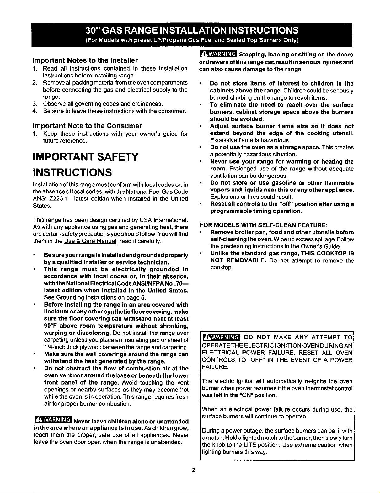
Stepping, leaning or sitting on the doors
or drawers of this range can result in serious injuries and
can also cause damage to the range.
Do not store items of interest to children in the
cabinets above the range. Children could be seriously
burned climbing on the range to reach items.
To eliminate the need to reach over the surface
burners, cabinet storage space above the burners
should be avoided.
Adjust surface burner flame size so it does not
extend beyond the edge of the cooking utensil.
Excessive flame is hazardous.
Do not use the oven as a storage space. This creates
a potentially hazardous situation.
Never use your range for warming or heating the
room. Prolonged use of the range without adequate
ventilation can be dangerous.
Do not store or use gasoline or other flammable
vapors and liquids near this or any other appliance.
Explosions or fires could result.
Reset all controls to the "off" position after using a
programmable timing operation.
FOR MODELS WITH SELF-CLEAN FEATURE:
• Remove broiler pan, food and other utensils before
self-cleaning the oven. Wipe upexcessspillage.Follow
the precleeninginstructionsin the Owner'sGuide.
Unlike the standard gas range, THIS COOKTOP IS
NOT REMOVABLE, Do not attempt to remove the
cooktop.
DO NOT MAKE ANY ATTEMPT TO
OPERATE THE ELECTRIC IGNITION OVEN DURING AN
ELECTRICAL POWER FAILURE. RESET ALL OVEN
CONTROLS TO "OFF" IN THE EVENT OF A POWER
FAILURE.
The electric ignitor will automatically re-ignite the oven
burner when power resumes ifthe oven thermostat control
was left in the "ON" position.
When an electrical power failure occurs during use, the
surface burners will continue to operate.
Duringa power outage, the surface burners can be litwith
a match. Hold alighted match to the burner, then slowly turn
the knob to the LITE position. Use extreme caution when
lighting burners this way.
Before Starting
Tools You Will Need
For leveling legs and Anti-Tip Bracket:
Adjustablewrench or channel lock pliers
5/16" Nutdriveror FlatHead Screw Driver
ElectricDrill&1/8"Diameter DrillBit(5/32"MasonryDrill
Bit if installingin concrete)
For gas supply connection:
Pipe wrench _
For burner flame adjustment:
Phillipshead _ and
blade-type screwdrivers
For gas conversion (LP/Propane or Natural):
Open endwrench - 1/2"
Additional Materials You Will Need
Gas line shut-offvalve I_
Pipe joint sealant that resists action of LP/Propane gas
A new flexiblemetal appliance conduit(1/2" NPTx 3/4"
or1/2"I.D.) mustbedesign certifiedbyCSAInternational.
Because solid pipe restricts moving the range we
recommend usinga new flexible conduit (4 to 5 foot
length) for each new installation and additional
reinstallations.
A°
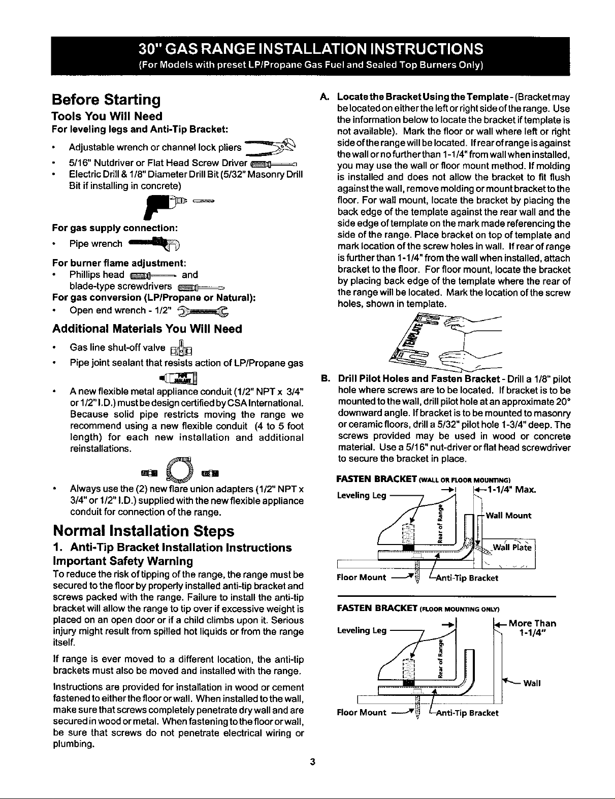
Locate the Bracket Using the Template- (Bracketmay
belocatedoneithertheleftorrightsideoftherange. Use
the informationbelowtolocatethe bracketiftemplate is
notavailable). Mark the flooror wall where leftor right
sideof therangewillbelocated. Ifrearof rangeisagainst
thewallornofurther than 1-1/4"from wallwheninstalled,
you may use thewall orfloor mountmethod. If molding
is installed and does not allow the bracket to fit flush
againstthe wall, removemoldingormountbrackettothe
floor. For wall mount, locate the bracketby placingthe
backedge ofthe template against the rearwalland the
sideedge oftemplate onthe markmadereferencingthe
side of the range. Place bracketontop of template and
marklocationof the screw holes inwall. Ifrear of range
isfurtherthan 1-1/4"from the wallwhen installed,attach
bracketto thefloor. Forfloor mount,locatethe bracket
by placing back edge of the templatewhere the rearof
therangewillbe located. Mark the locationofthescrew
holes, shown intemplate.
B,
Drill Pilot Holes and Fasten Bracket- Ddll a 1/8" pilot
hole where screws are to be located. If bracket is to be
mounted to the wall, drill pilot hole at an approximate 20 °
downward angle. If bracket is to be mounted to masonry
or ceramic floors, drill a 5/32" pilot hole 1-3/4" deep. The
screws provided may be used in wood or concrete
material. Use a 5/16" nut-driver or flat head screwdriver
to secure the bracket in place.
Always use the(2) newflare unionadapters (1/2" NPT x
3/4"or 1/2"I.D.) suppliedwiththenewflexibleappliance
conduitfor connectionofthe range.
Normal Installation Steps
1, Anti-Tip Bracket installation Instructions
Important Safety Warning
To reducethe riskof tippingofthe range,the range mustbe
securedto the floorby properlyinstalledanti-tipbracketand
screwspacked withthe range. Failure to installthe anti-tip
bracketwillallowthe rangeto tip over if excessive weight is
placedon an open dooror if a childclimbs upon it.Serious
injurymight result from spilled hotliquidsorfromthe range
itself.
If range is ever moved to a different location, the anti-tip
brackets must also be moved and installed with the range.
Instructionsare provided for installation in wood or cement
fastenedtoeitherthefloororwall. When installedtothe wall,
make surethatscrewscompletelypenetratedrywallandare
securedinwoodor metal. When fasteningto thefloororwall,
be sure that screws do not penetrate electrical wiring or
plumbing.
FASTENBRACKET(WALLORFLOORMOUN'nNG)
--_1 1<--'1"1/4"Max.
Leveling Leg _._ _
I wa''°°u°t
[ ...........! I i
L_._ _t / I1"- , _. i
Floor Mount -_'_'_ L-Anti-Tip Bracket
FASTEN BRACKET(FLOORMOUNTINGONLY)
--,I
Leveling Leg --
Floor Mount =Bracket

C. Level and Position Range - Level range by adjusting
the (4) leveling legs with a wrench. Note: A minimum
clearance of 1/8" is required between the bottomof the
rangeandthe leveling legto allow roomfor the bracket.
Usea spiritlevelto check youradjustments. Slide range
backintoposition.Visuallycheckthat rear levelingleg is
insertedintoand fullysecuredbytheAnti-TipBracketby
removinglowerpanelorstoragedrawer. Formodelswith
a warmer drawer or broilercompartment, graspthe top
rear edge of the range and carefully attempt to tilt it
forward.
(17ram)
%
Range Side _"
3. Seal the openings.
Sealanyopeningsinthewallbehindthe rangeandinthe floor
underthe range aftergas supplyline is installed.
2. Provide an adequate gas supply.
Thisunitis pre-settooperateon10"LP/Prepanagas manifold
pressure.Aconvertiblepressureregulatorisconnectedtothe
manifold and MUST be connected in series with the gas
supply line.
Care mustbetaken dudnginstallationofrangenotto obstruct
theflow ofcombustionand ventilationair.
For proper operation, the maximum inlet pressure to the
regulatorshouldbe nomorethan 14 inchesofwatercolumn
pressure.The inletpressureto the regulatormust beat least
1inchgreaterthan regulatormanifoldpressure.Examples; If
regulatorhas beensetfor LP/Propane gas 10 inch manifold
pressure, inletpressure mustbe atleast 11 inches.
Leaktesting ofthe applianceshallbeconducted according to
the instructions in step 4g.
The gas supplyline should be 1/2" or 3/4" I.D.
4. Connect the range to the gas supply.
To preventleaks, puta pipejointsealantonallmale (outside)
pipethreads,
Your regulator isin the locationshown below.
Do not allow regulator to turn on pipe when
tightening fittings.
aa_
Regulatel
Regulator
Gas
Service
Gas Shut-OffValve
shown in the

Manual Flare Flexible Flare Union Pressure
Shu_vOff Union AcPoP/ic_ncte Adaptor Regulator
(ShowninON Position).
Besureleverisinthe "On"position when
installationiscomplete
a) Install an externalmanual gas shut-off valve to gas supply
line inan easily-accessible location outside of the range.
Be sure you know how and where to shut-off the gas
supply to the range.
b) Install 1/2" flare union adapter to pressure regulator.
c) Attach appliance conduit to flare union on regulator.
d) Install flare union adapter to external manual shut-off
valve.
e) Attach appliance conduitto flare union on shut-offvalve.
f) Make sure service shut-offvalve on pressure regulator is
in "ON" position.
g) Check for leaks. Turn the gas supply on to the renge and
use a liquid leak detector at all joints and conduits to
check for leaks in the system.
Do not use a flame to check for gas leaks.
Checking Manifold Gas Pressure
Disconnectthe range and its individualshut-offvalve from
thegas supply piping system duringany pressuretestingof
that system at test pressures greater than 14" of water
columnpressure (approximately 1/2"psig).
The appliance must be isolated from the gas supply piping
system by closing its individual manual shut-off valve dudng
any pressure testing of the gas supply piping system at test
pressures equal to or less than 14"of water column pressure
(approximately 1/2" psig).
Ifit should be necessary to check the manifoldgas pressure,
connect manometer (water gauge) orother pressure device
to the top burner right rear orifice. Using a rubber hose with
inside diameter ofapproximately 1/4," hold tubing down tight
over orifice. Turn burner valve on.
For an accurate pressure check have at leasttwo (2) other
top burners burning. Be sure the gas supply (inlet) pressure
is at least one inch above specified range manifold pressure.
The gas supply pressure should never be over 14" water
column. When propedy adjusted for LP/Propane Gas the
manifold pressure is 10".
5. Read electrical connection details below and
connect electricity to range,
Before servicing, disconnect electrical
supply at circuit breaker, fuse or power cord.
Electric Reouirements: Anindividual,propedy grounded and
polarized branch circuit protected by a 15amp. circuit breaker
or time delay fuse. See serial plate for proper voltage.
ExtensionCord Precautions:
Becauseofpotential safety hazards under certainconditions,
we strongly recommend against the use of any extension
cord. However, ifyou still elect to use an extension cord, it is
absolutely necessary that it bea UL listed 3-wire grounding
type appliance extension cord and that the current carrying
rating of the cord in amperes be equivalent to orgreater than
the branch circuit rating. Such extension cords are obtainable
through your local service organization.
PLEASE READ CAREFULLYI Forpersonal
safety, thisproduct must be properly grounded.
Grounding Instructions
The power cord ofthis applianceis equippedwith a
3-prong(grounding)plugwhich mateswith a standard
3-pronggroundingwallreceptacletominimizethepossibility
ofelectricshockhazard from thisappliance. The customer
should have the wall receptacle and circuit checked by a
qualifiedelectricianto make sure the receptacleis properly
groundedand polarized.
Preferred Method ./I /f Do Not, Under
Grounding Cord with
Type 3-Prong
Wall Grounding
Receptacle Plug
/ I _J Any Circumstances, I
/._: I _ Cut, Remove, |
Power Supply
___ _s;hPeOng" j)
Where a standard two-prongwallreceptacleisencountered,
itisthepersonal responsibilityandobligationofthe customer
tohaveitreplaced witha propedygroundedthree-prongwall
receptacle.
DO NOT, UNDER ANY CIRCUMSTANCES, CUT OR
REMOVE THE THIRD (GROUND) PRONG FROM THE
POWER CORD.

Operation of Surface Burners
6. Installation of Burner Cap Assembly
Your range isequipped with any combinationofthe sealed
burners. Refer to the chart to find yoursurface burner and
surfaceburnercapconfiguration.Besureto placethecorrect
burnercap at onall four surfaceburners,
PossibleSurfaceBurnerandCap configurations:
Install the parts shown below at all four surface burner
locations:
1st- Install the surface burner pans (if equipped); 2nd -install
the surface burner heads; 3rd- install thesurface burnercaps
and 4th; install the burner grates.
Surface
Burner
Grate
7. Electric Ignition Surface Burners
Operation of electric igniters should bechecked after range
and supply line connectors have been carefully checked for
leaks and range has been connected to electric power.
a. To check for proper lighting, push in and turn a surface
burner knob counterclockwise to the LITE position.
You willhear the ignitersparking.
b,
The surface burner should light whengas is available to
the top burner. Purge air from supply lines by leaving
knob in the LITE position until burner ignites. Each
burner should light within four (4) seconds in normal
operation after air has been purged from supply lines.
c. Visually check that burner has lit. Once the burner lights,
the control knob should beturned out of the LITE position.
d. There are separateelectrodes(igniters) for each burner.
Try each knob separately until all burner valves have
been checked.
Note: Knob styles may vary from those pictured below.
Surface
(_Burner
_._d) Surface
Orifice
Hold_ Electrode _e models)
Cap
Burner
Head
Removable
Burner
Drip Pan
I OFF ..LITE..hi 6 5 4 3 2 Io ]

8. Adjust the "LOW" Setting of Surface Burner
Valve (Linear Flow Valves Only):
To
Surface
Burner
Test to verify if "LOW"settingshouldbe adjusted
a. Push in and turn control to LITE until burner ignites.
b. Push in and auickty turn knob to LOWEST POSITION.
c. If burner goes out, reset control to OFF.
d. Removethe surface burner control knob.
e. Insert a thin-bladed screwdriver into the hollow valve
stem and engage the slotted screw inside. Flame size
can be increased or decreased with theturn ofthe screw.
Turn counterclockwise to increase flame size. Turn
clockwise to decrease flame size.
BurnernameSize -_1 5/8' t_
After removing all packing materials and literature from the
oven:
a) Set oven to BAKE at 300°F. See Use& Care Manual for
operating instructions.
b) Within 60 seconds the oven burner should ignite. Check
for proper flame, and allow the burner to cycle once.
Reset controls to off.
c) If your model is equipped with a waist-high broiler, set
oven to BROIL. See Use & Care Manual for operating
instructions.
d) Within 60 seconds the broil burner should ignite. Check
for proper flame. Reset controls to off.
10. Air Shutter-Oven Burner
Waist-High Burner
(SelfClean Models)
i
_Air Shutter
Adjust flame until you can quickly turn knob from LITE to
LOWEST POSITION without extinguishing the flame. Flame
should be as small as possible without going out.
Note: Air mixture adjustment is not required on surface
burners.
Operation of Oven Burners and
Oven Adjustments
9, Electric Ignition Burners
Operationofelectricignitersshouldbe checked after range
and supplylineconnectorshave been carefullycheckedfor
leaks and range has been connectedto electricpower,
The oven burner is equippedwithan electriccontrolsystem
as well as an electric oven burner igniter. If your model is
equipped with a waist-highbroilburner, itwill alsohave an
electnc burner igniter, These control systems require no
adjustment.When the oven issettooperate, currentwillflow
to the igniter.It will"glow" similarto a lightbulb. When the
igniterhas reached a temperaturesufficientto ignitegas,the
electrically controlled oven valve will open and flame will
appear at theoven burner.There ise time lapse from 30 to
60 seconds after the thermostat is turned ON before the
flame appears at the oven burner. When the oven reaches
the dial setting,the glowing igniterwill go off. The burner
flame willgo "out" in20 to 30 secondsafterthe ignitergoes
"OFF." To maintain any given oven temperature,this cycle
willcontinueas longas thedial(ordisplay) isset to operate.
Lower Oven Bottom
Air Shutter
(Removable)
The approximate flame length of the oven burner is 1 inch
(distinct inner, blue flame).
To determine ifthe oven burner flameis proper, removethe
oven bottomand burner baffle and set the oven to bake at
3OO°F.
To remove the ovenbottom, remove ovenhold down screws
atrearofoven bottom.Pullupatrear,disengagefrontofoven
bottomfrom oven front frame, and pullthe oven bottomout
ofthe oven. Remove burnerbaffle so that the burnerflame
can be observed.
If the flame is yellow in color, increase air shutteropening
size. (See "2" in illustrationbelow.) If theflame is a distinct
blue, reduce the air shutter openingsize.
To adjust loosen lock screw (see "3" illustration below),
reposition air shutter, and tighten lock screw. Replace oven
bottom.

Oven
Tube
® ®
(_Air Shutter Orifice
11. Air Shutter-Broil Burner
The approximateflame length of the broilburner is 1 inch
(distinctinner, blue flame).
To determine if the broil burner flame is proper, set the oven
to broil.
Before You Call for Service
Readthe "Before YouCall" and operating instruction sections
in your Use & Care Manual. It may save you time and
expense. The list includes common occurrences that are not
the result of defective workmanship or materials in this
appliance.
Refer to the warranty in yourUse& Care Manual for our toll-
free service number and address. Please call or write if you
have inquiries about your range product and/or need to order
parts.
i
If the flame is yellow in color,increase air shutter opening
size. (See "2" in illustration above.) If the flame is adistinct
blue, reduce the air shutter opening size.
To adjust, loosen lock screw (see "3" in illustration above),
reposition air shutter, and tighten lock screw.
12,Make Sure Range is Level.
Level the range by placing a level horizontally on an oven
rack. Check diagonally from front to back, then level the
range by either adjusting the leveling legs orby placing shims
under the corners of the range as needed,
13.After installation is complete, make sure all
controls are left in the OFF position,
Model and Serial Number Location
For sealed burner ovens, the serial plate is locatedon the
right-handsurface ofthe oven front frame at the storageor
warmer drawer;or the lowerpanel area.
When ordering parts for ormakinginquiresabout your range,
always be sure to include the model and serial numbers and
a lot number or letter from the sedal plate on your range.
n n _
60 O©
Your serial plate also tells youthe rating of the burners, the
type offuel andthe pressure the range was adjusted for when
it left the factory.
Care, Cleaning and Maintenance
Refer tothe Use & Care Manual for cleaning instructions.
If removing the range is necessary for cleaning or
maintenance, shut off gas supply. Disconnect the gas and
electrical supply. Ifthe gasor electrical supply isinaccessible,
lift the unitslightly at thefront and pull out away from the wall.
Pull only as far as necessary to disconnect the gas and
electrical supply. Finish removing the unit for servicing and
Serial plate location
Open storage or warmer drawer
or remove lower panel
(on some models)
 Loading...