

Frigidaire FLEB8200DS0, GLGT1142CS1, FLGB8200DS1, FLGB8200DS0, FLEB43RGS3 Installation Instructions Manual
...
Installation
Instructions
Full Size Laundry Center
Gas & Electric
Before beginning installation, carefully read these instructions. This will simplify the installation
and ensure the laundry center is installed correctly and safely. Leave these instructions near the
laundry center after installation for future reference.
NOTE: The electrical service to the laundry center must conform with local codes and ordinances
and the latest edition of the National Electrical Code, ANSI/NFPA 70, or in Canada, the Canadian
Electrical Code, CSA C22.1
NOTE: The gas service to the laundry center must conform with local codes and ordinances and
the latest edition of the National Fuel Gas Code ANSI Z223.1/NFPA 54, or in Canada, the Canadian
Natural Gas and Propane Installation Code, CSA B149. 1.
NOTE: The laundry center is designed under ANSI Z21.5.1 or ANSI/UL 2158- CAN/CSA C22.2
(latest edition) for HOME USE only. This laundry center is not recommended for commercial
applications such as restaurants or beauty salons, etc.
For your safety the information in
this manual must be followed to minimize the risk
of fire or explosion or to prevent property damage,
personal injury or loss of life.
- Do not store or use gasoline or other flammable
vapors and liquid in the vicinity of this or any
other appliance.
- WHAT TO DO IF YOU SMELL GAS
e Do not try to light any appliance.
t Do not touch any electrical switch; do not use
any phone in your building.
e Clear the room, building or area of all
occupants.
e Immediately call your gas supplier from a
neighbor's phone. Follow the gas supplier's
instructions.
e If you cannot reach your gas supplier, call the
fire department.
Installation and service must be preformed by a
qualified installer, service agency or the gas
supplier.
Contents
SUBJECT PAGE
Pre-lnstallation Requirements
Electrical Requirements
Water Supply Requirements
Drain Requirements
Exhaust SystemRequirements
Gas Supply Requirements
Location
Mobile Home Installation
Rough-In Dimensions
Unpacking
Electrical Installation
Grounding Requirements
3 & 4-Wire Connections
Installation
Replacement Parts
2
2
2
2
3
4
4
4
5
5
6
6
7
7
8
Printed in U,S,A. P/N131661700 (O11O)
PRE-INSTALLATION REQUIREMENTS
Tools and Materials Required for Installation:
1. Phillips head screwdriver.
2. Channel-lock adjustable pliers.
3. Carpenter's level.
4. Flat or straight blade screwdriven
5. Duct tape.
6. Rigid or flexible metal 4 inch (10.16 cm) duct.
7. Vent hood.
8. Pipe thread sealer (Gas).
9. Ratchet with 3/8 inch (0.96 cm) socket.
ELECTRICAL REQUIREMENTS
ELECTRICLaundry Center
Circuit- Individual 30 amp branch circuit fused with 30 amp
minimum time delay fuses or circuit breakers.
POWER SUPPLY- 3-wire or 4-wire, 240 volt, single phase, 60
Hz,Alternating Current.
POWER SUPPLYCORD KIT-The laundry center MUST employ
a 3-condutor power supply cord NEMA 10-30 type SRDTrated
at 240 volt AC minimum, 30 amp, with 3 open end spade lug
connectors with upturned ends or closed loop connector OR a
4-condutor power supply cord NEMA 14-30 type SRDTor ST
(asrequired) rated at 240 volt AC minimum, 30 amp, with 4
open end spade lug connectors with upturned ends or closed
loop connectors and marked for usewith clothes dryers. If being
installed in a manufactured (mobile) home, the laundrycenter
MUST employ a 4-condutor power supply cord NEMA 14- 30
type SRDTor ST(as required) rated at 240 volt AC minimum,
30 amp, with 4 open end spade lug connectors with upturned
ends or closed loop connectors and marked for usewith clothes
dryers. See ELECTRICALCONNECTIONS. (Canada - 4-wire
power supply cord isinstalled on laundry center.)
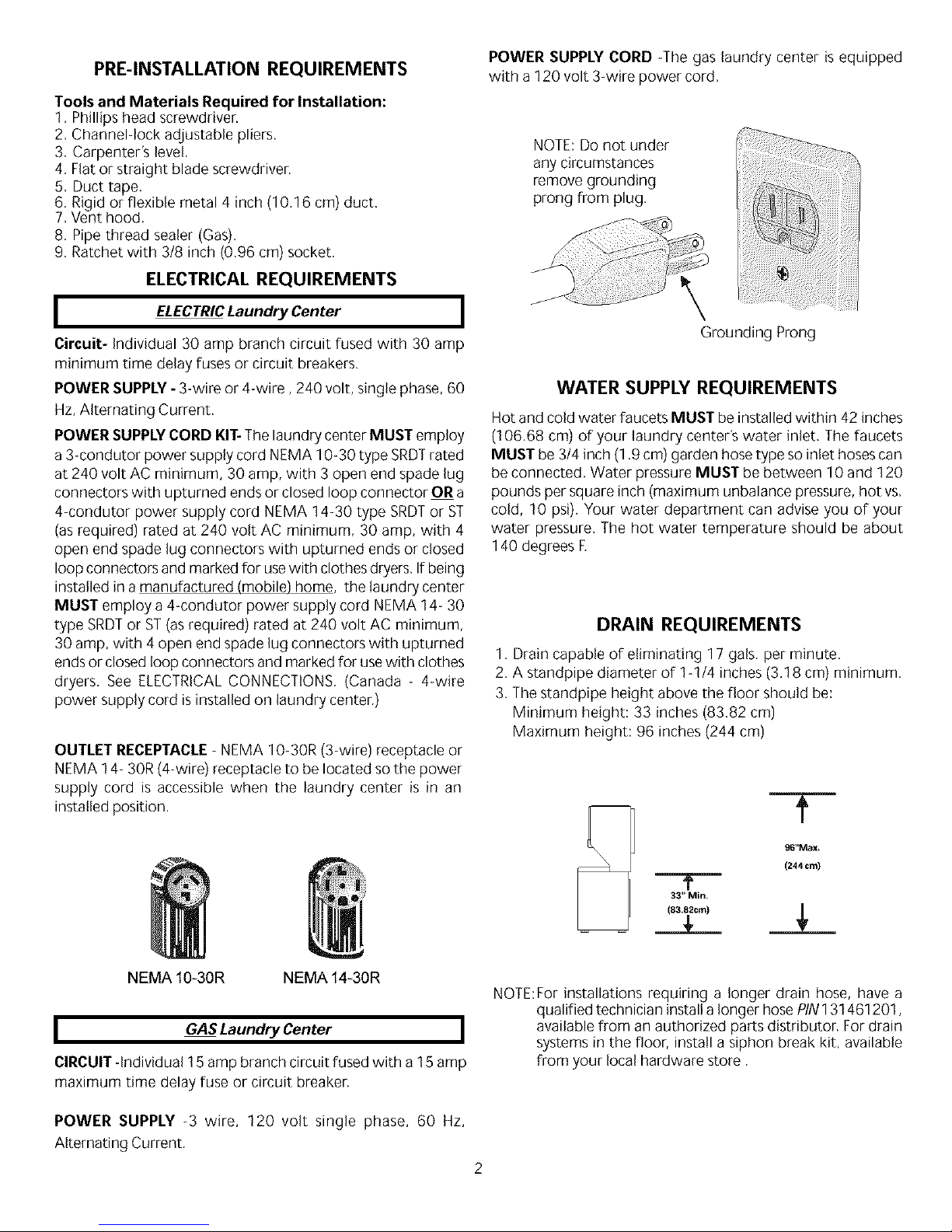
OUTLET RECEPTACLE- NEMA 10-30R (3-wire) receptacle or
NEMA 14- 30R (4-wire) receptacle to be located so the power
supply cord is accessible when the laundry center is in an
installed position.
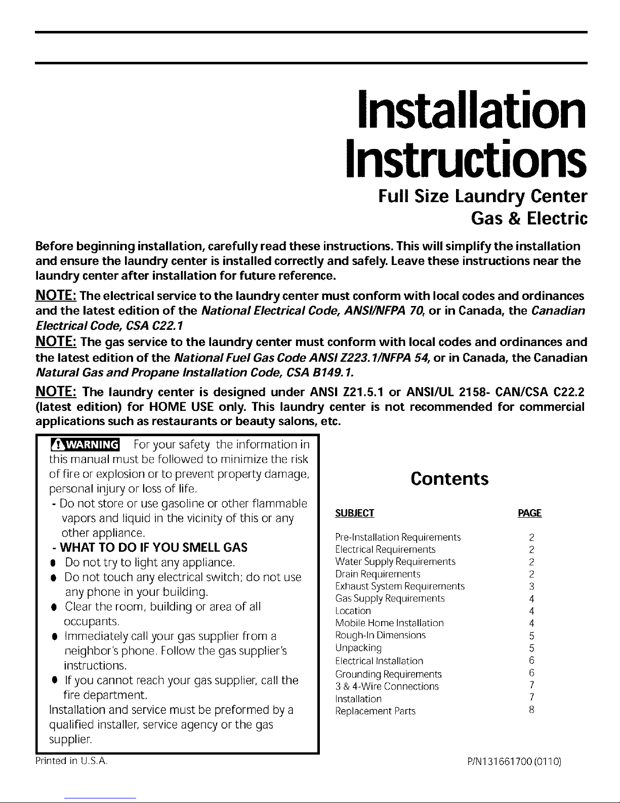
POWER SUPPLY CORD -The gas laundry center is equipped
with a 120 volt 3-wire power cord.
NOTE:Do not under
any circumstances
remove grounding
prong from plug.
\
Grounding Prong
WATER SUPPLY REQUIREMENTS
Hot and cold water faucets MUST be installed within 42 inches
(106.68 cm) of your laundry center's water inlet. The faucets
MUST be 3/4 inch (1.9 cm) garden hose type so inlet hoses can
be connected. Water pressure MUST be between 10 and 120
pounds per square inch (maximum unbalance pressure, hot vs.
cold, 10 psi). Your water department can advise you of your
water pressure. The hot water temperature should be about
140 degrees E
DRAIN REQUIREMENTS
1. Drain capable of eliminating 17 gals. per minute.
2. A standpipe diameter of 1-1/4 inches (3.18 cm) minimum.
3. The standpipe height above the floor should be:
Minimum height: 33 inches (83.82 cm)
Maximum height: 96 inches (244 cm)
T
96"Max.
(244 cm)
-"T"-
33" Min.
__L
NEMA 10-30R NEMA 14-30R
I GASLaundry Center I
CIRCUIT -individual15 amp branch circuit fused with a15 amp
maximum time delay fuse or circuit breaker.
NOTE:For installations requiring a longer drain hose, have a
qualified technician install a longer hose PIN131461201,
available from an authorized parts distributor. For drain
systems in the floor, install a siphon break kit, available
from your local hardware store.
POWER SUPPLY -3 wire, 120 volt single phase, 60 Hz,
Alternating Current,
2
EXHAUST SYSTEM REQUIREMENTS
Use only 4 inch (10.16 cm) diameter (minimum) rigid or flexible
metal duct and approved vent hood which has a swing-out
damper(s) that opens when the dryer is in operation. When the
dryer stops, the damper(s) automatically closes to prevent drafts
and the entrance of insects and rodents. To avoid restricting the
outlet, maintain a minimum of 12 inches (38.5 cm) clearance
between the vent hood and the ground or any other obstruction.
The following are specific requirements
for proper and safe operation of your laundry center,
Failure to follow these instructions can create excessive
drying times and fire hazards.
Do not use plastic flexible duct to exhaust
the dryer, Excessivelint can build up inside the exhaust system
and create a fire hazard and restrict air flow, Restricted air flow
will increase drying times. Ifyour present system is made up of
plastic duct or metal foil duct, replace it with a rigid or flexible
metal duct, Ensure the present duct is free of any lint
prior to installing laundry center dryer duct.
Ifthe dryer is not exhausted outdoors, some
fine lint will be expelled into the laundry area, An accumulation
of lint in any area of the home can create a health and fire
hazard. The dryer exhaust system MUST be exhausted to
the outside of the dwelling!
Do allow combustible materials
not
(for
example: clothing,draperies/curtains, paper) to come in contact
with the exhaust system, The dryer MUST NOT be exhausted
into a chimney, a wall, a ceiling, or any concealed space of a
building which can accumulate lint, resulting in a fire hazard.
Do not exceed the length of duct pipe or
number of elbows allowed in the" EXHAUST DUCT LENGTHS"
chart. Lint can accumulate in the system, plugging the system
and creating a fire hazard, as well as increasing drying times.
Do not screen the exhaust ends of the vent
system, nor use any screws or rivets to assemble the exhaust
swstem, Lint can become caught in the screen, on the screws
or rivets, clogging the exhaust systemand creating a fire hazard
as well asincreasing drying times. Use an approved vent hood
to terminate the duct outdoors, and seal all joints with duct
tape. All male duct pipe fittings MUST be installed downstream
with the flow of air.
Explosion hazard. Do not install the laundry
center where gasoline or other flammables are kept or stored,if
the laundry center is installed in a garage, it must be a minimum
of 18 inches (45.7 cm) above the floor. Failure to do so can
result in death, explosion, fire or burns.
The exhaust system back pressureMUST not exceed0,6 inches
(1.52 cm) of water column, measured with an inclined
manometer at the point the exhaust connects to the dryer,
The exhaust system should be inspected and cleaned a
minimum of every two years with normal usage. The more the
dryer is used, the more often you should check the exhaust
system and vent hood for proper operation.
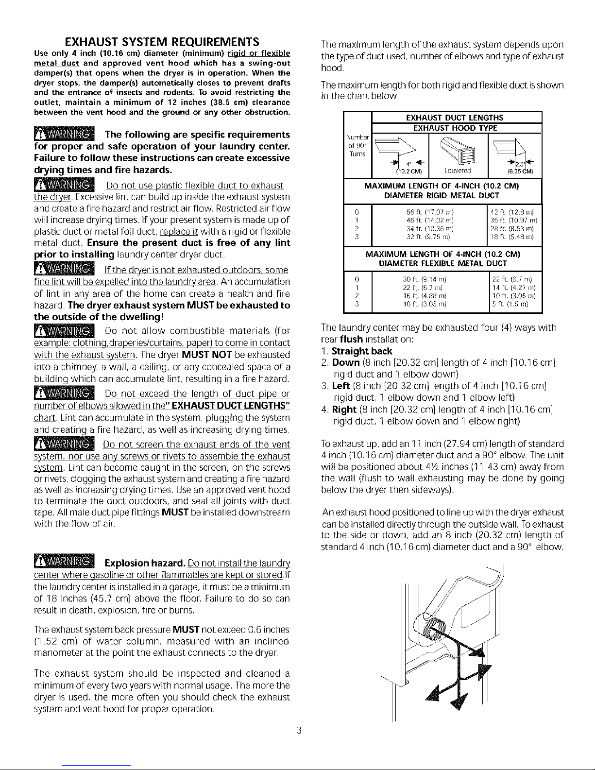
The maximum length ofthe exhaust system depends upon
the type of duct used, number of elbows and type of exhaust
hood,
Themaximum length for both rigid and flexible duct isshown
in the chart below.
EXHAUST DUCT LENGTHS
EXHAUST HOOD TYPE
Tums 25"
Louvered (6
0
1
2
3
MAXIMUM LENGTH OF 4-INCH (10.2 CM)
DIAMETER RIGID METAL DUCT
56 tt (1707 m) 42 [t (128 m)
46 tt (1402 m) 36 tt (1097 m)
34 tt (1036 m) 28 [t (853 m)
32 ft (975 m) 18 ft (548 m)
MAXIMUM LENGTH OF 4-INCH (10.2 CM)
DIAMETER FLEXIBLE METAL DUCT
0 30 ft (914 m) 22 ft (67 m)
1 22 ft {67 m) 14tt (427 m)
2 16 tt (488 m) 10 tt (305 m)
3 10 tt (30S m) S tt (15 m)
The laundry center may be exhausted four (4) ways with
rear flush installation:
1 Straight back
2. Down (8 inch [20.32 cm[ length of 4 inch [10.16 cm]
rigid duct and 1 elbow down)
3. Left (8 inch [20.32 cm] length of 4 inch [10.16 cm]
rigid duct, 1 elbow down and 1 elbow left)
4. Right (8 inch [20,32 cm] length of 4 inch [10,16 cm]
rigid duct, 1 elbow down and 1 elbow right)
Toexhaust up, add an 11 inch (27,94 cm) length of standard
4 inch (10,16 cm) diameter duct and a 90° elbow. The unit
will be positioned about 4Y, inches (11.43 cm) away from
the wall (flush to wall exhausting may be done by going
below the dryer then sideways).
An exhaust hood positioned to line up with the dryer exhaust
can be installed directly through the outside wall, ]o exhaust
to the side or down, add an 8 inch (20.32 cm) length of
standard 4 inch (10,16 cm) diameter duct and a 90° elbow,
3
 Loading...