

Frigidaire FFGS3025L, FGS365E, FGS365EC, FGS366E, FGS367FC Installation Instructions Manual
...Page 1
30" GAS SLIDE-IN RANGE INSTALLATION INSTRUCTIONS
(Models with Sealed Top Burners)
INSTALLATION AND SERVICE MUST BE PERFORMED BY A QUALIFIED INSTALLER.
IMPORTANT: SAVE FOR LOCAL ELECTRICAL INSPECTOR'S USE.
READ AND SAVE THESE INSTRUCTIONS FOR FUTURE REFERENCE.
If the information in this manual is not followed exactly, a
fire or explosion may result causing property damage, personal injury
or death.
FOR YOUR SAFETY:
—Do not store or use gasoline or other flammable vapors and liquids in
the vicinity of this or any other appliance.
—WHAT TO DO IF YOU SMELL GAS:
• Do not try to light any appliance.
• Do not touch any electrical switch; do not use any phone in your
building.
• Immediately call your gas supplier from a neighbor's phone. Follow
the gas supplier's instructions.
• If you cannot reach your gas supplier, call the fire department.
—Installation and service must be performed by a qualified installer,
service agency or the gas supplier.
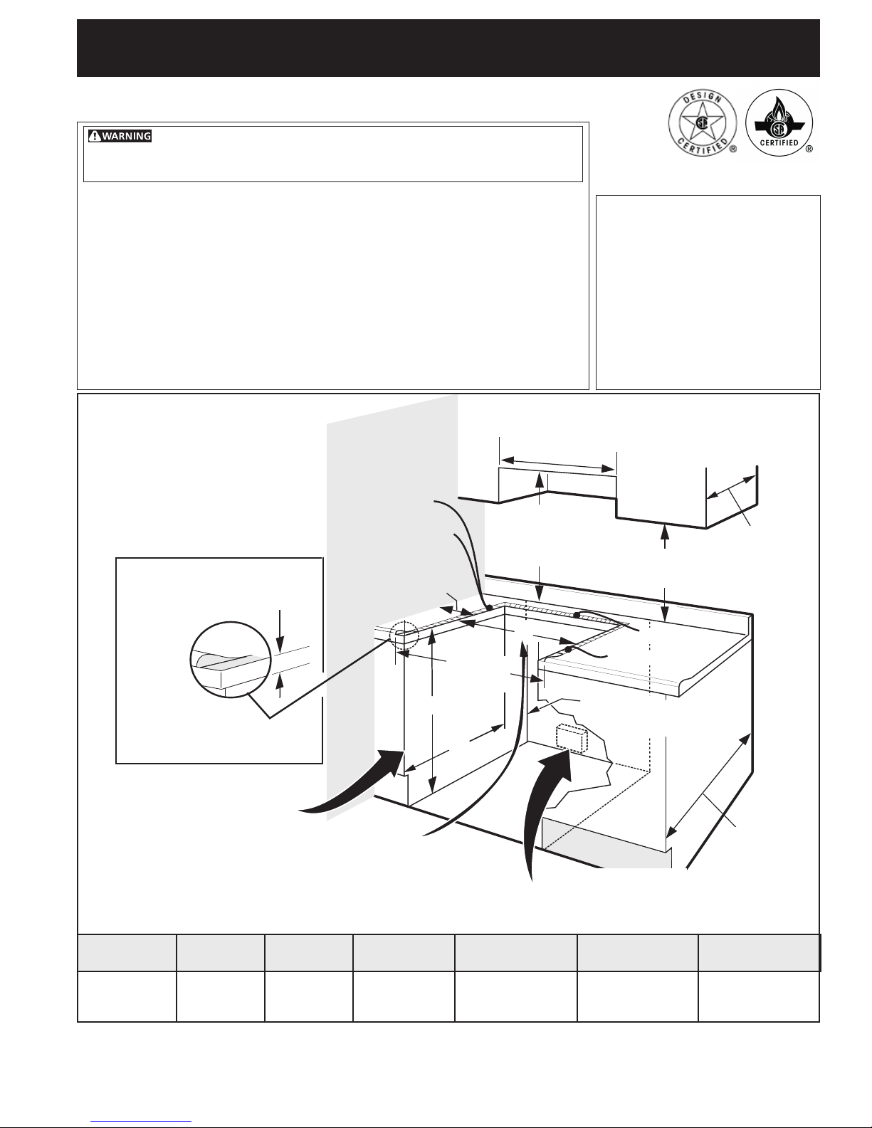
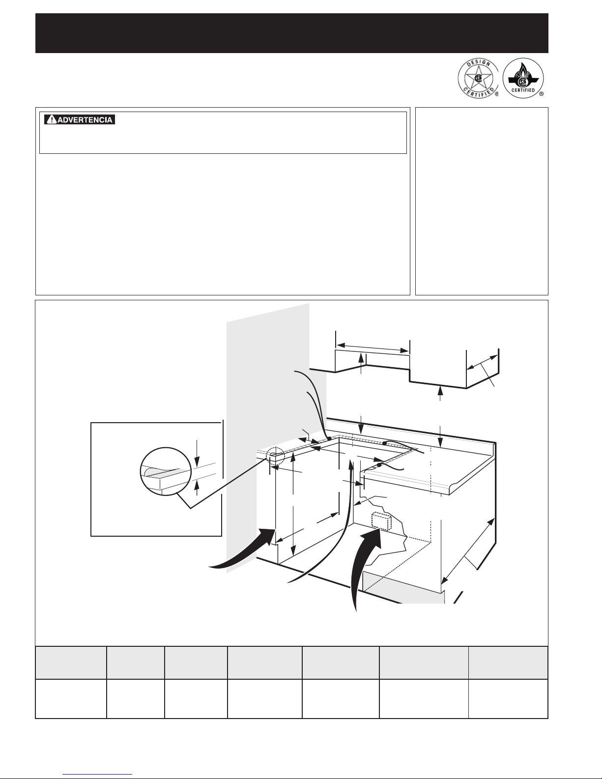
LL
A
W
30" Min.
(76.2 cm Min.)
These surfaces should be flat
& leveled (hatched area).
30" Min.
(76.2 cm) Min. (see
Note 3)
E
Shave
Raised
Edge
to Clear
Space
for a 31½"
(81 cm) Wide
Cooktop.
1 ½" Max.
(3.8 cm Max.)
1/2” Min.
5" Min.
(12.7 cm Min.)
From Wall Both Sides
G
31 1/2"
(81 cm)
Exact
F
Refer to your serial plate for
applicable agency certification
Appliances Installed in the
state of Massachusetts:
This Appliance can only be installed
in the state of Massachusetts by a
Massachusetts licensed plumber or
gasfitter.
This appliance must be installed
with a three (3) foot / 36 in. long
flexible gas connector.
A"T" handle type manual gas valve
must be installed in the gas supply
line to this appliance.
13"
(33 cm)
18" Min.
(45.7 cm) Min.
1/4” min.
1/2” min.
Approx. 1 7/8"
(4.8 cm)
Locate Cabinet Doors 1" (2.5 cm)
Min. from Cutout Opening.
For existing 29" (73.7 cm) cutout width opening,
you must call the Service Center for optional thinner
side panels. Also you must prepare the countertop
edge as shown in the "Countertop Preparation"
section (see page 4).
A. HEIGHT B. WIDTH D. DEPTH TO
35 5/8" (90.5 cm) -
36 5/8" (93cm)
NOTE: Wiring diagram for these appliances are enclosed in this booklet.
Printed in United States
30" (76,2 cm)
C. COOKTOP
WIDTH
31½" (80 cm)
Grounded Jonction Box or Wall Outlet Should Be Located 8"
to 17" (20.3 cm to 43.2 cm) From Right Cabinet and 2" to 4"
E. CUTOUT WIDTH ***
FRONT OF RANGE
28 5/16" (71,9 cm) 30±1/16"
(Countertop and Cabinet)
(76,2±0,15 cm)
1
(5.1 cm to 10.2 cm) From Floor.
F. CUTOUT
DEPTH
21 3/4" (55,2 cm) Min.
22 1/8" (56,2 cm) Max
24" (61 cm) Min. with
backguard
P/N 318201673 (0711) Rev. C
Wiring Diagrams - pages 31-32
36 5/8" (93 cm) Max.
35 5/8" (90.5 cm) Min.
Español – páginas 10-18
Français - pages 19-28
24" Min.
(61 cm Min.)
G. HEIGHT
OF COUNTERTOP
English – pages 1-9
Page 2
30" GAS SLIDE-IN RANGE INSTALLATION INSTRUCTIONS
(Models with Sealed Top Burners)
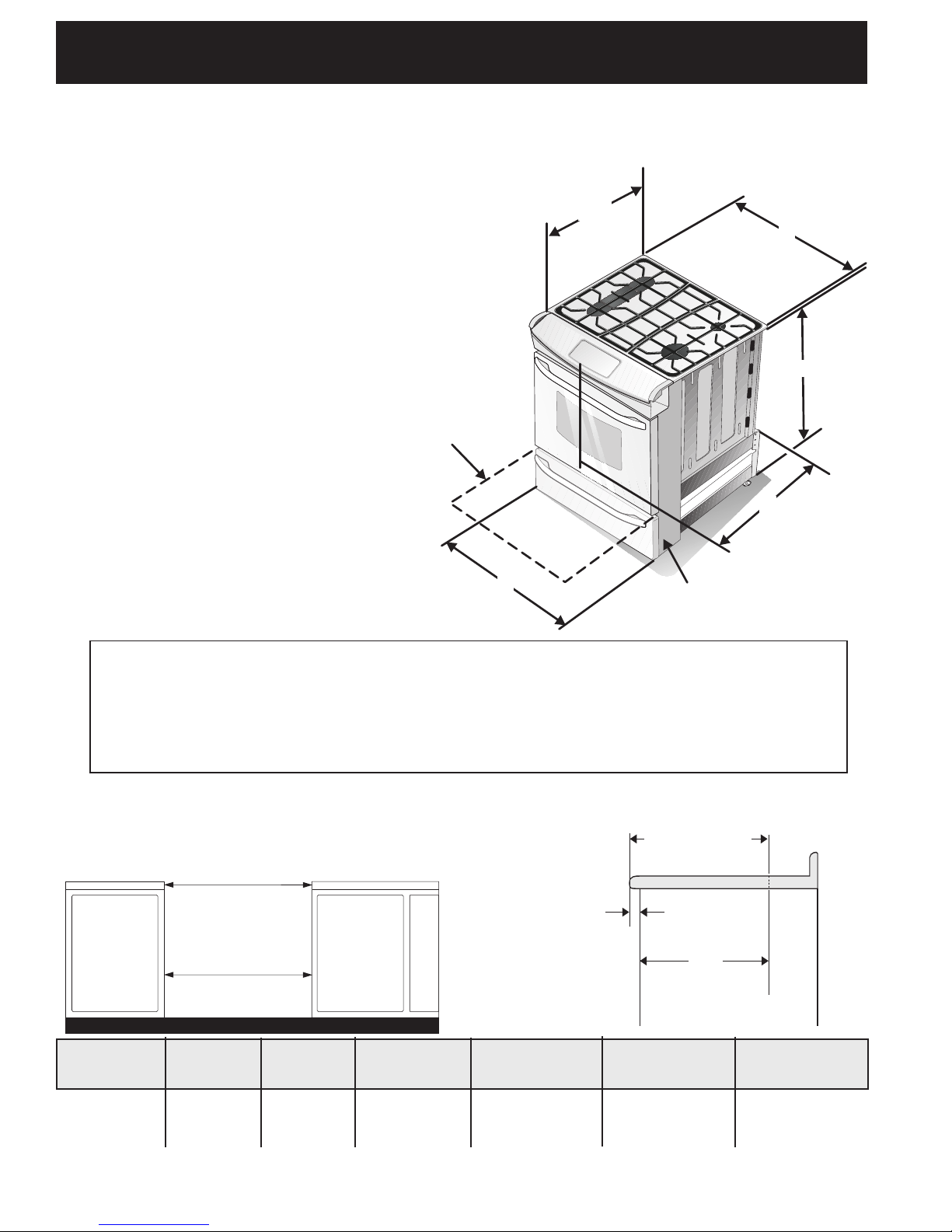
NOTE:
1. Do not pinch the power supply cord or the flexible gas conduit between the range and the wall.
2. Do not seal the range to the side
cabinets.
3. 24" (61 cm) minimum clearance
between the cooktop and the
bottom of the cabinet when the
bottom of wood or metal cabinet
is protected by not less than ¼"
(0.64 cm) flame retardant
millboard covered with not less
than No. 28 MSG sheet metal,
0.015"(0.4 mm) stainless steel,
0.024"(0.6 mm) aluminum, or
0.020" (0.5 mm) copper.
30" (76.2 cm) minimum
clearance when the cabinet is
unprotected.
4. For cutouts below 22 7/8"(58.1
cm), appliance will slightly show
out of the cabinet.
5. Allow at least 19 ¼" (48.9 cm)
clearance for door depth when it
is open.
Figure 1
Door Open
(see note 5)
B
21¾”
(55.25 cm)
C
A
D
Side panel
*IMPORTANT: To avoid cooktop glass breakage for cutout width (E dimension) of
more than 301/16" (76.4 cm), make sure the appliance is centered in the counter
opening while pushing into it. Raise leveling legs at maximum position, insert the
appliance in the counter and then level. Make sure the unit is supported by the
leveling legs not by the cooktop glass itself.
22 7/8" (58.1 cm) min.
IMPORTANT: Cabinet and countertop
width should match the cutout width.
E
E
A. HEIGHT B. WIDTH D. DEPTH TO
35 5/8" (90.5 cm) 36 5/8" (93cm)
30" (76,2 cm) 28 5/16" (71,9 cm)
C. COOKTOP
WIDTH
31½" (80 cm)
FRONT OF RANGE
E. CUTOUT WIDTH ***
(Countertop and
Cabinet)
30±1/16"
(76,2±0,15 cm)
23 1/4" (59.05 cm) max.
(see Note 4)
1 1/8"
(2.86 cm)
FRONT
OF
CABINET
F. CUTOUT
21 3/4" (55,2 cm) Min.
22 1/8" (56,2 cm) Max
24" (61 cm) Min. with
backguard
F
DEPTH
Ref.
35 5/8" (90.5 cm) Min.
G. HEIGHT
OF COUNTERTOP
36 5/8" (93 cm) Max.
2
Page 3
30" GAS SLIDE-IN RANGE INSTALLATION INSTRUCTIONS
(Models with Sealed Top Burners)
Important Notes to the Installer
1. Read all instructions contained in these installation
instructions before installing range.
2. Remove all packing material from the oven
compartments before connecting the gas and electrical
supply to the range.
3. Observe all governing codes and ordinances.
4. Be sure to leave these instructions with the consumer.
5. Note: For operation at 2000 ft. elevations above see
level, appliance rating shall be reduced by 4 percent
for each additional 1000 ft.
Important Note to the Consumer
Keep these instructions with your Use & Care Guide for
future reference.
IMPORTANT SAFETY
INSTRUCTIONS
Installation of this range must conform with local codes
or, in the absence of local codes, with the National Fuel
Gas Code ANSI Z223.1/NFPA .54-latest edition.
This range has been design certified by CSA
International. As with any appliance using gas and
generating heat, there are certain safety precautions you
should follow. You will find them in the Use and Care
Guide, read it carefully.
• Be sure your range is installed and grounded
properly by a qualified installer or service
technician.
• This range must be electrically grounded in
accordance with local codes or, in their absence,
with the National Electrical Code ANSI/NFPA No.
70—latest edition. See Grounding Instructions.
• Before installing the range in an area covered with
linoleum or any other synthetic floor covering,
make sure the floor covering can withstand heat at
least 90°F above room temperature without
shrinking, warping or discoloring. Do not install the
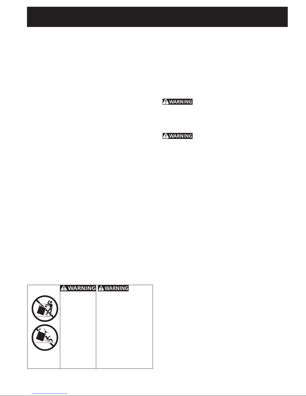
To
• All ranges
can tip.
• Injury to
persons could
result.
• Install anti-tip
device
packed with
range.
reduce the risk of tipping
of the range, the range
must be secured by
properly installed anti-tip
bracket provided with
the range. To check if
the bracket is installed
properly, grasp the top
rear edge of the range
and carefully tilt it
forward to make sure
the range is anchored.
range over carpeting unless you place an insulating pad
or sheet of ¼" (10,16 cm) thick plywood between the
range and carpeting.
• Make sure the wall coverings around the range
can withstand the heat generated by the range.
• Do not obstruct the flow of combustion air at the
oven vent nor around the base or beneath the
lower front panel of the range. Avoid touching the
vent openings or nearby surfaces as they may become
hot while the oven is in operation. This range requires
fresh air for proper burner combustion.
Never leave children alone or
unattended in the area where an appliance is in use.
As children grow, teach them the proper, safe use of all
appliances. Never leave the oven door open when the
range is unattended.
Stepping, leaning or sitting on the
doors or drawers of this range can result in serious
injuries and can also cause damage to the range.
• Do not store items of interest to children in the
cabinets above the range. Children could be seriously
burned climbing on the range to reach items.
• To eliminate the need to reach over the surface
burners, cabinet storage space above the burners
should be avoided.
• Adjust surface burner flame size so it does not
extend beyond the edge of the cooking utensil.
Excessive flame is hazardous.
• Do not use the oven as a storage space. This
creates a potentially hazardous situation.
• Never use your range for warming or heating the
room. Prolonged use of the range without adequate
ventilation can be dangerous.
• Do not store or use gasoline or other flammable
vapors and liquids near this or any other
appliance. Explosions or fires could result.
• In the event of an electrical power outage, the surface
burners can be lit manually. To light a surface burner,
hold a lit match to the burner head and slowly turn the
Surface Control knob to LITE. Use caution when
lighting surface burners manually.
• Reset all controls to the "off" position after using
a programmable timing operation.
FOR MODELS WITH SELF-CLEAN FEATURE:
• Remove broiler pan, food and other utensils
before self-cleaning the oven. Wipe up excess
spillage. Follow the precleaning instructions in the Use
and Care Guide.
• Unlike the standard gas range, THIS COOKTOP IS
NOT REMOVABLE. Do not attempt to remove the
cooktop.
3
Page 4
30" GAS SLIDE-IN RANGE INSTALLATION INSTRUCTIONS
(Models with Sealed Top Burners)
1. Cabinet Construction
To eliminate the risk of cabinet burns and
fire, do not have cabinet storage space above the range.
If there is cabinet storage space above range, reduce risk
by installing a range hood that projects horizontally a
minimum of 5" (12.7 cm) beyond the bottom of the
cabinet.
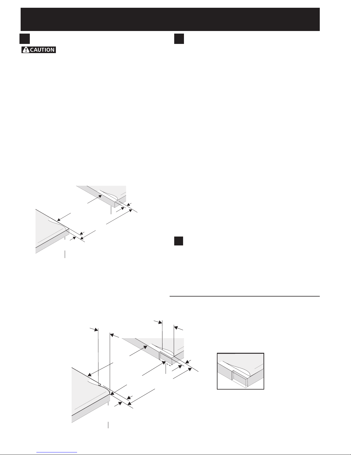
Countertop Preparation
• The cooktop sides of the range fit over the cutout edge
of your countertop.
• If you have a square finish (flat) countertop, no
countertop preparation is required. Cooktop sides lay
directly on edge of countertop.
• Formed front-edged countertops must have molded
edge shaved flat 3/4" (1.9 cm) from each front corner
of opening (Figure 2).
• Tile countertops may need trim cut back 3/4"(1.9
cm) from each front corner and/or rounded edge
flattened (Figure 2).
¾”
Min.
Cutout
Width
31½”
(81 cm)
Formed or tile countertop
¾”
(1.9 cm)
trimmed ¾" (1.9 cm) back at
front corners of countertop
Figure 2
• If the existing cutout width is greater than
30-1/16" (76,4 cm), reduce the ¾" (1.9 cm)
dimension.
• Countertop must be level. Place a level on the
countertop, first side to side, then front to back. If the
countertop is not level, the range will not be level. The
oven must be level for satisfactory baking results.
Cooktop sides of range fit over edges of countertop
opening.
2 3/16”
(5.56 cm)
• For existing
cutout width
of 29" (73.7
cm) (Figure 3):
(1.9 cm)
opening.
29”
(73.7 cm)
30”
(76.2 cm)
31½”
(81 cm)
2. Provide an adequate Gas Supply
When shipped from the factory, this unit is designed to
operate on 4"(10,16 cm) water column (1.0 kPa) Natural
gas manifold pressure. A convertible pressure regulator is
connected to the range manifold and MUST be
connected in series with the gas supply line. If LP/
Propane conversion kit has been used, follow instructions
provided with the kit for converting the pressure
regulator to LP/Propane use.
Care must be taken during installation of range not to
obstruct the flow of combustion and ventilation air.
For proper operation, the maximum inlet pressure to the
regulator should be no more than 14"(35,56 cm) of
water column pressure (3.5 kPa). The inlet pressure to
the regulator must be at least 1" (.25 kPa) greater than
the regulator manifold pressure setting. Examples: If
regulator is set for natural gas 4"(10,16 cm) manifold
pressure, inlet pressure must be at least 5"(12.60 cm); if
regulator has been converted for LP/Propane gas
10"(25,4 cm) manifold pressure, inlet pressure must be
at least 11"(27,9 cm).
Leak testing of the appliance shall be conducted
according to the instructions in step 4.
The gas supply line should be ½" or ¾" I.D. (Interior
Diameter)
3. Seal the openings
Seal any openings in the wall behind the range and in the
floor under the range after gas supply line is installed.
2 3/16”
(5.56 cm)
You must also clear
2 3/16" (5.56 cm) of
material from front
of countertop.
1¼”
(3.2 cm)
1¼”
(3.2 cm)
Formed or tile countertop
trimmed 1¼" (3.2 cm) back at
front corners of countertop
opening.
Figure 3
4
Page 5
30" GAS SLIDE-IN RANGE INSTALLATION INSTRUCTIONS
(Models with Sealed Top Burners)
4. Connect the range to the gas supply
Important: Remove all packing material and
literature from range before connecting gas and
electrical supply.
To prevent leaks, put pipe joint sealant on all external
pipe threads.
Your regulator is in location shown below.
Do not
allow regulator to
rotate on pipe when
tightening fittings.
Figure 4
PRESSURE REGULATOR
LOCATION
Connection to Pressure Regulator
The regulator is already installed on the appliance.
Do not make the connection too tight.
The regulator is die cast. Overtightening may crack the
regulator resulting in a gas leak and possible fire or
explosion.
Manual
Shutoff
Valve
On
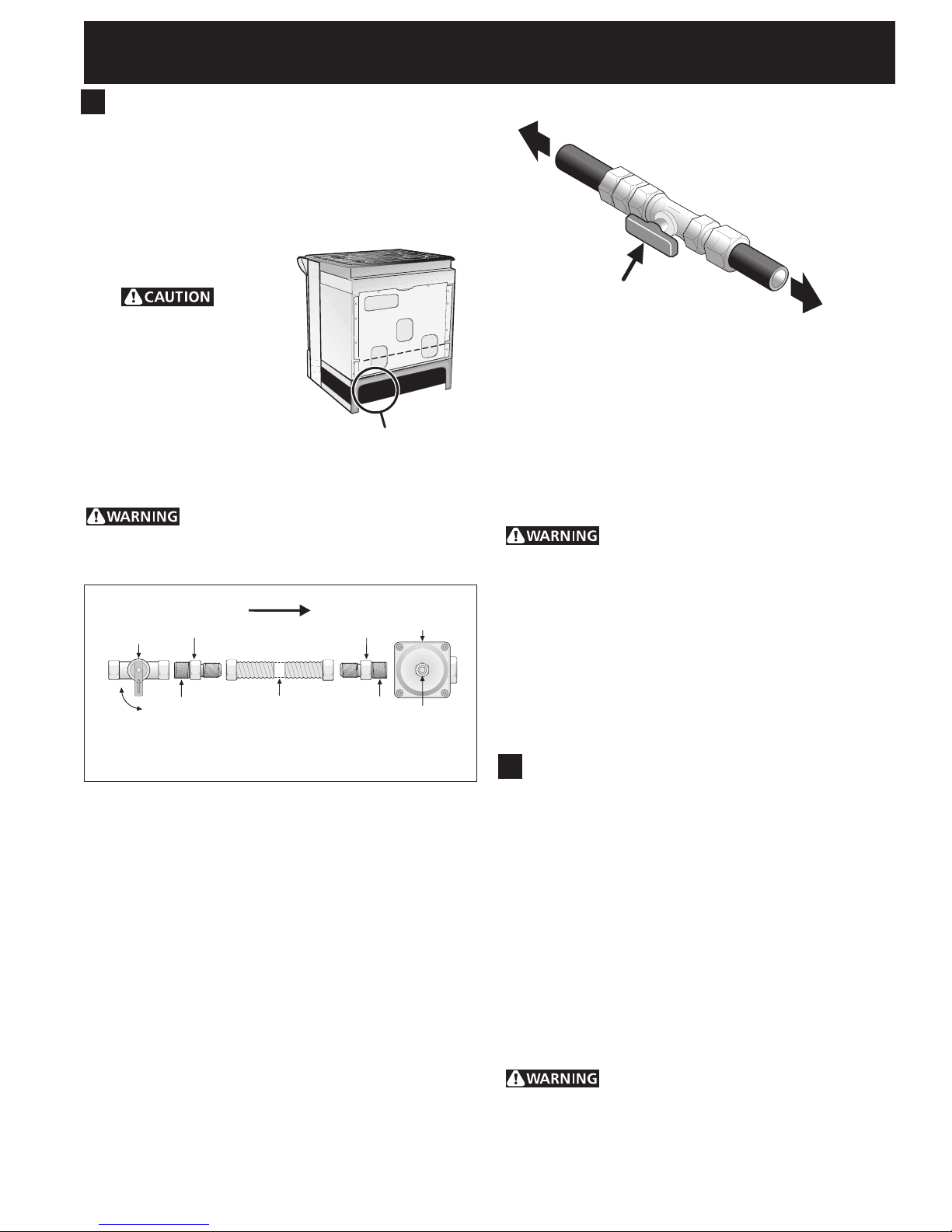
Assemble the flexible connector from the gas supply pipe
to the pressure regulator in the following order:
1. manual shutoff valve (not included)
2. 1/2" nipple (not included)
3. 1/2" flare union adapter (not included)
4. flexible connector (not included)
5. 1/2" flare union adapter (not included)
6. 1/2" nipple (not included)
7. pressure regulator (included)
Use pipe-joint compound made for use with Natural and
LP/Propane gas to seal all gas connections. If flexible
connectors are used, be certain connectors are not
kinked.
The supply line must be equipped with an approved
manual shutoff valve. This valve should be located in the
same room as the range and should be in a location that
allows ease of opening and closing. Do not block access
to the shutoff valve. The valve is for turning on or
shutting off gas to the appliance.
Flare
Union
Nipple Nipple
Off
All connections must be wrench-tightened
GAS FLOW
Flare
Union
Flexible
Connector
Figure 5
Pressure
Regulator
Access
Cap
to appliance
to gas supply line
Shutoff Valve -
Open position
Figure 6
Once regulator is in place, open the shutoff valve in the
gas supply line. Wait a few minutes for gas to move
through the gas line.
Check for leaks. After connecting the range to the gas
supply, check the system for leaks with a manometer. If
a manometer is not available, turn on the gas supply and
use a liquid leak detector (or soap and water) at all
joints and connections to check for leaks.
Do not use a flame to check for leaks
from gas connections. Checking for leaks with a flame
may result in a fire or explosion.
Tighten all connections as necessary to prevent gas
leakage in the range or supply line.
Isolate the range from the gas supply piping system
by closing its individual manual shutoff valve during any
pressure testing of the gas supply piping system at test
pressures equal to or less than 1/2 psig (3.5 kPa or 14"
water column).
5. LP/Propane Gas Conversion
This appliance can be used with Natural gas or LP/Propane
gas. It is shipped from the factory for use with natural gas.
If you wish to convert your range for use with LP/Propane
gas, use the supplied fixed orifices located in a bag
containing the literature marked "FOR LP/PROPANE GAS
CONVERSION." Follow the instructions packaged with
the orifices for surface, oven and broil burners
conversion.
The conversion must be performed by a qualified service
technician in accordance with the manufacturer's
instructions and all local codes and requirements. Failure
to follow these instructions could result in serious injury
or property damage. The qualified agency performing
this work assumes responsibility for the conversion.
Failure to make the appropriate
conversion can result in serious personal injury and
property damage.
5
Page 6
30" GAS SLIDE-IN RANGE INSTALLATION INSTRUCTIONS
(Models with Sealed Top Burners)
6. Electrical Requirements
120 volt, 60 Hertz, properly grounded dedicated circuit
protected by a 15 amp circuit breaker or time delay fuse.
Note: Not recommended to be installed with a Ground
Fault Interrupt (GFI).
Do not use an extension cord with this range.
Grounding Instructions
IMPORTANT Please read carefully.
For personal safety, this appliance must be properly
grounded.
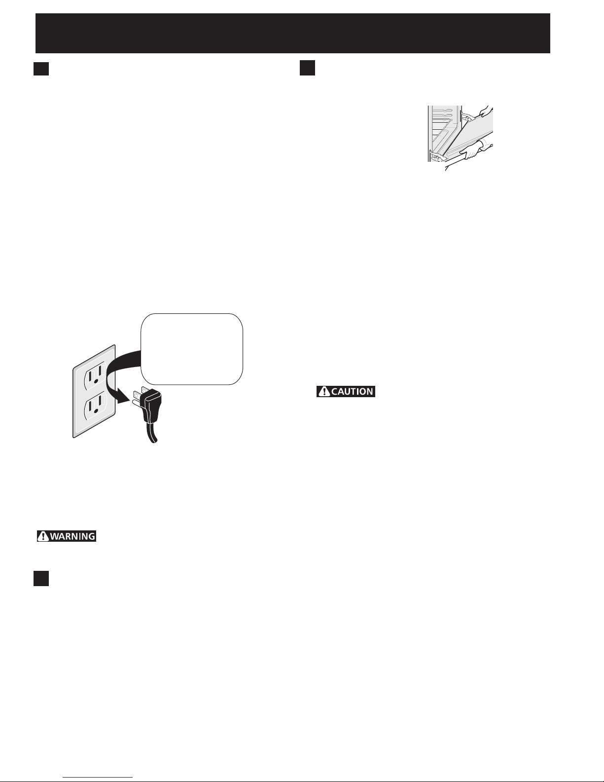
The power cord of this appliance is equipped with a 3prong (grounding) plug which mates with a standard 3prong grounding wall receptacle (see Figure 7) to
minimize the possibility of electric shock hazard from the
appliance.
The wall receptacle and circuit should be checked by a
qualified electrician to make sure the receptacle is
properly grounded.
Preferred Method
Do not, under any
Grounding type
wall receptacle
circumstances, cut,
remove, or bypass
the grounding
prong.
Power supply cord with 3-
Figure 7
prong grounding plug.
Where a standard 2-prong wall receptacle is installed, it
is the personal responsibility and obligation of the
consumer to have it replaced by a properly grounded 3prong wall receptacle.
Do not, under any circumstances, cut or remove the
third (ground) prong from the power cord.
Disconnect electrical supply cord from
wall receptacle before servicing cooktop.
7. Moving the Appliance for
Servicing and Cleaning
Turn off the range line fuse or circuit breakers at the main
power source, and turn off the manual gas shut-off valve.
Make sure the range is cold. Remove the service drawer
(warmer drawer on some models) and open the oven door.
Lift the range at the front and slide it out of the cut-out
opening without creating undue strain on the flexible gas
conduit. Make sure not to pinch the flexible gas conduit at
the back of the range when replacing the unit into the cutout opening. Replace the drawer, close the door and switch
on the electrical power and gas to the range.
8. Range Installation
Important Note: Door removal is not a requirement for
installation of the range, but is an added convenience.
Refer to the Use and Care Guide for oven door removal
instructions.
Standard Installation
1. The range cooktop (or cooktop glass) overlaps the
countertop at the sides and the range rests on the
floor. The cooktop (or cooktop glass) is 31½" (81 cm)
wide.
2. Install base cabinets 30" (76.2 cm) apart. Make sure
they are plumb and level before attaching cooktop.
Shave raised countertop edge to clear 31½" (81 cm)
wide range top rim.
3. Install cabinet doors 31" (78.7 cm) min. apart so they
will not interfere with range door opening.
4. Cutout countertop exactly as shown on page 1.
5. A backguard kit can be ordered through Service
Center.
6. To provide an optimum installation, the top surface of
the countertop must be level and flat (lie on the same
plane) around the 3 sides that are adjacent to range
cooktop. Proper adjustments to make the top flat
should be made or gaps between the countertop and
the range cooktop (or cooktop glass) may occur.
7.
appliance, do not handle or manipulate it by the
cooktop. Manipulate with care.
8. Position range in front of the cabinet opening.
9. Make sure that the cooktop (or cooktop glass) which
overhangs the countertop clears the countertop. If
necessary, raise the unit by lowering the leveling legs.
10.Level the range (see section 9). The floor where the
range is to be installed must be level. Follow the
instructions under "Leveling the Range-Models
Equipped with Leveling Legs".
11.Adjust leveling legs so that the underside of the
cooktop (or cooktop glass) is sitting on the
countertop.
12.Carefully screw in the back leveling leg until the
cooktop (or cooktop glass) overhang touches slightly
the countertop. The cooktop must not support the
unit.
13.Slide the range into the cutout opening.
14.Then carefully screw in the front two leveling legs
(similar to 12) until the cooktop (or cooktop glass)
overhang touches slightly the countertop.
15.If the range is not level, pull unit out and readjust
leveling legs, or make sure floor is level.
Installation For 29" Existing Cutout Width Opening
1. You must replace the original side panels with new and
thinner side panels. These new side panels can be
ordered through a Service Center.
2. Follow instructions supplied with your new side panels to
replace the original side panels with the new ones.
To reduce the risk of damaging your
6
Page 7
30" GAS SLIDE-IN RANGE INSTALLATION INSTRUCTIONS
(Models with Sealed Top Burners)
3. Check if the countertop is prepared for 29" cutout wide
opening at page 3.
4. Install range as in the "Standard Installation"
above.
Installation With Backguard
A backguard kit can be ordered through a Service
Center.
The cutout depth (21 3/4" (55.2 cm) Min., 22 1/8" (56.2
cm) Max.) needs to be increased to 24" (61 cm) when
installing a backguard
Installation With End Panel
An end panel kit can be ordered through a Service
Center.
Installation With Side Panel
A side panels kit can be ordered through a Service
Center. Install cabinet doors 31" (78.7 cm) min. apart so
as not to interfere with range door opening.
section
9. Leveling the Range
Level the range and set cooktop height before
installation in the cut-out opening.
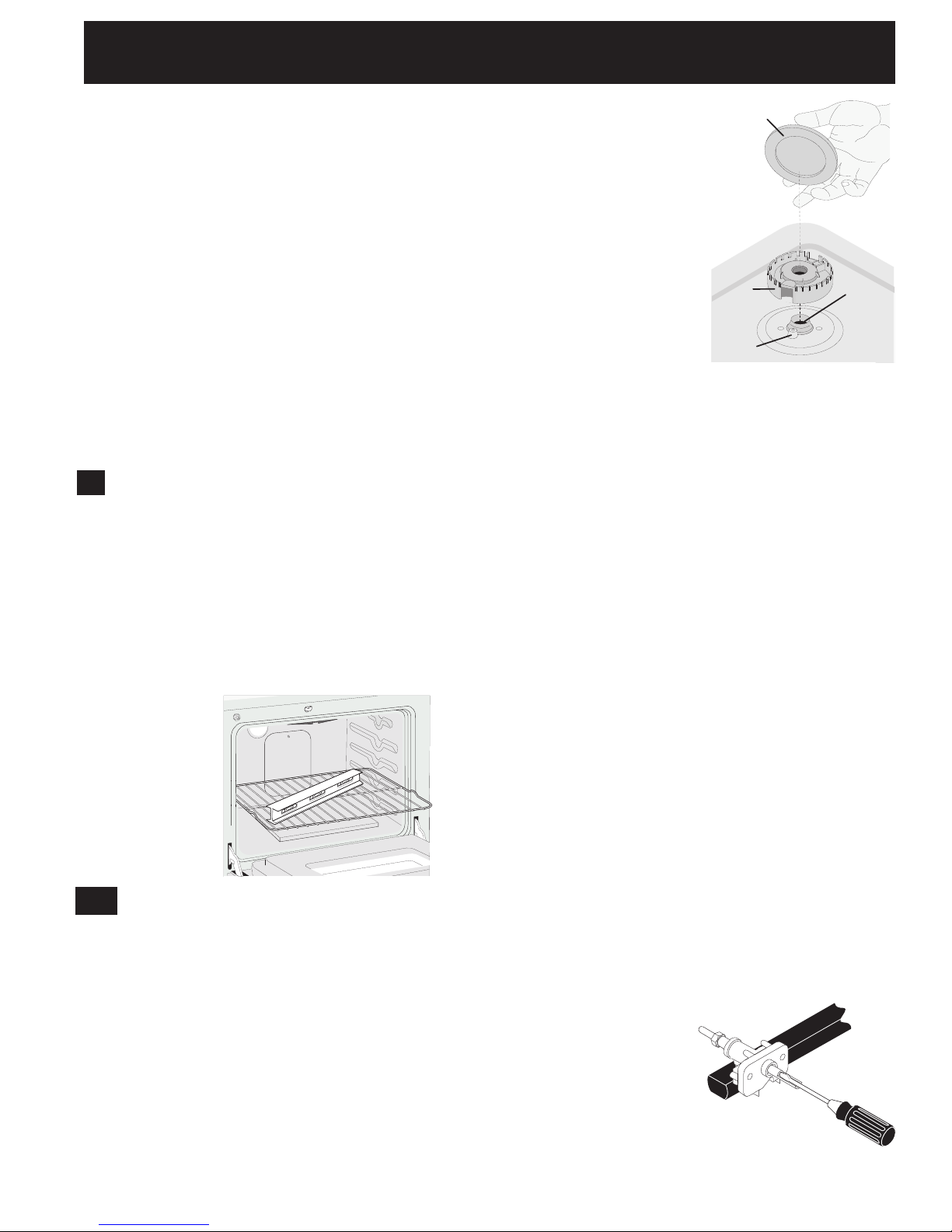
1. Install an oven rack in the center of the oven.
2. Place a level on the rack (see Figure 8). Take 2
readings with the level placed diagonally in one
direction and then the other. Level the range, if
necessary, by adjusting the 4 leg levelers with a
wrench (see Figure 14).
3. Taking care to not damage the countertop, slide
range into cutout opening and double check for
levelness.
Burner Cap
NOTE: There are no
burner adjustments
necessary on this range.
Burner
Base
Electrode
Figure 9
Gas
Opening
10.2 Turn on Electrical Power and Open
Main Shutoff Gas Valve
10.3 Check the Igniters
Operation of electric igniters should be checked after
range and supply line connectors have been carefully
checked for leaks, and range has been connected to
electric power. To check for proper lighting:
a.Push in and turn a surface burner knob to the LITE
position. You will hear the igniter sparking.
b. The surface burner should light when gas is available
to the top burner. Each burner should light within four
(4) seconds after air has been purged from supply
lines. Visually check that burner has lit.
c. Once the burner lights, the control knob should be
rotated out of the LITE position.
There are separate ignition devices for each burner. Try
each knob separately until all burner valves have been
checked.
Figure 8
10. Check Operation
Refer to the Use and Care Guide packaged with the
range for operating instructions and for care and
cleaning of your range.
Remove all packaging from the oven before testing.
10.1 Install Burner Bases and Burner Caps
This range is equipped with sealed burners
as shown (see Figure 9).
a. Unpack burner bases and burner caps.
b. Place burner bases over each gas opening.
c. Make sure the burner is properly aligned and leveled.
Place burner caps over appropriate burner bases.
10.4 Adjust the "LOW" Setting of Surface
Burner Valves (see Figure 10)
a.Push in and turn each control to LITE until burner
ignites.
b. Quickly turn knob to LOWEST POSITION.
c. If burner goes out, readjust valve as follows:
Reset control to OFF. Remove the surface burner
control knob, insert a thin-bladed screw driver into the
hollow valve stem and engage the slotted screw
inside. Flame size can be increased or decreased with
the turn of the screw.
Adjust flame until you
can quickly turn knob
from LITE to LOWEST
POSITION without
extinguishing the
flame. Flame should
be as small as possible
without going out.
7
Figure 10
Page 8
30" GAS SLIDE-IN RANGE INSTALLATION INSTRUCTIONS
(Models with Sealed Top Burners)
10.5 Operation of Oven Burners and Oven
Adjustments
10.5.1 Electric Ignition Burners
Operation of electric igniters should be checked after range
and supply line connectors have been carefully checked for
leaks, and range has been connected to electric power.
The oven burner is equipped with an electric control system
as well as an electric oven burner igniter. If your model is
equipped with a waist-high broil burner igniter, it will also
have an electric burner igniter. These control systems
require no adjustment. When the oven is set to operate,
current will flow to the igniter. It will "glow" similar to a
light bulb. When the igniter has reached a temperature
sufficient to ignite gas, the electrically controlled oven valve
will open and flame will appear at the oven burner. There is
a time lapse from 30 to 60 seconds after thermostat is
turned ON before the flame appears at the oven burner.
When the oven reaches the display setting, the glowing
igniter will go off. The burner flame will go "out" in 20 to
30 seconds after igniter goes "OFF". To maintain any given
oven temperature, this cycle will continue as long as the
display is set to operate.
After removing all packing materials and literature from the
oven:
a) Set the oven to BAKE at 300°F. See Use & Care Guide
for operating instructions.
b) Within 60 seconds the oven burner should ignite. Check
for proper flame, and allow the burner to cycle once.
Reset controls to off.
c) If your model is equipped with a high-waist broiler, set
oven to broil. See Use & Care Guide for operating
instructions.
d) Within 60 seconds the broil burner should ignite. Check
for proper flame. Reset controls to off.
disengage front of oven bottom from oven front
frame, and pull the oven bottom out of the oven.
Remove burner baffle so that burner flame can be
observed.
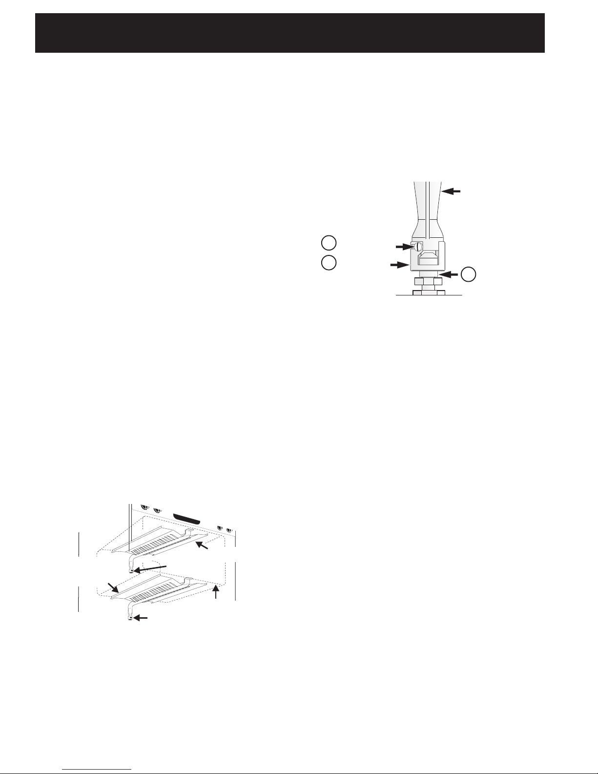
If the flame is yellow, increase air shutter opening size
(see "2" in Figure 12). If the entire flame is blue,
reduce the air shutter opening size.
To adjust frame loosen lock screw (see "3" in Figure
12), reposition air shutter, and tighten lock screw.
Replace oven bottom.
3
Lock Screw
2
Air Shutter
Figure 12
10.5.3 Air Shutter-Broil Burner
The approximate flame length of the burner is 1 inch
(distinct inner cone of blue flame). To determine if the broil
burner flame is proper, set the oven to broil. If flame is
yellow, increase air shutter opening size (see "2" in Figure
12 ). If the entire flame is blue, reduce the air shutter
opening size. To adjust, loosen lock screw (see "3" in Figure
12), reposition air shutter, and tighten lock screw.
Oven Burner Tube
Orifice Hood
1
When All Hookups are Complete
Make sure all controls are left in the OFF position.
Make sure the flow of combustion and ventilation air to
the range is unobstructed.
10.5.2 Air Shutter-Oven Burner
Lower
Oven Baffle
(removable)
Figure 11
The approximate oven burner flame length is 1 inch
(distinct inner cone of blue flame).
To determine if the oven burner flame is proper,
remove the oven bottom and burner baffle and set the
oven to bake at 300°F.
To remove the oven bottom, remove oven hold down
screws at rear of oven bottom. Pull up at rear,
Air Shutter
Waist-High Burner
Air Shutter
Lower Oven Bottom
(removable)
Model and Serial Number Location
The serial plate is located on the oven front frame
behind the oven door (some models) or on the drawer
side frame (some models).
When ordering parts for or making inquiries about your
range, always be sure to include the model and serial
numbers and a lot number or letter from the serial plate
on your range.
Your serial plate also tells you the rating of the burners,
the type of fuel and the pressure the range was
adjusted for when it left the factory.
Before You Call for Service
Read the Before You Call Checklist and operating
instructions in your Use and Care Guide. It may save
you time and expense. The list includes common
occurrences that are not the result of defective
workmanship or materials in this appliance.
Refer to your Use & Care Guide for service phone
numbers.
8
Page 9
30" GAS SLIDE-IN RANGE INSTALLATION INSTRUCTIONS
(Models with Sealed Top Burners)
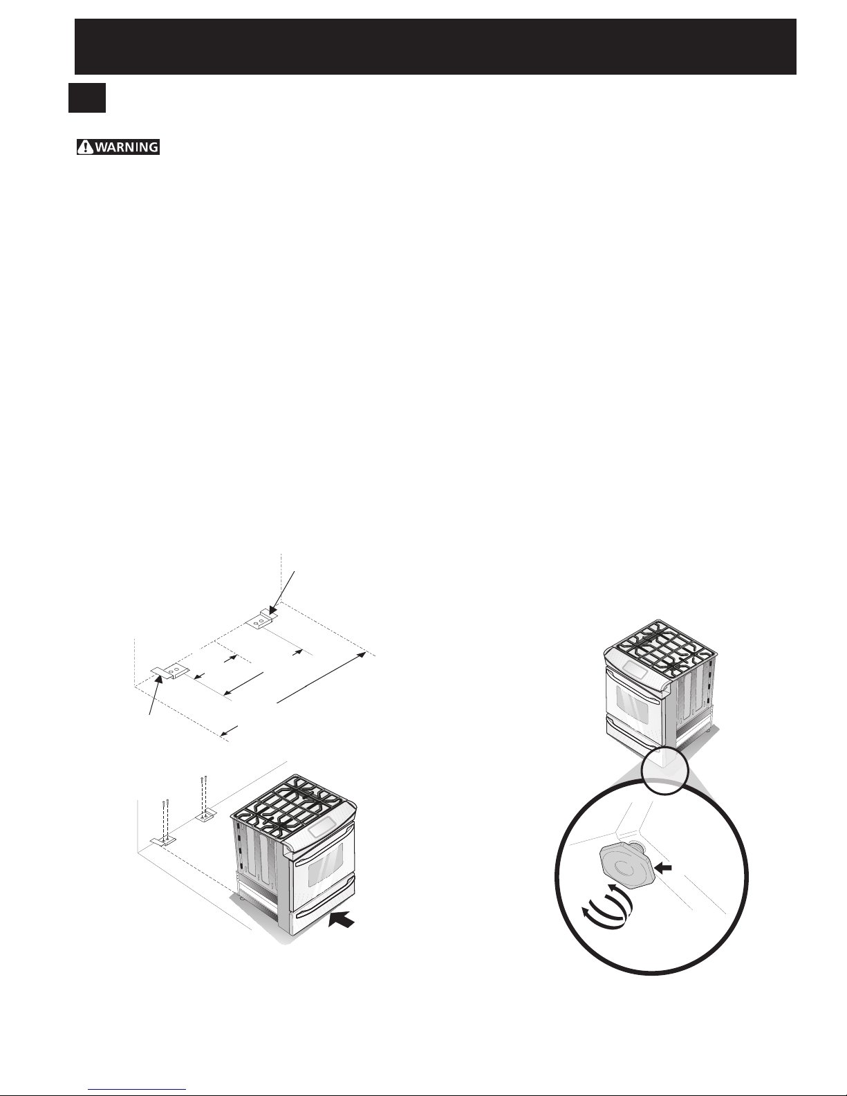
11. Anti-Tip Brackets Installation
Instructions
To reduce the risk of tipping of the range,
the range must be secured to the floor by properly
installed anti-tip brackets and screws packed with the
range. These parts are located in a plastic bag in the
oven. Failure to install the anti-tip brackets will allow the
range to tip over if excessive weight is placed on an
open door or if a child climbs upon it. Serious injury
might result from spilled hot liquids or from the range
itself.
Follow the instructions below to install the anti-tip
brackets.
If range is ever moved to a different location, the anti-tip
brackets must also be moved and installed with the
range. To check for proper installation, see step 5.
Tools Required:
5/16" (0,79 cm) Nutdriver or Flat Head Screwdriver
Adjustable Wrench
Electric Drill
3/16"(0,5 cm) Diameter Drill Bit
3/16"(0,5 cm) Diameter Masonry Drill Bit (if installing in
concrete)
Anti-Tip Bracket
Back Edge of
Range or Rear Wall
Brackets attach to the floor at the back of the range to
hold both rear leg levelers. When fastening to the floor,
be sure that screws do not penetrate electrical wiring or
plumbing. The screws provided will work in either wood
or concrete.
1. Unfold paper template and place it flat on the floor
with the back and side edges positioned exactly
where the back and sides of range will be located
when installed. (Use the diagram below to locate
brackets if template is not available. (Figure 13))
2. Mark on the floor the location of the 4 mounting
holes shown on the template. For easier installation,
3/16" (0.5 cm) diameter pilot holes 1/2" (1.3 cm)
deep can be drilled into the floor.
3. Remove template and place brackets on floor with
turned up flange to the front. Line up holes in
brackets with marks on floor and attach with 4
screws provided. Brackets must be secured to solid
floor. If attaching to concrete floor, first drill 3/16"
(0.5 cm) dia. pilot holes using a masonry drill bit.
4. Level range if necessary, by adjusting 4 leg levelers
with wrench (Figure 14). A minimum clearance of 1/
8" (0.8 cm) is required between the bottom of the
range and the rear leg levelers to allow room for the
anti-tip brackets.
5. Slide range into place making sure rear legs are
trapped by ends of brackets. Range may need to be
shifted slightly to one side as it is being pushed back
to allow rear legs to slide under brackets. You may
also grasp the top rear edge of the range and
carefully attempt to tilt it forward to make sure
range is properly anchored.
Anti-Tip Bracket
(CL = Center line)
CL
9 1/8”
(23.2 cm)
Figure 13
18¼”
(46.4 cm)
28 1/8”
(71.4 cm)
(Rear width of range
with body sides)
Leveling Leg
Raise
Lower
Slide Back
Figure 14
9
Page 10
INSTRUCCIONES DE INSTALACION DE COCINAS DE GAS DE 30"
(Modelos con quemadores sellados)
LA INSTALACION Y EL SERVICIO DEBEN SER EFECTUADOS POR UN INSTALADOR CALIFICADO.
IMPORTANTE: GUARDE ESTAS INSTRUCCIONES PARA USO DEL INSPECTOR LOCAL DE ELECTRICIDAD.
LEA Y GUARDE ESTAS INSTRUCCIONES PARA REFERENCIA FUTURA.
Si la información contenida en este manual no es seguida
exactamente, puede ocurrir un incendio o explosión causando daños
materiales, lesión personal o la muerte.
PARA SU SEGURIDAD:
— No almacene ni utilice gasolina u otros vapores y líquidos inflamables en la proximidad
de éste o de cualquier otro artefacto.
— QUE DEBE HACER SI PERCIBE OLOR A GAS:
• No trate de encender ningún artefacto.
• No toque ningún interruptor eléctrico; no use ningún teléfono en su edificio.
• Llame a su proveedor de gas desde el teléfono de un vecino. Siga las instrucciones del
proveedor de gas.
• Si no logra comunicarse con su proveedor de gas, llame al departamento de bomberos.
— La instalación y el servicio de mantenimiento deben ser efectuados por un instalador
calificado, la agencia de servicio o el proveedor de gas.
PARED
30" Mín.
Aparatos Instalados en el
estado de Massachusetts;
Este Aparato sólo puede ser
instalado en el estado de
Massachusetts por un plomero
o ajustador de gas licenciado
de Massachusett.
Este aparato se debe instalar
con un largo conector flexible
de gas de tres (3) pies/36
pulgadas.
Una válvula manual de gas de
tipo manija de forma de "T" se
debe instalar en la línea del
suministro de gas de este
aparato.
(76.2 cm Mín.)
La superficie debe estar plana y
nivelada (area sombreada).
30" Mín.
(76.2 cm Mín.)
(véa la nota 3)
E
18" Mín.
(45.7 cm) Mín.
1/4” min.
1/2” min.
Approx. 1 7/8"
(4.8 cm)
Acepille el
borde
1 ½" Máx.
(3.8 cm Máx.)
subido a
que deje
espacio
para un
borde 31 1/2"
(81 cm) de
anchura de estufa
1/2” Min.
Mín. 5" (12.7 cm)
de la pared,
ambos lados.
31 1/2"
(81 cm)
Exacto
G
F
13"
(33 cm)
Localise las puertas del armario
1"(2.5 cm) mín del hueco de la
abertura.
NOTA: Para la abertura amplia de corte de 29" (73,7
cm), tiene que llamar al Centro de Servicios y solicitar
paneles laterales opcionales. Despejar el reborde ancho
de la cocina tal como se muestra en la sección
“Preparación de la Mesada “(ver página 13).
A. ALTURA B. ANCHURA
35 5/8" (90.5 cm) -
36 5/8" (93 cm)
30" (76,2 cm) 28 5/16" (71,9 cm) 30±1/16"
C. ANCHURA DE
LA PLANCHA DE
COCINAR
31½" (80 cm)
NOTA: Se adjunta el diagrama de cables de esta cocina al final de este libreta.
Imprimido en los Estados Unidos
D. PROFUNDIDAD A
LA FRENTE DE LA
ESTUFA
10
24" Mín.
(61 cm Mín.)
La caja de empalmes o el enchufe con puesta a tierra debería
situarse de 8" a 17" (20.3 cm a 43.2 cm) del armario
derecho y de 2" a 4" (5.1 cm a 10.2 cm) del suelo.
E. ANCHURA
DE RECORTADO***
(encima y armario)
(76,2±0,15 cm)
F. PROFUNDIDAD DE
RECORTADO
21 3/4" (55,2 cm) Min.
22 1/8" (56,2 cm) Max
24" (61 cm) Min. con un
protector trasero.
P/N 318201673 (0711) Rev. C
Diagrama de la instalación alámbrica - páginas 30-32
G. ALTURA DEL
MOSTRADOR
36 5/8" (93 cm) Max.
35 5/8" (90.5 cm) min.
English – pages 1-9
Español – páginas 10-18
Français -pages 19-28
Page 11

INSTRUCCIONES DE INSTALACION DE COCINAS DE GAS DE 30"
(Modelos con quemadores sellados)
NOTAS:
1. No pellizque el cordón eléctrico o el conducto flexible de gas entre la estufa y la pared.
2. No selle la estufa a los armarios de
lado.
3. Un espacio mínimo de 24" (61 cm)
entre la superficie de la estufa y el fondo
del armario cuando el fondo del armario
de madera o metal está protegido por no
menos de 1/4" (0.64 cm) de madera
resistente al fuego cubierta por una
lámina metálica de MSG, número 28,
0.015" (0.4 mm) de acero inoxidable,
0.024" (0.6 mm) de aluminio, ô 0.02" (0.5
mm) de cobre.
Un espacio mínimo de 30" (76.2 cm)
cuando el armario no está protegido.
4. Para los recortados menos que 22 7/
8’’, el electrodoméstico aparecería
ligeramente en el exterior del armario.
5. Deje por los 19 ¼" (48.9 cm) de
espacio libre para la profundidad de la
puerta cuando esta abierta.
Puerta
abierta
(vea la
nota 5 )
B
21¾”
(55.25 cm)
Panel lateral
C
A
D
Figura 1
*IMPORTANTE: Para el corte a lo ancho (dimensión E) de más de 30 1/16" (76,4 cm) para evitar
que se rompa el vidrio, asegúrese que el artefacto esté centrado en la abertura de la mesada
mientras lo presiona. Levante las patas de nivelación hasta la posición máxima; inserte el artefacto
en la mesada y luego nivele.
Asegúrese de que la unidad esté apoyada en las patas
de nivelación y no en el vidrio liso.
22 7/8" (58.1 cm) min.
IMPORTANTE: El ancho de la cubierta
y el armario debe de ser igual al
ancho del corte.
E
E
A. ALTURA B. ANCHURA
35 5/8" (90.5 cm) -
36 5/8" (93 cm)
30" (76,2 cm) 28 5/16" (71,9 cm) 30±1/16"
C. ANCHURA DE
LA PLANCHA DE
COCINAR
31½" (80 cm)
D. PROFUNDIDAD A
LA FRENTE DE LA
ESTUFA
PARTE DELAN-
TERA DEL ARMARIO
E. ANCHURA
DE RECORTADO***
(encima y armario)
(76,2±0,15 cm)
23 1/4" (59.05 cm) max.
(nota 4)
1 1/8"
(2.86 cm)
F. PROFUNDIDAD DE
RECORTADO
21 3/4" (55,2 cm) Min.
22 1/8" (56,2 cm) Max
24" (61 cm) Min. con un
protector trasero.
F
Ref.
35 5/8" (90.5 cm) min.
G. ALTURA DEL
MOSTRADOR
36 5/8" (93 cm) Max.
11
Page 12

INSTRUCCIONES DE INSTALACION DE COCINAS DE GAS DE 30"
(Modelos con quemadores sellados)
Notas importantes para el Instalador
1. Lea todas las instrucciones contenidas en este manual
antes de instalar la estufa.
2. Saque todo el material usado en el embalaje del
compartimiento del horno antes de conectar el
suministro eléctrico o de gas a la estufa.
3. Observe todos los códigos y reglamentos pertinentes.
4. Deje estas instrucciones con el comprador.
5. Nota: Para la utilización a más de 2 000 pies de
altura, la potencia del aparato deberá ser reducida de
4 por ciento a cada 1 000 pies adicionales.
Nota Importante para el Consumidor
Conserve estas instrucciones y el Manual del Usuario para
referencia futura.
IMPORTANTES INSTRUCCIONES
DE SEGURIDAD
Instalación de esta estufa debe cumplir con todos los
códigos locales, o en ausencia de códigos locales con el
Código Nacional de Gas Combustible ANSI Z223.1/NFPA
.54—última edición.
El diseño de esta estufa ha sido certificado por la CSA
Internacional. En éste como en cualquier otro artefacto
que use gas y genere calor, hay ciertas precauciones de
seguridad que usted debe seguir. Estas serán encontradas
en el Manual del Usuario, léalo cuidadosamente.
• Asegúrese de que la estufa sea instalada y
conectada a tierra en forma apropiada por un
instalador calificado o por un técnico.
• Esta estufa debe ser eléctricamente puesta a tierra
de acuerdo con los códigos locales, o en su
ausencia, con el Código Eléctrico Nacional ANSI/
NFPA No. 70, última edición. Vea las instrucciones
para la puesta a tierra en la página 4.
• Antes de instalar la estufa en un área cuyo piso
este recubierto con linóleo u otro tipo de piso
sintético, asegúrese de que éstos puedan resistir
una temperatura de por lo menos 90°F sobre la
temperatura ambiental sin provocar encogimiento,
deformación o decoloración. No instale la estufa
sobre una alfombra al menos que coloque una plancha
de material aislante de por lo menos 1/4 pulgada,
entre la estufa y la alfombra.
•Todas las
estufas
pueden
volcarse.
•Esto podria
resultar en
lesiones
personales.
•Instale el
dispositivo
antivuelcos
que se ha
empacado
junto con
esta estufa.
Para reducir el riesgo de
que se vuelque la estufa,
hay que asegurarla
adecuadamente colo
candole los soportes
antivuelco que se
proporcionan. Para
comprobar si estos estan
instalados y apretados en
su lugar como se debe,
ase el borde trasero
superior de la estufa y
cuidado samente incline la
hacia adelante para
asegurar que la estufa se
ancle.
• Asegúrese de que el material que recubre las
paredes alrededor de la estufa, pueda resistir el
calor generado por la estufa.
• No obstruya el flujo del aire de combustión en la
ventilación del horno ni tampoco alrededor de la
base o debajo del panel inferior delantero de la
estufa. Evite tocar las aberturas o áreas cercanas de la
ventilación, ya que pueden estar muy calientes durante
el funcionamiento del horno. La estufa requiere aire
fresco para la combustión apropiada de los
quemadores.
Nunca deje niños solos o
desatendidos en un área donde un artefacto está
siendo usado. A medida que los niños crecen,
enséñeles el uso apropiado y de seguridad para todos los
artefactos. Nunca deje la puerta del horno abierta
cuando la estufa está desatendida.
No se pare, apoye o siente en las
puertas o cajones de esta estufa pues puede resultar en
serias lesiones y puede también causar daño a la estufa.
• No almacene artículos que puedan interesar a los
niños en los gabinetes sobre la estufa. Los niños
pueden quemarse seriamente tratando de trepar a la
estufa para alcanzar estos artículos.
• Los gabinetes de almacenamiento sobre la estufa
deben ser evitados, para eliminar la necesidad de
tener que pasar sobre los quemadores superiores
de la estufa para llegar a ellos.
• Ajuste el tamaño de la llama de los quemadores
superiores de tal manera que ésta no sobrepase el
borde de los utensilios de cocinar. La llama
excesiva es peligrosa.
• No use el horno como espacio de almacenaje. Esto
creará una situación potencialmente peligrosa.
• Nunca use la estufa para calentar el cuarto. El uso
prolongado de la estufa sin la adecuada ventilación
puede resultar peligroso.
• No almacene ni utilice gasolina u otros vapores y
líquidos inflamables en la proximidad de éste o de
cualquier otro artefacto eléctrico. Puede provocar
incendio o explosión.
• En caso de una interruptión del servicio eléctrico, es posible
de encender los quemadores de superficie a mano. Para
encender un quemador de superficie, acerque un fósforo
encendido del cabezal del quemador, y gire delicadamente
el botón de control de superficie a LITE (encendido). Tener
cuidado al encender los quemadores a mano.
• Ajuste todos los controles a la posición "OFF"
(apagada) después de haber hecho una operación
con tiempo programado.
PARA MODELOS AUTOLIMPIANTES:
• Saque la asadera, alimentos o cualquier otro utensilio
antes de usar el ciclo de autolimpieza del horno.
Limpie todo exceso de derrame de alimentos. Siga las
instrucciones de prelimpiado en el Manual del Usuario.
• A diferencia de la gama estándar cocinas de gas,
ESTA PLANCHA DE COCINA NO ES MOVIBLE. No
intente quitar la plancha de cocina.
12
Page 13

INSTRUCCIONES DE INSTALACION DE COCINAS DE GAS DE 30"
(Modelos con quemadores sellados)
1. Construcción del armario
Para eliminar el riesgo de quemaduras o
de fuego tratando de alcanzar algo por encima de las
zonas calientes, evite de colocar artículos sobre la cocina.
Si cree necesitar este espacio, el riesgo puede disminuír si
instala un sombrerete que proteja horizontalmente un
mínimo de 5" (12.7cm) sobre la base del armario.
Preparación del mostrador
• Las extremidades de la cocina sobrepasan el borde de
su mostrador.
• Si tiene un mostrador con las extremidades
cuadradas (planas), no se necesita ninguna
preparación del mostrador.
• El reborde de frente de mostradores moldeados
deben tener bordes moldeados a 3/4" (1.9cm) a partir
de cada extremidad de la apertura (Figura 2).
• Los mostradores enazulejos deberán necesitar un
recorte de 3/4" (1.9 cm) a partit de cada extremidad
y/o un borde redondeado aplanado (Figura 2).
Anchura
de hueco
mín.
31½”
(81 cm)
Mostrador moldeado o
¾”
(1.9 cm)
enazulejo recortado 3/4" (1.9 cm)
hacia atrás en las esquinas de
frente de la abertura del
Figura 2
mostrador.
• Si el ancho de la abertura del mostrador es más
grande que 30 1/16" (76,4 cm), ajuste a las
dimensiones como para el 3/4" (1.9).
• Para la Anchura existente del Recorte de el
29"(73.7 cm) (Figura 3):
2 3/16”
2 3/16”
(5.56 cm)
29”
(73.7 cm)
30”
(76.2 cm)
1¼”
(3.2 cm)
(5.56 cm)
1¼”
(3.2 cm)
31½”
(81 cm)
Mostrador moldeado o
enazulejo recortado 3/4" (1.9 cm)
hacia atrás en las esquinas de
frente de la abertura del
mostrador.
Figura 3
• El mostrador deber ser nivelado. Coloque un
nivelador sobre el mostrador, primero de lado a lado y
luego del frente hacia atrás. Si el mostrador no está
nivelado, la cocina no estará nivelada. El horno debe
ser nivelado para tener resultados satisfactorios al
hornear. Las extremidades de la plancha de la cocinar
sobrepasan los bordes de la abertura del mostrador.
¾”
(1.9 cm)
Quite el 2 3/16" de
material de frente a la
parte posteriora.
2. Proporcione un suministro de gas
adecuado
Cuándo se envía de la fábrica, Esta unidad ha sido
ajustada para operar con un múltiple de admisión para
gas natural de 4" (10.16 cm)(1.0 kPa). Un regulador de
presión convertible esta conectado a la válvula
distribuidora y DEBE ser conectado con la tuberia del
suministro de gas. Si el juego de conversión del propano
LP/Propano se ha utilizado, sigue las instrucciones
proporcionadas el juego para convertir el regulador de
presión al uso de LP/Propano.
Se debe de tener cuidado durante la instalación de la
estufa para no obstruir el flujo de aire de combustión y
ventilación
Para la operación apropriada, la máxima presión de
entrada al regulador no debe execeder la presión de una
columna de agua de 14"(35,56 cm) (3.5 kPa). La presión
de entrada al regulador debe ser por lo menos 1" (.25
kPa) más grande que la válvula distribuidora.Ejemplos: Si
regulador se pone para el gas natural con una presión de
4"(10,16 cm), la presión de entrada al regulador debe
ser por lo menos 5"(12.60 cm); si el regulador se ha
convertido para gas LP/Propane 10"(25,4 cm) la presión
de entrada al regulador debe ser por lo menos 11"(27,9
cm).
Un examen de detection de fugas del aparato debe ser
realizado según las instrucciones en el paso 4.
La línea de fuente de gas debe ser de ½" o de ¾".
3. Selle las aperturas
sella todas las aperturas en la pared detrás de la estufa y
en el suelo debajo de la estufa después que la línea del
suministro de gas sea instalada.
4. Conecte la estufa al suministro de gas
Importante: Quite todo el material de embalaje y
literatura de la estufa antes de conectar el gas y la
fuente eléctrica.
Para evitar fugas, aplique
sellador de tuberías en
todas las partes roscadas
machos (exterior) de la
tubería. El regulador se
encuentra en el lugar que
se muestra en la
illustration (Figura 4).
No
permita que el
regulador gire sobre la
tuberiá al apretar las
uniones.
Figura 4
Ubicacion del regulador
de presión
13
Page 14

INSTRUCCIONES DE INSTALACION DE COCINAS DE GAS DE 30"
A
(Modelos con quemadores sellados)
Conecte el Regulador de Presión
El regulador de presión esta ya instalada para la estufa.
No haga la conexión demasiado
apretada. El regulador es de die cast. El apretar
demasiado puede agrietar el regulador dando por
resultado una fuga de gas y un fuego o una explosión.
Valvula de
cierre
manual
Abierto
(On)
Apagado
Boquilla Boquilla
(Off)
FLUJO DEL GAS
Unión
Unión
Conector
flexible
Todas las conexiones deben ser apretadas con
una llave inglesa- Figura 5
Reúna el conector flexible del tubo del suministro de gas
al regulador de la presión en la orden siguiente:
1. Válvula de cierre manual (no incluido)
2. Boquilla de 1/2" (no incluido)
3. 1/2" Adaptador de unión (no incluido)
4. Conector flexible (no incluido)
5. 1/2" Adaptador de unión (no incluido)
6. Boquilla de 1/2" (no incluido)
7. regulador de presión (incluido)
Use sellador para uniones de tuberías hecho para el uso
de gas natural y LP/Propane para sellar todas las
conectiones de gas. Si se utilizan los conectadores
flexibles, aseguresé de que los conectadores no están
enroscados.
La línea del suministro se debe de ser equipada de una
válvula de cierre manual aprobada. Esta válvula se debe
localizar en el mismo cuarto que la estufa y debe estar
en una localización que permita la facilidad de la
abertura y del cierre. No bloquee el acceso a la válvula.
La válvula es para encender o apagar el gas del aparato.
l artefacto
Regulador
de presión
Tapa de
entrada
manómetro. Si un manómetro no está disponible, gire la
fuente de gas y utilice un detector líquido de fugas (o
jabón y agua) en todos los empalmes y conexiones has
la comprobación para fugas.
No utilice una llama para verificar
fugas en las conexiones de gas. Verificar para fugas con
una llama puede tener como resultado un fuego o la
explosión.
Apriete todas las conexiones como necesario para
prevenir fugas de gas en la superficie de la estufa o en
la linea de suministro.
Desconecte la estufa y su válvula de cierre manual
del sistema de tubería del suministro de gas durante
cualquier prueba de presión de ese sistema a presiones
mayores de 1/2 psig (3,5 kPa o 14" columna de agua).
Aísle la estufa del sistema de tubería del suministro
de gas cerrando su válvula de cierre manual durante
cualquier prueba de presión del sistema de tubería del
suministro de gas prueba de presión iguala a o a menos
de 1/2 psig (3,5 kPa o 14" columna de agua).
5. Conversión para uso de Propano
Líquido
Este aparato puede ser usado con gas natural o propano
líquido. Ha sido ajustado en la fábrica para operar con
gas natural solamente.
Si desea convertir su estufa para uso con propano
líquido, use los orificios provistos ubicados en el bolso
que contiene la literatura titulada "FOR LP/PROPANE
GAS CONVERSION." Siga las instrucciones que vienen
con los orificios.
Válvula de cierre -
Figura 6
Abierta
Una vez que regulador está en su lugar, abra la válvula
en la línea del suministro de gas. Espere algunos minutos
para que el gas pueda moverse a través de la línea de
gas.
Compruebe para saber si hay fugas de gas. Después
de conectar la estufa con la fuente de gas, compruebe
el electrodomestico para saber si hay fugas con un
A la linea de gas
La conversión debe ser efectuado por un técnico de
servicio capacitado, de acuerdo con las instrucciones del
fabricante y con todos los códigos y requisitos de las
autoridades correspondentes. El no seguir las
instrucciones podría dar como resultado lesiones graves o
daños a la propiedad. El organismo autorizado para
llevar a cabo este trabajo asume la responsabilidad de la
conversión.
La falta de una conversión apropiada
puede resultar en lesiones graves y daños a la
propiedad.
14
Page 15

INSTRUCCIONES DE INSTALACION DE COCINAS DE GAS DE 30"
(Modelos con quemadores sellados)
6. Requisitos eléctricos
120 voltio, 60 Hertzio, circuito dedicado apropiadamente
puestos a tierra protegido por un circuito de amperio o
fusible de demora de tiempo de 15 amp. Nota: no es
recomendado instalarlo con un interruptor (GFI) de
puesta a tierra.
No utilice una extensión con esta estufa.
Instrucciones de puesta a tierra
IMPORTANTE Por favor lea con cuidado.
Para la seguridad personal, este aparato debe ser
puesto a tierra apropiadamente.
El cable del suministro electrico de esta estufa está
equipado con un enchufe de tres patillas (para puesta a
tierra) que coincida con un enchufe de pared estándar
con puesta a tierra de tres patillas para minimizar la
posibilidad que se produzcan descargas eléctricas.
El cliente deberá encargar a un técnico para asegurarse
de que el enchufe se encuentra debidemente conectado
a tierra y polarizado.
Método preferido
Enchufe de pared
con toma de
tierra
No corte, retire o
deribe, bajo ninguna
circunstancia, la
patilla de la toma de
tierra del enchufe
Cable de suministro
eléctrico con enchufe con
toma de tierra
Figura 7
En lugares en los que aya un enchufe de pared estándar
de dos patillas, el cliente tendrá resposabilidad directa y
la obligacíon de reemplazarlo por un enchufe de pared
de tres patillas debidemente cableado a tierra.
Bajo ninguna circunstancia, corte, retire o deribe la
tercera patilla (de toma de tierra) del cable del
suministro de energía eléctrica.
Desenchufa el cable del suministro de
energía eléctrica del enchufe de pared antes de
mantener la plancha de cocina.
7. La mudanza del aparato para
reparaciones o limpieza
Apague la corriente eléctrica a la estufa a la fuente de
poder principal, y apague la válvula de cierre manual de
gas. Asegúrese de que la estufa esté fresca. Quite el cajón
de servicio (el cajón calentador en algunos modelos) y abre
la puerta del horno. Levante la frente de la estufa y
deslícela fuera de la abertura sin crear tensión desmedida
sobre el conducto flexible de gas. Asegúrese de no
pellizque el conducto flexible de gas detrás de la estufa al
reemplazar la unidad en la abertura. Reemplace el cajón,
cierre la puerta y enciende el gas y la corriente eléctrica a
la estufa.
8. Instalación de la cocina
Nota importante: No es necesario, pero sí es
conveniente, quitar la puerta para instalar el horno.
Consulte las instrucciones para retirar la puerta en la Guía
de Uso y Cuidado.
Instalación estandard.
1. La plancha de cocinar se sobrepone por encima del
mostrador con sus extremidades y la cocina reposa
sobre el suelo. La plancha de cocinar es 31½" (81 cm)
de ancho.
2. Instale la base de los armarios a 30" (76.2 cm) de
espacio entre ellas. Asegúrese que estos esten
verticales y alineados antes de instalar la plancha de
cocinar. Lije el borde del mostrador para obtener las
31½" (81 cm) en la parte superior del mostrador.
3. Instale las puertas del armario a 31" (78,7 cm) de
espacio entre ellas para que no interfieran con la
abertura de la puerta de la cocina.
4. Corte el mostrador exactamente como en la página 9.
5. Puede pedir un juego de repuesto con su
representante.
6. Para una instalación óptima, la superficie superior de la
mesada debe estar nivelada y ser plana (sobre el mismo
plano) en los 3 lados adyacentes a la cocina. Se deben
hacer los ajustes correspondientes para hacer que la
parte superior quede plana, de lo contrario podrán
quedar espacios entre la mesada y la cocina.
7.
artefacto, no lo manipule cerca del vidrio cerámico.
Manipúlelo con cuidado.
8. Coloque la cocina enfrente de la abertura del armario.
9. Asegúrese de que el vidrio que está colgado sobre la
mesada deje despejada la mesada. Si es necesario,
levante la unidad bajando las patas de nivelación.
10.Nivele la cocina (vea Nivelación de la estufa). El piso
donde se instala la cocina debe estar nivelado. Siga las
instrucciones "nivelación de la estufa- modelos
equipado con las patas niveladoras".
11.Ajuste a las piernas de nivelación de manera que la
parte de abajo de la plancha de cocinar está apoyada
contra el mostrador.
12.Atornille con cuidado en la pata de nivelación trasera
hasta que el vidrio que está colgado toque levemente la
mesada. El vidrio debe soportar el peso de la unidad.
13.Luego, atornille con cuidado en las dos patas de
nivelación anteriores (igual a 12) hasta que el vidrio que
está colgado toque levemente la mesada.
14.Deslice la cocina en la abertura para el corte.
15.Si la estufa no está nivelada, arranque el
electrodoméstico y vuelva a ajustar a las piernas o
aseguúrese que el suelo está nivelado.
Instalación para la Anchura existente del Recorte de el
29"(73.7 cm) :
1. Usted debe substituir los paneles laterales reales por los
paneles laterales nuevos y más pequeños. Paneles
laterales puede ser pedido con su representante.
2. Siga la fuente de las instrucciones con sus paneles
laterales nuevos para substituir los paneles laterales
reales por los nuevos.
15
Para reducir el riesgo de dañar su
Page 16

3. Compruebe si el mostrador está preparado para la
abertura
del gas
Tapa de quemador
Base de
quemador
electrodo
4. Instale la estufa.
Instalación con el repuesto.
La profundidad del corte de (21 3/4" (55.2 cm) Min., 22 1/
8" (56.2cm) Max.) necesita ser aumentada a 24" (61 cm)
cuando instala el repuesto.
Instalación con el juego de termino de panel.
Un juego de termino de panel puede ser pedido con su
representante.
Instalación con Paneles Laterales Llenos
Paneles Laterales puede ser pedido con su representante.
Instale las puertas de los armarios a 31" (78.7 cm) de
espacio entre ellas para que no interfieran con la abertura
de la puerta de la cocina.
9. Nivelación de la estufa
Nivele la esufa y ajuste la altura de la estufa antes de
instalarla en la abertura.
1. Coloque una parilla del horno en el centro del horno.
2. Ponga un nivel sobre la parrilla (Figura 8). Tome dos
3. Asegúrese de no dañar al
10. Comprobación del funcionamiento
Consulte el Manual del Usuario incluído con la estufa
para instrucciones de operación y instrucciones para el
cuidado y limpieza de su estufa.
No toque los elementos o quemadores. Pueden estar
bastante calientes para causar quemaduras.
Quite todo el embalaje de la unidad antes de
comprobarla.
10.1 Instala las Bases y las tapas de los
Quemadores
Esta estufa esta equipada con quemadores
sellados como mostrado (vea la Figura 9).
a. Desembale las basas y las tapas de los quemadores.
b. Coloque una basa de quemador sobre cada abertura
c. Asegurese que el quemador está correctamente
INSTRUCCIONES DE INSTALACION DE COCINAS DE GAS DE 30"
(Modelos con quemadores sellados)
abertura amplia del recorte del 29".
lecturas con el nivel puesto diagonalmente en una
dirección y después en la otra. Nivele la estufa, si es
necesario, ajustando las 4 patas niveladoras con una
llave de tuercas (Figura 14).
mostrador, deslice la estufa
dentro de la abertura del
hueco y vuelva a verificar
a la nivelación.
Figura 8
de gas.
alineado y nivelado. Coloque las tapas de los
quemadores sobre las correctas basas de quemadores.
NOTA: No hace falta ningún
ajuste de quemador en esta
estufa.
Figura 9
10.2 Enciende la corriente eléctrica y abre la
válvula principal de cierre.
10.3 Comprobación de los Encendedores
El funcionamiento de los encendedores eléctricos
debe ser comprobado después de que la estufa y los
conectores a la tubería de suministro de gas hayan
sido comprobados para las fugas y la estufa haya sido
conectada eléctricamente. Para comprobar que el
encendido sea correcto:
a. Empuje y gire un bottón control del quemador superior
hasta la posición LITE (encender). Se podría oír el
encendedor haciendo chispas.
b. El quemador se deberá encender en cuatro (4)
segundos para un funcionamiento normal, después de
que el aire haya sido purgado de la tubería de
suministro de gas. Controle visualmente que el
quemador se haya encendido.
c. Después de que el quemador se haya encendido, la
plancha de cocina debe ser girada fuera de la posición
LITE. Cada quemador tiene su encendedor individual.
Controle las perillas separadamente hasta que todas
las válvulas hayan sido controladas.
10.4 Ajuste de la Posición LOW (BAJA) Para la
Válvula del Quemador Superior (Figura 10)
a. Gire el bottón de control a la posición LITE (encender)
hasta que el quemador encienda.
b. Rápidamente gire el bottón de control a la POSICION
MAS BAJA.
c. Si el quemador se apaga, reajuste la válvula de la siguiente
forma: Mueva el control a la posición OFF (apagada). Saque
la perilla de control del quemador superior, inserte un
destornillador plano pequeño en el hueco del vástago del a
válvula hasta enganchar el tornillo interior. El tamaño de la
llama puede ser aumentado o disminuido girando el tornillo.
Ajuste el tamaño de la llama
hasta que pueda pasar
rápidamente de la posición LITE
hasta la posición MAS BAJA sin
que se apague la llama. La
llama debe ser lo más pequeña
posible sin que se apague.
16
Figura 10
Page 17

INSTRUCCIONES DE INSTALACION DE COCINAS DE GAS DE 30"
(Modelos con quemadores sellados)
10.5 Operación de Quemadores del Horno y
Ajustes de Horno
10.5.1 Quemadore de ignicón electrica
La operación de los encendores eléctricos debe de ser
revisada despúes de que la cocina y los conectores de la línea
de suministro haya sido cuidadosamente revisada para
descartar fugas y que la cocina haya sido conectada a la
coriente eléctrica.
El quemador del horno está equipado con un sistema de
control electrico así como un encendedor de quemador de
horno eléctrico. Si su modelo esta equipado con un
quemador de asado central superior, también contará con un
encendedor de quemador eléctrico. Estos sistemas de control
no requieren ajustes. Cuando el horno esta configurado para
operar, la coriente fluirá hacia el encendedor y tendrá un
resplandor de manera similar a una bombilla de luz. Cuando
el encendedor a alcanzado una temperatura suficiente para
encender el gas, la válvula del horno controlada
eléctricamente se abrirá y el fuego aparecerá en el quemador
del horno. Hay un lapso de tiempo de 30 a 60 segundos
depués de que el termostato se enciende y antes de que la
llama aparezca en el quemador del horno. Cuando el horno
alcanza la configuración del dial, el encendedor
resplandeciente se apagará. la llama del quemador
desaparecerá por 20 a 30 segundos después de que el
encendedor se apage. Para mantener qualquier temperatura
de horno dada, este ciclo continuará tanto como el dial (o
visualizador) esté configurado para operar.
Después de retirar todos los materiales del empaque y la
literatura del horno:
a) Fije el horno en HORNEAR (BAKE) a 300°F. Vea la guía de
Uso y Cuidado para conocer las instrucciones de
funcionamiento.
b) En 60 segundos el quemador del horno se encenderá.
Revise que exista un fuego adecuado, y permita que el
quemador cumpla su ciclo una vez. Gire los controladores
hacia off (APAGADO).
c) Si su modelo esta equipado con un asador central superior,
fije el horno en ASAR. Vea la Guía de Uso y Cuidado para
conocer las instrucciones de funcionamento.
d) En 60 segundos el quemador de asar debe de encenderse.
Revise si exista una llama adecuada. Gire los controles
hacia off (APAGADO).
10.5.2 Obturador del Aire - Quemador del horno
La longitud aproximada de la llama del quemador del
horno es 1 pulgada (interior claro, llama azul). Para
determinar si la llama del quemador de horno es la
adecuada, retire el fondo del horno y el deflector del
quemador i fije el horno en la opción hornear a 300°F.
Para retirar el fondo del horno, retire los tornillos de
ajuste del horno en la parte posteior del fondo del
horno. jale hacia arriba, desenganche el frente del fondo
del marco anterior del horno, y jale la base hacia a fuera
de éste. retire el deflector del quemador de manera que
la llama del quemador pueda ser observada.
Si la llama es de color amarillo, aumente el tamaño de la
abertura del obturador de aire (Vea el tamaño "2" en el
gráfico de abjo). Si la llama es de azul claro, reduzca el
tamaño de la abertura del obturador de aire. Para ajustar
un tornillo de cierre flojo (Vea el gráfico "3" de ariba),
vuelva a colocar el obturador de aire, y ajuste el tornillo
de cierre. Reemplace el fondo del horno.
Tubos del
quemador
del horno
Tornillos de
3
seguridad
2
Obturador
de aire
Figura 12
10.5.3 Obturador de aire - Quemador de asado
La longitud aproximada de la llama del quemador de
asado es 1 pulgada (interior claro, llama azul). Para
determinar si la llama del quemador de asado es la
adecuada, poner el horno en la opción asar.
Si la llama es de color amarillo, aumente el tamaño de
la abertura del obturador de aire (Vea el tamaño "2"
en el gráfico de abjo). Si la llama es de azul claro,
reduzca el tamaño de la abertura del obturador de
aire, y ajuste el tornillo de cierre.
Tapa del orificio
1
Después de Terminar la Instalación
Asegúrese de que todos los controles estén en la posición
OFF (apagada).
Asegúrese de que el fluir del aire de combustión y de
ventilación a la estufa no esté obstruido.
Deflector inferior
del horno
(extraíble)
Obturador
de aire
Obturador
de aire
Quemador a la
altura de la
cintura
Parte infeior del
horno (extraíble)
Figure 11
Ubicación del Número de Modelo y de Serie
La placa con el número de serie está ubicada en el
marco delantero del horno detrás de la puerta del horno
(algunos modelos) o detrás del cajón (algunos modelos).
Cuando haga pedidos de repuestos o solicite información
con respecto a su estufa, esté siempre seguro de incluir
el número de modelo y de serie y el número o letra del
lote de la placa de serie de su estufa.
La placa con el número de serie también le da la potencia
nominal de los quemadores, el tipo de combustible y la
presión a la cual fué ajustada la estufa en la fábrica.
17
Page 18

INSTRUCCIONES DE INSTALACION DE COCINAS DE GAS DE 30"
(Modelos con quemadores sellados)
Antes de Llamar al Servicio
Lea la sección Evite Llamadas de Servicio en su Manual del
Usuario. Esto le podrá ahorrar tiempo y gastos. Esta lista
incluye ocurrencias comunes que no son el resultado de
defectos de materiales o fabricación de este artefacto.
Lea la garantía y la información sobre el servicio en su
Manual del Usuario para obtener el número de teléfono
gratuito y la dirección del servicio.
11. Instrucciones de instalación de la
fijación anti-inclinación
Para reducir el riesgo de inclinación de
la cocina, ésta debe ser asegurada hacia el piso con las
fijaciones de anti-inclinación y los tornillos que vienen
con la cocina. Estos componentes se encuentran en el
horno. Si no instala las fijaciones, corre el riesgo que su
cocina pueda inclinarse si pone demasiado peso en ella
o si un niño sube sobre ésta. Esto podría ocasionar
graves heridas causadas por líquidos calientes o por la
propia cocina.
Siga estas instrucciones para instalar las fijaciones de antiinclinación.
Si la cocina es trasladada a otro lugar, las fijaciones de antiinclinación deben también ser trasladados con la cocina. Para
controlar la instalación apropiada, vea el paso número 5.
Herramientas Necesarias:
Llave de tuerca de 5/16"(0,79 cm) o destornillador para
tornillos de cabeza plana
Llave inglesa
Taladro eléctrico
Broca de 3/16"(0,48 cm) de diámetro
Broca para taladro de mampostería de 3/16"(0,48 cm) de
día.(si se está instalando en concreto)
Borde de atras de la
estufa o pared trasera
CL
9 1/8”
(23.2 cm)
Soporte
antivuelco
28 1/8”
(71.4 cm)
Soporte antivuelco
18¼”
(46.4 cm)
(Anchura trasera de la
estufa con los lados)
Los soportes se fijan al suelo en la parte trasera de la
estufa para sujetar ambos niveladores de las patas
traseras. Cuando los esté instalando al piso, asegúrese de
que los tornillos no penetren el alambrado eléctrico o
plomería. Los tornillos provistos pueden utilizarse en
madera o concreto.
1. Desdoble la plantilla de papel y colóquela plana en
el piso con los bordes laterales y el trasero colocados
exactamente donde la parte trasera y los lados de la
estufa serán colocados cuando sea instalada. (Use el
diagrama siguiente para ubicar los soportes si no se
dispone de la plantilla (Figura 13)).
2. Marque en el piso la ubicación de los 4 agujeros de
montaje como se muestra en la plantilla. Para
facilitar la instalación, se pueden taladrar agujeros
piloto de 3/16" (0.5 cm) de día. y 1/2" (1.3 cm) de
profundidad en el piso.
3. Saque la plantilla y coloque los soportes en el piso
con la brida hacia arriba dirigida hacia el frente.
Alinee los agujeros en los soportes con las marcas en
el piso y sujete con los 4 tornillos provistos. Los
soportes deben estar asegurados al piso firme. Si se
va a instalar en piso de concreto, primero debe
taladrar agujeros guía de 3/16" (0.5 cm) de diámetro
usando una broca para taladro de mampostería.
4. Nivele la estufa si es necesario ajustando las cuatro
patas niveladoras con una llave (Ver la Figura 14
abajo). Se requiere un espacio libre mínimo de 1/8"
(0.8 cm) entre la parte inferior de la estufa y los
niveladores de las patas traseras para dejar espacio
para los soportes antivuelco.
5. Deslice la estufa a su lugar asegurándose de que las
patas traseras estén sujetas por los extremos de los
soportes. La estufa puede necesitar ser movida
ligeramente a un lado cuando está siendo empujada
hacia atrás para permitir
que las patas se alineen
con los soportes. Usted
también puede asir el
borde trasero de la cima
de la estufa y
cuidadosamente intentar
voltearla para asegurarse
de que la estufa sea
adecuadamente
anclada.
Figura 13
hacia atras
Pata
niveladora
Levantar
Bajar
Deslizar
Figura 14
18
Page 19

INSTRUCTIONS D'INSTALLATION POUR CUISINIÈRE SUR PIEDS DE 30" À GAZ
(Modèles avec brûleurs fermés)
UN INSTALLATEUR QUALIFIÉ DOIT EFFECTUER L’INSTALLATION ET LE SERVICE
IMPORTANT: CONSERVEZ CES INSTRUCTIONS POUR LES INSPECTEURS LOCAUX.
LISEZ CES INSTRUCTIONS ET CONSERVEZ-LES POUR RÉFÉRENCES ULTÉRIEURES.
Si les instructions de ce manuel ne sont pas suivies à la lettre,
il pourrait en résulter un incendie ou une explosion susceptible de causer des
dommages matériels, des blessures ou même la mort.
POUR VOTRE SÉCURITÉ:
— N’entreposez et n’utilisez pas d’essence ou d’autres produits inflammables à
proximité de cet appareil ou de tout autre appareil.
— QUE FAIRE SI VOUS DÉCELEZ UNE ODEUR DE GAZ:
• Ne tentez d’allumer aucun appareil.
• N’actionnez aucun interrupteur électrique; n’utilisez aucun appareil téléphonique de l’édifice.
• Communiquez immédiatement avec votre fournisseur de gaz en vous servant du téléphone d’un voisin.
Suivez les instructions que le fournisseur vous donnera.
• S’il vous est impossible de rejoindre votre distributeur de gaz, communiquez avec le service d’incendie.
— L’installation et l’entretien doivent être effectués par un installateur qualifié, un service d’entretien ou de
réparation accrédité ou le distributeur de gaz.
R
U
M
30" Min.
(76.2 cm Min.)
Référez-vous à la plaque
signalétique pour la certification
d’agence applicable.
Ces surfaces doivent être planes et à
niveau (région hachurée).
1/2” Min.
5" Min.
1 ½" Max.
Arasez le
(3.8 cm Max.)
dessus du
comptoir
à au
moins
31½"
(81 cm) de
largeur pour l'appareil
Installez les portes de l'armoire à au
moins 1" (2.5 cm) de l'ouverture.
Pour les ouvertures de 29" (73.7 cm) de largeur, vous
devez appeler un centre de service pour commander des
panneaux latéraux plus minces pour l'installation de la
cuisinière. Vous devez aussi suivre les instructions pour la
préparation du dessus de comptoir à la section
"Préparation du dessus de comptoir" (voir page 19).
(12.7 cm Min.)
des deux côtés
31 1/2"
(81 cm) Exact
G
F
30" Min.
(76.2 cm Min.)
(voir la note 3)
18" Min.
13"
(33 cm)
(45.7 cm) Min.
E
1/4” min.
1/2” min.
Approx. 1 7/8"
(4.8 cm)
24" Min.
(61 cm Min.)
La prise murale ou la boîte de jonction doit se situer
entre 8" à 17" (20.3 à 43.2 cm) de l'armoire de droite
et 2" à 4" (5.1 à 10.2 cm) du plancher.
A. HAUTEUR B. LARGEUR D. PROFONDEUR À
35 5/8" (90.5 cm)
- 36 5/8" (93 cm)
NOTE: Le schéma de câblage de l'appareil est inclus à la fin de ce feuillet.
Imprimé aux États-Unis
30" (76,2 cm) 28 5/16" (71,9 cm)
C. LARGEUR DE
LA TABLE DE
CUISSON
31½" (80 cm)
L'AVANT DE LA
CUISINIÈRE
E. LARGEUR DE
DÉCOUPAGE***
(Comptoir & armoire)
30±1/16
(76,2±0,15 cm)
19
F. PROFONDEUR
DE DÉCOUPAGE
21 3/4" (55,2 cm) Min.
22 1/8" (56,2 cm) Max
24" (61 cm) Min. si l'on
installe un dosseret
P/N 318201673 (0711) Rev. C
Scéma de câblage - pages 30-32
G. HAUTEUR DU DESSUS
DE COMPTOIR
36 5/8" (93 cm) Max.
35 5/8" (90.5 cm) Min.
English – pages 1-9
Español - pagínas 10-18
Français - pages 19-28
Page 20

INSTRUCTIONS D'INSTALLATION POUR CUISINIÈRE SUR PIEDS DE 30" À GAZ
(Modèles avec brûleurs fermés)
NOTE:
1.Ne coincez pas le cordon d'alimentation ou le conduit de gaz entre le mur et l'appareil.
2.Ne scellez pas l'appareil aux armoires
latérales.
3.Dégagement minimum de 24" (61 cm)
entre la plaque de cuisson et la bas de
l'armoire du haut lorsque le dessous de
l'armoire en bois ou en métal est protégé
par un celloderme retardateur de flammes
d'un minimum de ¼" (0.64 cm) recouvert
d'une feuille de métal MSG No. 28, d'acier
inoxydable d'un minimum de 0.015" (0.4
mm), d'aluminium de 0.024" (0.6 mm) ou
de cuivre de 0.020" (0.5 mm).
Dégagement minimum de 30" (76.2 cm)
lorsque l'armoire n'est pas protégée.
5.Notez que pour les ouvertures de moins de
22 7/8" (58.1 cm), l'appareil dépassera
légèrement vers l'avant du comptoir.
6.Allouez au moins 19 ¼" (48.9 cm)
d'espace pour permettre l'ouverture de la
porte du four.
Porte ouverte
(voir la note 5)
B
21¾”
(55.25 cm)
C
A
D
Panneau latéral
Figure 1
***IMPORTANT: Pour une largeur de découpage (dimension E) plus grande que 30 1/16" (76.4
cm) et pour éviter un bris de vitre, au moment d'insérer l'appareil dans le comptoir assurez-vous qu'il
est bien centré dans l'ouverture. Levez les pattes de nivellement au maximum, insérez l'appareil dans
le comptoir et ensuite nivelez-le. Assurez-vous que l'appareil est bien supporté par les
pattes de nivellement et non par la surface vitrifiée.
IMPORTANT: La largeur du comptoir et
de l'armoire doit être égale à la largeur
de découpage.
E
DEVANT
DU
CABINET
E
22 7/8" (58.1 cm) min.
23 1/4" (59.05 cm) max.
(see note 4)
1 1/8"
(2.86 cm)
F
A. HAUTEUR B. LARGEUR D. PROFONDEUR À
35 5/8" (90.5 cm)
- 36 5/8" (93 cm)
30" (76,2 cm) 28 5/16" (71,9 cm)
C. LARGEUR DE
LA TABLE DE
CUISSON
31½" (80 cm)
L'AVANT DE LA
CUISINIÈRE
E. LARGEUR DE
DÉCOUPAGE***
(Comptoir & armoire)
30±1/16
(76,2±0,15 cm)
F. PROFONDEUR
DE DÉCOUPAGE
21 3/4" (55,2 cm) Min.
22 1/8" (56,2 cm) Max
24" (61 cm) Min. si l'on
installe un dosseret
G. HAUTEUR DU DESSUS
35 5/8" (90.5 cm) Min.
Ref.
DE COMPTOIR
36 5/8" (93 cm) Max.
20
Page 21

INSTRUCTIONS D'INSTALLATION POUR CUISINIÈRE SUR PIEDS DE 30" À GAZ
(Modèles avec brûleurs fermés)
Notes importantes à l’installateur
1. Lisez toutes les instructions contenues dans ce feuillet
avant d’installer la cuisinière.
2. Enlevez tout le matériel d’emballage des compartiments
du four avant de connecter l’alimentation de gaz et
électrique à la cuisinière.
3. Respectez tous les codes et règlements applicables.
4. N’oubliez pas de laisser ces instructions au
consommateur.
5.
Note: Pour utilisation de l'appareil à 2000 pieds au-dessus
du niveau de la mer, la puissance des brûleurs doit être
reduite de 4% pour chaque 1000 pieds supplémentaires.
Note importante au consommateur
Conservez ces instructions avec le guide de l’utilisateur
pour référence ultérieure.
INSTRUCTIONS DE SÉCURITÉ
IMPORTANTES
Cette cuisinière doit être installée conformément aux
règlements locaux, ou en leurs absences, aux normes
ANSI Z223.1/NFPA .54- dernière édition.
La conception de cette cuisinière a été approuvée par CSA
international. Il faut prendre certaines précautions d’usage
lors de l’utilisation de tout appareil fonctionnant au gaz
naturel ou produisant de la chaleur. Vous trouverez celles-ci
dans votre Guide d’utilisateur, lisez-les avec attention.
• Assurez-vous que votre cuisinière est
correctement installée et mise à la terre par un
installateur ou un technicien d’entretien qualifié.
• Le circuit électrique de cette cuisinière doit être
mis à la terre conformément aux règlements
locaux, ou en leurs absences, au code électrique
ANSI/NFPA No.70-dernière édition. Voir les
instructions de mise à la terre.
• Avant d’installer la cuisinière à un endroit
recouvert de linoléum ou de tout autre
couvre-plancher synthétique, assurez-vous que
celui-ci peut résister à un minimum de 90°F
(32.2°C) de chaleur au-dessus de la température
de la pièce sans se rapetisser, se déformer ou se
décolorer. N’installez pas la cuisinière sur un tapis, à
moins de placer un tampon isolant ou une feuille de
contreplaqué d’une épaisseur de ¼" (0.6 cm) entre la
cuisinière et le tapis.
• Toutes les
cuisinières
peuvent
basculer.
• Des blessures
pourraient
survenir.
• Installer les
amarres qui
accompagnent
la cuisinière.
Pour prévenir tout risque de
basculement de la cuisinière,
cet appareil doit être fixé
correctement au plancher à
l'aide des amarres qui
l'accompagnent. Pour
vérifier si les amarres sont
posées correctement, retirer
le tiroir de rangement et
s'assurer que les amarres
sont enclenchées.
• Assurez-vous que la tapisserie à proximité du four
peut résister à la chaleur générée par la cuisinière.
• Ne bloquez pas la circulation d’air à l’orifice de
ventilation du four ni autour de la base ou sous
le panneau inférieur avant de la cuisinière. Évitez
de toucher les ouvertures de l’orifice de ventilation ou
les surfaces avoisinantes car elles risquent de devenir
chaudes lorsque le four fonctionne. Les brûleurs ont
besoin d’air frais pour assurer une bonne combustion.
Ne laissez jamais les enfants
seuls ou sans surveillance près d’un appareil en
fonctionnement. Apprenez-leur à utiliser les appareils
électroménagers de façon sécuritaire et appropriée. Ne
laissez jamais la porte du four ouverte lorsque la
cuisinière est sans surveillance.
Le fait de monter sur la porte
ou le tiroir de cette cuisinière, de s’y appuyer ou de
s’y asseoir peut occasionner des blessures graves,
et endommager l’appareil.
• N’entreposez pas d’objets susceptibles
d’intéresser les enfants dans les armoires situées
au-dessus de la cuisinière. Ils risquent de se brûler
sérieusement s’ils tentent de grimper sur l’appareil.
• Évitez de placer des armoires de rangement
au-dessus des brûleurs afin d’éliminer les gestes
inutiles au-dessus de ceux-ci.
• Réglez la flamme du brûleur pour qu’elle ne
dépasse pas le bord de l’ustensile utilisé pour la
cuisson. Une flamme excessive est dangereuse.
• N’utilisez pas le four à des fins de rangement.
Ceci génère une situation éventuellement dangereuse.
• N’utilisez jamais votre cuisinière pour réchauffer ou
chauffer la pièce. L’utilisation prolongée de la cuisinière
sans une ventilation adéquate peut s’avérer dangereuse.
• Ne gardez pas de produits combustibles, d’essence
et d’autres produits inflammables à proximité de
cet appareil ou de tout autre appareil. Il pourrait en
résulter des explosions ou un incendie.
• Lors d'une panne de courant électrique, les brûleurs de
surface peuvent être allumés manuellement; placez
une allumette allumée près de la tête du brûleur et
tournez lentement le bouton de commande de surface
à la position LITE. Redoublez de prudence si vous
allumez un brûleur de surface manuellement.
• Replacez toutes les commandes à la position arrêt
«off» après l’utilisation d’une fonction programmable
chronométrée.
POUR MODÈLES AYANT UN FOUR AUTONETTOYANT:
• Enlevez la lèchefrite, les aliments et les autres
ustensiles avant de faire un cycle autonettoyant
du four. Essuyez tous les renversements excessifs.
Suivez les instructions pour le pré-nettoyage dans le
Guide de l’utilisateur.
• Comme sur les cuisinières standard à gaz, LA
TABLE DE CUISSON DE CET APPAREIL N'EST PAS
AMOVIBLE. Ne tentez pas de l'enlever.
21
Page 22

INSTRUCTIONS D'INSTALLATION POUR CUISINIÈRE SUR PIEDS DE 30" À GAZ
(Modèles avec brûleurs fermés)
1. Construction de l’armoire
Pour éliminer les risques de
brûlures ou de feu, en étendant le bras au-dessus des
surfaces de cuisson chaudes, évitez d’installer des
armoires au-dessus de ces dernières. Si vous devez en
installer, il est possible de réduire le risque en plaçant
une hotte pour cuisinière qui excède horizontalement
d’un minimum de 5" (12.7 cm) la base de l’armoire.
Préparation du dessus de comptoir
• Les côtés de la plaque de cuisson de la cuisinière
s’ajustent au-dessus du rebord du découpage du
dessus de comptoir.
• Si vous avez un dessus de comptoir au fini carré
(plat), aucune préparation n'est requise.
• Les dessus de comptoir au rebord avant moulé
doivent être aplanis de ¾" (1.9 cm) à chaque coin
avant de l’ouverture (Figure 2).
• Il est possible qu’il soit nécessaire d’araser de ¾" (1.9
cm) les dessus de comptoir en mosaïque à chaque
coin avant et/ou d’aplanir le rebord arrondi (Figure 2).
¾”
Largeur de
découpage
minimale
31½”
(81 cm)
Dessus de comptoir moulé ou en
mosaïque aplani de ¾" (1.9 cm) aux
¾”
(1.9 cm)
rebords avant de l'ouverture de
dessus de comptoir.
Figure 2
• Si la largeur du dessus de comptoir est
supérieure à la largeur minimum requise, ajustez
en conséquence le ¾" (1.9 cm).
• Le dessus de comptoir doit être à niveau. Placez
un niveau sur le dessus de comptoir, d’abord de
chaque côté, et ensuite du devant à l’arrière. Si le
dessus de comptoir n’est pas horizontal, la cuisinière
ne le sera pas non plus. Le four doit être à
l’horizontale pour obtenir des résultats de cuisson
satisfaisants.
• Pour les découpages actuel de 29" (73.7 cm) de
large (Figure 3)
2 3/16”
(5.56 cm)
29”
(73.7 cm)
(1.9 cm)
2 3/16”
(5.56 cm)
2. Alimentation en gaz – Installation
Cet appareil a été conçu en usine pour fonctionner au
gaz naturel avec une pression d’admission de 4"
cm) de colonne d’eau (1.0 kpa). Un régulateur de
pression convertible est branché avec la rampe à gaz de
la cuisinière, et DOIT RESTER connecté en série avec le
tuyau d’alimentation. Si un kit de conversion au gaz
propane est utilisé, suivez les instructions de conversion
comprises dans le feuillet fourni pour convertir le
régulateur pour être utilisé avec le gaz propane.
Une attention particulière doit être prise lors de
l'installation de l'appareil pour ne pas obstruer la prise
d'air pour la combustion et le conduit de ventilation de
l'appareil.
Pour un fonctionnement normal, la pression intérieure
maximale au régulateur ne doit pas être supérieure à
(35,56 cm) (3.5 kpa) de pression de colonne d’eau.
14"
La pression d’admission au régulateur doit être
supérieure d’au moins un pouce (ou de .25 kpa) au
régulateur ajusté à la rampe à gaz. Pour le gaz naturel,
le régulateur étant ajusté à 4"
(10,16 cm) de pression
(1.0 kpa), la pression d’admission doit être d’au moins 5
"
(12,7 cm) de colonne d’eau (1.25 kpa). Pour le gaz
propane, le régulateur étant ajusté à 10"
(25,4 cm) de
pression (2.5 kpa), la pression d’admission doit être d’au
moins 11 po (27,9 kpa).
La ligne d’alimentation doit être munie d’un robinet
d’arrêt approuvé (voir Figure 6). Ce robinet doit se
trouver dans la même pièce que la cuisinière et à un
endroit qui permette de l’ouvrir et de le fermer
facilement. Ne bloquez pas l’accès au robinet d’arrêt. Il
est destiné à ouvrir et à fermer l’alimentation en gaz de
l’appareil.
Les tests pour vérifier les fuites de gaz doivent être faits
selon les instructions de l'étape 4.
La ligne de gaz doit être de ½" (1.3 cm) ou de ¾" (1.9
cm).
3. Scellez les ouvertures
Scellez toutes les ouvertures dans le mur à l'arrière de la
cuisinière ainsi que celles dans le plancher sous l'appareil
une fois que la ligne de gaz est installée.
Enlevez 2 3/16"(5.6 cm) de
matériel à l'avant du comptoir.
1¼”
(3.2 cm)
(10,16
30”
(76.2 cm)
1¼”
(3.2 cm)
31½”
(81 cm)
Figure 3
Dessus de comptoir moulé ou en
mosaïque: aplanir 1¼" (3.2 cm) aux
rebords avant de chaque côté.
22
Page 23

INSTRUCTIONS D'INSTALLATION POUR CUISINIÈRE SUR PIEDS DE 30" À GAZ
(Modèles avec brûleurs fermés)
4. Branchez le gaz à la cuisinière
Important: Enlever tout le matériel d’emballage des
compartiments du four avant de brancher l’alimentation à
gaz et électrique à la cuisinière.
Afin de prévenir les fuites, utilisez des pâtes à joints de
tuyauterie fabriquées pour utilisation avec gaz naturel et
propane.
Le régulateur est situé tel que montré ici.
Ne
laissez pas le régulateur
glisser sur le tuyau lors
du branchement.
Figure 4
Branchement du régulateur de pression
Le régulateur est installé à l'appareil.
Ne serrez pas trop les raccords. Le
régulateur est moulé sous pression. Un serrage excessif
pourrait le fissurer et provoquer une fuite de gaz
susceptible de causer un incendie ou une explosion.
Robinet
d’arrêt
manuel
Allumé
Adapteur
de raccord
évasé
Mamelon
Arrêté
Tous les branchements doivent être serrés
à l'aide d'une clé à ouverture fixe
Assemblez le connecteur flexible du conduit
d’alimentation en gaz au régulateur de pression dans
l’ordre qui suit
1. robinet d’arrêt manuel (non-inclus)
2. ½" mamelon (non-inclus)
3. ½" adaptateur de raccord évasé (non-inclus)
4. connecteur flexible, (non-inclus)
5. ½" adaptateur de raccord évasé (non-inclus)
6. ½" mamelon (non-inclus)
7. régulateur de pression. (inclus)
DÉBIT
DU GAZ
Flexible
Connector
Figure 5
Emplacement du
régulateur
Adapteur
de raccord
évasé
Mamelon
Régulateur
de pression
Couvercle
d’accès
Utilisez des pâtes à joints de tuyauterie fabriquées pour
utilisation avec gaz naturel et propane, pour sceller les
connexions de gaz. Si des connecteurs flexibles sont
utilisés, assurez-vous qu’ils ne sont pas tordus.
La ligne de gaz doit être munie d'un robinet d'arrêt
manuel approuvé. Ce robinet doit être installé dans la
même pièce que l'appareil et doit être facile d'accès.
Ne bloquez l'accès au robinet. Ce robinet permet
d'arrêter ou de permettre l'alimentation en gaz à la
cuisinière.
Vers l’appareil
Vers la ligne de gaz
Robinet d’arrêt
manuel - Ouvert
Figure 6
Une fois le régulateur en place, ouvrez le robinet de la
ligne d’alimentation en gaz. Attendez quelques minutes
pour permettre au gaz circuler à travers la canalisation
pour le gaz.
Veillez à ce qu’il n’y ait pas de fuites. Après avoir
raccordé l’alimentation en gaz à la cuisinière, à l’aide
d’un manomètre vérifiez si le système ne fuit pas. Si
vous ne disposez pas d’un manomètre, ouvrez
l’alimentation en gaz et utilisez un liquide détecteur de
fuites sur tous les joints et les raccords.
N’utilisez pas de flamme nue pour
vérifier les fuites de gaz. La détection des fuites à l’aide
d’une flamme pourrait provoquer un incendie ou une
explosion.
Resserrez tous les raccords si nécessaire, afin de
prévenir les fuites de gaz dans la plaque de cuisson ou le
tuyau d’alimentation.
Débranchez la cuisinière et fermez son robinet
d’alimentation en gaz lors de toute vérification de
pression du circuit d’alimentation de gaz à une pression
supérieure à 1/2 lb/po2 (3.5 kpa ou 14"
(35,56 cm)
colonne d’eau).
Isolez la cuisinière du réseau d’alimentation en gaz
en fermant son robinet d’arrêt manuel, lors de toute
vérification de pression du circuit d’alimentation en gaz
à une pression inférieure ou égale à 1/2 lb/po2 (3.5 kpa
ou 14 po. colonne d’eau).
23
Page 24

INSTRUCTIONS D'INSTALLATION POUR CUISINIÈRE SUR PIEDS DE 30" À GAZ
(Modèles avec brûleurs fermés)
5. Conversion au gaz propane
Cet appareil fonctionne au gaz naturel ou au gaz
propane. Il est réglé en usine pour fonctionner au gaz
naturel.
Si vous désirez convertir votre cuisinière au gaz propane,
servez-vous des orifices fixes fournis dans l’enveloppe
portant l’inscription «POUR CONVERSION AU GAZ
PROPANE». Suivez les instructions d’installation se
trouvant dans l’enveloppe.
Un installateur qualifié doit effectuer la conversion
conformément aux instructions du fabricant et à tous les
codes et règlements applicables. Si ces instructions ne
sont pas suivies à la lettre, il pourrait en résulter de
sérieuses blessures corporelles ou des dommages
matériels. L’entreprise d’installation qualifiée qui
effectue ce travail assume la responsabilité de la
conversion.
Si on n’effectue pas la conversion
correctement, il pourrait en résulter des blessures
corporelles et des dommages matériels.
6. Branchez le courant électrique à
la cuisinière
Circuit de dérivation de 120 volt, 60 Hertz, avec mise à
la terre appropriée, protégé par un disjoncteur de 15
ampères ou un fusible temporisé.
N'utilisez pas de cordon de rallonge pour brancher
l'appareil.
Instructions de mise à la terre
IMPORTANT Veuillez lire attentivement.
Pour votre propre sécurité, cet appareil doit être
correctement mis à la terre.
Afin de réduire au minimum les risques de chocs
électriques, le cordon d'alimentation de cet appareil est
muni d'une fiche de contact tripolaire (mise à la terre)
enfichable dans une prise de courant murale tripolaire
standard avec mise à la terre (figure 7).
Il est conseillé de faire vérifier la prise de courant murale
et le circuit par un électricien qualifié, afin de s'assurer
que la prise de courant est correctement mise à la terre.
Dans le cas où il n'y a qu'une prise de courant murale
bipolaire standard, il incombe au client de la remplacer
par une prise de courant murale tripolaire correctement
mise à la terre.
Il est strictement interdit de couper ou d'enlever la
troisième tige (mise à la terre) du cordon
d'alimentation.
Débranchez le cordon d'alimentation
électrique de la prise de courant murale avant de
réparer ou de nettoyer la plaque de cuisson.
7. Déplacement de l'appareil en vue
d'en faire le service ou pour faire du
nettoyage
Coupez l'alimentation électrique de l'appareil à la boîte
des fusibles ou des disjoncteurs et fermez le robinet
manuel d'alimentation à gaz. Défaites la connexion de
la tuyauterie rigide au régulateur. Il n'est pas nécessaire
de défaire cette connexion si un conduit flexible est
utilisé. Assurez-vous que l'appareil est froid. Retirez le
tiroir de rangement, puis ouvrez la porte du four.
Soulevez la cuisinière à l'avant et faites-la glisser hors de
son gîte, tout en évitant de soumettre le conduit à gaz
flexible à des contraintes excessives. Lorsque la
cuisinière est replacée dans son gîte, veillez à ne pas
coincer le conduit à gaz flexible et le câble
d'alimentation électrique derrière l'appareil.
Reconnectez la tuyauterie rigide au régulateur (si
applicable) et vérifier qu'il n'y a pas une fuite de gaz du
joint. Replacez le tiroir, fermez la porte et réalimentez
l'appareil en gaz et en électricité.
Méthode préférée
Il est strictement
interdit de couper ou
d'enlever la
troisième tige (mise
à la terre) du cordon
d'alimentation.
l'appareil est bien mis à
la terre avant de l'utiliser
Figure 7
Assurez-vous que
24
Page 25

INSTRUCTIONS D'INSTALLATION POUR CUISINIÈRE SUR PIEDS DE 30" À GAZ
(Modèles avec brûleurs fermés)
8. Installation de la cuisinière
Note Importante: L'enlèvement de la porte du four n'est pas
requis pour l'installation de l'appareil, mais la facilite
grandement. Référez-vous au manuel d'utilisation
pour connaître les étapes.
Installation Standard
1. La table de cuisson chevauche, de chaque côté, le dessus du
comptoir et la cuisinière repose sur le plancher. La largeur de
la table de cuisson est de 31½" (81 cm).
2. Les armoires sous le comptoir doivent être distantes de 30"
(76.2 cm). Assurez-vous qu’elles sont d’aplomb et de niveau
avant d’y installer la cuisinière. Araser le rebord bombé à
l’extrémité avant du comptoir pour obtenir un ajustement
serré de 31½" (81 cm) entre les bords extérieurs de la table de
cuisson et le comptoir.
3. Distancez les portes des armoires de 31" (78.7 cm) minimum
afin qu’elles n’interfèrent pas avec l’ouverture de la porte du
four.
4. Découpez le comptoir tel que montré à la page 17.
5. Si un dosseret doit être installé, un nécessaire de service (kit)
peut être commandé par l’intermédiaire de votre marchand.
6. Afin d'obtenir une installation maximale, les 3 côtés du
comptoir recevant l'appareil doivent être plat et à niveau. Tous
les ajustements adéquats afin que le comptoir soit plat
doivent être faits sinon des espaces entre l'appareil et le
comptoir peuvent se produire.
7.
ne pas le saisir ou le manipuler par la vitre de la surface de
cuisson. Manipulez-le avec soin.
8. Placez l'appareil devant l'ouverture du comptoir.
9. Assurez-vous que la surface de cuisson vitrifiée allant par
dessus le comptoir est plus haute que le comptoir. Si tel n'est
pas le cas, levez l'appareil en baissant les pattes de nivellement.
10.Nivelez la cuisinière (voir la section 9). Le plancher qui
supporte la cuisinière doit être de niveau.
11.Ajustez les vis de nivellement pour que le dessous de la table
de cuisson repose au dessus du comptoir.
12.Doucement relevez les vis de nivellement arrière afin que la
surface vitrifiée touche à peine le comptoir. La surface vitrifiée
ne doit pas supporter l'appareil.
13.Glissez l'appareil dans l'ouverture du comptoir.
14.Finalement, relevez doucement les vis de nivellement avant
(comme en 11) jusqu'à ce que la surface vitrifiée touche à
peine le comptoir.
15. Si la cuisinière n’est plus de niveau, tirez-la hors du
découpage et réajustez les vis de nivellement ou assurezvous que le plancher est bien au niveau.
Installation pour découpages de 29" (73.7 cm).
1. Vous devez remplacer les moulures latérales actuelles par de
nouvelles moulures plus petites. Vous pouvez commander ces
moulures en appelant à un centre de service.
2. Installez vos nouvelles moulures à la place des moulures
actuelles, en suivant les instructions fournies avec les
Pour éviter d'endommager l'appareil,
nouvelles moulures.
3. Assurez-vous que le dégagement du comptoir est préparé
pour les découpages de 29" (73.7 cm) de large. Voir la
section "Préparation du dessus de comptoir" en page 19.
4. Installez l'appareil dans l'armoire tel que décrit à la section
précédente.
Installation avec un dosseret
La profondeur du découpage de 21¾" (55.2 cm) minimum et
22 1/8" (56.2cm) maximum doit être augmentée à 24" (61 cm)
lorsqu’un dosseret est installé sur l’appareil.
Installation de panneaux latéraux
Distancez les portes des armoires de 31" (78.7 cm) minimum
afin qu’elles n’interfèrent pas avec l’ouverture de la porte du
four.
9. Mise à niveau de la cuisinière
Mettez la cuisinière de niveau et ajustez la hauteur
de la table de cuisson avant de l’installer dans le
découpage du comptoir.
1. Installez une grille au centre du four.
2. Déposez un niveau à bulle sur la grille (voir la figure
8). Prenez 2 lectures en plaçant le niveau en diagonale dans une direction, puis dans l’autre direction. Si
nécessaire, ajustez les vis de nivellement à l’aide
d’une clé (reportez-vous à la figure 14).
3. Glissez délicatement la cuisinière, en faisant attention
de ne pas abîmer le dessus du comptoir, dans le
découpage du comptoir et vérifiez si elle est encore
de niveau.
Figure 8
10. Vérification du Fonctionnement
Référez-vous au Guide de l’utilisateur inclus avec la
cuisinière pour les directives de fonctionnement et pour
l’entretien et le nettoyage de votre cuisinière.
Enlevez tout le matériel d’emballage du four avant de
commencer les essais.
9.1 Mise en place des bases et des
couvercles de brûleurs
Cette cuisinière est munie de brûleurs scellés comme il
est illustré à la figure 9.
A. Déballez les bases et les couvercles de brûleur.
B. Placez les bases de brûleurs au-dessus de chaque
orifice d'alimentation.
C. Vérifiez que le brûleur est correctement aligné et à
niveau. Placez le couvercle sur la base de brûleur
appropriée.
25
Page 26

INSTRUCTIONS D'INSTALLATION POUR CUISINIÈRE SUR PIEDS DE 30" À GAZ
(Modèles avec brûleurs fermés)
NOTE : Aucun
réglage de brûleur
n’est nécessaire
dans ce genre de
cuisinière.
Couvercle
du brûleur
Burner Cap
Base du
Burner
Base
brûleur
Electrode
Électrode
Orifice
Gas
Opening
d'alimentation
en gaz
Figure 9
10.2 Branchez l’alimentation en électricité
et ouvrez le robinet principal
d’alimentation en gaz
10.3Vérifiez les allumeurs
Il faut vérifier le fonctionnement des allumeurs
électriques après que la cuisinière et les raccords du
tuyau d’alimentation aient été eux-mêmes vérifiés
relativement aux fuites et que la cuisinière ait été
branchée à la prise de courant.
Pour vérifier si l’allumage est adéquat :
a. Appuyez sur le bouton de commande d’un brûleur de
surface et tournez-le à la position «LITE». Vous
entendrez les étincelles de l’allumeur électrique qui
allume le brûleur.
b. Le brûleur de surface doit s’allumer lorsque le gaz est
disponible au brûleur supérieur. En fonctionnement
normal, chaque brûleur doit s’allumer dans un délai
de quatre (4) secondes après que l’air ait été purgé
des canalisations d’alimentation. Regardez si le
brûleur est allumé.
c. Une fois le brûleur allumé, le bouton de commande
doit être tourné à une autre position que LITE.
Il existe des dispositifs d’allumage séparés pour chaque
brûleur. Essayez chaque bouton séparément jusqu’à ce
que tous les robinets de brûleur aient été vérifiés.
10.4 Réglez la position LOW des robinets
des brûleurs de surface (voir Figure 10)
1. Appuyez sur une commande et tournez-la à LITE
jusqu’à ce que le brûleur s’allume.
2. Tournez rapidement le bouton à la position la plus
basse (LOW).
3. Si le brûleur s’éteint, ajustez le robinet comme suit:
Remettez le bouton de commande à arrêt (OFF).
Enlevez le bouton de commande du brûleur de
surface, insérez un tournevis à pointe droite fine dans
la tige creuse du robinet et insérez dans la tête de la
vis. La hauteur de la flamme peut être augmentée ou
diminuée en tournant la vis. Ajustez la flamme
jusqu’à ce que vous
puissiez tourner
rapidement le bouton
de LITE à la plus base
position (LOW) sans
éteindre la flamme.
Celle-ci devrait être
aussi minuscule que
possible sans
s’éteindre.
Figure 10
10.5 Fonctionnement et réglage des brûleurs
du four.
10.5.1 Brûleurs à allumage électrique
Le fonctionnement des allumeurs électriques devrait être
vérifié après que la cuisinière et l'arrivée de gaz aient été
vérifiées minutieusement pour détecter les fuites et que la
cuisinière ait été branchée au réseau électrique.
Le brûleur du four est muni d'un allumeur électrique ainsi que
d'un système de commande électrique. Si votre modèle est
muni d'un brûleur de rôtisserie à alimentation par prise
unique, il aura également un allumeur électrique. Ces
systèmes de commande ne nécessitent aucun ajustement.
Lorsque le fourneau sera prêt à fonctionner, le courant
parviendra à l'allumeur qui deviendra incandescent et lorsqu'il
aura atteint la température d'ignition du gaz, la valve de
commande du four commandée électroniquement s'ouvrira
et une flamme apparaîtra au brûleur du fourneau. Il y a un
délai de 30 à 60 secondes après que le thermostat soit mis en
position "ON" et le moment que la flamme apparaisse au
brûleur du fourneau. Lorsque le four atteint la température
réglée au cadran, l'allumeur s'éteint. La flamme du brûleur
s'éteint entre 20 et 30 secondes après que l'allumeur eut été
coupé. Ce cycle continuera pour maintenir toute température
réglée jusqu'à ce que l'indicateur/cadran soit remis à "OFF".
Après avoir enlevé tout matériel d'emballage et la
documentation du four,
a) Réglez le four pour cuire "BAKE" à 300ºF. Voir le Guide
d'utilisation et d'entretien pour les directives d'opération.
b) Le brûleur du four devrait s'allumer en dedans de 60
secondes. Vérifiez si la flamme est convenable, répétez
la procédure une autre fois et remettez le bouton de
commande à la position Arrêt (OFF).
c) Si votre modèle est muni d'un brûleur de rôtisserie à
alimentation par prise unique, réglez le fourneau à
rôtissage (BROIL). Voir le Guide d'utilisation et d'entretien
pour les directives d'opération.
d) Le brûleur de la rôtisserie devrait s'allumer en dedans de
60 secondes. Vérifiez si la flamme est convenable et
remettez le bouton de commande à "OFF".
26
Page 27

INSTRUCTIONS D'INSTALLATION POUR CUISINIÈRE SUR PIEDS DE 30" À GAZ
(Modèles avec brûleurs fermés)
10.5.2 Brûleur du fourneau à clapet d'air
Déflecteur du
bas du
fourneau
(Démontable)
Clapet à air
Clapet à air
Brûleur de rôtisserie
(Modèles à auto-
nettoyage)
Fond du four
(Démontable)
Figure 11
La longueur approximative de la flamme du brûleur du
fourneau est de 1" (25 mm) (centre de flamme bleu distinct).
Pour déterminer si la flamme du brûleur du four est adéquate,
enlevez le fond du four et l'enceinte du brûleur et réglez la
commande du four à 300°F.
Enlevez les vis de maintien à l'arrière du fond du fourneau
pour pouvoir retirer le fond du fourneau. Soulevez à l'arrière,
dégagez le fond avant du cadre du four et retirez le fond du
fourneau hors de celui-ci. Enlevez l'enceinte du brûleur pour
voir la flamme. Si la flamme est de couleur jaune, augmentez
l'ouverture du clapet d'air (voir "2" à la figure 12). Si la
flamme est bleue, réduisez l'ouverture du clapet d'air.
Pour faire le réglage, desserrez la vis de blocage ("3" à la
figure 12), repositionnez le clapet d'air et serrez la vis de
blocage. Replacez le fond du fourneau.
Tuyau du
brûleur du
fourneau
Lorsque tous les raccords sont terminés
Vérifiez que toutes les commandes sont en position d’arrêt
(OFF).
Assurez-vous que la circulation d’air de combustion et de
ventilation à la cuisinière n’est pas obstruée.
Emplacement des numéros de modèle et de
série
La plaque signalétique est située sur le châssis avant du
four, derrière la porte du four (certains modèles) ou sur
le côté du tiroir (certains modèles).
Lorsque vous commandez des pièces ou pour toute
demande de renseignements au sujet de votre cuisinière,
assurez-vous de toujours inclure les numéros de modèle
et de série et un numéro de lot ou une lettre de la
plaque signalétique de votre cuisinière.
La plaque signalétique vous donne également la
capacité des brûleurs, le type de carburant et la pression
à laquelle la cuisinière a été réglée au moment de
l’expédition.
Avant d’appeler le service d’entretien
Révisez la liste de vérifications préventives et les
instructions d’opération dans votre Guide de l’utilisateur.
Vous sauverez probablement du temps et de l’argent.
La liste contient les événements ordinaires qui ne
résultent pas de défectuosités dans le matériel ou la
fabrication de cet appareil.
Référez-vous à votre Guide de l’utilisateur pour les numéros
de téléphone pour nous rejoindre.
Vis de blocage
3
2
Clapet à air
Figure 12
10.5.3Brûleur de la rôtisserie à clapet d'air
La longueur approximative de la flamme du brûleur du
fourneau est de 1" (25 mm) (centre de flamme bleu distinct).
Pour déterminer si la flamme du brûleur de la rôtisserie est
adéquate, réglez le fourneau à "BROIL". Si la flamme est de
couleur jaune, augmentez l'ouverture du clapet d'air (voir
"2" à la figure 12). Si la flamme est bleue, réduisez
l'ouverture du clapet d'air. Pour faire le réglage, desserrez la
vis de blocage ("3" à la figure 12), repositionnez le clapet d'air
et serrez la vis de blocage.
1
Capot d'orifice
27
Page 28

INSTRUCTIONS D'INSTALLATION POUR CUISINIÈRE SUR PIEDS DE 30" À GAZ
(Modèles avec brûleurs fermés)
11. Instructions de sécurité importantes
Pour réduire le risque de
basculement de la cuisinière, protégez-la en installant les
vis et les supports anti-bascules fournis. Ils sont situés
dans un sac de plastique dans le four. Si vous n’installez
pas ces supports anti-bascules, la cuisinière risque de
basculer si un poids excessif est placé sur une porte
ouverte ou si un enfant y grimpe. Les renversements de
liquides chauds ou le basculement de la cuisinière
peuvent provoquer de sérieuses blessures.
Suivez les instructions ci-dessous pour installer les
supports anti-bascules.
Si vous déplacez la cuisinière pour l’installer à un autre
endroit, vous devez également déplacer les supports
anti-bascules pour les installer avec la cuisinière. Voyez
l’étape 5 pour vérifier comment procéder à une
installation correcte.
Outils Requis :
Tourne écrou de 5 /16"(0,79 cm) ou tournevis à tête carrée
Clé à molette
Perceuse électrique
Foret de 3/16"(0,48 cm) de diamètre
Foret de maçonnerie de 3 /16"(0,48 cm) diamètre (si
l’installation se fait dans du béton)
Instructions d’installation des supports
anti-bascules
Les supports anti-bascules se fixent au plancher, à
l’arrière de la cuisinière, pour retenir les deux pieds
niveleurs. En les fixant au plancher, assurez-vous que les
vis ne pénètrent pas dans la plomberie ou le câblage
électrique. Les vis fournies fonctionneront aussi bien dans
du bois que dans du béton.
Extrémité arrière de la
cuisinière ou paroi arrière
Support anti-bascule
1. Dépliez le gabarit de papier et placez-le à plat sur le
plancher, l’endos et les extrémités des côtés
exactement à l’endroit où l’arrière et les côtés de la
cuisinière seront placés lors de l’installation (utilisez le
diagramme ci-dessous pour localiser les supports
anti-bascules si le gabarit de papier n’est pas
disponible (Figure 13)).
2. Tracez sur le plancher l’emplacement des 4 trous de
montage indiqués sur le gabarit. Pour faciliter
l’installation, des trous pilotes d’un ½"(1.3 cm) de
profondeur et 3/16" (0.5 cm) de diamètre peuvent être
percés dans le plancher.
3. Enlevez le gabarit et placez les supports anti-bascules
sur le plancher, le rebord renversé vers l’avant.
Alignez les trous dans les supports anti-bascules avec
les trous tracés sur le plancher et fixez avec les 4 vis
fournies. Les supports anti-bascules doivent être fixés
sur un plancher solide. Si vous les fixez à un plancher
en béton, percez d’abord des trous pilotes de 3/16"
(0.5 cm) de diamètre à l’aide d’un foret à maçonnerie
de 3/16" (0.5 cm) diamètre.
4. Mettez la cuisinière à niveau au besoin, en l’ajustant
avec les 4 pieds niveleurs à l’aide d’une clé à molette
(voir Figure 14). Un dégagement minimum de 1/8"
(0.3 cm) est requis entre le bas de la cuisinière et les
pieds niveleurs arrières pour disposer de suffisamment
d’espace pour installer les supports anti-bascules.
5. Replacez la cuisinière en la faisant glisser, en vous
assurant que les pieds arrière ont été bien agrippés par
les extrémités des supports anti-bascules. Il est possible
que vous ayez à la déplacer légèrement d’un côté en
la repoussant vers l’arrière pour que les pieds arrière
s’alignent avec les supports anti-bascules. Agrippez le
dessus de l’extrémité arrière de la cuisinière et essayez
soigneusement de l’incliner vers l’avant pour vous
assurer que la cuisinière est correctement ancrée.
CL
9 1/8”
(23.2 cm)
Support
anti-bascule
18¼”
(46.4 cm)
28 1/8”
(71.4 cm)
(largeur arrière de la
cuisinière munie de
panneaux latéraux)
Figure 13
Pieds
niveleurs
Pour remonter
Pour baisser
Figure 14
Glisser vers
l'arrière
28
Page 29

INSTRUCTIONS D'INSTALLATION POUR CUISINIÈRE SUR PIEDS DE 30" À GAZ
(Modèles avec brûleurs fermés)
Notes
29
Page 30

WIRING DIAGRAM - SCHÉMA DE CÂBLAGE
30
Page 31

WIRING DIAGRAM - SCHÉMA DE CÂBLAGE
B
BR-14
TEMPERATURE PROBE
SONDA DE TEMPERATURA
SONDE THERMIQUE
V-14
O-14
MOTOR DOOR LATCH
MOTOR DE LOQUETA
DE PUERTA
MOTEUR PORTE VERROU
NC
NO
DOOR SWITCH
INTERRUPTOR DE PUERTA
INTERRUPTEUR PORTE
BR/W-14
v-14
t
SW.A
C
OVEN CIRCUIT//CIRCUITO DE HORNO//CIRCUIT FOUR
BAKE VALVE
VALVULA DE HORNEAR
ELECTRONIC OVEN CONTROL
CONTROL DE HORNO ELECTRONICO
CONTROLE ELECTRONIQUE FOUR
ES 350
15
v-14
V-14
BL/W-14
BL/W-14
P5
R-14
GY-14
DLB
1
Y-14
BL-14
LATCH MOTOR
MOTOR CERROJO
MOTEUR VERROU
BAKE IGNITER
ENCENDIDO DE HORNEAR
ALLUMEUR CUISSON
BROIL IGNITER
ENCENDIDO DE ASAR
ALLUMEUR GRILLAGE
THERMOSTAT
TERMOSTATO
THERMOSTAT
R-14
W-14
BR-14
R-5
HIGH SPEED THERMOSTAT
TERMOSTATO ALTA VELOCIDAD
THERMOSTAT HAUTE VITESSE
BK-14
Y-14
C 1
NC 2
NO 3
VALVE DE CUISSON
BROIL VALVE
VALVULA DE ASAR
VALVE DE GRILLAGE
CONVECTION MOTOR
MOTOR DE CONVECCION
MOTEUR CONVECTION
R-14
BK-5
R-5
W-14
W-14
W-14BL-14
BR-14
FAN MOTOR
MOTOR DE VENTILADOR
MOTEUR VENTILATEUR
W-14
HIGH
ALTA
HAUTE
LOW
BAJA
LENT
W-6
W-14
W-5
LN
R-6
R-6
COLORS/CODIGOS/CODE COULEUR
BK.-BLACK/NEGRO/NOIR
G.-GREEN/VERDE/VERT
W.-WHITE/BLANCO/BLANC
R.-RED/ROJO/ROUGE
O.-ORANGE/NARANJA/ORANGE
Y.-YELLOW/AMARILLO/JAUNE
BR.-BROWN/MORENO/BRUN
BL.-BLUE/AZUL/BLEU
SW.A
LATCH MOTOR
MOTOR DE CERROJO
MOTEUR VERROU
OVEN LAMP
LUZ DE HORNO
LUMIERE FOUR
BK-14
W-14
COOKTOP CIRCUIT / CIRCUITO DE PLANCHA DE COCINAR / CIRCUIT TABLE CUISSON
W-5
N
L2
R-5
POWER CORD
PARA TRANSPORTE
DE FUERZA
CABLE
D`ALIMENTATION
R-14
R-14
R-14
RIGHT REAR IGNITER SWITCH.
INTERRUPTOR ENCENDIDO
TRASERO DERECHO
INTERRUPTEUR ALLUMEUR
R-14
ARRIERE DROIT
RIGHT FRONT IGNITER SWITCH.
INTERRUPTOR ENCENDIDO
FRENTE DERECHO
INTERRUPTEUR ALLUMEUR
AVANT DROIT
R-14
LEFT FRONT IGNITER SWITCH.
INTERRUPTOR ENCENDIDO
FRENTE IZQUIERDO
INTERRUPTEUR ALLUMEUR
AVANT GAUCHE
R-14
LEFT REAR IGNITER SWITCH.
INTERRUPTOR ENCENDIDO
TRASERO IZQUIERDO
INTERRUPTEUR ALLUMEUR
ARRIERE GAUCHE
IGNITER MODULE BOARD
CUARDO DE MODULO DE ENCENDIDO
BLOC CONNECTION ALLUMEUR
LN
R-14
W-14
W-23
QUEMADOR DE ENCENDIDO SUPERIOR
BOUGIE D`ALLUMAGE BRULEUR
W-23
QUEMADOR DE ENCENDIDO SUPERIOR
BOUGIE D`ALLUMAGE BRULEUR
W-23
QUEMADOR DE ENCENDIDO SUPERIOR
BOUGIE D`ALLUMAGE BRULEUR
W-23
QUEMADOR DE ENCENDIDO SUPERIOR
BOUGIE D`ALLUMAGE BRULEUR
TOP BURNER
TOP BURNER
TOP BURNER
TOP BURNER
NC
NO
SW.A
CODE GAUGE TEMP.
CODIGO MEDIDA
CODE CALIBRE
1 18 125 CL1251 3173
2 16 125 CL1251 3173
3 14 125 CL1251 3173
4 12 125 CL1251 3173
5 18 150 EXL-150 3321
6 16 150 EXL-150 3321
7 14 150 EXL-150 3321
8 12 150 EXL-150 3321
9 10 150 EXL-150 3321
10 18 200 SEW-1 3122
11 16 200 SEW-1 3122
12 12 250 3252
13 16 250 3252
14 20 150 EXL-150 3321
15 8 150 EXL-150 3321
16 8 60
17 10 60
18 10 200 SEW-1 3122
19 20 125 CL1251 3173
20 20 200 SEW-1 3122
21 22 125 CL-1251 3173
22 22 150 EXL-150 3321
23 18 200 3573
C
C CSA UL
CAUTION: DISCONNECT CURRENT BEFORE REMOVING REAR COVER.
ATENCION:CORTAR EL CORIENTE ANTES DE REALIZAR EL MANTENIMIENTO DEL ELECTRODOMESTICO.
ATTENTION:COUPEZ L`ALIMENTATION AVANT D`EFFECTUER LA REPARATION.
318271922 REV:B
31
Page 32

WIRING DIAGRAM - SCHÉMA DE CÂBLAGE
32
 Loading...