

Frigidaire FGGF304DLB1, FGGF304DLB3, FGGF304DLF1, FGGF304DLF2, FGGF304DLF3 Installation Guide
...Page 1
INSTALLATION AND SERVICE MUST BE PERFORHED BY A QUALIFIED INSTALLER,
IMPORTANT: SAVE FOR LOCAL ELECTRICAL INSPECTOR'S USE,
READ AND SAVE THESE INSTRUCTIONS FOR FUTURE REFERENCE,
FOR YOUR SAFETY: Do not store or use gasoline or other flammable vapors
and liquids in the vicinity of this or any other appliance.
If the information in this manual is not followed
exactly, a fire or explosion may result causing property damage,
personal injury or death.
FOR YOUR SAFETY:
= Do not store or use gasoline or other flammable vapors and
liquids in the vicinity of this or any other appliance.
= WHAT TO DO IF YOU SMELL GAS:
= Do not try to light any appliance.
= Do not touch any electrical switch; do not use any phone in
your building.
= Immediately cail your gas supplier from a neighbor's phone.
Follow the gas supplier's instructions.
= If you cannot reach your gas supplier, call the fire department.
-- Installation and service must be performed by a qualified
installer, service agency or the gas supplier.
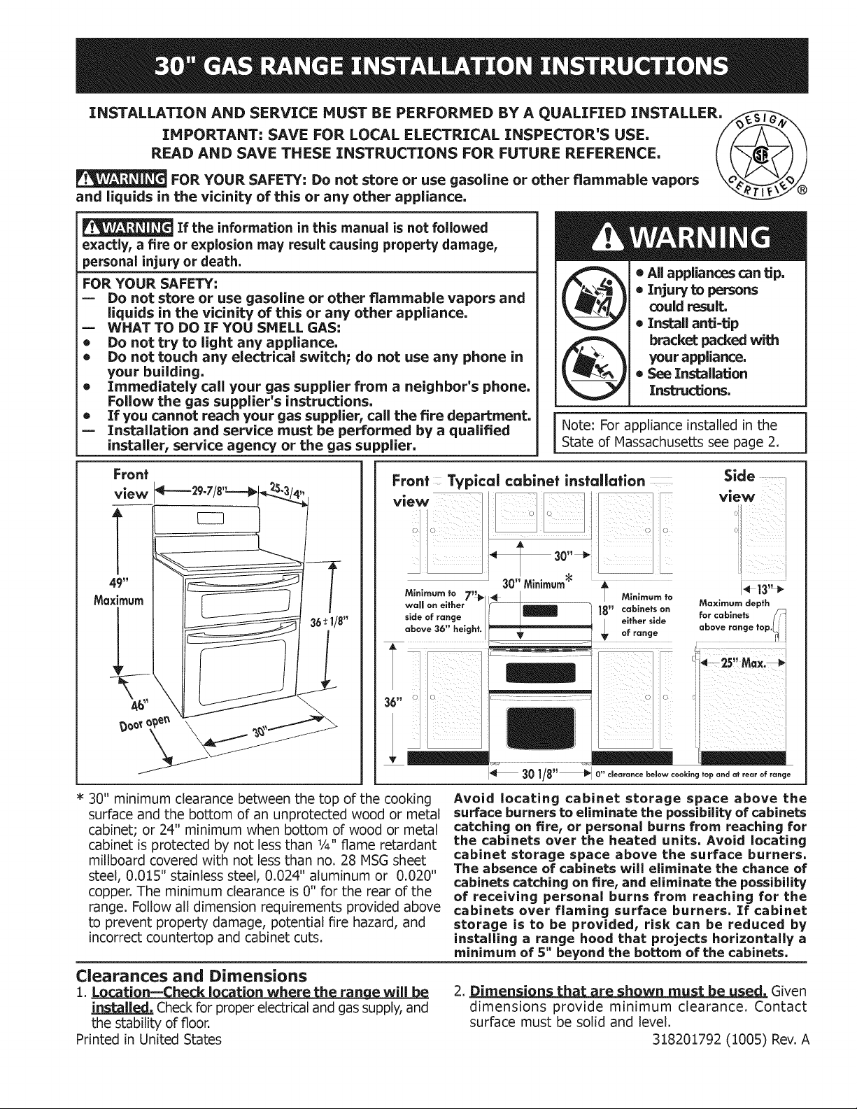
Front
view
Note: For appliance installed in the
State of Massachusetts see page 2.
• All appliances can tip.
• Injury to persons
could result.
®Install anti=tip
bracket p_cked with
your appliance.
• See Installation
Instructions.
49"
Maximum
36-+1/8"
/
A_
* 30" minimum clearance between the top of the cooking
surface and the bottom of an unprotected wood or metal
cabinet; or 24" minimum when bottom of wood or metal
cabinet is protected by not less than 1/4"flame retardant
millboard covered with not less than no. 28 NSG sheet
steel, 0.015" stainless steel, 0.024" aluminum or 0.020"
copper. The minimum clearance is 0" for the rear of the
range. Follow all dimension requirements provided above
to prevent property damage, potential fire hazard, and
incorrect countertop and cabinet cuts.
Clearances and Dimensions
1. Location-- h k l i nwh r h r n will
Checkfor proper electrical and gas supply, and
the stability of floor.
Printed in United States
,\
Avoid locating cabinet storage space above the
surface burners to eliminate the possibility of cabinets
catching on fire, or personal burns from reaching for
the cabinets over the heated units, Avoid locating
cabinet storage space above the surface burners,
The absence of cabinets will eliminate the chance of
cabinets catching on fire, and eliminate the possibility
of receiving personal burns from reaching for the
cabinets over flaming surface burners, If cabinet
storage is to be provided, risk can be reduced by
installing a range hood that projects horizontally a
minimum of 5" beyond the bottom of the cabinets,
2. Dim n i n h r h wnm .Given
dimensions provide minimum clearance. Contact
surface must be solid and level.
318201792 (1005) Rev. A
Page 2
Important Notes to the Installer
1. Read all instructions contained in these installation
instructions before installing the appliance.
2. Remove all packing material before connecting the
electrical supply to the appliance.
3. Observe all governing codes and ordinances.
4. Be sure to leave these instructions with the consumer.
5. Note: For operation at 2000 ft. elevations above sea
level, appliance rating shall be reduced by 4 percent
for each additional 1000 ft.
Important Note to the Consumer
Keep these instructions with your Use and Care Guide
for future reference.
IMPORTANT SAFETY INSTRUCTIONS
Installation of this range must conform with local codes
or, in the absence of local codes, with the National Fuel
Gas Code ANSI Z223,1/NFPA ,54-latest edition,
When installed in a manufactured (mobile) home,
installation must conform with the Manufactured Home
Construction and Safety Standard, Title 24 CFRR, Part
3280 [formerly the Federal Standard for Mobile Home
Construction and Safety, Title 24, HUD (Part 280)] or,
when such standard is not applicable, the Standard
for Manufactured Home Installations, ANSI/NCSBCS
A.225.1, or with local codes.
This range has been design certified by CSA
International. As with any appliance using gas and
generating heat, there are certain safety precautions
you should follow. You will find them in the Use and
Care Guide, read it carefully.
• Be sure your range is installed and grounded
properly by a qualified installer or service
technician.
• This range must be electrically grounded in
accordance with local codes or, in their absence,
with the National Electrical Code ANSI/NFPA No.
70--latest edition. See Grounding Instructions in the
Electrical Requirements section of these Installation
Instructions.
• Before installing the range in an area covered with
linoleum or any other synthetic floor covering, make
sure the floor covering can withstand heat at least 90°F
above room temperature without shrinking, warping or
discoloring. Do not install the range over carpeting unless
you place an insulating pad or sheet of 1/4"(10,16cm)
thick plywood between the range and carpeting.
Hake sure the wall coverings around the range can
withstand the heat generated by the range.
Do not obstruct the flow of combustion air at the oven
vent nor around the base or beneath the lower front
panel of the range. Avoid touching the vent openings
or nearby surfaces as they may become hot while the
oven is in operation. This range requires fresh air for
proper burner combustion.
Air curtains or other overhead range hoods, which
operate by blowing a downward air flow onto a range,
shall not be used in conjunction with gas ranges other
than when the hood and range have been designed,
tested and listed by an independent test laboratory for
use in combination with each other,
Never leave children alone or unattended
in the area where an appliance is in use. As children
grow, teach them the proper, safe use of all appliances.
Never leave the oven door open when the range is
unattended.
Stepping, leaning or sitting on the doors
or drawers of this range can result in serious injuries and
can also cause damage to the range.
Do not store items of interest to children in the cabinets
above the range. Children could be seriously burned
climbing on the range to reach items.
To eliminate the need to reach over the surface burners,
cabinet storage space above the burners should be
avoided.
Adjust surface burner flame size so it does not extend
beyond the edge of the cooking utensil. Excessive flame
is hazardous.
Do not use the oven as a storage space. This creates a
potentially hazardous situation.
Never use your range for warming or heating the room.
Prolonged use of the range without adequate ventilation
can be dangerous.
Do not store or use gasoline or other flammable vapors
and liquids near this or any other appliance. Explosions
or fires could result.
In the event of an electrical power outage, the surface
burners can be lit manually, To light a surface burner,
hold a lit match to the burner head and slowly turn the
Surface Control knob to LITE, Use caution when lighting
surface burners manually,
Reset all controls to the "off" position after using a
programmable timing operation.
Remove broiler pan, food and other utensils before self
cleaning the oven. Wipe up excess spillage. Follow the
precleaning instructions in the Use and Care Guide.
Unlike the standard gas range, THIS COOKTOP IS NOT
REMOVABLE.Do not attempt to remove the cooktop.
Special instructions for aQDliances installed in
h fM h : This Appliance can
only be installed in the state of Nassachusetts by a
Nassachusetts licensed plumber or gas fitter. When
using a flexible connector, it must not exceed three (3)
feet (36 in.) long. A "T" handle type manual gas valve
must be installed in the gas supply line to this appliance.
DO NOT MAKE ANY ATTEMPT
TO OPERATE THE ELECTRIC IGNITION OVEN
DURING AN ELECTRICAL POWER FAILURE. RESET
ALL OVEN CONTROLS TO OFF IN THE EVENT
OF A POWER FAILURE, The electric ignitor will
automatically re-ignite the oven burner when power
resumes if the oven thermostat control was left in the
ON position.
When an electrical power failure occurs during use,
the surface burners will continue to operate.
During a power outage, the surface burners can be
lit with a match. Hold a lighted match to the burner,
then slowly turn the knob to the Lite position. Use
extreme caution when lighting burners this way.
2
Page 3
Before Starting
Tools you will need
For leveling legs and anti-tip brackets:
• Adjustable wrench or channel lock pliers
• 5/16" Nutdriver or Flat Head Screw Driver
• Electric Drill & 1/8 Diameter
Drill Bit (5/32" Masonry Drill
Bit if installing in concrete)
• Level & Measuring Tape
For gas supply connection:
• Pipe Wrench
• Brush
For burner flame adjustment:
• Phillips head and blade-type
screwdrivers
For gas conversion (LP/Propane or Natural):
• Open end wrench - 1/2" ..................:_
Additional materials you will need: j/il
• Gas line shut-off valve _
• Pipejoint sealant that resists action of LP/ _L-L-S_NT_U
Propane gas
• A new flexible metal appliance conduit (V2" NPT x
3/4"or V2" I.D.) must be design certified
by CSAInternational. Because solid pipe
restricts moving the range we recommend
using a new flexible conduit (4 feet length)
for each new installation and additional
reinstallations.
• Always use the (2) new flare union
adapters V2" NPT x 3/4"or V2"I.D.) supplied with the
new flexible appliance conduitfor connectionof the
range.
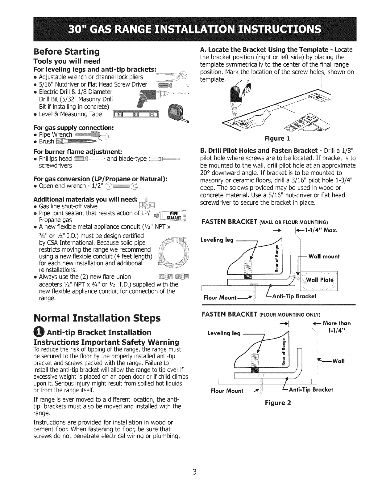
A, Locate the Bracket Using the Template - Locate
the bracket position (right or left side) by placing the
template symmetrically to the center of the final range
position. Mark the location of the screw holes, shown on
template.
Figure 1
B. Drill Pilot Holes and Fasten Bracket - Drill a 1/8"
pilot hole where screws are to be located. If bracket is to
be mounted to the wall, drill pilot hole at an approximate
20° downward angle. If bracket is to be mounted to
masonry or ceramic floors, drill a 3/16" pilot hole 1-3/4"
deep. The screws provided may be used in wood or
concrete material. Use a 5/16" nut-driver or fiat head
screwdriver to secure the bracket in place.
mount
Normal Installation Steps
Anti-tip Bracket Installation
Instructions Important Safety Warning
To reduce the risk of tipping of the range, the range must
be secured to the floor by the properly installed anti-tip
bracket and screws packed with the range. Failureto
install the anti-tip bracket will allow the range to tip over if
excessive weight is placed on an open door or if child climbs
upon it. Serious injury might result from spilled hot liquids
or from the range itselfi
Tfrange is ever moved to a different location, the anti-
tip brackets must also be moved and installed with the
range.
Instructions are provided for installation in wood or
cement floor. When fastening to floor, be sure that
screws do not penetrate electrical wiring or plumbing.
Anti=Tip Bracket
Figure 2
3
Page 4
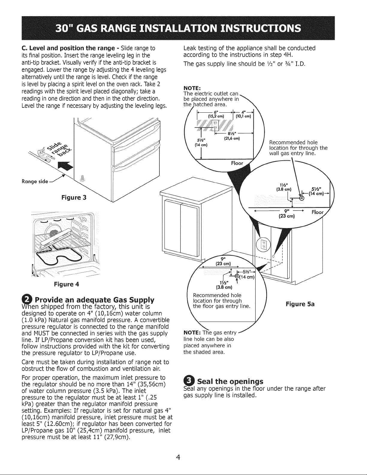
C, Level and position the range = Slide range to
its final position. Insert the range leveling leg in the
anti-tip bracket, Visually verify if the anti-tip bracket is
engaged, Lower the range by adjusting the 4 leveling legs
alternatively until the range is level, Check if the range
is level by placing a spirit level on the oven rack, Take 2
readings with the spirit level placed diagonally; take a
reading in one direction and then in the other direction,
Level the range if necessary by adjusting the leveling legs,
Leak testing of the appliance shall be conducted
according to the instructions in step 4H.
The gas supply line should be 1/2"or ¾" I.D.
NOTE:
The electric outlet can
be placed anywhere
the hatched area.
Range side
Figure 3
_i_---÷_ ¸ , .......
Figure 4
Provide an adequate Gas Supply
en shipped from the factory, this unit is
designed to operate on 4" (10,16cm) water column
(1.0 kPa) Natural gas manifold pressure. A convertible
pressure regulator is connected to the range manifold
and MUST be connected in series with the gas supply
line. If LP/Propane conversion kit has been used,
follow instructions provided with the kit for converting
the pressure regulator to LP/Propane use.
Care must be taken during installation of range not to
obstruct the flow of combustion and ventilation air.
For proper operation, the maximum inlet pressure to
the regulator should be no more than 14" (3S,S6cm)
of water column pressure (3.5 kPa). The inlet
pressure to the regulator must be at least 1" (.25
kPa) greater than the regulator manifold pressure
setting. Examples: If regulator is set for natural gas 4"
(10,16cm) manifold pressure, inlet pressure must be at
least S" (12.60cm); if regulator has been converted for
LP/Propane gas 10" (25,4cm) manifold pressure, inlet
pressure must be at least 11" (27,9cm).
(21,6 crn)
Floor
(23 cm)
(3.8 cm)
Recommended hole
location for through
the floor gas entry line.
NOTE: The gas entry
line hole can be also
placed anywhere in
the shaded area.
SeOalSeal the openings
any openings in the floor under the range after
Recommended hole
location for through the
wall gas entry line.
(23 crn)
Figure Sa
gas supply line is installed.
Floor
4
Page 5

Connect the range to the gas supply
Important: Remove all packing material and literature
from range before connecting gas and electrical supply.
Note: To prevent leaks, put pipe joint sealant on all
external pipe threads.
Do not allow regulator to rotate on
pipe when tightening fittings,
Connection to Pressure Regulator
The regulator is already installed on the appliance.
Do not make the connection too tight,
The regulator is die cast. Overtightening may crack the
regulator resulting in a gas leak and possible fire or
explosion.
Manual
Shutoff Flare
Valve Union
GAS FLOW
Flexible
Connector
1
J Union
: g_ta"e_officeGgii
Unit
Shutoff
Flare
Valve
Unit Pressure
Regulator
!-
/
Figure 5b
A. Install an external manual gas shut-off valve to
gas supply line in an accessible location outside
of the range. Be sure you know where and how to
shut off the gas supply to the range.
B. Install 1/2"flare union adapter to unit shut-off valve
using NO MORE THAN 15ft,/Ibs. of torque.
NOTE: Be sure to stabilize the right side of the
unit shut-off valve with adjustable wrench before
tightening ANY fittings to the unit shut-off valve.
C. Tighten the gas flexible connector and/or
appliance conduit to flare union on the left side
of the unit shut-off valve using NO MORE THAN
15ft./Ibs. of torque. Be sure to stabilize the 1/2"
flare union adapter with an adjustable wrench
before tightening the gas flexible connector and/or
appliance conduit.
D, Install flare union adapter to external shut-off
valve.
E, Attach the gas flexible connector with the flare
union on shut-off valve.
F, Make sure both shut-off valves are in the "ON"
position.
G, Form the gas flexible connector as shown on figure
5c. This will prevent the flexible connector from
pinching or blocking the unit when you will push it
back in its final position.
H. Check for leaks. Turn the gas supply on to the range
and use a liquid leak detector (or soap and water)
at all joints and conduits to check for leaks in the
system.
Do not use a flame to check for gas
leaks,
i
i
i
r--
Figure 5c
Note: The purpose of forming the gas flexible
connector is to position it in a way that will not block
the unit or get pinched in it's final position.
If your unit in place is not against the wall
as you wish, check behind the range and
place the gas flexible connector to avoid
the range being blocked or the gas flexible
connector being pinched,
Checking Manifold Gas Pressure
Disconnect this range and its individual manual shutoff
valve from the gas supply piping system during any
pressure testing of that system at test pressures greater
than 14" water column pressure (approximately 1/2"
psig).
The appliance must be isolated from the gas supply
piping system by closing its individual manual shutoff
valve during any pressure testing of the gas supply
piping system at test pressures equal to or less than
14" water column pressure (approximately 1/2"psig).
[f it should be necessary to check the manifold gas
pressure, connect manometer (water gauge) or
other pressure device to the top burner right rear
orifice. Using a rubber hose with inside diameter of
approximately 1/4"hold tubing down tight over orifice.
Turn burner valve on.
For accurate pressure check have at least two (2)
other top burners burning. Be sure the gas supply
(inlet) pressure is at least one inch above specified
range manifold pressure. The gas supply pressure
should never be over 14" water column. When
properly adjusted for Natural Gas manifold pressure is
4" (For LP/Propane Gas the manifold pressure is 10")
5
Page 6

l_ Electrical Requirements
120 volt, 60 Hertz, properly grounded dedicated circuit
protected by a 15 amp circuit breaker or time delay
fuse.
Note: Not recommended to be installed with a Ground
Assembly of the Burner Caps and
Burner Grates
It is very important to make sure that all of the surface
burner caps and surface burner grates are installed
correctly and in the correct locations.
Fault Interrupt (GFI),
Do not use an extension cord with this range. Burner
Grounding Instructions Ca
IMPORTANT Please read carefully.
For personal safety, this appliance must be
properly grounded.
The power cord of this appliance is equipped with a
3-prong (grounding) plug which mates with a standard
3-prong grounding wall receptacle (see Figure 6) to
minimize the possibility of electric shock hazard from the Fixed
Burner
appliance. Head
The wall receptacle and circuit should be checked by
a qualified electrician to make sure the receptacle is
properly grounded.
Preferred Method
Grounding type
wall rece
Do not, under
circumstances,
cut, remove,
or bypass the
grounding prong.
Electric Ignition Surface Burners
Operation of electric igniters should be checked after
range and supply line connectors have been carefully
checked for leaks, and range has been connected to
Power supply
cord with 3=prong
grounding plug.
Figure 6
electric power. To check for proper lighting:
A. Push in and turn a surface burner knob to the LITE
position. You will hear the igniter sparking.
B. The surface burner should light when gas is
available to the top burner. Each burner should light
Where a standard 2=prong wall receptacle is installed,
it is the personal responsibility and obligation of the
consumer to have it replaced by a properly grounded
3-prong wall receptacle.
Do not, under any circumstances, cut or remove
the third (ground) prong from the power cord.
Disconnect electrical supply cord from
within four (4) seconds after air has been purged
from supply lines. Visually check that burner has lit.
C. Once the burner lights, the control knob should be
rotated out of the LITE position.
D.There are separate ignition devices for each burner.
Try each knob separately until all burner valves have
been checked.
wall receptacle before servicing cooktop.
Gas
Opening
Please note: The
burner heads
are secured to
the cooktop. THE
COOl(TOP IS NOT
REMOVABLE. Do not
attempt to remove or lift
the cooktop.
REMEMBER - DO NOT
ALLOW SPILLS' FOOD'
CLEANING AGENTS OR
ANY OTHER MATERIAL
TO ENTER THE GAS
OPENING OF THE
BURNER. Always keep
the Burner Caps in place
whenever the surface
burners are in use.
6
Page 7

O Adjust the "LOW" Setting of Surface
Burner Valves
Figure 7
A. Push in and turn each control to LITE until burner
ignites.
B. Push in and quickly turn knob to LOWESTPOSITION.
C. If burner goes out, Resetcontrol to OFR
D. Remove the surface burner control knob.
E. Insert a thin-bladed screwdriver into the hollow valve
stem and engage the slotted screw inside. Flame size
can be increased or decreased with the turn of the
screw. Turn counterclockwise to increase flame size.
Turn clockwise to decrease flame size.
Burner Flame Size ----_1 5/8" 4--
Main
Top
Adjust flame until you can quickly turn knob from LITE to
LOWESTPOSITIONwithout extinguishing the flame. Flame
should be as small as possible without going out.
Note; Air mixture adjustment is not required on surface
burners.
Operation of Oven Burners and Oven
Adjustments
Electric Ignition Burners
Operation of electric igniters should be checked after
range and supply line connectors have been carefully
checked for leaks, and range has been connected to
electric power.
The oven burner is equipped with an electric control
system as well as electric oven and broil burner igniters.
These control systems require no adjustment. When the
oven is set to operate, current will flow to the igniter. It will
"glow" similar to a light bulb. When the igniter has reached
a temperature sufficient to ignite gas, the electrically
controlled oven valve will open and flame will appear at the
oven burner. There is a time lapse from 30 to 60 seconds
after thermostat is turned ON before the flame appears
at the oven burner. When the oven reaches the display
setting, the glowing igniter will go off. The burner flame
will go "out" in 20 to 30 seconds after igniter goes "OFF".
To maintain any given oven temperature, this cycle will
continue as long as the display is set to operate.
After removing all packing materials and literature from
the oven:
A. Set the lower oven to BAKE at 300°R See Use & Care
Guide for operating instructions.
B. Within 60 seconds the oven burner should ignite.
Check for proper flame, and allow the burners to
cycle once. Reset controls to OFR
C. Repeat A and B with the upper oven.
D. Set the upper oven to broil. See Use and Care Guide
for operating instructions.
E. Within 60 seconds the broil burner should ignite.
Check for proper flame. Reset controls to off.
7
Page 8

Air Shutter=Broil Burner
The approximate flame length from the burner is 1 inch
(distinct inner cone of blue flame).
To determine if the broil burner flame is proper, set the
oven to broil.
If flame is yellow in color, increase air shutter opening
size (see "2" in Figure 8 ). If the entire flame is blue,
reduce the air shutter opening size.
To adjust, loosen lock screw (see "3" in Figure 8),
reposition air shutter, and tighten lock screw.
o
Care, Cleaning and Haintenance
Refer to the Use & Care Guide for cleaning
instructions.
If moving the range is necessary for cleaning or
maintenance, shut off gas supply. Disconnect the
gas and electrical supply. If gas or electrical supply is
inaccessible, lift the unit slightly at the front and pull
out away from the wall.
Pull only as far as necessary to disconnect the gas and
electrical supply. Finish moving the unit for servicing
and cleaning. Reinstall in reverse order making sure to
level the range and check gas connections for leaks.
Before You Call for Service
Read the Before You Call for Service Checklist and
operating instructions in your Use and (::are Guide.
It may save you time and expense. The list includes
common occurrences that are not the result of
defective workmanship or materials in this appliance.
Figure 8
Hake sure range is level
Level the range by placing a level horizontally on an
oven rack. Check diagonally from front to back, then
level the range by adjusting the leveling legs.
After installation is completed, make
sure all controls are left in the OFF
position,
LP/Propane Gas Conversion
This appliance can be used with Natural gas or LP/
Propane gas. It is shipped from the factory for use
with natural gas.
If you wish to convert your range for use with LP/
Propane gas, use the supplied fixed orifices located
in a bag containing the literature marked "FOR LP/
PROPANE GAS CONVERSION." Follow the instructions
packaged with the orifices for surface, oven and broil
burners conversion.
The conversion must be performed by a qualified
service technician in accordance with the
manufacturer's instructions and all local codes and
requirements. Failure to follow these instructions
could result in serious injury or property damage.
The qualified agency performing this work assumes
responsibility for the conversion.
Failure to make the appropriate
conversion can result in serious personal injury and
property damage.
Serial Plate Information
The serial plate
is located on the
decorative bottom
trim and it is
visible when the
lower oven door is
opened.
8
Page 9

Notes
9
Page 10

Notes
10
Page 11

[] OVEN CIRCUIT // CIRCUITO DE HORNO i
W-6 [] iG,+GRBEN/VERDE
Iilllllllllllllllllllllllllllllllllllllllllllllllllllllllllillllll P2 =GRD iBK.*BLACK/NEGRO
UPR OV . J3 ....................... =V LED iV.-VIOLET/VIOLETA
W-14 .....................................1 J2 =v UR iT,-TAN/CAFE CLARO
LATCH N_OTOR/MOT(_R_ DE DERROJO 4
_ ./ BR-14
.....,........ [ A
W 14 /:;_:'_ / 7
I IIIIIIIIIIIIIIIIIIIIIIIIIIIIIIIIIIIIIIIIIIIIIIIIIIIIIIII I _I4IIII
W 14 LWR OV "
i BOrO.VFB_][A[_ORD_COMV£CC_O": 2
COBVEC_ZO_ MofCfi #AN7 q
;BR/,,/-,4 _7_BR/W-,4 i R-14
EOO RELAY BOARD/ R 6 iw''wHZTE/BLANCO
PANEL DE RELEVADORES PANEL [NDICADOR DEL HORNO i O'"ORANGE/NARANJA
DEL HORNO iY.-YELLOW/AMAR[LLO
IIIIIIIIIIIIIIIIIIIIIIIIIIIIIIIIIIIIIIL _1111111111111_ iBR,-BROWN/CAFE
2 =ZERO CROSS BLANCO
R_14
3
J5
J7 ;
= BK 22 - iBL.-BLUE/AZUL
=
" W-22
............=r..............."
I
= R22
EOC*OISPLAY BOARD/ i R'-RED/ROJO
- BR/W. BROWN SIRIPES/WHIrE // CARE RAYAS
Y-22 : d3
: UPR MDL
= UPR BR EL_
J5
_LWR BA ELM
:IWR CON ElM
_LWR CON FN
: LWR MDL
: OV LT
OV LT
UPR BA ELM
WGL STMLS
• 'Kj ....
/ _ ! GY-14 5
L,_'JL,,_A,A 6
W-14 _b i BR-14
fr,, ..............
BAKE VALVE/
VALVULA DE MORNRAR
OPTZON 8
OPCION 9
iiiiilillllllllllllllllllllllll
I
d6 : "
:
5
:
iiiiiiiiiiiii"IiiiiiiiiiIIII_IIIIIIIIIIIIII"IIIII
" = P8 =
" UPR OV
= i=
m
: PWM REL
i=
i=
i'BK-14 BK-2O _ BK-20 BK_14
[]- ......4>
isY._REY/ORIS
LEGEND/LEYENDA
TRM.-THERMAL CIRCUIT BREAKER/INTERRUPTORi
TERMICO
UPR OV. UPPER OVEN/HORNO SUPERIOR
iLWR OV.-LOWER OVEN /HORNO INFERIOR
CODE GAUGE TE_,P "0 OSA lJ/
CODE CALIBRE
1 _8 125 0L1251 3t73
i6 125 CIt251 3173
14 125 0L1251 3173
4 12 125 OLI251 3173
5 i8 150 EXL150 3321
6 t6 150 EXL 150 3821
7 14 i50 EXI 150 3321
8 _2 150 EXL:150 3321
£ t0 150 EX[150 3321
10 t8 200 SEW-1 3122
tl 16 200 SEW-1 3122
12 12 250 3252
t3 t6 250 3252
t4 20 150 EXL 150 3321
t5 8 !50 EXL 150 3321
t6 8 60
t7 to 60
t8 10 200 SEW:I 3122
t£ 20 125 0L1251 3173
20 20 200 SEW 1 3t22
21 22 125 0L-1251 3t73
22 22 150 EXI 150 3321
23 t8 200 35Z3
24 2O 460 5107
Z5 iS 450 5107
34 16 200 3512
LATCH MOTOR/
MOTOR DE CERROJO
No c
i)ooR SWI]OH/
INTERRURTOBRE PMERTA
5335
BK 14
BAKE VALVE/ =
VALVULA BE MORNEAR
_,-_1 ENMENDIDO DE NORNEAR :
_j Y 14
CONVECT][ON ELEMENTI
0 5 ELEMENTO DE CONVECCION 0 5 _ "
;; i: ............... <'_ .............. : : CONV
7 " =
BAKE EGNETER/
,_ _ - •
i OPTION
i OPCION
CAUTION:DISCONNECT POWER BEFORE SERVICING UNIT.
LABEL ALL WIRES PRIOR TO DISCONNECTION WHEN SERVICING CONTROLS.
WIRINGS ERRORS CAN CAUSE IMPROPER AND DANGEROUS OPERATION.
VERIFY PROPER OPERATION AFTER SERVICING.
ATENCtON:CORTAR LA CORRIENTE ANTES DE REALIZAR EL MANTENIMIENTO DEL ELECTRODOMESTICO.
ETIQUETE TODOS LOS CABLES ANTES DE DESCONECTAR CUANDO HAGA EL SERVICIO A LOS CONTROLES.
ERRORES AL VOLVER A ENSAMBLAR LOS CABLES PUEDE CAUSAR FALLAS U OPERACIONES PELIGROSAS.
VERIFIQUE LA CORRECTA OPERACION DESPUES DEL SERVICIO.
IIIIIlllllllllllllllllllllllll
;,,,,,,,,,,,,,,,,,,,,,,,,,,,,,,,,,,,,,; :
IIIIIIIIIIIII1_111111111111_111111111111 IIIIII
_LWROV : __> _] TEMPERATURE PROBE/
11
jiB<-'4
P6 -
: _BK-I4 \ \ [W_ TEMPERATURE PROBE/
_/= / / SONDA DE TEMPERATURA
oPROV
:BK-14 \ \ LWR OV
PIO = LATCH MOTOR/
] "BK- 14 -- BK-14
MOTOR DE BERROJO
[]
[]
;,,,,,,,,,,,,,;
SONOA BE TEMPERAIURA
Page 12

COOKTOP CIRCUIT // CIRCUITO DE PLANCHA DE COCINAR
TOP BURNER _GNTTER
QUEMAOOR DE ENCENNIGO SUPERIOR
j--.
w4°/
TOP BURNER IGNITER
QUEMADOR DE ENCENDIDO SUPERIOR
w4oI_ ;
TOP BURNER IGNITER !
QUEMADOR DE ENCENDIDO SURER[OR I
w- o ; OPTION
TOP BURNER IGNITER
QUEMADOR DE ENDENDIDO SUPERIOR
TOP BURNER IGNITER
OUE_ADOR BE ENCENDIDO SUPERIOR
IGNITER MODULE BOARD
CUADBO DE MODULO DE ENCENDIDO
OPClON
rl_ F
R-14_
1 i
1 /. F
r*', r
R-14_
W-14 \
120VAC /ABUT
A2 4
JlJ._ TRANSFORMER/
A1 f_Y'A3 TRANSFORMADOR
t20VAC
IN
N L
INTERRUPTOB ENCENDIDO
IGNITER SWITCH
R 14
INTERRUPTOR ENCENDIDO
IGNITER SWITCH
1
R-14 OPIION
IGNITER SWITCH i
INTERRUPTOR ENOENDIDO I
' OPOION
R t4
INTERRURTOR ENCENDIDO
IGNIIER SWIgCH
R-14
INTERRUPTOR ENOENDIDO
IGNI1ER SWITCH
R_14
CONNECTOR
CONEOTOR
A
CAUTION:DISCONNECT POWER BEFORE SERVICING UNIT.
LABEL ALL WIRES PRIOR TO DISCONNECTION WHEN SERVICING CONTROLS,
WIRINGS ERRORS CAN CAUSE IMPROPER AND DANGEROUS OPERATION,
VERIFY PROPER OPERATION AFTER SERVICING.
ATENCION:CORTAR LA CORRIENTE ANTES DE REALIZAR EL MANTENIMIENTO DEL ELECTRODOMESTICO.
ET[QUETE TODOS LOS CABLES ANTES DE BESCONECTAR CUANO0 HAGA EL SERV[CIO A LOS CONTROLES.
ERRORES AL VOLVER A ENSAMBLAR LOS CABLES PUEDE CAUSAR FALLAS U OPERAC[ONES PEL[GROSAS,
VERIFIQUE LA CORRECTA OPERACION DESPUES DEL SERVICIO,
12
CODE GAUGE TEMP.'C CSA UL
CODIGO MEDIDA
1 16 12S 011251 3173
2 16 t25 0LI251 3173
3 14 125 CL1251 3173
4 12 125 CL1251 3173
5 18 150 EXL-150 3321
6 16 t50 EXL-150 3321
7 14 150 EXL_150 3321
8 12 150 EXL 150 3321
9 10 150 EXL 150 3321
10 18 200 SEW+I 3122
11 16 200 S_l-1 3122
12 12 250 3252
13 16 250 3252
14 20 150 EX[_150 3321
15 8 t50 EXI-150 3321
16 8 60
17 10 60
18 10 200 SEW-1 3122
19 20 125 0L1251 3173
20 20 200 SEVI*I 3122
21 22 125 3266
22 22 150 10109
23 18 200 3573
34 16 200 3512
35 18 200 3512
37 14 20O 3512
40 18 200 3204 OR/OU 10202
4t 20 200 3512
 Loading...