

Page 1
INSTALLATIONAND SERVICE MUST BE PERFORMED BY A QUALIFIED INSTALLER.
IMPORTANT: SAVE FOR LOCAL ELECTRICAL INSPECTOR'S USE.
READ AND SAVE THESE INSTRUCTIONS FOR FUTURE REFERENCE.
pr_ If the information in this manual is not followed
exactly, a fire or explosion may result causing property
damage, personal injury or death.
FOR YOUR SAFETY:
-- Do not store or use gasoline or other flammable vapors
and liquids in the vicinity of this or any other appliance.
-- WHAT TO DO IF YOU SMELL GAS:
• Do not try to light any appliance.
• Do not touch any electrical switch; do not use any phone
in your building.
• Immediately call your gas supplier from a neighbor's
phone. Follow the gas supplier's instructions.
• If you cannot reach your gas supplier, call the fire
department.
-- Installation and service must be performed by a qualified
installer, service agency or the gas supplier.
ALL RANGES
CAN TIP.
INJURY TO
PERSONS
COULD
RESULT.
INSTALL
ANTI-TIP
DEVICE
PACKED WITH
RANGE.
SEE
INSTALLATION
INSTRUCTIONS.
297/8
2 53/8"
t
Optional
Spice
Rack
with 1
48 1/2"
47-3/4"
Maximum"
44 3/8" \
Door Open \\
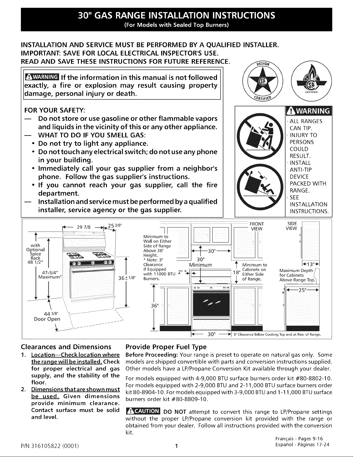
Clearances and Dimensions
1. Location--Check location where
the range will be installed. Check
for proper electrical and gas
supply, and the stability of the
floor.
2. Dimensions that are shown must
be used. Given dimensions
provide minimum clearance.
Contact surface must be solid
and level.
P/N 316105822 (0001)
VIEW
Side of Range I I
Above 36" I_--- B O" -------_
SIDE
*"e4go_t;s,,I 3;"
Clearance Minimum
if Equipped 2"
with 11000 BTU
Burners.
30" Clearance Below Cooking Top and at Rear of Range.
t Minimum to
18" Cabinetson
Either Side
of Range.
Maximum Depth
for Cabinets
Above Range
Provide Proper Fuel Type
Before Proceeding: Your range is preset to operate on natural gas only. Some
models are shipped convertible with parts and conversion instructions supplied.
Other models have a LP/Propane Conversion Kit available through your dealer.
For models equipped with 4-9,000 BTU surface burners order kit #80-8802-10.
For models equipped with 2-9,000 BTU and 2-11,000 BTU surface burners order
kit 80-8904-10. For models equipped with 3-9,000 BTU and 1-11,000 BTU surface
burners order kit #80-8809-10.
DO NOT attempt to convert this range to LP/Propane settings
without the proper LP/Propane conversion kit provided with the range or
obtained from your dealer. Follow all instructions provided with the conversion
kit.
Fran(_ais- Pages 9-16
1 Espafiol- P_ginas 17-24
1÷13"÷1
Page 2
Important Notes to the Installer
1. Read all instructions contained in these installation
instructions before installing range.
2. Remove all packing material from the oven
compartments before connecting the gas and electrical
supply to the range.
3. Observe all governing codes and ordinances.
4. Be sure to leave these instructions with the consumer.
Important Note to the Consumer
1. Keep these instructions with your owner's guide for
future reference.
IMPORTANT SAFETY
INSTRUCTIONS
Installation of this range must conform with local codes or,
in the absence of local codes, with the National Fuel Gas
Code ANSI Z223.1--1atest edition when installed in the
United States. When installed in Canada, installation must
conform with CAN/CGA-B149.1 and CAN/CGA-B149.2.
This range has been design certified by CSA International.
As with any appliance using gas and generating heat, there
are certain safety precautions you should follow. You will
find them in the Owner's Guide., read it carefully.
• Be sure your range is installed and grounded properly
by a qualified installer or service technician.
• This range must be electrically grounded in
accordance with local codes or, in their absence,
with the National Electrical Code ANSl/NFPA
No .70--latest edition when installed in the United
States. When installed in Canada, this range must be
electrically grounded in accordance with CSA Standard
C22.1, Canadian Electrical Code, Part 1. See Grounding
Instructions on page 5.
• Before installing the range in an area covered with
linoleum or any other synthetic floor covering,
make sure the floor covering can withstand heat at
least 90°F above room temperature without
shrinking, warping or discoloring. Do not install the
range over carpeting unless you place an insulating
pad or sheet of 1/4-inch thick plywood between the
range and carpeting.
• Make sure the wall coverings around the range can
withstand the heat generated by the range.
• Do not obstruct the flow of combustion air at the
oven vent nor around the base or beneath the lower
front panel of the range. Avoid touching the vent
openings or nearby surfaces as they may become hot
while the oven is in operation. This range requires fresh
air for proper burner combustion.
Never leave children alone or unattended
in the area where an appliance is in use. As children
grow, teach them the proper, safe use of all appliances.
Never leave the oven door open when the range is
unattended.
Stepping, leaning or sitting on the doors
or drawers of this range can result in serious injuries
and can also cause damage to the range.
• Do not store items of interest to children in the
cabinets above the range. Children could be seriously
burned climbing on the range to reach items.
• To eliminate the need to reach over the surface
burners, cabinet storage space above the burners
should be avoided.
• Adjust surface burner flame size so it does not
extend beyond the edge of the cooking utensil.
Excessive flame is hazardous.
• Do not use the oven as a storage space. This creates
a potentially hazardous situation.
• Never use your range for warming or heating the
room. Prolonged use of the range without adequate
ventilation can be dangerous.
• Do not store or use gasoline or other flammable
vapors and liquids near this or any other appliance.
Explosions or fires could result.
• Reset all controls to the "off" position after using a
programmable timing operation.
FOR MODELS WITH SELF-CLEAN FEATURE:
• Remove broiler pan, food and other utensils before
self-cleaning the oven. Wipe up excess spillage. Follow
the precleaning instructions in the Owner's Guide.
• Unlike the standard gas range, THIS COOKTOP IS
NOT REMOVABLE. Do not attempt to remove the
cooktop.
DO NOT MAKE ANYATTEMPTTO OPERATE
THE ELECTRIC IGNITION OVEN DURING AN ELECTRICAL
POWER FAILURE. RESET ALL OVEN CONTROLS TO "OFF"
IN THE EVENT OF A POWER FAILURE.
The electric ignitor will automatically re-ignite the oven
burner when power resumes if the oven thermostat
control was left in the "ON" position.
When an electrical power failure occurs during use, the
surface burners will continue to operate.
During a power outage, the surface burners can be lit with
a match. Hold a lighted match to the burner, then slowly
turn the knob to the LITE position. Use extreme caution
when lighting burners this way.
Page 3
Before Starting
Tools You Will Need
For leveling legs and Anti-Tip Bracket:
• Adjustable wrench or channel lock pliers
• 5/16" Nutdriver or Flat Head Screw Driver (__
• Electric Drill & 1/8" Diameter Drill Bit (5/32" Masonry
Drill Bit if installing in concrete)
For gas supply connection:
• Pipe wrench
For burner flame adjustment:
• Phillips head and
blade-type screwdrivers
For gas conversion (LP/Propane or Natural):
• Open end wrench - 1/2"
Additional Materials You Will Need
• Gas line shut-off valve i._,_:
• Pipe joint sealant that resists action of LP/Propane gas
A new flexible metal appliance conduit (1/2" NPT x 3/
4" or 1/2" I.D.) must be design certified by CSA
International. Because solid pipe restricts moving the
range we recommend using a new flexible conduit (4
to 5foot length) for each new installation and additional
reinstallations.
_1
A. Locate the Bracket Using the Template- (Bracket may
be located on either the left or right side of the range.
Use the information below to locate the bracket if
template is not available). Mark the floor or wall where
left or right side of the range will be located. If rear of
range is against the wall or no further than 1-1/4" from
wall when installed, you may use the wall or floor
mount method. If molding is installed and does not
allow the bracket to fit flush against the wall, remove
molding or mount bracket to the floor. For wall mount,
locate the bracket by placing the back edge of the
template against the rear wall and the side edge of
template on the mark made referencing the side of the
range. Place bracket on top of template and mark
location of the screw holes in wall. If rear of range is
further than 1-1/4" from the wall when installed, attach
bracket to the floor. For floor mount, locate the
bracket by placing back edge of the template where
the rear of the range will be located. Markthe location
of the screw holes, shown in template.
- .......
/
..........
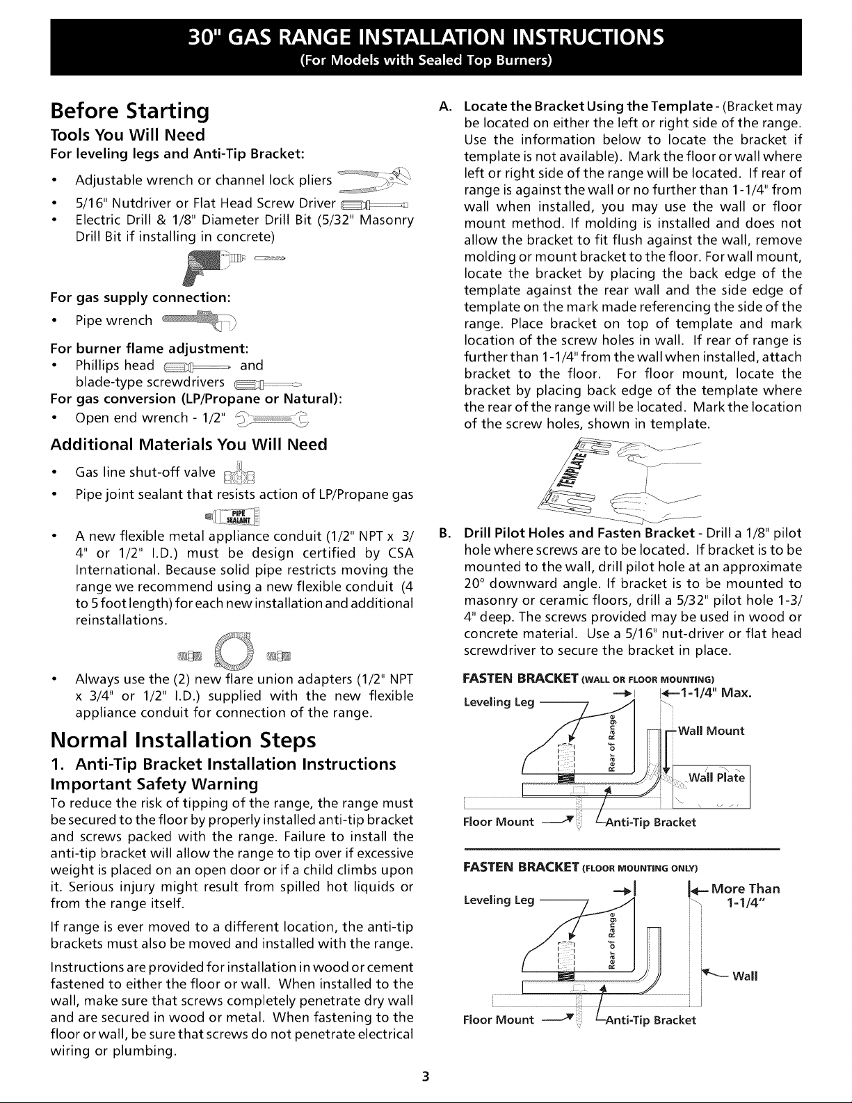
B. Drill Pilot Holes and Fasten Bracket - Drill a 1/8" pilot
hole where screws are to be located. If bracket is to be
mounted to the wall, drill pilot hole at an approximate
20 ° downward angle. If bracket is to be mounted to
masonry or ceramic floors, drill a 5/32" pilot hole 1-3/
4" deep. The screws provided may be used in wood or
concrete material. Use a 5/16" nut-driver or flat head
screwdriver to secure the bracket in place.
• Always use the (2) new flare union adapters (1/2" NPT
x 3/4" or 1/2" I.D.) supplied with the new flexible
appliance conduit for connection of the range.
Normal Installation Steps
1. Anti-Tip Bracket Installation Instructions
Important Safety Warning
To reduce the risk of tipping of the range, the range must
be secured to the floor by properly installed anti-tip bracket
and screws packed with the range. Failure to install the
anti-tip bracket will allow the range to tip over if excessive
weight is placed on an open door or if a child climbs upon
it. Serious injury might result from spilled hot liquids or
from the range itself.
If range is ever moved to a different location, the anti-tip
brackets must also be moved and installed with the range.
Instructions are provided for installation in wood or cement
fastened to either the floor or wall. When installed to the
wall, make sure that screws completely penetrate dry wall
and are secured in wood or metal. When fastening to the
floor or wall, be sure that screws do not penetrate electrical
wiring or plumbing.
\
p Bracket
FASTEN BRACKET (FLOOR MOUNTING ONLY)
Leveling Leg --
iiiiil
Floor Mount p Bracket
Mount
Wall Plate
I_e- More Than
1=1/4"
_k Wall
Page 4

C.
Level and Position Range - Level range by adjusting
the (4) leveling legs with a wrench. Note: A minimum
clearance of 1/8" is required between the bottom of the
range and the leveling leg to allow room for the
bracket. Use a spirit level to check your adjustments.
Slide range back into position. Visually checkthat rear
leveling leg is inserted into and fully secured by the
Anti-Tip Bracket by removing lower panel or storage
drawer. For models with a warmer drawer or broiler
compartment, grasp the top rear edge of the range and
carefully attempt to tilt it forward.
(17turn)
[
for
120V Outlet on Rear of
Wall and Area for Thru
the Wall Connection of
Pipe Stub and Shut Off
Valve is Shaded Area.
9.11
Range Side
2. Provide an adequate gas supply.
This unit is pre-set to operate on 4" natural gas manifold
pressure. A convertible pressure regulator is connected to
the manifold and MUST be connected in series with the gas
supply line. If the LP/Propane conversion kit has been used,
follow instructions provided with the kit for converting the
pressure regulator to LP/Propane use.
Care must be taken during installation of range not to
obstruct the flow of combustion and ventilation air.
For proper operation, the maximum inlet pressure to the
regulator should be no more than 14 inches of water
column pressure. The inlet pressure to the regulator must
be at least 1 inch greater than regulator manifold pressure.
Examples: If regulator is set for natural gas 4 inch manifold
pressure, inlet pressure must be at least 5 inches; if regulator
has been converted for LP/Propane gas 10 inch manifold
pressure, inlet pressure must be at least 11 inches.
Leak testing of the appliance shall be conducted according
to the instructions in step 4g.
Recommended Area for Thru
the Floor Connection of
Pipe Stub and Shut Off Valve.
I " - - 41_-- Wall
Edge
3. Seal the openings.
Seal any openings in the wall behind the range and in the
floor under the range after gas supply line is installed.
4. Connect the range to the gas supply.
To prevent leaks, put a pipe joint sealant on all male
(outside) pipe threads.
Your regulator is in the location shown below.
Do not allow regulator to turn on pipe
when tightening fittings.
Front Access
to Regulator:
Remove Kick Panel,
StorageDrawer, or
Warmer Drawer.
(See Owner's Guide
for Instructions).
If Equipped with
Broiler Drawer,
Broiler Drawer.
Pressure
Regulator
location at
rear of
The gas supply line should be 1/2" or 3/4" I.D.
4
Page 5
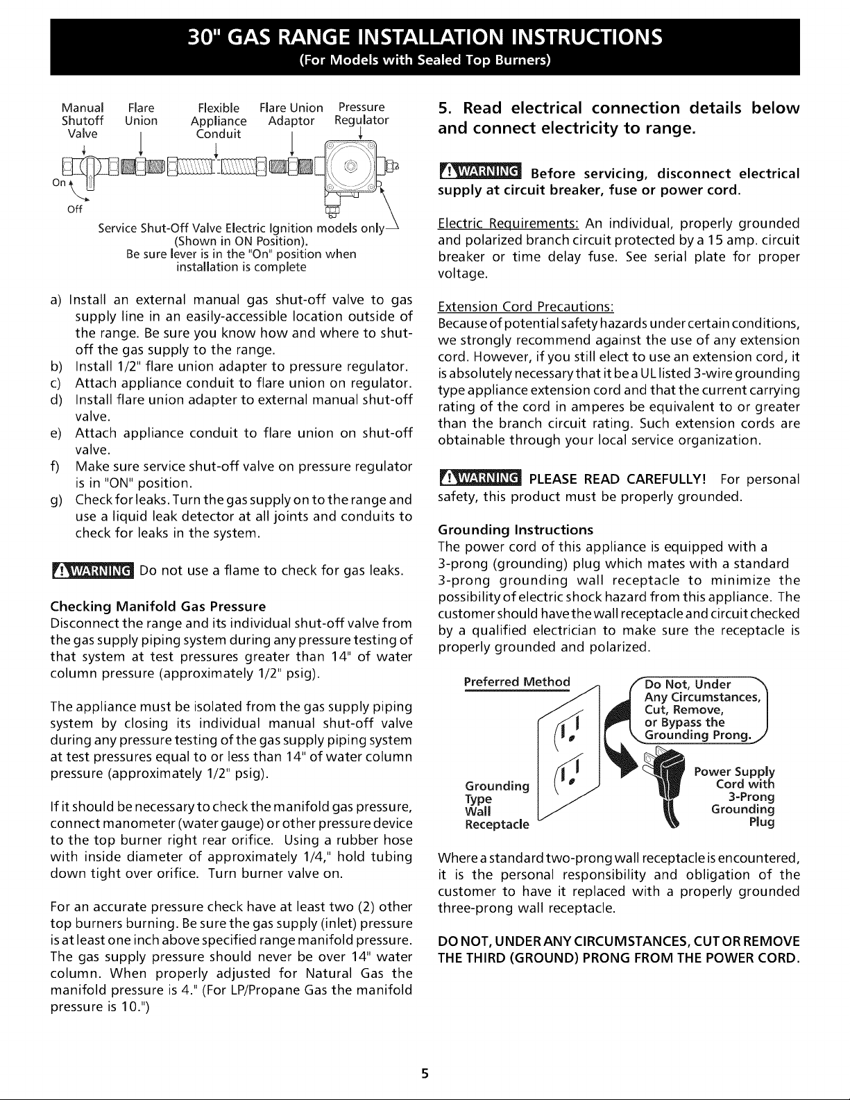
Manual Flare Flexible Flare Union Pressure
Shutoff Union Appliance Adaptor Regulator
Valve / Conduit /
off
Service Shut-Off Valve Electric Ignition models only _
(Shown in ON Position).
Be sure lever is in the "On" position when
installation is complete
5. Read electrical connection details below
and connect electricity to range.
Before servicing, disconnect electrical
supply at circuit breaker, fuse or power cord.
Electric Requirements: An individual, properly grounded
and polarized branch circuit protected by a 15 amp. circuit
breaker or time delay fuse. See serial plate for proper
voltage.
a) Install an external manual gas shut-off valve to gas
supply line in an easily-accessible location outside of
the range. Be sure you know how and where to shut-
off the gas supply to the range.
b) Install 1/2" flare union adapter to pressure regulator.
c) Attach appliance conduit to flare union on regulator.
d) Install flare union adapter to external manual shut-off
valve.
e) Attach appliance conduit to flare union on shut-off
valve.
f) Make sure service shut-off valve on pressure regulator
is in "ON" position.
g) Check for leaks. Turn the gas supply on to the range and
use a liquid leak detector at all joints and conduits to
check for leaks in the system.
Do not use a flame to check for gas leaks.
Checking Manifold Gas Pressure
Disconnect the range and its individual shut-off valve from
the gas supply piping system during any pressure testing of
that system at test pressures greater than 14" of water
column pressure (approximately 1/2" psig).
The appliance must be isolated from the gas supply piping
system by closing its individual manual shut-off valve
during any pressure testing of the gas supply piping system
at test pressures equal to or less than 14" of water column
pressure (approximately 1/2" psig).
If it should be necessaryto checkthe manifold gas pressure,
connect manometer (water gauge) or other pressure device
to the top burner right rear orifice. Using a rubber hose
with inside diameter of approximately 1/4," hold tubing
down tight over orifice. Turn burner valve on.
For an accurate pressure check have at least two (2) other
top burners burning. Be sure the gas supply (inlet) pressure
is at least one inch above specified range manifold pressure.
The gas supply pressure should never be over 14" water
column. When properly adjusted for Natural Gas the
manifold pressure is 4." (For LP/Propane Gas the manifold
pressure is 10.")
Extension Cord Precautions:
Because of potential safety hazards under certain conditions,
we strongly recommend against the use of any extension
cord. However, if you still elect to use an extension cord, it
isabsolutely necessarythat it be a UL listed 3-wire grounding
type appliance extension cord and that the current carrying
rating of the cord in amperes be equivalent to or greater
than the branch circuit rating. Such extension cords are
obtainable through your local service organization.
PLEASE READ CAREFULLY! For personal
safety, this product must be properly grounded.
Grounding Instructions
The power cord of this appliance is equipped with a
3-prong (grounding) plug which mates with a standard
3-prong grounding wall receptacle to minimize the
possibilityof electric shock hazard from this appliance. The
customer should have the wall receptacle and circuit checked
by a qualified electrician to make sure the receptacle is
properly grounded and polarized.
Preferred
Grounding
Type
Wall
Receptacle
Where a standard two-prong wall receptacle is encountered,
it is the personal responsibility and obligation of the
customer to have it replaced with a properly grounded
three-prong wall receptacle.
Not, Under
Any Circumstances, I
Cut, Remove, |
or Bypass the J
Grounding Prong.,/'
Power Supply
Cord with
3-Prong
Grounding
Plug
DO NOT, UNDER ANY CIRCUMSTANCES, CUT ORREMOVE
THE THIRD (GROUND) PRONG FROM THE POWER CORD.
Page 6
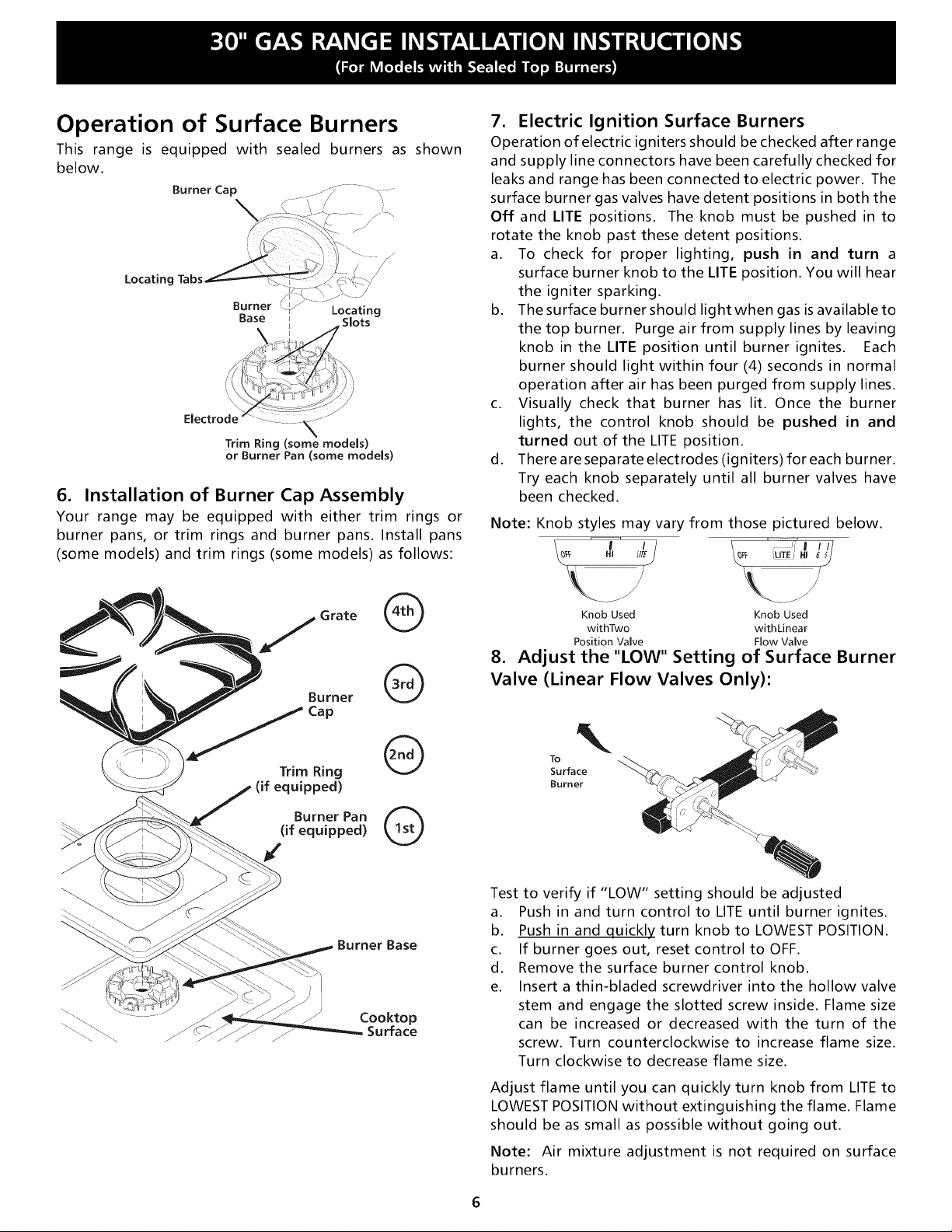
Operation of Surface Burners
This range is equipped with sealed burners as shown
below.
Burner Cap
Locating Tabs
Trim Ring (some models)
or Burner Pan (some models)
6. Installation of Burner Cap Assembly
Your range may be equipped with either trim rings or
burner pans, or trim rings and burner pans. Install pans
(some models) and trim rings (some models) as follows:
7. Electric Ignition Surface Burners
Operation of electric igniters should be checked after range
and supply line connectors have been carefully checked for
leaks and range has been connected to electric power. The
surface burner gas valves have detent positions in both the
Off and LITE positions. The knob must be pushed in to
rotate the knob past these detent positions.
a. To check for proper lighting, push in and turn a
surface burner knob to the LITE position. You will hear
the igniter sparking.
b. The surface burner should light when gas is available to
the top burner. Purge air from supply lines by leaving
knob in the LITE position until burner ignites. Each
burner should light within four (4) seconds in normal
operation after air has been purged from supply lines.
c. Visually check that burner has lit. Once the burner
lights, the control knob should be pushed in and
turned out of the LITE position.
d. There are separate electrodes (igniters) for each burner.
Try each knob separately until all burner valves have
been checked.
Note: Knob styles may vary from those pictured below.
Burner
J Cap
Trim Ring
Burner Pan
(if equipped)
€,
Grate @
_ed)
Burner Base
Cooktop
Surface
@
@
®
Knob Used KnobUsed
withTwo withkinear
PositionValve FlowValve
8. Adjust the "LOW" Setting of Surface Burner
Valve (Linear Flow Valves Only)"
TO
Surface
Burner k_
Test
to verify if "LOW" setting should be adjusted
a.
Push in and turn control to kITE until burner ignites.
b.
Push in and quickly turn knob to LOWEST POSMON.
C.
If burner goes out, reset control to OFF.
d.
Remove the surface burner control knob.
e.
Insert a thin-bladed screwdriver into the hollow valve
stem and engage the slotted screw inside. Flame size
can be increased or decreased with the turn of the
screw. Turn counterclockwise to increase flame size.
Turn clockwise to decrease flame size.
Adjust flame until you can quickly turn knob from LITE to
LOWEST POSITION without extinguishing the flame. Flame
should be as small as possible without going out.
Note: Air mixture adjustment is not required on surface
burners.
Page 7
Operation of Oven Burners and
Oven Adjustments
9. Electric Ignition Burners
Operation of electric igniters should be checked after range
and supply line connectors have been carefully checked for
leaks and range has been connected to electric power.
The oven burner is equipped with an electric control system
as well as an electric oven burner igniter. If your model is
equipped with a waist-high broil burner, it will also have an
electric burner igniter. These control systems require no
adjustment. When the oven is set to operate, current will
flow to the igniter. It will "glow" similar to a light bulb.
When the igniter has reached a temperature sufficient to
ignite gas, the electrically controlled oven valve will open
and flame will appear at the oven burner. There is a time
lapse from 30 to 60 seconds after the thermostat is turned
ON before the flame appears at the oven burner. When the
oven reaches the dial setting, the glowing igniter will go
off. The burner flame will go "out" in 20 to 30 seconds after
the igniter goes "OFF." To maintain any given oven
temperature, this cycle will continue as long as the dial (or
display) is set to operate.
The approximate flame length of the oven burner is 1 inch
(distinct inner, blue flame).
To determine ifthe oven burner flame is proper, remove the
oven bottom and burner baffle and set the oven to bake at
300°F.
To remove the oven bottom, remove oven hold down
screws at rear of oven bottom. Pull up at rear, disengage
front of oven bottom from oven front frame, and pull the
oven bottom out of the oven. Remove burner baffle so that
the burner flame can be observed.
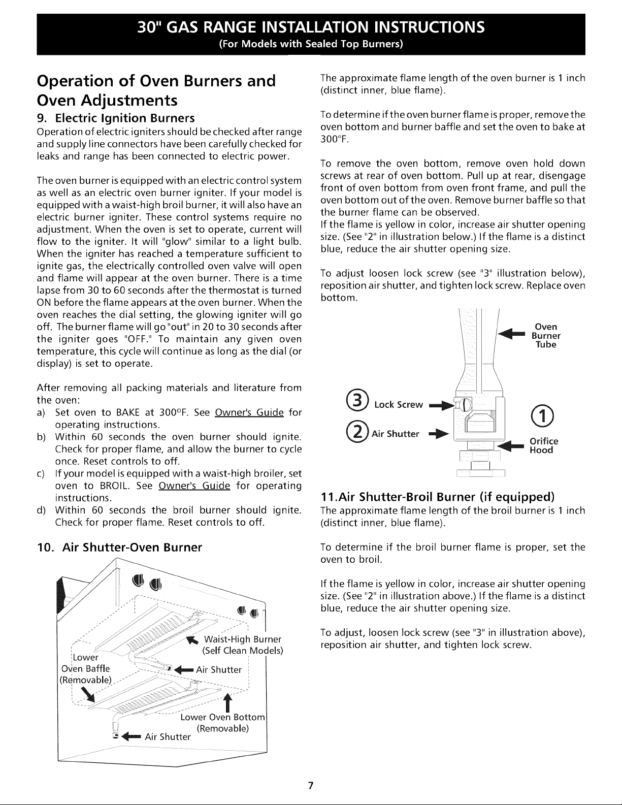
If the flame is yellow in color, increase air shutter opening
size. (See "2" in illustration below.) If the flame is a distinct
blue, reduce the air shutter opening size.
To adjust loosen lock screw (see "3" illustration below),
reposition air shutter, and tighten lock screw. Replace oven
bottom.
Oven
'_ Burner
Tube
After removing all packing materials and literature from
the oven:
a) Set oven to BAKE at 300°F. See Owner's Guide for
operating instructions.
b) Within 60 seconds the oven burner should ignite.
Check for proper flame, and allow the burner to cycle
once. Reset controls to off.
c) If your model is equipped with a waist-high broiler, set
oven to BROIL. See Owner's Guide for operating
instructions.
d) Within 60 seconds the broil burner should ignite.
Check for proper flame. Reset controls to off.
10. Air Shutter-Oven Burner
Waist-High Burner
Lower
Oven Baffle
Rqmovable)z..-"
(Self Clean Models)
"- i:_Air Shutter i
i
_I I_
@ LockScrew @
Air Shutter Orifice
Hood
1 1.Air Shutter-Broil Burner (if equipped)
The approximate flame length of the broil burner is 1 inch
(distinct inner, blue flame).
To determine if the broil burner flame is proper, set the
oven to broil.
If the flame is yellow in color, increase air shutter opening
size. (See "2" in illustration above.) If the flame is a distinct
blue, reduce the air shutter opening size.
To adjust, loosen lock screw (see "3" in illustration above),
reposition air shutter, and tighten lock screw.
'Lower Oven Bottom
_ Air Shutter
(Removable)
Page 8
12.Make Sure Range is Level.
Level the range by placing a level horizontally on an oven
rack. Check diagonally from front to back, then level the
range by either adjusting the leveling legs or by placing
shims under the corners of the range as needed.
13.After installation is complete, make sure all
controls are left in the OFF position.
Model and Serial Number
Location
For porcelain enamel ovens, the serial plate is located on
the right-hand surface of the oven front frame in the broiler
or storage drawer area.
For continuous clean ovens, the serial plate is located on
the right front edge of the floor shield located in the broiler
compartment.
When ordering parts for or making inquires about your
range, always be sure to include the model and serial
numbers and a lot number or letter from the serial plate on
your range.
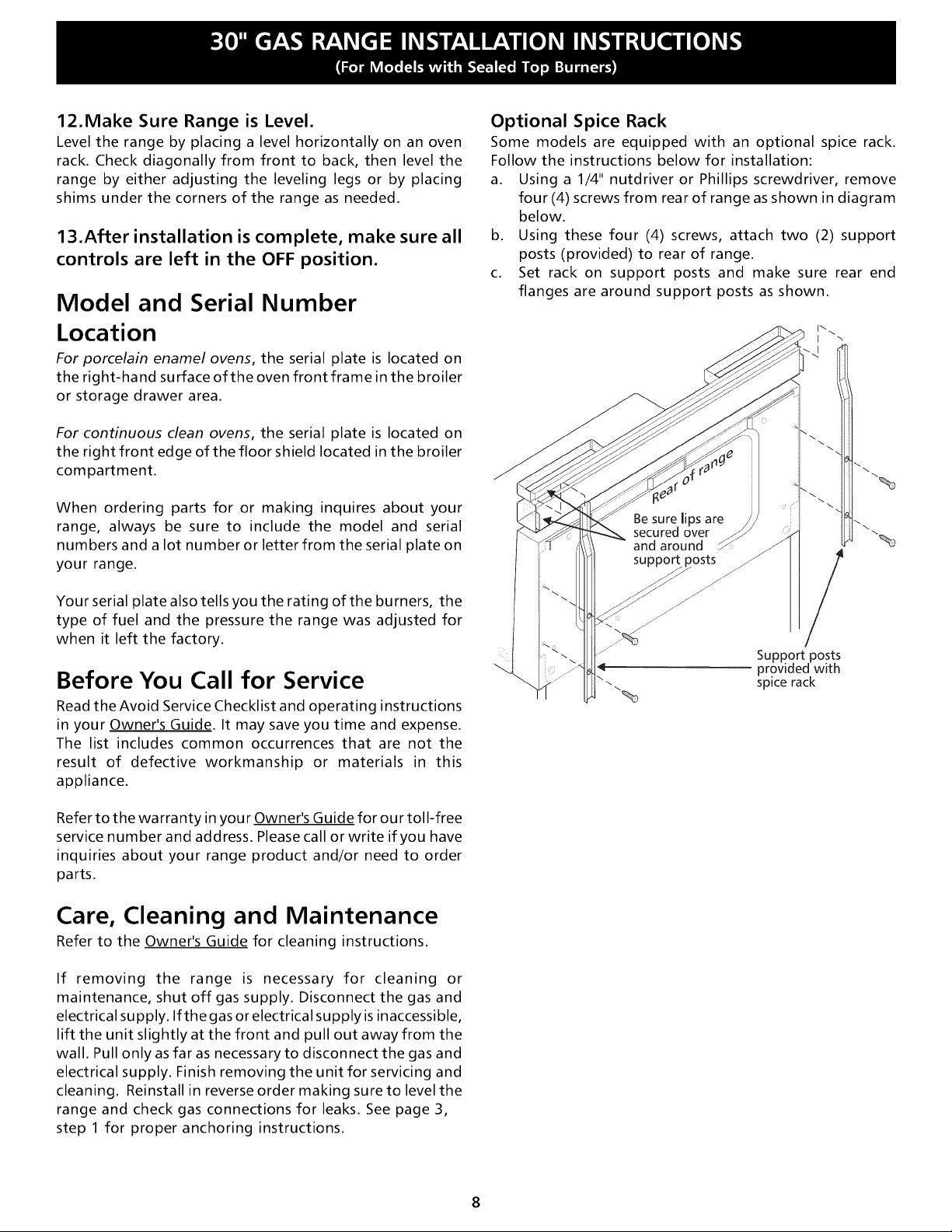
Optional Spice Rack
Some models are equipped with an optional spice rack.
Follow the instructions below for installation:
a. Using a 1/4" nutdriver or Phillips screwdriver, remove
four (4) screws from rear of range as shown in diagram
below.
b. Using these four (4) screws, attach two (2) support
posts (provided) to rear of range.
c. Set rack on support posts and make sure rear end
flanges are around support posts as shown.
Your serial plate also tells you the rating of the burners, the
type of fuel and the pressure the range was adjusted for
when it left the factory.
Before You Call for Service
Read the Avoid Service Checklist and operating instructions
in your Owner's Guide. It may save you time and expense.
The list includes common occurrences that are not the
result of defective workmanship or materials in this
appliance.
Refer to the warranty in you r Owner's Guide for our toll-free
service number and address. Please call or write if you have
inquiries about your range product and/or need to order
parts.
Care, Cleaning and Maintenance
Refer to the Owner's Guide for cleaning instructions.
If removing the range is necessary for cleaning or
maintenance, shut off gas supply. Disconnect the gas and
electrical supply. If the gas or electrical supply is inaccessible,
lift the unit slightly at the front and pull out away from the
wall. Pull only as far as necessary to disconnect the gas and
electrical supply. Finish removing the unit for servicing and
cleaning. Reinstall in reverse order making sure to level the
range and check gas connections for leaks. See page 3,
step 1 for proper anchoring instructions.
/
Support posts
provided with
spice rack
Page 9

L'INSTALLATION ET LES RI_PARATIONS DOIVENT I_TRE EFFECTUI_ES PAR UN TECHNICIEN QUALIFII_.
IMPORTANT • CONSERVER CETTE NOTICE POUR L'INSPECTEUR D'INSTALLATIONS I_LECTRIQUES DE LA
LOCALITE.
LIRE ET CONSERVER CETTE NOTICE POUR RI_FI_RENCE FUTURE.
Toute derogation aux directives donnees dans cette
notice peut entrainer des risques d'incendie, d'explosion, de
dommages materiels, de blessures ou de mort.
POUR VOTRE SI_CURITI_ :
-- Ne pas entreposer ni utiliser d'essence ou d'autre vapeurs ou
liquides inflammables a proximite de cette cuisiniere ou de tout
autre appareil electromenager.
-- QUE FAIRE S'ILYA UNE ODEUR DE GAZ
• N'allumeraucun appareil electrique.
• Ne toucher aucun commutateur electrique; ne pas utiliser le
telephone dans I'immeuble.
• Appeler la compagnie de gaz immediatement en utilisant le
telephone d'un voisin. Suivre les instructions de la compagnie
de gaz.
• S'il est impossible de joindre la compagnie de gaz, appeler les
pompiers.
-- L'installation et les reparations doivent _tre effectuees par un
TOUTES LES
CUISINIERES
PEUVENT
BASCULER.
DES BLESSURES
POURRAIENT
SURVENIR.
INSTALLER LES
AMARRES QUI
ACCOM-
PAGNENT LA
CUISINII_RE.
SE REPORTER
AUX DIRECTIVES
D'INSTALLATION
DES AMARRES.
technicien qualifie, un agent de service ou la compagnie de gaz.
29 7/8" 2 53/8"
48 1/2"
Maximum
avec
tablettes
6pices
47-3/4"
J Maximum"
44 3/8" \\
Porte ouverte \ \
Degagement et dimensions
1, Emplacement--Verifier I'esaace ou la
cuisiniere dolt _tre installee. S'assurer
que I'alimentation en gazet en
electricite est adequate et que le
plancher est stable.
2. Les dimensions indiquees doivent _tre
resDectees. Les dimensions indiquees
stipulent le degagement minimum
requis. Le plancher dolt _tre ferme et
au niveau.
Distance min. du
mur de chaque
c6t6 de la .........
cuisJni_r, au-dessus
de 36" de hauteur.
* Remarque: Un
d6gagement de
3 po est n6cessaire
si la cuisini_re est
dot6e de brOleurs
de 11 000 BTU.
\
30 _ _ Espace de 0" sous la surface de suisson et derriere la cuisini6re,
__Vue De
L'Avant
t Distance min.
I'armoire du
18" haut du c6t6
gauche ou
c
Vue De
C6t6
Profondeur I÷I 3"-_I
armolres slses
au-dessus de
maximum des _-
la cuisini_re.
Prevoir le type de combustible convenable
avant d'aller plus loin:
Votre cuisini_re a 6t6 r6gl6e afin de fonctionner avec du gaz naturel seulement. Certains
modules sont exp6di6s avec des pi_ces de conversion ainsi que des instructions. Deux ou trois
modules comportent un ensemble de conversion au gaz propane/GLP qui peut _tre obtenu
aupr_s du marchand.
Pour les modules dot_s de quatre br01eurs de surface de 9 000 BTU, commandez I'ensemble n°
80-8802-10. Pourlesmod_lesdot6sde2 br01eurs de surface de 9 000BTUetde2de
11 000 BTU, commandez I'ensemble n° 80-8904-10. Pour les modules dot6s de 3 br01eurs de
surface de9 000BTUetdel dell 000BTU, commandezl'ensemblen ° 80-8809-10.
I[-_ _ ' _°_ Ne pas tenter de modifier les r6glages de cette cuisini_re _ des
r6glages pour gaz propane/GLP sans I'ensemble de conversion au gaz propane/GLP appropri6
fourni avec la cuisini_re ou obtenu chez un marchand. Suivez toutes les instructions fournies
avec I'ensemble de conversion.
Page 10

Remarques importantes a I'intention de
I'installateur
1. Lire les directives contenues dans cette notice d'installation
avant d'installer la cuisini_re.
2. Retirer tout le materiel d'emballage de I'int_rieur de la cuisini_re
avant de brancher la cuisini_re _ I'alimentation en gaz et en
_lectricit&
3. Respecter tousles codes et ordonnances qui s'appliquent.
4. Laisser cette notice d'installation au client.
Remarque importante a I'intention du client
1. Conserver cette notice d'installation avec le Guide de I'utilisateur
pour r_f_rence future.
f f
CONSlGNES DE SECURITE
IMPORTANTES
Cette cuisini_re doit 6tre install6e conform_ment aux codes Iocaux
ou, s'il n'existe pas de codes Iocaux, _ 1'6dition la plus r_cente de la
norme ANSI Z223.1 si elle est install6e aux I_tats-Unis. Au Canada,
I'installation doit respecter les normes CAN/CGA-B149.1 et
CAN/CGA-B149.2
_J___ Ne pas monter, s'appuyer ou s'asseoir sur
les portes ou les tiroirs de cette cuisiniere; cela pourrait entrainer
des blessures graves et endommager la cuisiniere,
• Ne pas ranger des articles pouvant attirer des enfants dans
les armoires situees au-dessus de la cuisiniere. Les enfants
pourraient se br01er gravement en grimpant sur la cuisini_re
pour atteindre ces objets.
• II est preferable de ne pas utiliser I'espace de rangement
situe au-dessus des br01eurs de surface pour ne pas avoir
tendre les bras au-dessus de ceux-ce.
• Ajuster I'intensite de la flamme des br6leurs de surface de
fa_on ace qu'elle ne depasse pas le bord de la casserole, Les
flammes trop vives pr_sentent des dangers.
• Ne pas utiliser la cuisiniere comme espace de rangement.
Cela pourrait presenter des dangers.
• Ne jamais utiliser la cuisiniere pour rechauffer ou chauffer la
piece. II est dangereux d'utiliser la cuisini_re de fa_on prolong_e
sans une a_ration suffisante.
• Ne pas entreposer d'essence ou d'autres vapeurs ou liquides
inflammables a proximite de cet appareil ou de tout autre
appareil electromenager, Cela pourrait entrafner une explosion
ou un incendie.
• Remettre tousles boutons de commande a la position _off))
apres avoir utilise une fonction de la minuterie,
La conception de cette cuisini_re a _t_ ag r_e par I'CSA International.
Comme c'est le cas pour tout appareil qui utilise du gaz naturei et qui
_met de la chaleur, certaines consignes de s_curit_ doivent 6tre
respect_es. Ces consignes sont _nonc_es dans le Guide de I'utilisateur;
lire ce guide attentivement.
• S'assurer que la cuisiniere est correctement installee et mise
la terre par un installateur ou un technicien qualifi&
• Cette cuisiniere doit _tre mise a la terre conformement aux
codes Iocaux ou, s'il n'existe pas de codes Iocaux, a I'edition
la plus recente de la norme ANSl/NFPA n° .70 si elle est
installee aux letats-Unis. Au Canada, la mise _ la terre doit
respecter la norme CSA C22.1 du Code de I'_lectricit_ du Canada,
partie 1. Se reporter aux directives de mise _ la terre _ la page 13.
• Avant d'installer la cuisiniere dans un endroit recouvert de
linoleum ou de tout autre couvre-plancher synthetique,
s'assurer que le couvre-plancher peut supporter une chaleur
superieure d'au moins 32,2°C (90°F) a la temperature de la
piece sans retrecir, se tordre ou changer de couleur, Ne pas
installer la cuisini_re sur un tapis _ moins de placer un rev_tement
isolant en contre-plaqu_ de 0,64 cm (1/4 po) entre la cuisini_re
et le tapis.
• S'assurer que le rev_tement des murs qui entourent la
cuisiniere peut supporter la chaleur qu'emet cet appareil.
• Ne pas obstruer la circulation de I'air servant a la combustion
pres de la grille d'aeration ni autour de la base ou sous le
panneau avant de la cuisiniere. I_viter detoucher aux ouvertures
d'a_ration ou aux surfaces avoisinantes car elles peuvent devenir
tr_s chaudes pendant le fonctionnement de la cuisini_re. Cette
cuisini_re a besoin d'air frais pour que la combustion soit
adequate.
POUR LES MODI_LES AUTONETTOYANTS:
• Retirer la lechefrite, la nourriture et tout autre ustensile de
cuisson avant de nettoyer la cuisiniere. Essuyer le surplus de
salet& Suivre les directives de preparation au nettoyage contenues
dans le Guide de I'utilisateur.
• Contrairement a la cuisiniere au gaz standard, LA SURFACE
DE CUISSON DE CETTE CUISlNII_RE N'EST PAS AMOVlBLE, Ne
pas tenter de retirer la surface de cuisson.
NE PAS TENTER DE QUELQUE FA(_ON
QUE CE SOIT D'UTILISER LE FOUR /_ ALLUMAGE I_LECTRIQUE
PENDANT UNE PANNE D'I_LECTRICITI_. EN CAS DE PANNE
D'I_LECTRICITI_, REMETTRE TOUTES LES COMMANDES DU FOUR/_
LA POSITION _<OFF>>.
Si le thermostat du four restait allum6 (position <{ON>>)pendant
une panne d'61ectricit6, I'allumeur _lectrique red_marrerait
automatiquement le brOleur du four une fois la panne r_tablie.
Ne jamais laisser des enfants seuls ou
sans surveillance pres d'un appareil electromenager en marche.
D_s que les enfants sont assez grands, leur enseigner I'utilisation
correcte et s_curitaire de tousles appareils _lectrom_nagers. Ne
jamais laisser la porte du four ouverte Iorsque aucun adulte ne se
trouve _ proximit&
Si la panne d'61ectricit6 survient apr_s I'allumage de I'un des
brOleurs de surface, ce brOleur continuera de fonctionner.
Pendant une panne d'_lectricit_, les brOleurs de surface peuvent
_tre allum_s _ I'aide d'une allumette. Tenir une allumette allum_e
au-dessus du br01eur, puis tourner lentement le bouton vers la
position d'allumage (_LITD>. Faire preuve d'une grande prudence
en allumant les brOleurs de cette fa_on.
10
Page 11

Avant I'installation
Outils requis
Pour mettre les pieds au niveau :
• Cl_ _ douille (1 3/8 po hexagonale) ou pinces multiprise
• Tourne-_crou de 5/16 po ou tournevis _ lame plate
• Perceuse 61ectrique et foret de 1/8 po de diam_tre (foret
ma_onnerie pour une installation dans le b_ton)
Pour le branchement du gaz :
• CI_ _ tuyau
Reglage de la flamme du br[31eur:
• Tournevis Phillips __ et tournevis _ t6te plate
Pour la conversion du type de gaz (gaz propane ou gaz naturel) :
• CI_ ouverte de 1/2 po
Materiel additionnel requis
• Robinet d'arr6t de la conduite de gaz. :_,:_:j
• P_te _ joint qui r_siste _ Faction du gaz propane/gaz de p_trole
liqu_fi_ GPL
Les directives fournies sont pr6vues pour la fixation dans le bois ou
dans le b_ton, dans le plancher ou dans un mur. Lors de I'installation
sur un mur, assurez-vous que les vis traversent compl_tement lemur
sec et qu'elles se fixent dans du bois ou du m_tal. Lors de la fixation
un plancher ou _ un mur, assurez-vous que les vis ne p6n_trent pas
dans du c_blage _lectrique ou des accessoires de plomberie.
A.
Positionnez le support a I'aide du qabarit - (Le support peut
6tre plac_ sur la gauche comme sur la droite de la cuisini_re.
Positionnez le support _ I'aide du schema ci-dessous sile gabarit
n'estpasdisponible.) Faitesunrep_resurleplancherousurle
mur, I_ ou le c6t_ gauche ou le c6t_ droit de la cuisini_re se
trouvera situS. Si I'arri_re de la cuisini_re est contre lemur ou
une distance maximale de 1-1/4 po (3,18 cm) une fois install_e,
vous pouvez recourir _ la m_thode de I'installation au mur ou au
plancher. Siunemoulurevousemp_chedemonterlesupport
contrelemur, enlevez-laoufixezlesupportauplancher. Pour
un montage au mur, situez le support en pla(_ant le bord arri_re
du gabarit contre lemur arri6re, et le bord lat6rai du gabarit sur
le rep6re fait par rapport au c6t_ de la cuisini6re. Placez le
support au-dessus du gabarit et marquez I'emplacement des
trous de vis dans lemur. Si I'arri_rede la cuisini6re est _ plus de
1-1/4 po (3,18 cm) du mur une fois install6e, fixez le support au
plancher. Pour un montageau plancher, situezlesupporten
pla_ant le bord arri_re du gabarit I_ ou sera situ6 I'arri_re de la
cuisini6re. Faites un rep_re des trous de vis indiqu_s sur le
gabarit.
Un nouveau conduit en metal flexible pour appareil menager (1/2
po NPT x 3/4 po ou 1/2 po diam. interieur) dolt &tre certifie selon
une conception CSA International. Etant donne que les tuyaux
rigides ne permettent pas le deplacement facile de la cuisiniere,
nous recommandons I'emploi d'un nouveau tuyau flexible (de 4
5 pieds de Iongueur) pour les nouvelles installations et les
reinstallations supplementaires.
Utilisez toujours les deux (2) nouveaux raccords _ collet (1/2 po
NPT x 3/4 po ou 1/2 po diam. int6rieur) fournis avec le nouveau
tuyau flexible de I'appareil m_nager pr_vu pour raccorder la
cuisini_re.
Etapes d'installation normales
1. Directives de montage du support anti-
renversement
Avertissement important sur la securite
La cuisinini_re dolt 6tre fix6e au plancher pour _viter qu'elle nese
renverse. Ceci se r6alise en installant un support anti-renversement
I'aide des vis fournies avec la cuisini6re. Si le support anti-
renversement n'est pas install6, la cuisini_re peut basculer Iorsqu'un
poids excessif est exerc_ sur une porte ouverte ou qu'un enfant
montedessus. Des blessures graves peuvent s'ensuivre provenant de
la cuisini6re elle-m6me ou du renversement de liquides chauds.
Percez des avant-trous et fixez le support - Percez un avant-
trou de 1/8 po (3,2 mm) I_ ou seront situ_es les vis. Sile support
doit _tre mont_ au mur, percez un avant-trou _ une inclinaison
d'environ 20 ° vers le bas. Si vous installez le support sur un
plancher en c_ramique ou ma(_onnerie, percez un avant-trou de
5/32 po (3,9 mm) _ une profondeur de 1-3/4 po (4,44 cm). Les
vis fournies pourront _tre utilis_es dans le bois comme dans le
b_ton. Utilisezuntourne-_croude5/16poouuntourne-vis
lame plate pour fixer le support en place.
FIXEZLESUPPORT(Montage au rnur ou au plancher)
-_1 1_--1-1/4 po max.
-Montage sur lernur
Lisse
Montage au plancher--_'L!, ipport anti-renversement
F|XEZLESUPPORT(Montage au plan€her seulement)
-_1 Plus de
Piedde 1=1/4 po
i_r_-- Mur
S'il fallait d_placer la cuisini_re _ un autre endroit, les supports anti-
renversement devraient _galement 6tre enlev_s et remont_s _ nouveau
avec la cuisini_re.
Montage au plancher------_ Support anti-renversernent
11
Page 12

C, Placement et mise a niveau de la cuisiniere - Mettez la
cuisini_re _ niveau en r6glant les quatre (4) pieds de nivellement
I'aided'unecl_. Remarque: Und_gagementminimaldel/8
po (3,2 mm) est n_cessaire entre le bas de la cuisini_re et le pied
de nivellement pour Ioger le support. Utilisez un niveau _ bulle
d'air pour v6rifier vos r_glages. Remettez la cuisini_re en place.
V_rifiez visuellement si le pied de nivellement arri_re se trouve
Iog_ et bien fix_ dans le support anti-renversement en enlevant
le panneau inf_rieur ou le tiroir de rangement. Pour les modules
avec tiroir chauffant ou compartiment _ I_chefrite, prenez le
bord arri6re sup_rieur de la cuisini6re et essayez doucement
d'incliner la cuisini6re vers I'avant.
I
Centre de
la cuisini_re
129,21 cm
--_(11-1/2
55,8
(22 p,
Espace recommand_ pour le
branchement du tuyau et du
0binet d'arr_t dans le planchel
La zone ombrag_e
indique I'espace
recommand_ pour la
rise de ! 20 V sur le m_
et I'espace pour le
et du robinet d'arr_t
dans lemur.
2. Assurer une alimentation en gaz adequate.
Cet appareil est con(_u pour fonctionner sur une pression de 10,16 cm
(4 po) produite par un distributeur de gaz naturel. Un r_gulateur de
pression ajustable est branch_ au distributeur; ce r6gulateur DOlT
_tre reli_ en s6rie avec la conduite d'alimentation en gaz. Si un
ensemble de conversion au gaz propane a 6t6 install6, suivre les
directives qui accompagnent I'ensemble en question pour convertir
le r6gulateur de pression _ I'alimentation de gaz propane.
II faut prendre grand soin pendant I'installation de la cuisini_re de ne
pas obstruer la circulation de Fair servant _ la combustion et _ la
ventilation.
Pour que la cuisiniere fonctionne correctement, la pression
d'admission maximum au r6gulateur ne dolt pas d@asser 35,56 cm
(14 po) d'eau. La pression d'admission au r6gulateur dolt _tre d'au
moins 2,54 cm (1 po) plus 61ev6e que la pression au distributeur. Par
exemple, si le r_g ulateur est r_gl_ de fa(_on _ ce que la pression de gaz
naturel soit de 10,16 cm (4 po) au distributeur, la pression
d'admissiondoit6tred'aumoins12,7 cm(5 po).Siler_gulateura
_t6 converti _ une alimentation en gaz propane et que la pression au
distributeur est de 25,4 cm (10 po), la pression d'admission doit
_tred'aumoins27,94 cm (11 po).
Un essai dI_tanch_it_ de I'appareil dolt _tre r_alis_ selon les instructions
fournies _ I'_tape 4g.
Laconduited'alimentationengazdoit_trede1,27 cm(1/2 po) ou
1,9 cm (3/4 po) d.i.
3. Sceller les ouvertures.
Sceller toute ouverture dans lemur, derri6re la cuisini6re, et dans le
plancher, sous la cuisini6re, une fob la conduite d'alimentation en
gaz install_e.
4. Brancher la cuisiniere a I'alimentation en gaz.
Pour pr6venir les fuites, appliquer un mastic de joint pour tuyaux sur
les filets de tousles raccords m_les (filets sur I'ext6rieur).
Le r_gulateur est situ_ dans I'un des deux emplacements illustr_s ci-
dessous.
_!_J___ Ne pas permettre au regulateur detourner
sur le tulau pendant le serrement des pieces,
Front Access
to Regulator:
Remove Kick Panel,
StorageDrawer, or
Warmer Drawer. Pressure
(See Owner's Guide Regulator
for Instructions). location at
If Equipped with rear of
Broiler Drawer,
Broiler Drawer.
12
Page 13

Robinet Adaptateur Connecteur Adaptateur R_gulateur
d'arr_t _ soupie de _ de pression
manuel _vasement I'appareil _vasement
(illustr__ la position {{ONe>(OUVERT).
S'assurerque le levier setrouve & laposition {{ON>>unef0is I'installation termin_e.
5. Lire les directives relatives au branchement
electrique ci-dessous et brancher la cuisiniere
I'alimentation electrique.
E_ _'_ " ' _ Avantlebranchement, couperl'alimentation
_lectrique _ la bofte de fusibles ou de disjoncteurs ou au cordon
d'alimentation.
Installation 61ectrique : D6rivation distincte ad6quatement mise & la
terre et polaris_e avec disjoncteur ou fusible _ retardement de 15 A.
Se reporter _ la plaque signal_tique pour la tension recommand6e.
a) Poser un robinet d'arr6t manuel externe sur la conduite
d'alimentation en gaz dans un endroit facile d'acc_s _ I'ext_rieur
de la cuisini_re. S'assurer de savoir comment et ou couper
I'alimentation en gaz de la cuisini6re.
b) Poser un adaptateur _ _vasement de 1,27 cm (1/2 po) sur le
r6gulateur de pression.
c) Fixer le connecteur de I'appareil _ I'adaptateur _ _vasement reli_
au r6gulateur.
d) Fixer un autre adaptateur _ _vasement au robinet d'arr6t manuel
externe.
e) Fixer le connecteur de I'appareil _ I'adaptateur _ _vasement reli_
au robinet d'arr6t.
f) S'assurer que le robinet d'arr_t du r6gulateur de pression est
ouvert (position _ON_>).
g) V_rifier s'il y a des fuites. Ouvrir I'alimentation en gaz de la
cuisini_re et appliquer un d6tecteur de fuite liquide sur tousles
joints et les raccords de fa_on _ d_celer toute fuite dans la
conduite.
Ne pas utiliser une flamme vive pour d_tecter
les fuites de gaz.
Verifier la pression de gaz du distributeur
D_brancher la cu isin i_re et son robinet d'arr_t distinct de la canalisation
de gaz pendant toute v_rification de pression de I'alimentation en
gaz&despressionsquid6passent35,56 cm(14 po) d'eau(environ
3,45 kPa (1/2 Ib/po2)).
Consignes de s6curit_ relatives aux cordons de rallonge :
En raison des risques que peuvent presenter les cordons de rallonge
dans certaines circonstances, nous recommandons fortement de ne
pas utiliser de cordon de rallonge avec la cuisini_re. Toutefois, si I'on
d_cide tout de m_me d'utiliser un cordon de rallonge, celui-ci dolt
_tre _ 3 conducteurs, agr_ UL, mis _ la terre et con_u pour le
branchement d'appareils _lectrom_nagers; il doit _tre en mesure de
soutenir une tension _quivalente ou sup_rieure _ I'amp_rage de la
d_rivation. On peut se procurer ce type de cordon de rallonge aupr_s
de I'agent de service apr_s-vente agr_ le plus proche.
LIREATTENTIVEMENT ! Pourvotres6curit_,
cet appareil dolt _tre convenablement mis _ la terre.
Mise a la terre
Le cordon d'alimentation _lectrique de cet appareil est pourvu d'une
fiche_ 3 broches (mise_ laterre) quiconvient auxprises murales
standard _ 3 ouvertures mises _ la terre, et ce de fa(_on _ minimiser
les risques d'_lectrocution que pourrait presenter cet appareil. Le
consommateur dolt faire v_rifier la prise murale et le circuit par un
_lectricien agr_ afin de s'assurer que la prise est correctement mise
la terre et polaris_e.
Methode
privil_gi_e
ne faut en aucun cas_
couper, retirer ou |
contourner la broche [
de terre de cette fiche. _
J
L'appareil dolt _tre isol_ de la canalisation de gaz par la fermeture de
son robinet d'arr6t manuel pendant toute v_rification de pression de
la canalisation de gaz _des pressions 6gales ou inf_rieures _ 35,56 cm
(14 po) d'eau (environ 3,45 kPa (1/2 Ib/po2)).
S'il s'av_re n_cessaire de v_rifier la pression de la canalisation de gaz,
brancher un manom_tre (hydrom_tre) ou un autre appareil de
v_rification de pression _ I'orifice du brOleur de surface arri_re droit.
Tenir un boyau en caoutchouc d'environ 0,6 cm (1/4 po) dediam_tre
int_rieur reli_ _ I'appareil de v_rification bien serr_ sur I'orifice. Ouvrir
le robinet du brOleur.
Pour une v_rification de pression fiable, faire fonctionner au moins
deux (2) autres br01eurs de surface pendant la v_rification. S'assurer
que la pression d'alimentation en gaz (pression d'admission) est
sup_rieured'aumoins2,54 cm(1 po)_lapressiondudistributeur.
La pression de I'alimentation en gaz ne dolt jamais _tre sup_rieure
35,56 cm (14 po) d'eau. Lorsque la pression du distributeur est bien
ajust_eaugaznaturel, elleestde10,16 cm (4 po).Danslecasdu
gazpropane, lapressiondudistributeurestde25,4 cm(10 po).
Prise rnurale
mise & la terre
Lorsque la prise murale n'a que deux ouvertures, il incombe au
propri_taire de I'appareil de faire remplacer cette prise par une prise
trois ouvertures convenablement mise _ la terre.
IL NE FAUT EN AUCUN CAS COUPER OU RETIRER LA BROCHE DE
TERRE DU CORDON D'ALIMENTATION ELECTRIQUE.
Cordon
d'alimentation
avec fiche & 3
broches raise
la terre
13
Page 14

Fonctionnement des brOleurs de
surface
Cette cuisini6re est pourvue de br01eurs scell_s, comme le montre
I'illustration qui suit.
Couverde du
br_leur
Languettes
de fixation
Base du Ouvertures de
brOleur fixation
I_lectrode _- .......
Anneau de garniture (certains modules)
ou cuvette du br61eur (certains mod¢les)
7. Br61eurs de surface a allumage electrique
Le fonctionnement de I'allumage _lectrique doit 6tre v_rifi_ une fois
que la d_tection de fuite dans les raccords de la cuisini_re et de la
conduite d'alimentation a _t_ effectu_e et que la cuisini_re a _t_
branch_e _ I'alimentation _lectrique. Les soupapes des br01eurs de
surface sont dot_es d'un encliquetage aux positions <_OFF_>(arr_t) et
<_LITE_>(allumage). II faut enfoncer le bouton et le tourner au-del_ de
ces positions d'encliquetage.
a. Pour v_rifier I'allumage, enfoncer et tourner le bouton d'un
br01eur de surface _ la position _LITE_>.On entend une _tincelle
dans le dispositif d'allumage.
b. Le br01eur de surface devrait s'allumer si I'alimentation en gaz
est reli_e au br01eur. Purger I'air des canalisations d'alimentation
en laissant le bouton _ la position _LITD> jusqu'au moment ou le
br01eur s'allume. Dans des conditions normales, chaque br01eur
devrait s'allumer dans les quatre (4) secondes une lois que Fair
a _t_ purg_ des conduites d'alimentation.
c. V_rifier visuellement si le br01eur est allum_. Une lois le br01eur
allum_, le boutondecommandedoit _treenfonc_ettourn_
hors de la position _LITE_>.
d. Chaque br01eur est pourvu d'un allumeur distinct. V_rifier chacun
des boutons pour tester tousles br01eurs.
Remarque : Le style des boutons peut diff_rer des styles illustr_s.
' l' /
_ HI z!r_/ '_ ii I I I...........
_'_ LiTEi HI _//
6. Installation des pieces qui recouvrent le br61eur
La cuisini6re est pourvue d'anneaux de garniture ou de cuvettes, ou
encore de ces deux dispositifs. Installer les cuvettes (certains modules)
et les anneaux de garniture (certains modules) comme suit '
Grille Q
Couverde Q
J du Br_leur
Anneau de Q
,Garniture
y a lieu)
Cuvette du Q
Br_leur
y a lieu)
Base du BrOleur
Surface de
=Cuisson
Commande Commande
_ deux _ d6bit
positions lin_aire
8. Ajustement du reglage faible ((LOW)) du robinet
des br61eurs (commandes a debit lineaire ou a trois
positions seulement) •
d'almentation
en gaz
a)
Tourner le bouton de commande _ la position _LITE_>jusqu'_ ce
que le brQleur s'allume.
b)
Tourner rapidement la commande _ la POSITION LA PLUS FAIBLE.
c)
Si le brOleur s'_teint, ajuster le robinet de la fa(;on suivante :
Remettre le bouton de commande _ la position (_OFF>>.Retirer le
bouton de commande du brOleur, insurer un tournevis _ lame mince
dans la tige creuse du robinet et saisir la vis _ filets interrompus. La
taille de la flamme peut 6tre augment6e ou r_duite par le r6glage de
cette vis. Ajuster la flamme jusqu'_ ce que le bouton de commande
puisse _tre tourn_ rapidement de la position _LITE_>_ la POSITION LA
PLUS FAIBLE sans que la flamme ne s'_teigne. La flamme doit _tre
aussi petite que possible sans s'6teindre.
Remarque : L'ajustement du m_lange d'air n'est pas requis pour les
brOleurs de surface.
14
Page 15

Fonctionnement des brOleurs du
four et ajustement du four
9. Br_leurs a allumage electrique
Le fonctionnement de I'allumage _lectrique doit 6tre v_rifi_ une fois
que la d6tection de fuite dans les raccords de la cuisini_re et de la
conduite d'alimentation a 6t_ effectu_e et que la cuisini_re a _t_
branch_e _ I'alimentation _lectrique.
Le brOleur du four est pourvu d'un dispositif de contr61e 61ectrique
ainsi que d'un dispositif d'allumage _lectrique. Si la cuisini_re est
pourvue d'un brOleur de grillage _ hauteur de la taille, ce brOleur
dispose 6galement d'un dispositif d'allumage 61ectrique. Cesdispositifs
de contr61e n'ont pas _6tre ajust_s. Une fois le four pr6t _ fonction ner,
I'alimentation 61ectrique se rend au dispositif d'allumage. Ce dispositif
{{s'illumine>> comme une ampoule 61ectrique. Lorsque le dispositif
d'allumage atteint la temp6rature requise pour enflammer le gaz, le
robinet _ commande 61ectriq ue du four s'ouvre et la flamme se forme
sur le brOleur. II fautde30 _ 60 secondes entrele moment ou le
thermostat est allum_ et I'apparition de la flamme sur le brOleur.
Lorsque le four atteint la tem p6rature pr6vue, le dispositif d'allumage
s'_teint. La flamme du brOleur s'_teint dans les 20 _ 30 secondes qui
suivent la fermeture du dispositif d'allumage. Pour maintenir une
temperature donn_e dans le four, le cycle se poursuit tant que la
commande (ou le voyant) fonctionne.
Une fois tout le materiel d'emballage et la documentation sortis du
four:
a) R_gler le four sur CUISSON {_BAKE>>_ 154°C (300°F). Se reporter
au Guide de I'utilisateur pour les directives de fonctionnement.
b) LebrOleurdu fourdevraits'allumerdansles 60 secondesqui
suivent. S'assurer que la flamme est adequate et permettre au
brOleur d'accomplir un cycle complet. Refermer les boutons de
commande (position <{offl>).
c) Si la cuisini_re est pourvue d'un brOleur de grillage _ hauteur de
la taille, r6gler le four sur GRILLAGE <{BROID>. Se reporter au
Guide de I'utilisateur pour les directives de fonctionnement.
d) LebrOleurdegrillagedevraits'allumerdansles60 secondesqui
suivent. S'assurer que la flamme est adequate. Refermer les
boutons de commande.
LaflammedubrOleurdufourmesureenviron2,5 cm(1 po)(flamme
int_rieure de couleur bleue).
Pour d6terminer si la flamme du brOleur du four est ad6quate, retirer
le fond du four et le d_flecteur, puis r_gler le four sur CUISSON
_BAKD> _ 1 54°C (300°F).
Pour retirer le fond du four, enlever les vis de support situ_es sur sa
partie arri_re. Le soulever par I'arri_re, d_sengager son devant du
cadre avant du four, puis le tirer pour le sortir du four. Retirer le
d_flecteur de fa_on _ pouvoir observer la flamme.
Si la flam me est de couleur jaune, accroftre I'ouverture de I'obturateur
d'air. (Se reporter au num6ro 2 de I'illustration qui suit.) Si la flamme
est d'un bleu marque, r6duire I'ouverture de I'obturateur d'air.
Pour ajuster la flamme, desserrer la vis de blocage (se reporter au
num6ro 3 de I'illustration qui suit), ajuster I'obturateur d'air, puis
resserrer la vis de blocage. Remettre le fond du four en place.
_ Tuyau du
br_leur
du four
®v,sdob,oca0o®
(_ Obturateur d'air _ Capuchon
...........i_1
11.0bturateur d'air/ br61eur de grillage (s'il y a
lieu)
LaflammedubrOleurdufourmesureenviron2,5 cm(1 po)(flamme
int_rieure de couleur bleue).
de I'orifice
I
10. Obturateur d'air/br_leur du four
BrOleur _ hauteur
L
D_flecteur
inf_rieur ,-'_'-
du four amovible ,,-'"
_m=Obturateur d'air (amovible)
del le taille (modUles
autonettoyants)
Pour d6terminer si la flamme du brOleur de grillage est adequate,
r_gler le four sur GRILLAGE {_BROID>.
Si la flam me est de couleur jaune, accroftre I'ouverture de I'obturateur
d'air. (Se reporter au num6ro 2 de I'illustration qui pr6c_de.) Si la
flamme est d'un bleu marque, r_duire I'ouverture de I'obturateur
d'air.
Pour ajuster la flamme, desserrer la vis de blocage (se reporter au
num_ro 3 de I'illustration qui precede), ajuster I'obtu rateu r d'air, puis
resserrer la vis de blocage.
d'air
Fond du four
15
Page 16

12. S'assurer que la cuisiniere est au niveau
Mettre la cuisini_re au niveau en pla_ant un niveau _ I'horizontale sur
une gille du four. V_rifier en diagonale d'avant en arri_re, puis mettre
la cuisini_re au niveau, soit en ajustant les pieds de nivellement, soit
en pla_ant des cales sous les coins au besoin.
13. Une fois I'installation terminee, s'assurer que
tous les boutons de commande sont fermes
(position (_off))).
Emplacement des num ros de
module et de s rie
Dans le cas des fours 6maill6s, la plaque signal6tique est situ_e sur le
bord avant droit du cadre du four, dans le compartiment du grilloir
ou le tiroir de rangement.
Dans le cas des fours b nettoyage continu, la plaque signal_tique est
situ6e sur le bord avant droit du protecteur de plancher situ_ dans le
compartiment du grilloir.
Lorsqu'il faut commander des pi6ces ou poser des questions sur la
cuisini_re, s'assurer de mentionner le num6ro de module et le num_ro
de s_rie ainsi que le num_ro de lot ou la lettre qui figurent sur la
plaque signal_tique de la cuisini6re.
Installer le support a epices.
Ce four est _quip_ d'un support _ _pices _ ajouter ou non, au choix.
Pour affixer-le sur la cuisini_re:
a. Avec un tournevis Phillips, enlever quatres (4) vis de la derriere
de la cusini_re comme idinqu_ ci-dessous.
b. Employant ces quatres (4) vis, rattacher les deux colonnes de
soutient (fournis) _ I'arri_re de la cuisini_re.
c. Placer le support _ _pices sur les poteaux de soutient en tant que
les rebords entourent les poteaux de soutient comme indiqu_ ci-
dessous.
La plaque signal_tique indique _galement le calibre des brOleurs, le
type de carburant _ utiliser et la pression pr_ajust_e au moment ou
la cuisini_re a quitt_ I'usine.
Avant de faire appel b un centre de
service
Lire le Guide de d_pannage et les directives d'utilisation qui figurent
dans le Guide de I'utilisateur. Cela peut _pargner du temps et des
d_penses inutiles. Le Guide de d_pannage d_crit les probl_mes
courants qui ne sont pas causes par un vice de fabrication ou de
mat_riaux.
Se reporter _ la garantie qui figure dans le Guide de I'utilisateur pour
connaftre le num_ro sans frais et I'adresse de notre service _ la
clientele. N'h_sitez pas _ nous appeler ou _ nous _crire si vous avez
des questions au sujet de votre cuisini_re ou pour commander des
pi_ces.
Entretien et nettoyage
Se reporter au Guide de I'utilisateur pour les directives de nettoyage.
S'il faut d6placer la cuisini_re pour la nettoyer ou la r_parer, fermer
I'alimentation en gaz. D_brancher I'alimentation en gaz et
I'alimentation 61ectrique. Si les sources de gaz et d'_lectricit6 ne sont
pas accessibles, soulever I_g_rement le devant de la cuisini_re et tirer.
Tirer juste assez pour _tre en mesure de couper I'alimentation en gaz
et en _lectricit_. Poursuivre le d6placement de la cuisini6re pour
I'entretien ou le nettoyage. R6installer la cuisini6re dans I'ordre
inverse en s'assurant qu'elle est au niveau et qu'il n'y a pas de fuite
dans les raccords dela conduite degaz. Sereporter au dela page 11
pour savoir comment amarrer correctement la cuisini6re.
/
Pied supports
fournis avec les
tablettes & _pices
16
Page 17

LA INSTALAClON Y EL SERVIClO DEBEN SER EFECTUADOS POR UN INSTALADOR CALIFICADO.
IMPORTANTE: CONSERVE ESTAS INSTRUCClONES PARA USO DEL INSPECTOR LOCAL DE ELECTRIClDAD.
LEA Y CONSERVE ESTAS INSTRUCClONES PARA REFERENClA FUTURA.
Si la informacion contenida en este manual no es
seguida exactamente, puede ocurrir un incendio o explosion
causando daEos materiales, lesion personal o la muerte.
PARA SU SEGURIDAD:
-- No almacene ni utilice gasolina u otros vapores y liquidos
inflamables en la proximidad de este o de cualquier otro
artefacto.
-- QUE DEBE HACER Sl PERClBE OLOR A GAS:
• No trate de encender ningun artefacto.
• No toque ningun interruptor electrico; no use ningun telefono
en su edificio.
• Llame a su proveedor de gas desde el telefono de un vecino.
Siga las instrucciones del proveedor de gas.
• Si no Iogra comunicarse con su proveedor de gas, Ilame al
departamento de bomberos.
-- La instalacion y el servicio de mantenimiento debe realizarlo
un instalador calificado, la agencia de servicios o el proveedor
de gas.
• TODAS LAS
ESTUFAS
PUEDEN
VOLCARSE.
• PUEDEN
RESULTAR
LESIONES
PERSONALES.
• INSTALE EL
DISPOSITIVO
ANTIVUELCO
EMPACADO
CON LA ESTUFA.
• VEA LAS
INSTRUCCIONES
DE
INSTALACION.
Espacios libres y dimensiones
1. Ubicacion - Examine la ubicacion donde
va a instalar la estufa. Compruebe que la
alimentacion el_ctrica y de gas sea
adecuada ycompruebe la estabilidad del
piso.
2.
Las dimensiones que se muestran deben
ser usadas. Las dimensiones dadas
proporcionan el espacio minimo
necesario. Lasu perficie de contacto debe
ser solida y nivelada.
VISTA DE
pared en cada
Minimo a ,a __ FRENTE
lado de la estufa
sobre una altura o
* Nota: Sedebe
dejar un espacio
libre de 3' si est_
equipada con Minimo a los
quemadores en la _,, , 18" armarios en
tapa de la estufa L
dede36,, _ /._ la estufa
11,000 BTU
cada lado de
VISTA
LATERAL
Profundidad I÷13"_1
m_xima de los
armarios sobre
la cubierta de
la estufa.
_25,_
I_----
30" _ Espacio fibre de 0" debajo de la cubierta yen la parte
Utilice el tipo de combustible apropiado
Antes de proceder:
Suestufa ha sido dise_ada para funcionar con gas natural solamente. Algunos modelos pueden
ser transformados y se envian con las piezas y las instrucciones de conversion. Otros modelos
tienen un juego de conversion a propano liq uido que puede obtener a trav_s de su distribuidor.
Para los modelos equipados con quemadores de superficie de 4-9.000 BTU, solicite el juego
#80-8802-10. Para los modelos equipados con quemadores de superficie de 2-9.000 BTU y 2-
11.000 BTU, solicite el juego #80-8904-10. Para los modelos equipados con quemadores de
superficie de 3-9.000 BTU y 1-11.000 BTU, solicite el juego #80-8809-10.
NO intente convertir esta estufa a propano liquido sin tener el juego de
conversion a propano liquido suministrado con la estufa u obtenido de su distribuidor. Siga las
instrucciones incluidas con el juego de conversion.
trasera de la estufa.
17
Page 18

D A D A
Importantes notas para el instalador
1. Lea todas las instrucciones contenidas en estas instrucciones
para la instalacion antes de instalar la estufa.
2. Saque todos los materiales de embalaje de los compartimientos
del horno antes de conectar la alimentacion de gas y electricidad
a la estufa.
3. Observe todos los codigos y ordenanzas en vigor.
4. Aseg0rese de dejar estas instrucciones al cliente.
Nota importante para el cliente
1. Guarde estas instrucciones con la guia del propietario para
referencia futura.
IMPORTANTES
INSTRUCCIONES DE
SEGURIDAD
La instalacion de esta estufa debe estar conforme con los codigos
locales, o si no existen c6digos locales, con el National Fuel Gas Code
(Codigo Nacional para Gases Combustibles), ANSI Z223.1--1a edicion
m_s reciente cuando se instala en los Estados Unidos. Si se instala en
Canada, la instalacion debe estar conforme con CAN/CGA-B149.1 y
CAN/CGA- B149.2.
El dise_o de esta estufa ha sido certificado por la CSA International.
Igual que con cualquier electrodom_stico que utiliza gas y genera
calor, existen ciertas precauciones de seguridad que debera seguir.
Las encontrar_ en la Guia del Propietario. L_alas con atencion.
• Asegurese de que su estufa sea instalada y puesta a tierra
debidamente por un instalador capacitado o un tecnico de
servicio,
• Esta estufa debe ser puesta a tierra de acuerdo con los
codigos locales, o si no existen codigos locales, con el
National Electrical Code (Codigo Electrico Nacional), ANSI/
NFPA N° 70 -- la edicion mas reciente cuando se instala en
los Estados Unidos. Si se instala en Canada, esta estufa debe ser
puesta a tierra de acuerdo con la Norma CSA Standard C22.1,
Canadian Electrical Code (Codigo El_ctrico Canadiense), Parte 1.
Vea las instrucciones para la puesta a tierra en la p_gina 21.
• Antes de instalar la estufa en un area cubierta con linoleo o
cualquier otro material de recubrimiento sintetico para
pisos, asegurese de que el recubrimiento para pisos pueda
soportar una temperatura de por Io menos 90°F (32,2°C) por
encima de la temperatura ambiente sin encogerse, doblarse
ni cambiar de color. No instale la estufa encima de un alfombrado
a menos que coloque una alfombrilla o I_mina aislante de
madera chapada de 1/4 de pulgada (6,3 mm) de espesor entre la
estufa y el alfombrado.
• Asegurese de que el papel tapiz de paredes alrededor de la
estufa pueda soportar el calor generado por la estufa.
• No obstruya el paso de aire de combustion en la rejilla de
ventilacion del horno ni alrededor de la base ni debajo del
panel delantero inferior de la estufa. Evite tocar las aberturas
de ventilacion o las superficies cercanas ya que pueden calentarse
cuando el horno est_ en funcionamiento. Esta estufa requiere
aire fresco para la combustion adecuada del quemador.
_: -w, - _ = No deje nunca a los ni_os solos o
desatendidos en el area donde un electrodomestico este en
funcionamiento. Cuando los ni_os crezcan, ens_eles el uso correcto
yseguro de todos los electrodom_sticos. No deje nunca la puerta del
horno abierta cuando la estufa est_ desatendida.
Subirse, apoyarse o sentarse sobre las
puertas o cajones de esta estufa puede provocar lesiones de
consideracion y tambien puede da_ar la estufa,
• No almacene articulos de interes para los ni_os dentro de los
armarios situados por encima de la estufa. Los ni_os que se
suban a la estufa para alcanzar articulos podrian resultar
gravemente quemados..
• Para eliminar la necesidad de colocarse sobre los quemadores
de la superficie, deben evitarse los armarios por encima de
los quemadores.
• Ajuste el tama_o de la llama del quemador de superficie
para que no sobrepase el borde del utensilio de cocina, Las
llamas excesivas son peligrosas.
• No use el horno para almacenar cosas, Esto crea una situacion
peligrosa potencial.
• No use nunca su estufa para mantener un cuarto caliente ni
para calentarlo. El uso prolongado de la estufa sin ventilacion
adecuada puede ser peligroso.
• No guarde ni utilice gasolina ni otros vapores y liquidos
inflamables en las cercanias de este o cualquier otro
electrodomestico, Pueden ocurrir incendios o explosiones.
• Vuelva a colocar todos los controles en la posicion de "off"
(apagado) despues de haber utilizado una operacion con el
programador,
PARA MODELOS CON LA CARACTERISTICA DE
AUTOLIMPIEZA:
• Saque la bandeja del asador, los alimentos y cualquier otro
utensilio antes de poner en marcha la autolimpieza. Limpie
el exceso de derrames de comida. Siga las instrucciones para la
limpieza previa en la Guia del Propietario.
• A diferencia de las estufas a gas communes, LA TAPA DE LA
ESTUFA NO ES REMOVlBLE, No trate de sacar la tapa.
['' " _' _ = NO TRATE DE UTILIZAR EL ENCENDIDO
ELECTRICO DURANTE UNA FALLA DEL SUMINISTRO ELECTRICO.
COLOQUE TODOS LOS CONTROLES DEL HORNO EN "OFF"
(APAGADO) EN CASO DE UNA FALLA ELECTRICA.
El encendedor el_ctrico volvera a encender
autom_ticamente el quemador del horno cuando regrese el
suministro el_ctrico si el control del termostato del horno se dejo
en la posicion de "ON" (encendido).
Cuando ocurra una falla el_ctrica durante el uso, los quemadores
de superficie continuar_n funcionando.
Durante una falla el_ctrica, los quemadores de superficie pueden
ser encendidos con una cerilla. Sujete una cerilla encendida justo
al lado del quemador y gire despacio la perilla a la posicion de LITE
(encendido). Tenga muchisimo cuidado cuando encienda los
quemadores de esta manera.
18
Page 19

Antes de comenzar
Herramientas necesarias
Para las patas niveladoras:
• Herramienta para insertar casquillos (1-3/8" hex) o alicates
channel lock
• Llave para tuercas de 5/16"o Destornillador para tornillos de
cabeza plana (E_Z_]_
• Taladro el_ctrico y broca de 1/8" de di_metro (broca de alba_ileria
si est_ instalando en hormigon)
Para la conexion de la alimentacion de gas:
• Llave para tuberias
Para ajustar la llama del quemador:
• Destornillador phillips y destornillador para tornillos de cabeza
plana .....
Para conversion del gas (LP/propano o natural):
• Llave de boca abierta de 1/2
Materiales adicionales necesarios
• V_lvula de cierre de la linea de gas _
• Sellador de juntas de tuberias que resista la accion del gas
Propano liquido
• Un conducto flexible met_lico nuevo para electrodom_sticos
(1/2" NPT x 3/4" o 1/2" de di_metro interior) certificado por CSA
International. Debido a que la tuberia solida restringe el
movimiento de la estufa, recomendamos quese use un conducto
flexible nuevo (4 a 5 pies de largo) para cada nueva instalacion
y reinstalaciones adicionales.
A.
Ubique el soporte usando la plantilla - (el soporte puede
encontrarse en el lado derecho o izquierdo de la estufa. Utilice
el diagrama siguiente para ubicar el soporte si la plantilla no est_
disponible.) Marque en el piso o en la pared donde quedar_
ubicado el borde derecho o izquierdo de la estufa. Si la parte
trasera de la estufa est_ contra la pared o no est_ a m_s de 1-1/
4" de la pared, usted puede usar el m_todo de montaje en el piso
o en la pared. Si tiene moldura instalada que no permite que el
soporte quede a ras contra la pared, retire la moldura o instale
el soporte en el piso. Para instalacion en la pared, ubique el
soporte colocando el borde trasero de la plantilla contra la pared
trasera y el borde lateral de la plantilla en la marca hecha que
muestra el lado de la estufa. Coloque el soporte arriba de la
plantilla y marque la ubicacion de los agujeros de los tornillos en
la pared. Si la parte trasera de la estufa ya instalada est_ a m_s
de 1 -1/4" de la pared, instale el soporte en el piso. Para montaje
en el piso, ubique el soporte colocando el borde trasero de la
plantilla donde quedar_ ubicada la parte trasera de la estufa.
Marque la ubicacion de los agujeros de los tornillos, mostrados
en la plantilla.
B,
Taladre agujeros pilotos e instale el soporte - Taladre un
agujero piloto de 1/8" donde se van a instalar los tornillos. Si el
soporte va a ser instalado en la pared, taladre el agujero piloto
a un _ngulo descendente de aproximadamente 20 °. Si el soporte
va a ser instalado en pisos de alba_ileria o cer_mica, taladre un
agujero piloto de 5/32" de 1-3/4" de profundidad. Los tornillos
provistos pueden ser usados en pisos de madera o concreto. Use
una Ilave para tuercas de 5/16"0 un destornillador de hoja plana
para asegurar el soporte en su lugar.
ASEGURE EL SOPORTE (MONTAJEENLAPARED0ENELP|SO)
_1 I_- 1-1/4" M_x
Siempre use los (2) adaptadores de union abocinados nuevos
(1/2" NPT x 3/4"o 1/2" de di_metro interior) suministrados con el
conducto flexible nuevo para electrodom_sticos, para la conexion
de la estufa.
Pasos de la Instalacion Normal
1. Instrucciones para la instalacion del soporte
antivuelco
Advertencia de Seguridad Importante
A fin de reducir el riesgo de que la estufa se vuelque, _sta debe ser
asegurada al piso mediante la instalacion adecuada de un soporte
antivuelco usando los tornillos incluidos con la estufa. Si no se instala
el soporte antivuelco la estufa puede volcarse si se coloca peso
excesivo en una puerta abierta o si un ni_o se sube a ella. Se puede
producir una lesion grave a causa del derrame de liquidos calientes
o de la estufa misma si se vuelca.
Si la estufa es cambiada a otro lugar, los soportes antivuelco pueden
tambi_n ser cambiados e instalados con la estufa.
Las instrucciones son para instalacion en madera o cemento y anclaje
al piso o a la pared. Cuando se instala en la pared, asegOrese de que
los tornillos penetren completamente ei muro seco y que est_n
asegurados en madera o metal. Cuandoseasegura al piso o a la
pared, asegOrese de que los tornillos no toquen ningOn alambrado
el_ctrico o tuberias.
19
- Montaje en la pared
_laca mura
Montaje en el piso
ASEGURE EL SOPORTE (MO_TAJEE_ ELPJSOSOLAMENTE)
Para Niveladora -- _'- 1=1/4"
i i
Montaje en el piso _oporte Antivuelco
Soporte Antivuelco
i _k-_--Pared
Page 20

C.
Nivele y posicione la estufa - Nivele la estufa ajustando las
cuatro (4) patas niveladoras con una Ilave. Nota: Sedebe dejar
un espacio libre de por Io menos 1/8" entre la parte inferior de la
estufa y la pata niveladora a fin de que quede espacio para el
soporte. Use un nivel de burbuja para verificar los ajustes.
Deslice la estufa de nuevo a su lugar. Verifique visualmente si la
pata niveladora trasera est_ bien insertada y asegurada en el
soporte antivuelco, retirando el panel inferior o el cajon de
almacenamiento. Para los modelos con un compartimiento
calefactor o compartimiento de asador, sujete la estufa desde el
borde superior trasero y trate de inclinarla hacia adelante
cuidadosamente.
(17ram) " -. _i
22'
I
Lnea central I
de la estufa
!
i rea recomendada para el_
tomacorriente de 120V en
la pared de atras y area
para pasar la tuberia de
conexion a traves de la
para\ed y para la valvula de
cierre, es el area en sombra_
IBorde marcado \ ....
de la estufa
2. Proporcione una fuente entacion de gas
adecuada.
Esta unidad ha sido ajustada para operar con un m_ltiple de admision
para gas natural de 4". Un regulador de presion convertible esta
conectado a la v_lvula distribuidora y DE BEser conectado en serie con
la tuberia de sumibistro de gas. Si el juego de conversion a propano
liquido ha sido usado, siga las instrucciones provistas con el juego
para convertir el regulador de presion para uso con propano liquido.
Se debe tener cuidado durante la instalacion de la estufa para no
obstruir el flujo de combustion y la ventilacion.
Para la operaciOn apropiada, la m_xima presion de entrada al
regulador no debe exceder la presion de una columna de agua de
14 pulgadas. La presion de entrada ai regulador debe ser por Io
menos 1 pulgada m&s grande que la v&lvula distribuidora. Ejemplos:
Si el regulador ha sido ajustado para gas natural a 4 pulgadas de
presion para la v&lvula distribuidora, la presion de entrada debe ser
por Io menos de propano 5 pulgadas; si ei regulador ha sido
convertido a propano liquido a 10 pulgadas de presion para la
v&lvula distribuidora, la presion de entrada debe ser por Io menos de
11 pulgadas.
La prueba de escapes en el artefacto se deber_ efectuar de acuerdo
con las instrucciones en ei paso 4g.
La linea de alimentacion de gas debe tener 1/2" o 3/4" de D.I.
Area recomendada para pasar la') _ _ _4--
tuberia de conexion a traves del /
piso para la valvula de cierre. J
Borde de
la pared
3. Selle las aberturas.
Selle cualquier abertura en la pared detr_s de la estufa yen el piso
debajo de la estufa una vez que haya instalado la linea de alimentacion
de gas.
4. Conecte la estufa a la alimentacion de gas.
Para evitar fugas, ponga un sellador para juntas de tuberias en todas
las roscas macho (exteriores) de la tuberia.
El regulador esta ubicado en el area mostrada mas a bajo.
No permita que el regulador gire sobre la
tuberia cuando apriete los ajustes.
Front Access
to Regulator:
Remove Kick Panel,
StorageDrawer0 or
Warmer Drawer,
(See Owner's Guide
for Instructions).
If Equipped with
Broiler Drawer,
Pressure
Regulator
location at
rear of
ranc
2O
Page 21

V_lvuJa Uni6n Conducto Uni6n Regulador
manual abocinada flexible para abocinada de presi6n
de cierre electrodom_sticos
AsegOrese de que la palanca est6 en la posicibn "ON"
(Mostrada en la posicion "ON")
una vez que se haya completado la instalaci6n
a) Instale una v_lvula manual de cierre en la linea de alimentacion
de gas en un lugar de f_cil acceso fuera de la estufa. AsegOrese
de saber como y donde cerrar la alimentacion de gas de laestufa.
b) Instale un adaptador para union abocinada de 1/2" en el regulador
de presion.
c) Acople el conector para electrodom_sticos a la union abocinada
del regulador.
d) Instaleun adaptador para union abocinada en lav_lvula manual
externa de cierre.
e) Acople el conector para electrodom_sticos a la union abocinada
de la v_lvula de cierre.
f) AsegOrese deque la v_lvula de cierre para servicio en el regulador
de presion est_ en la posicion de "ON" (encendido).
g) Compruebe que no haya fugas. Abra la alimentacion de gas de
la estufa y use un detector de fugas liquido en todas las juntas
y conexiones para ver si hay fugas en el sistema.
No use fuego para comprobar si hay fugas de
gas.
Comprobacion de la presion de gas del multiple
Desconecte la estufa y su v_lvula de cierre individual del sistema de
la tuberia de alimentaci6n de gas cuando vaya a realizar cualquier
prueba de presi6n de ese sistema con presiones de prueba mayores
a 14 pulgadas de presion de columna de agua (aproximadamente
1/2 libra por pulgada al cuadrado manom_trica).
5. Lea los detalles siguientes sobre la conexion
electrica y conecte la electricidad a la estufa.
z _,a ' r" Antes de hacer cualquier reparacion o
mantenimiento, desconecte la alimentacion el_ctrica en ei disyuntor,
fusible o cable.
Requisitos el_ctricos: un circuito derivado individual, correctamente
polarizado y con toma de tierra protegido por un disyuntor o fusible
con retardo de 15 amperios. Vea la placa con ei numero de serie para
el voltaje adecuado.
Precauciones con los cables de extension: dado que existen posibles
riesgos bajo ciertas condiciones, recomendamos con insistencia no
usar ningOn cable de extension. Sin embargo, si usted prefiere usar
un cable de extension, es absolutamente necesario que sea un cable
de extension para electrodom_sticos, con conexion a tierra, trifilar, y
listado por UL, y que la capacidad de corriente del cable en amperios
sea equivalente o mayor a la capacidad dei circuito derivado. Estos
cables de extension est_n disponibles a trav_s de la organizacion local
de servicio.
_ "'" ' iPOR FAVOR LEA CON ATENCION! Para
seguridad personal, este producto debe ser conectado a tierra
adecuadamente.
Instrucciones para la toma de tierra
El cable de este electrodom_stico est_ equipado con un enchufe (de
toma de tierra) con 3 clavijas que entra perfectamente en un
tomacorrientes est_ndar de pared para 3 clavijas con toma de tierra
para minimizar la posibilidad de descargas el_ctricas causadas por
este electrodom_stico. El cliente deber_ pedir a un electricista
ca pacitado q ue examine el tomacorrientes y elcircuito para asegurarse
de que el tomacorrientes est_ debidamente conectado a tierra y
polarizado.
M&todo Preferido
ninguna circun-
Debe aislar la estufa del sistema de la tuberia de alimentacion de gas
cerrando su v_lvula de cierre manual individual siempre que haga
cualqu ier prueba de presion en el sistema de la tu beria de alimentacion
con presiones de prueba equivalentes a 14 pulgadas de presion de
columna de agua o menos (aproximadamente 1/2 libra por pulgada
al cuadrado manom_trica).
Si fuera necesario comprobar la presion de gas del multiple, conecte
un manometro (indicador de nivel de agua) u otro dispositivo de
presion en el orificio del quemador de la parte posterior derecha
superior. Utilice una manguera de caucho con un di_metro interior
de aproximadamente 1/4" y mantenga la manguera bien apretada
sobre el orificio. Abra la v_lvula del quemador.
Para Iograr una presion exacta, compruebe que haya por Io menos
otros dos (2) quemadores superiores con fuego. AsegOrese de que la
presion (de entrada) de la alimentacion de gas est_ por Io menos a 1
pulgada por encima de la presion especificada para el multiple de la
estufa. La presion de la alimentacion de gas nunca deber_ ser
superior a 14 pulgadas de presion de columna de agua. Cuando est_
correctamente regulada para ei gas natural, la presion dei multiple es
de 4". Para ei gas propano/LP la presion dei multiple es de 10".
Tomacorriente con enchufe de tres
de pared con espigas para
conexi6n a tierra puesta a tierra.
Cord6n el_ctrico
Si solo se dispone de un tomacorrientes de pared est_ndar para dos
clavijas, el cliente tendr_ la responsabilidad y la obligacion de
reemplazarlo con un tomacorrientes de pared para tres clavijas con
puesta a tierra.
NO CORTE NI SAQUE BA.JO NING UNACIRCUNSTANCIA LATERCERA
CLAVlJA (DE TOMA DE TIERRA) DEL CABLE.
21
Page 22

Funcionamiento de los
Quemadores Superiores
Esta estufa esta equipada con quemadores sellados como se muestra
m_s abajo.
Tapa del
Quemador
Leng6etas
de Posicion
Base del Ranuras de
Quemador i Position
I
7. Quemadores Superiores de Encendido El6ctrico
Se debe revisar el funcionamiento de los encendedores el_ctricos
despu_s de que la estufa y los conectores de la tuberia de suministro
han sido cuidadosamente revisados para verificar fugas y la estufa ha
sido conectada a la energia el_ctrica. Las v_Ivulas del gas de los
quemadores superiores tienen posiciones de detencion en las
posiciones "OFF" y "LITE'. La perilla debe ser oprimida para que
pueda ser girada m_s all_ de estas posiciones de detencion.
a. Para verificar el encendido adecuado, oprima y gire la perilla de
un quemador superior a la posicion "LITE'. Usted oira el ruido de
las chispas del encendedor.
b. El quemador superior debe encenderse cuando llega gas al
quemador superior. Purgue el aire de las tuberias de suministro
dejando la perilla en la posicion "LITE" hasta que el quemador se
encienda. Todos los quemadores deben encenderse dentro de
cuatro (4) segundos en funcionamiento normal despu_s de que
el aire ha sido purgado de la tuberia de suministro.
c. Verifique visualmente si se encendio el quemador. Una vez que
el quemador se enciende, la perilla de control debe ser oprimida
hacia adentro y girada para sacarla de la posicion "LITE'.
d. Hay electrodos (encendedores) separados para cada quemador.
Pruebe cada perilla separadamente hasta que todas las v_Ivulas
de los quemadores hayan sido revisadas.
Nota: Los estilos de perillas pueden ser distintos a los que se ilustran
a continuacion.
Anillo (algunos modelos)
Platillo del Quemador (algunos modelos
6. Instalacion yArmado de la Tapa del Quemador
Su estufa puede estar equipada con anillos o platillos del quemador,
o anillos y platillos del quemador. Instale los platillos (algunos
modelos) y los anillos (algunos modelos) de la siguiente forma:
Parrilla
Tapa del G
f Quemador
Annillo de
Guarnicion
est_ equipado)
Bandeja del (_
Quemador
est_ equipado)
Base de
Quemador
Superficie
de la Cubierta
' I' I
Valvula VaNula
de dos de flujo
posiciones lineal
8. Regule el ajuste "LOW" (BAJO) para las valvulas
del quemador superior:
%.
At Quemador
Superior
Prueba para verificar si el ajuste "LOW" debe ser regulado.
a. Oprima y gire la perilla de control a LITE hasta que el
quemador se encienda.
b. Oprima y r_pidamente gire la perilla a la POSlCION MAS
BAJA.
c. Si el quemador se apaga, reponga el control en OFF.
d. Quitar la perilla de control del quemador superior.
e. Insertar un destornillador de hoja delgada en el v_stago
hueco de la v_lvula hasta que haga contacto con el tornillo
de cabeza ranurada que se encuentra en el interior. El
tama_o de la llama se puede aumentar o disminuir haciendo
girar el tornillo. Gire a la izquierda para aumentar el tama_o
de la llama. Gire a la derecha para disminuir el tama_o de la
llama.
Regular la llama hasta que se pueda cambiar r_pidamente de "LITE" a
"LOWEST POSITION" sin que se extinga la llama. La llama debe quedar
Io m_s peque_a posible pero sin que se apague.
Nota: El ajuste de la mezcla de aire no es necesario en los quemadores
superiores.
22
Page 23

Funcionamiento de los
Quemadores del Horno y Ajustes
del Horno
9. Encendedor Electrico de los Quemadores
El funcionamiento de los encendedores el6ctricos debe ser verificado
despu6s de comprobar cuidadosamente si la estufa y los conectores
de la tuberia de suministro de gas tienen p_rdidas y la estufa haya
sido conectada a la energia el_ctrica.
El quemador del horno est_ equipado con un sistema de control
el_ctrico asi como con un encendedor el_ctrico para ei quemador dei
homo. Sisu modelo est_ equipado con un quemador del asador a la
altura de la cintura, tambi6n tendr_ un encendedor el6ctrico para ei
quemador. Estos sistemas de control no requieren ajustes. Cuando ei
homo est_ programado para funcionar, la corriente pasar_ ai
encendedor. "Brillar_" como si fuera una bombilla. Cuando el
encendedor haya alcanzado una temperatura suficiente para encender
el gas, la v_lvula del horno controlada el_ctricamente se abrir_ y la
llama aparecer_ en el quemador del homo. Hay un intervalo de
tiem po de 30 a 60 segundos despu6s de que eitermostato sea puesto
en ON (Encendido) antes de que la llama aparezca en el quemador del
homo. Cuando el homo Ilegue a la graduacion de la perilla, el
encendedor brillantese apagar_. La llama del quemador se "apagar_"
de 20 a 30 segundos despu_s de que ei encendedor se ponga en
"OFF" (Apagado). Para mantener cualquier temperatura dei homo,
este ciclo continuar_ tanto tiempo como se haya previsto con la
perilla (o el display).
La Iongitud aproximada de la llama del quemador del horno es de
1 pulgada (2,54 cm) (llama claramente azul por dentro).
Para determinar si la llama del quemador del horno es adecuada,
quite el fondo del horno y la placa difusora del quemador y ajuste el
horno para hornear a 300 ° F (148,9 ° C).
Para quitar el fondo del horno debe quitar los tornillos de sujecion del
homo que est_n en la parte posterior dei fondo dei mismo. Tire de la
parte posterior, desaloje la parte delantera del fondo del homo del
bastidor frontal dei mismo, y saq ue directamente ei fondo dei homo.
Quite la placa difusora del quemador de manera que se pueda
observar la llama del quemador.
Si la llama es de color amarillo, aumente la abertura del obturador
para la mezcla del aire (ver "2" en la ilustracion siguiente). Si la llama
es muy azul, disminuya la abertura del obturador del aire.
Para modificar la posicion del obturador afloje el tornillo (ver "3" en
la ilustracion siguiente), modifique la posicion del obturador y
apriete el tornillo. Vuelva a colocar el fondo del horno.
Tubo del
uemador
el homo
Despu6s de haber sacado todos los materiales de embalaje y el
material impreso del homo:
a) Ponga el horno en BAKE (Hornear) a 300° F(148,9° C). Vea la Guia
dei Propietario para las instrucciones sobre ei funcionamiento.
b) Dentro de 60 segundos elquemador del horno deber_ encenderse.
Compruebe que la llama sea adecuada y deje que el quemador
pase por un ciclo. Vuelva a poner los controles en "OFF"
(Apagado).
c) Si su modelo est_ equipado con un asador a la altura de la
cintura, ponga el horno en BROIL (Asador). Vea la Guia del
Propietario para las instrucciones sobre ei funcionamiento.
d) Dentro de 60 segundos elquemador del horno deber_ encenderse.
Compruebe que la llama sea adecuada y deje que el quemador
pase por un ciclo. Vuelva a poner los controles en "OFF"
(Apagado).
10. Obturador de aire-quemador del horno
h
/_" Quemador a la altura
S:- de la cintura (modelos
Placa autolimpiables)
(_ Tornillo de derre
®
(_ bturador
del aire
11.0bturador del aire-quemador del asador (si
esta equipado)
La Iongitud aproximada de la llama delquemador del asador es de 1
pulgada (2,54 cm) (llama claramente azul por dentro).
Para determinar si la llama del quemador del asador es adecuada,
ajuste el horno para asar.
Si la llama tiene un color amarillento, deber_ aumentar el tama_o de
la abertura del obturador de aire. (Vea "2" en la ilustracion anterior).
Si la llama es de un color claramente azul, debe reducir eltama_o de
la abertura dei obturador de aire.
Para ajustar, afloje el tornillo de fijacion (vea "3" en la ilustracion
anterior), vuelva a colocar el obturador de aire y apriete el tornillo de
fijacion.
..................... Caperuza
(Tobera
I
inferiOr(removible)delhomo....... i':::?] _:.I_ Obturador del a1 e
inferior (removible)
, Fondo del horno
!_ _Obturador del aire J
23
Page 24

D A D A
12.Asegurese de que la estufa este nivelada.
Nivele la estufa colocando un nivel horizontalmente sobre una
parrilla del horno. Compruebe diagonalmente de delante hacia atr_s,
y luego nivele la estufa ya sea ajustando las patas niveladoras o
colocando calces bajo las esquinas de la estufa seg0n sea necesario.
13. Una vez que haya terminado la instalacion,
asegurese de que todos los controles esten
colocados en la posicion OFF (Apagada).
Ubicacibn del N mero de Modelo
y de Serie
Para hornos de porcelana esmaltada, la placa con el n0mero de
serie esta ubicada en el lado derecho del homo, en el _irea del caj0n
de almacenamiento o el quemador de asar.
Para hornos de limpieza continua, la placa con el n0mero de serie
esta ubicada en el borde delantero derecho del protector del piso
en el compartimiento del asador.
Cuando pida piezas o tenga preguntas acerca de su estufa,
aseg0rese siempre de incluir los n0meros de modelo y serie y un
n0mero o letra de Iote de la placa con el n0mero de serie de su
estufa.
La placa con el n0mero de serie tambien le indica lacapacidad de
los quemadores, el tipo de gas yla presi0n para la cual fue ajustada
la estufa en la f_ibrica.
Instalacion de la Repisa para Especias.
Esta estufa est_ equipada con una repisa para especias opcional. Para
instalar la repisa en la parte superior de la estufa:
a. Utilizando un destornillador Phillips, saque los cuatro tornillos
de la parte trasera de la estufa como se muestra en la figura
siguiente.
b. Usando estos cuatro tornillos instale los dos postes de soporte
(provistos) a la parte trasera de la estufa.
c. Coloque la repisa en estos soportes. Aseg0rese de que el labio
superior trasero quede enganchado en los postes de soporte y
las bridas de la parte trasera de la repisa queden alrededor de los
postes de soporte como se muestra.
I
--.\
_orte
/
Antes de Llamar al Servicio
Aseg0rese de que los fusibles de la casa o los disyuntores para su
estufa no est_n fundidos o abiertos. Vea ia Lista de Chequeo para
Evitar el Servicio y las instrucciones para el funcionamiento en la Guia
dei Propietario. Puede ahorrarle tiempo y dinero. La iista incluye los
problemas comunes que no son el resultado de una fabricacion o
materiaies defectuosos de este electrodom_stico.
Lea la garantia en la Guia del Propietario para encontrar nuestro
tel_fono gratis y la direccion para obtener servicio. Llame o escriba si
tiene preguntas acerca de su estufa y/o necesita pedir piezas.
Cuidado, Limpieza y
Mantenimiento
Lea la Guia del Propietario para ver las instrucciones sobre el
funcionamiento y la limpieza.
Sitiene que sacar la estufa para limpiarla o hacer algOn mantenimiento,
corte ia alimentacion de gas. Desconecte ia alimentacion de gas y
electricidad. Si la alimentacion de gas o electricidad es inaccesible,
levante la estufa ligeramente en la parte delantera yjale para alejarla
de ia pared. Jaie solamente io que sea necesario para desconectar ia
alimentacion de gas y electricidad. Termine de sacar la estufa para el
servicio y la limpieza. Vuelva a instalarla en el orden inverso
asegur_ndose de nivelar la estufa y comprobar las conexiones de gas
para ver si hay fugas. Vea ia p_gina 19 para obtener ias instrucciones
sobre la fijacion correcta.
Postes de soporte
incluidos con el
\
espedero
24
 Loading...