

Page 1
30" GAS RANGE INSTALLATION INSTRUCTIONS
(For Models with 4 Standard Sealed Top Burners)
INSTALLATION AND SERVICE MUST BE PERFORMED BY
A QUALIFIED INSTALLER.
IMPORTANT: SAVE FOR LOCAL ELECTRICAL INSPECTOR'S USE.
READ AND SAVE THESE INSTRUCTIONS FOR FUTURE REFERENCE.
If the information in this manual is not followed
exactly, a fire or explosion may result causing property
damage, personal injury or death.
FOR YOUR SAFETY:
— Do not store or use gasoline or other flammable vapors
and liquids in the vicinity of this or any other appliance.
— WHAT TO DO IF YOU SMELL GAS:
• Do not try to light any appliance.
• Do not touch any electrical switch; do not use any phone
in your building.
• Immediately call your gas supplier from a neighbor's
phone. Follow the gas supplier's instructions.
• If you cannot reach your gas supplier, call the fire
department.
— Installation and service must be performed by a qualified
installer, service agency or the gas supplier.
· ALL RANGES
CAN TIP.
· INJURY TO
PERSONS
COULD
RESULT.
· INSTALL
ANTI-TIP
DEVICE
PACKED WITH
RANGE.
· SEE
INSTALLATION
INSTRUCTIONS.
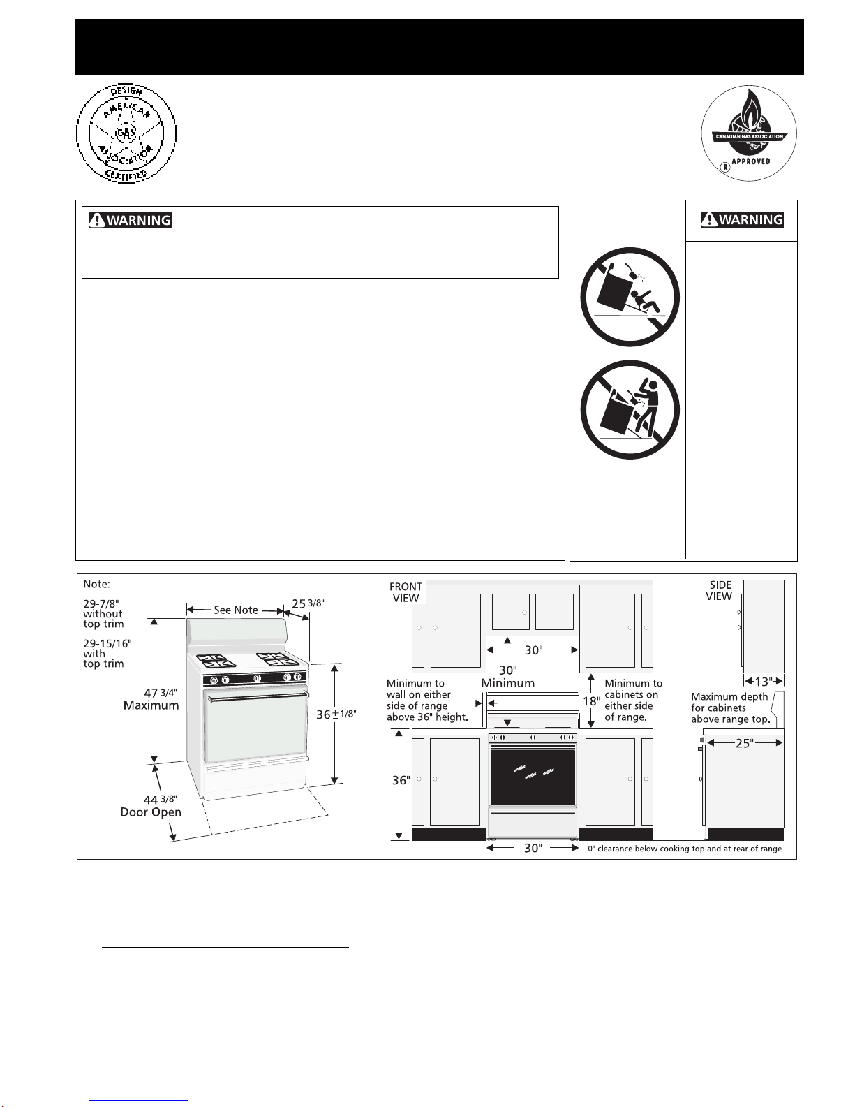
Clearances and Dimensions
1. Location—Check location where the range will be installed. Check for proper electrical and gas supply, and the stability
of the floor.
2. Dimensions that are shown must be used. Given dimensions provide minimum clearance. Contact surface must be solid
and level.
P/N 316002989 (9510)
3"
2"
English—Pages 1-8
Français—Pages 9-16
1
Español—Pages 17-24
Page 2
30" GAS RANGE INSTALLATION INSTRUCTIONS
(For Models with 4 Standard Sealed Top Burners)
Important Notes to the Installer
1. Read all instructions contained in these installation
instructions before installing range.
2. Remove all packing material from the oven
compartments before connecting the gas and electrical
supply to the range.
3. Observe all governing codes and ordinances.
4. Be sure to leave these instructions with the consumer.
Important Note to the Consumer
1. Keep these instructions with your owner's guide for
future reference.
IMPORTANT SAFETY
INSTRUCTIONS
Installation of this range must conform with local codes
or, in the absence of local codes, with the National Fuel
Gas Code ANSI Z223.1—latest edition when installed in
the United States. When installed in Canada, installation
must conform with CAN/CGA-B149.1 and CAN/CGAB149.2.
This range has been design certified by the American
Gas Association and the Canadian Gas Association. As
with any appliance using gas and generating heat, there
are certain safety precautions you should follow. You
will find them in the Owner's Guide, read it carefully.
• Be sure your range is installed and grounded
properly by a qualified installer or service
technician.
• This range must be electrically grounded in
accordance with local codes or, in their absence,
with the National Electrical Code ANSI/NFPA
No .70—latest edition when installed in the
United States. When installed in Canada, this range
must be electrically grounded in accordance with CSA
Standard C22.1, Canadian Electrical Code, Part 1. See
Grounding Instructions on page 5.
• Before installing the range in an area covered
with linoleum or any other synthetic floor
covering, make sure the floor covering can
withstand heat at least 90°F above room
temperature without shrinking, warping or
discoloring. Do not install the range over carpeting
unless you place an insulating pad or sheet of 1/4-inch
thick plywood between the range and carpeting.
• Make sure the wall coverings around the range
can withstand the heat generated by the range.
• Do not obstruct the flow of combustion air at
the oven vent nor around the base or beneath
the lower front panel of the range. Avoid touching
the vent openings or nearby surfaces as they may
become hot while the oven is in operation. This range
requires fresh air for proper burner combustion.
Never leave children alone or
unattended in the area where an appliance is in
use. As children grow, teach them the proper, safe use
of all appliances. Never leave the oven door open when
the range is unattended.
Stepping, leaning or sitting on the
doors or drawers of this range can result in serious
injuries and can also cause damage to the range.
• Do not store items of interest to children in the
cabinets above the range. Children could be
seriously burned climbing on the range to reach items.
• To eliminate the need to reach over the surface
burners, cabinet storage space above the burners
should be avoided.
• Adjust surface burner flame size so it does not
extend beyond the edge of the cooking utensil.
Excessive flame is hazardous.
• Do not use the oven as a storage space. This
creates a potentially hazardous situation.
• Never use your range for warming or heating the
room. Prolonged use of the range without adequate
ventilation can be dangerous.
• Do not store or use gasoline or other flammable
vapors and liquids near this or any other
appliance. Explosions or fires could result.
• Reset all controls to the "off" position after using
a programmable timing operation.
FOR MODELS WITH SELF-CLEAN FEATURE:
• Remove broiler pan, food and other utensils
before self-cleaning the oven. Wipe up excess
spillage. Follow the precleaning instructions in the
Owner's Guide.
• Unlike the standard gas range, THIS COOKTOP IS
NOT REMOVABLE. Do not attempt to remove the
cooktop.
2
Page 3
30" GAS RANGE INSTALLATION INSTRUCTIONS
(For Models with 4 Standard Sealed Top Burners)
DO NOT MAKE ANY ATTEMPT TO
OPERATE THE ELECTRIC IGNITION OVEN DURING AN
ELECTRICAL POWER FAILURE. RESET ALL OVEN
CONTROLS TO "OFF" IN THE EVENT OF A POWER
FAILURE.
The electric ignitor will automatically re-ignite the
oven burner when power resumes if the oven
thermostat control was left in the "ON" position.
When an electrical power failure occurs during use,
the surface burners will continue to operate.
During a power outage, the surface burners can be
lit with a match. Hold a lighted match to the burner,
then slowly turn the knob to the LITE position. Use
extreme caution when lighting burners this way.
Before Starting
Tools You Will Need
For leveling legs:
• Socket wrench (1-3/8" hex) or channel lock pliers
For gas supply connection:
• Pipe wrench
For burner flame adjustment:
• Phillips® head and blade-type screwdrivers
Additional Materials You Will Need
• Gas line shut-off valve
• Pipe joint sealant that resists action of LP/Propane
gas
• Flexible metal appliance conduit (1/2" NPT x 3/4" or
1/2" I.D.) must be AGA/CGA design certified.
Because solid pipe restricts moving the range we
recommend using this flexible conduit (4 to 5 foot
length).
• (2)Flare union adapters (1/2" NPT x 3/4" or 1/2"
I.D.) for connecting flexible appliance conduit.
To convert your range for LP/Propane use, please follow
conversion instructions supplied with the range or
LP/Propane conversion kit now.
DO NOT attempt to convert this range to
LP/Propane settings without the proper LP/Propane
conversion kit provided with the range or obtained from
your dealer.
1. Install Anti-Tip Bracket(s). (See page 8.)
2. Provide an adequate gas supply. This unit is
pre-set to operate on 4" natural gas manifold pressure.
A convertible pressure regulator is connected to the
manifold and MUST be connected in series with the gas
supply line. If the LP/Propane conversion kit has been
used, follow instructions provided with the kit for
converting the pressure regulator to LP/Propane use.
Care must be taken during installation of range not to
obstruct the flow of combustion and ventilation air.
For proper operation, the maximum inlet pressure to the
regulator should be no more than 14 inches of water
column pressure. The inlet pressure to the regulator must
be at least 1 inch greater than regulator manifold
pressure. Examples: If regulator is set for natural gas
4 inch manifold pressure, inlet pressure must be at least
5 inches; if regulator has been converted for LP/Propane
gas 10 inch manifold pressure, inlet pressure must be at
least 11 inches.
The gas supply line should be 1/2" or 3/4" I.D.
Normal Installation Steps
Before Proceeding
Your range has been preset at the factory to operate
on natural gas only. Some models are shipped
convertible with parts and conversion instructions
supplied. Other models have an LP/Propane
Conversion Kit, number 80-8802-10, available
through your dealer.
3
Page 4
30" GAS RANGE INSTALLATION INSTRUCTIONS
(For Models with 4 Standard Sealed Top Burners)
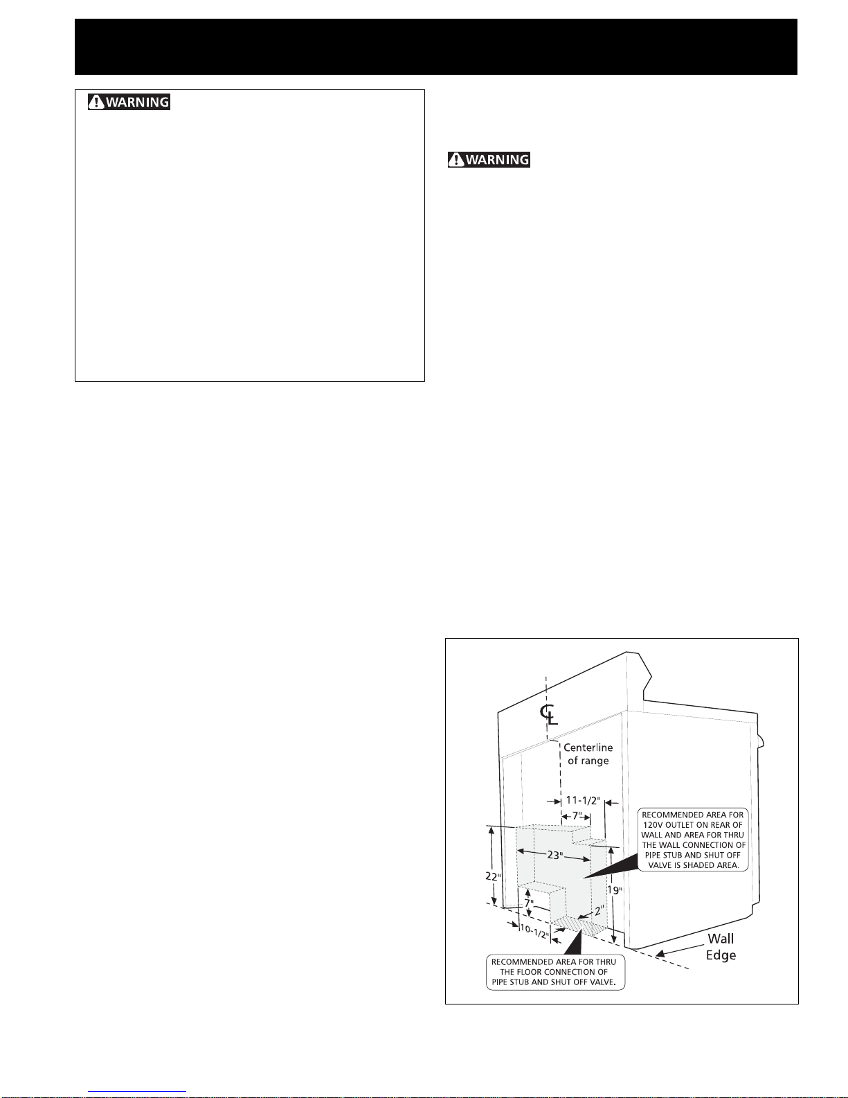
3. Seal the openings. Seal any openings in the wall
behind the range and in the floor under the range
after gas supply line is installed.
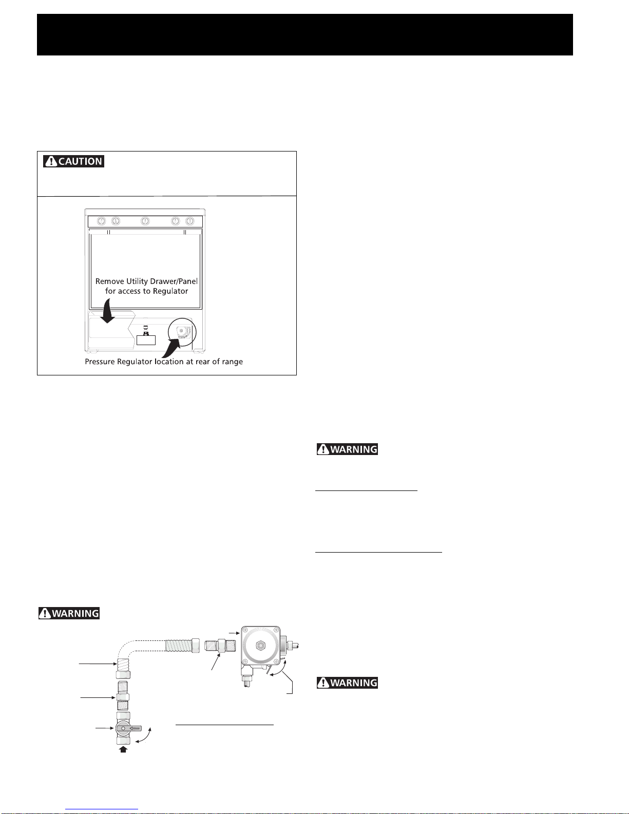
4. Connect the range to the gas supply. To
prevent leaks, put a pipe joint sealant on all male
(outside) pipe threads.
Do not allow regulator to turn on
pipe when tightening fittings. Your regulator is in
one of the two locations shown below.
a) Install an external manual gas shut-off valve to gas
supply line in an easily-accessible location outside of
the range. Be sure you know how and where to
shut-off the gas supply to the range.
b) Install 1/2" flare union adapter to pressure
regulator.
c) Attach appliance conduit to flare union on
regulator.
d) Install flare union adapter to external manual
shut-off valve.
e) Attach appliance conduit to flare union on shut-off
valve.
f) Make sure service shut-off valve on pressure
regulator is in "ON" position.
g) Check for leaks. Turn the gas supply on to the
range and use a liquid leak detector at all joints and
conduits to check for leaks in the system.
Do not use a flame to check for gas leaks.
Pressure Regulator
Flexible
Appliance
Conduit
Flare
Union
Adaptor
External Manual
Shutoff Valve
Gas Supply
On
Off
Flare Union
Adaptor
Service Shut-Off Valve
Electric Ignition models
only.
Be sure lever is in the
"On" position when
installation is complete.
Off
On
Checking Manifold Gas Pressure
Disconnect the range and its individual shut-off valve
from the gas supply piping system during any pressure
testing of that system at test pressures greater than 14"
of water column pressure (approximately 1/2" psig).
The appliance must be isolated from the gas supply
piping system by closing its individual manual shut-off
valve during any pressure testing of the gas supply
piping system at test pressures equal to or less than 14"
of water column pressure (approximately 1/2" psig).
If it should be necessary to check the manifold gas
pressure, connect manometer (water gauge) or other
pressure device to the top burner right rear orifice.
Using a rubber hose with inside diameter of
approximately 1/4," hold tubing down tight over orifice.
Turn burner valve on.
For an accurate pressure check have at least two (2)
other top burners burning. Be sure the gas supply (inlet)
pressure is at least one inch above specified range
manifold pressure. The gas supply pressure should never
be over 14" water column. When properly adjusted for
Natural Gas the manifold pressure is 4." (For LP/Propane
Gas the manifold pressure is 10.")
5. Read electrical connection details below
and connect electricity to range.
Before servicing, disconnect electrical
supply at circuit breaker, fuse or power cord.
Electric Requirements: An individual, properly grounded
and polarized branch circuit protected by a 15 amp.
circuit breaker or time delay fuse. See serial plate for
proper voltage.
Extension Cord Precautions: Because of potential safety
hazards under certain conditions, we strongly
recommend against the use of any extension cord.
However, if you still elect to use an extension cord, it is
absolutely necessary that it be a UL listed 3-wire
grounding type appliance extension cord and that the
current carrying rating of the cord in amperes be
equivalent to or greater than the branch circuit rating.
Such extension cords are obtainable through your local
service organization.
PLEASE READ CAREFULLY! For personal
safety, this product must be properly grounded.
4
Page 5
30" GAS RANGE INSTALLATION INSTRUCTIONS
(For Models with 4 Standard Sealed Top Burners)
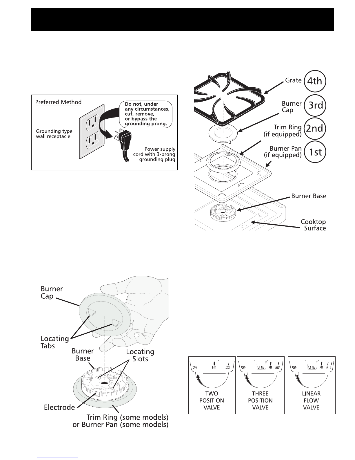
Grounding Instructions
The power cord of this appliance is equipped with a
3-prong (grounding) plug which mates with a standard
3-prong grounding wall receptacle to minimize the
possibility of electric shock hazard from this appliance.
The customer should have the wall receptacle and circuit
checked by a qualified electrician to make sure the
receptacle is properly grounded and polarized.
Where a standard two-prong wall receptacle is
encountered, it is the personal responsibility and
obligation of the customer to have it replaced with a
properly grounded three-prong wall receptacle.
6. Installation of Burner Cap Assembly
Your range may be equipped with either trim rings or
burner pans, or trim rings and burner pans. Install pans
(some models) and trim rings (some models) as follows:
DO NOT, UNDER ANY CIRCUMSTANCES, CUT OR
REMOVE THE THIRD (GROUND) PRONG FROM THE
POWER CORD.
Operation of Surface Burners
This range is equipped with one of the burner types
shown below.
Connecteur
souple de
l’appareil
7. Electric Ignition Surface Burners
Operation of electric igniters should be checked after
range and supply line connectors have been carefully
checked for leaks and range has been connected to
electric power. To check for proper lighting, push in and
turn a surface burner knob to the LITE position. You will
hear the igniter sparking. The surface burner should light
when gas is available to the top burner. Each burner
should light within four (4) seconds in normal operation
after air has been purged from supply lines. Visually
check that burner has lit. Once the burner lights, the
control knob should be rotated out of the LITE position.
There are separate ignition devices for each burner. Try
each knob separately until all burner valves have been
checked.
Note: Knob styles may vary from those pictured above.
5
Page 6
30" GAS RANGE INSTALLATION INSTRUCTIONS
(For Models with 4 Standard Sealed Top Burners)
8. Adjust the "LOW" Setting of Surface
Burner Valve (Three Position and Linear
Flow Valves only):
a) Turn control to LITE until burner ignites.
b) Quickly turn knob to LOWEST POSITION.
c) If burner goes out, readjust valve as follows:
Reset control to OFF. Remove the surface burner control
knob, insert a thin-bladed screw driver into the hollow
valve stem and engage the slotted screw inside. Flame
size can be increased or decreased with the turn of the
screw. Adjust flame until you can quickly turn knob from
LITE to LOWEST POSITION without extinguishing the
flame. Flame should be as small as possible without
going out.
After removing all packing materials and literature from
the oven:
a) Set oven to BAKE at 300ºF. See Owner's Guide for
operating instructions.
b) Within 60 seconds the oven burner should ignite.
Check for proper flame, and allow the burner to
cycle once. Reset controls to off.
c) If your model is equipped with a waist-high broiler,
set oven to BROIL. See Owner's Guide for operating
instructions.
d) Within 60 seconds the broil burner should ignite.
Check for proper flame. Reset controls to off.
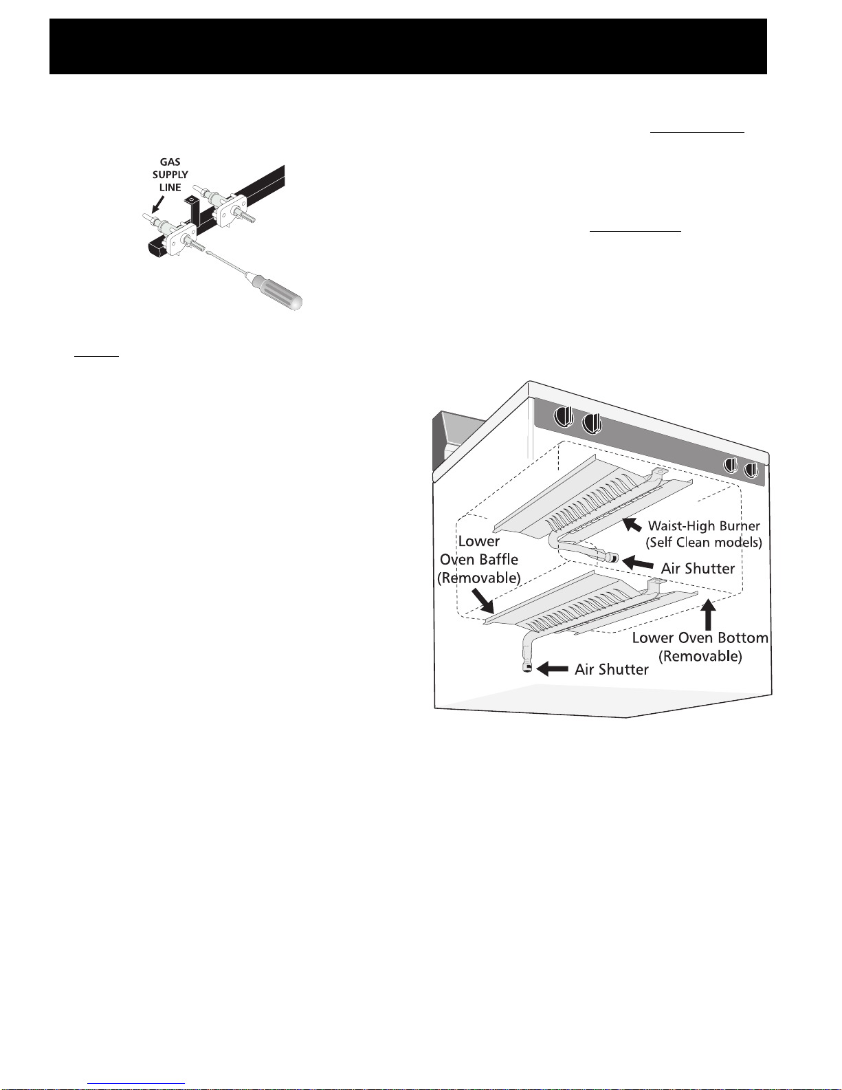
10. Air Shutter-Oven Burner
The approximate flame length of the oven burner is
1 inch (distinct inner, blue flame).
Note: Air mixture adjustment is not required on surface
burners.
Operation of Oven Burners and
Oven Adjustments
9. Electric Ignition Burners
Operation of electric igniters should be checked after
range and supply line connectors have been carefully
checked for leaks and range has been connected to
electric power.
The oven burner is equipped with an electric control
system as well as an electric oven burner igniter. If your
model is equipped with a waist-high broil burner, it will
also have an electric burner igniter. These control
systems require no adjustment. When the oven is set to
operate, current will flow to the igniter. It will "glow"
similar to a light bulb. When the igniter has reached a
temperature sufficient to ignite gas, the electrically
controlled oven valve will open and flame will appear at
the oven burner. There is a time lapse from 30 to 60
seconds after the thermostat is turned ON before the
flame appears at the oven burner. When the oven
reaches the dial setting, the glowing igniter will go off.
The burner flame will go "out" in 20 to 30 seconds after
the igniter goes "OFF." To maintain any given oven
temperature, this cycle will continue as long as the dial
(or display) is set to operate.
To determine if the oven burner flame is proper, remove
the oven bottom and burner baffle and set the oven to
bake at 300°F.
To remove the oven bottom, remove oven hold down
screws at rear of oven bottom. Pull up at rear, disengage
front of oven bottom from oven front frame, and pull the
oven bottom out of the oven. Remove burner baffle so
that the burner flame can be observe.
6
Page 7
30" GAS RANGE INSTALLATION INSTRUCTIONS
(For Models with 4 Standard Sealed Top Burners)
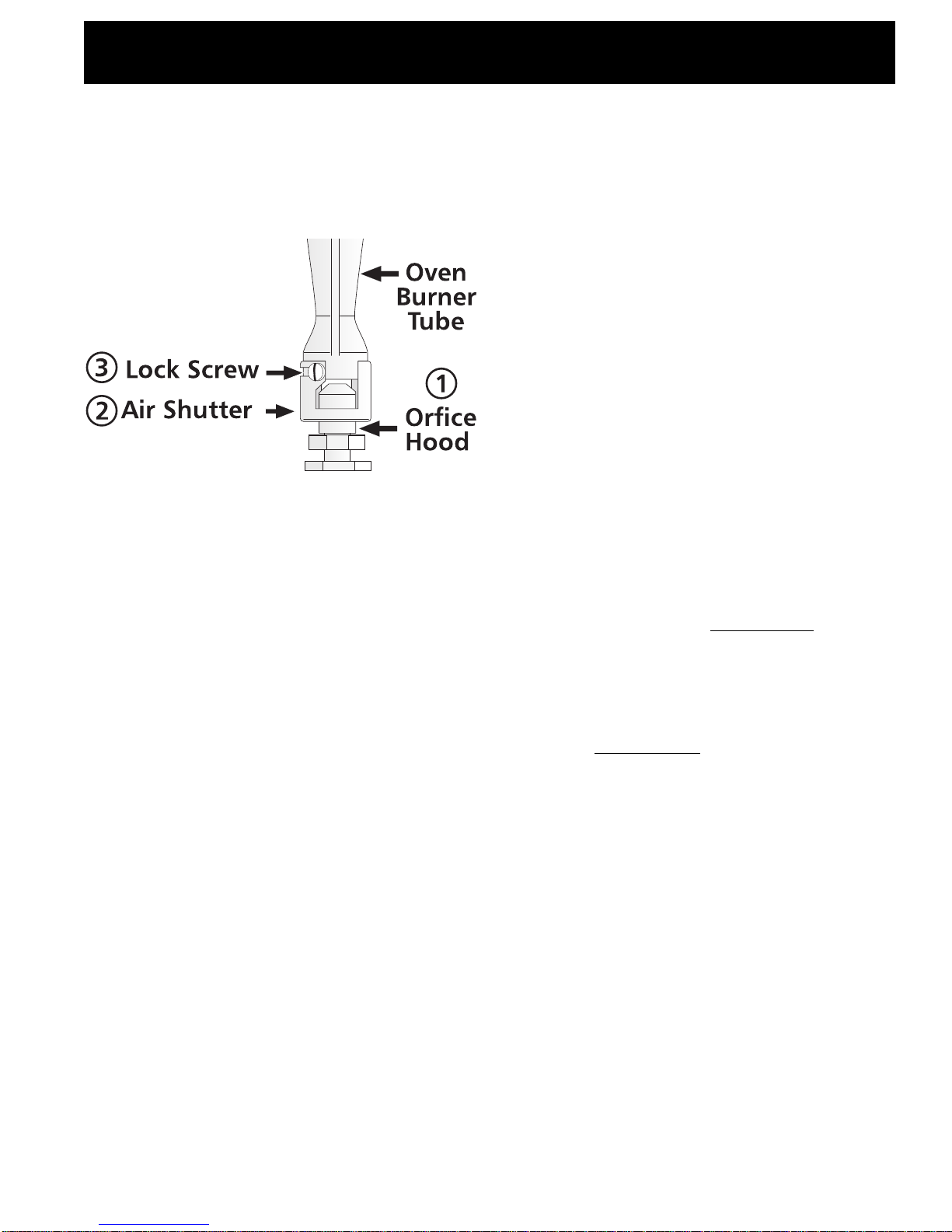
If the flame is yellow in color, increase air shutter
opening size. (See "2" in illustration below.) If the flame
is a distinct blue, reduce the air shutter opening size.
To adjust loosen lock screw (see "3" illustration below),
reposition air shutter, and tighten lock screw. Replace
oven bottom.
11. Air Shutter-Broil Burner (if equipped)
The approximate flame length of the broil burner is
1 inch (distinct inner, blue flame).
To determine if the broil burner flame is proper, set the
oven to broil.
If the flame is yellow in color, increase air shutter
opening size. (See "2" in illustration above.) If the flame
is a distinct blue, reduce the air shutter opening size.
Model and Serial Number
Location
For porcelain enamel ovens, the serial plate is located
on the right-hand surface of the oven front frame in the
broiler or storage drawer area.
For continuous clean ovens, the serial plate is located on
the right front edge of the floor shield located in the
broiler compartment.
When ordering parts for or making inquires about your
range, always be sure to include the model and serial
numbers and a lot number or letter from the serial plate
on your range.
Your serial plate also tells you the rating of the burners,
the type of fuel and the pressure the range was adjusted
for when it left the factory.
Before You Call for Service
Read the Avoid Service Checklist and operating
instructions in your Owner's Guide. It may save you
time and expense. The list includes common
occurrences that are not the result of defective
workmanship or materials in this appliance.
Refer to the warranty in your Owner's Guide for our
toll-free service number and address. Please call or write
if you have inquiries about your range product and/or
need to order parts.
To adjust, loosen lock screw (see "3" in illustration
above), reposition air shutter, and tighten lock screw.
12. Make Sure Range is Level.
Level the range by placing a level horizontally on an
oven rack. Check diagonally from front to back, then
level the range by either adjusting the leveling legs or by
placing shims under the corners of the range as needed.
13. After installation is complete, make
sure all controls are left in the OFF
position.
Care, Cleaning and Maintenance
Refer to the Owner's Guide for operating and cleaning
instructions.
If moving the range is necessary for cleaning or
maintenance, shut off gas supply. Disconnect the gas
and electrical supply. If the gas or electrical supply is
inaccessible, lift the unit slightly at the front and pull out
away from the wall. Pull only as far as necessary to
disconnect the gas and electrical supply. Finish removing
the unit for servicing and cleaning. Reinstall in reverse
order making sure to level the range and check gas
connections for leaks. See page 8, paragraph 5 for
proper anchoring instructions.
7
Page 8
30" GAS RANGE INSTALLATION INSTRUCTIONS
(For Models with 4 Standard Sealed Top Burners)
Anti-Tip Brackets Installation
Instructions
Important Safety Warning
To reduce the risk of tipping of the range, the range
must be secured to the floor by properly installed anti-tip
brackets and screws packed with the range. Failure to
install the anti-tip brackets will allow the range to tip
over if excessive weight is placed on an open door or if a
child climbs upon it. Serious injury might result from
spilled hot liquids or from the range itself.
Follow the instructions below to install the anti-tip
brackets.
If range is ever moved to a different location, the anti-tip
brackets must also be moved and installed with the
range. To check for proper installation, see step 5.
Tools Required:
5/16" Nutdriver or Flat Head Screwdriver
Adjustable Wrench
Electric Drill
3/16" Diameter Drill Bit
3/16" Diameter Masonry Drill Bit (if installing in concrete)
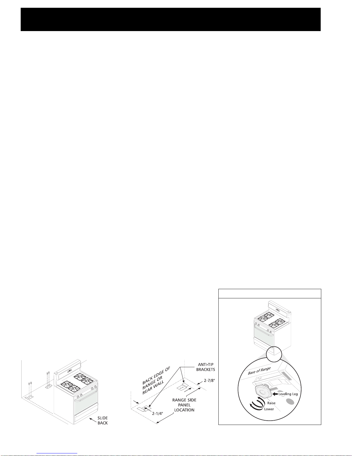
Anti-Tip Brackets Installation Instructions
Brackets attach to the floor at the back of the range to
hold both rear leg levelers. When fastening to the floor,
be sure that screws do not penetrate electrical wiring or
plumbing. The screws provided will work in either wood
or concrete. The anti-tip brackets are attached to the
back of the range.
1. Unfold paper template and place it flat on the floor
with the back and side edges positioned exactly
where the back and sides of range will be located
when installed. (Use the diagram below to locate
brackets if template is not available.)
2. Mark on the floor the location of the 4 mounting
holes shown on the template. For easier installation,
3/16" diameter pilot holes 1/2" deep can be drilled
into the floor.
3. Remove template and place brackets on floor with
turned up flange to the front. Line up holes in
brackets with marks on floor and attach with 4
screws provided. Brackets must be secured to solid
floor. If attaching to concrete floor, first drill 3/16"
dia. pilot holes using a masonry drill bit.
4. Level range if necessary, by adjusting 4 leg levelers
with wrench. (See Figure 1 below.) A minimum
clearance of 1/8" is required between the bottom of
the range and the rear leg levelers to allow room for
the anti-tip brackets.
5. Slide range into place making sure rear legs are
trapped by ends of brackets. Range may need to be
shifted slightly to one side as it is being pushed back
to allow rear legs to align with brackets. Remove
lower panel, storage drawer or open broiler
compartment to inspect brackets. You may also
grasp the top rear edge of the range and carefully
attempt to tilt it forward to make sure range is
properly anchored.
Two Piece Anti-Tip Bracket
12:00
Figure 1
12:00
8
Page 9

NOTICE D’INSTALLATION DE LA CUISINIÈRE AU GAZ DE 76,2 CM (30 PO)
(Pour les modèles pourvus de brûleurs de surface scellés)
L’INSTALLATION ET LES RÉPARATIONS DOIVENT ÊTRE EFFECTUÉES
PAR UN TECHNICIEN QUALIFIÉ.
IMPORTANT : CONSERVER CETTE NOTICE POUR L’INSPECTEUR
D’INSTALLATIONS ÉLECTRIQUES DE LA LOCALITÉ.
LIRE ET CONSERVER CETTE NOTICE POUR RÉFÉRENCE FUTURE.
Toute dérogation aux directives données
dans cette notice peut entraîner des risques d’incendie,
d’explosion, de dommages matériels, de blessures ou de mort.
POUR VOTRE SÉCURITÉ :
— Ne pas entreposer ni utiliser d’essence ou d’autre vapeurs
ou liquides inflammables à proximité de cette cuisinière
ou de tout autre appareil électroménager.
— QUE FAIRE S’IL Y A UNE ODEUR DE GAZ
• N’allumer aucun appareil électrique.
• Ne toucher aucun commutateur électrique; ne pas utiliser
le téléphone dans l’immeuble.
• Appeler la compagnie de gaz immédiatement en utilisant
le téléphone d’un voisin. Suivre les instructions de la
compagnie de gaz.
• S’il est impossible de joindre la compagnie de gaz, appeler
les pompiers.
— L’installation et les réparations doivent être effectuées par
un technicien qualifié, un agent de service ou la compagnie
de gaz.
· TOUTES LES
CUISINIÈRES
PEUVENT
BASCULER.
· DES
BLESSURES
POURRAIENT
SURVENIR.
· INSTALLER LES
AMARRES QUI
ACCOMPAGNENT LA
CUISINIÈRE.
· SE REPORTER
AUX
DIRECTIVES
D’INSTALLATION
DES
AMARRES.
Remarque :
75,88 cm
(29 7/8 po)
sans la
garniture
du dessus
76,04 cm
(29 15/16 po)
avec la
garniture
du dessus
121,28 cm
(47 3/4 po)
maximum
112,7 cm
(44 3/8 po)
porte ouverte
Voir la remarque
64,45 cm
(25 3/8 po)
91,44 cm ± 0,32 cm
(36 po ± 1/8 po)
Dégagement
minimum entre les
murs latéraux et la
cuisinière au-del
de 91,44 cm (36 po)
de hauteur
VUE
FRONTALE
91,44 cm
(36 po)
VUE
LATÉRALE
76,2 cm
(30 po)
76,2 cm
(30 po)
minimum
à
5,08 cm
(2 po)
76,2 cm (30 po)
45,72 cm
(18 po)
Espace de 0 cm sous la surface de cuisson et derrière la cuisinière.
Dégagement
minimum sous
les armoires
sur les côtés
de la cuisinière
Profondeur
maximum
des armoires
au-dessus de
la cuisinière.
33 cm
(13 po)
63,5 cm
(25 po)
Dégagement et dimensions
1. Emplacement—Vérifier l’espace où la cuisinière doit être installée. S’assurer que l’alimentation en gaz et en électricité
est adéquate et que le plancher est stable.
2. Les dimensions indiquées doivent être respectées. Les dimensions indiquées stipulent le dégagement minimum requis.
Le plancher doit être ferme et au niveau.
No de pièce 316002989 (9510)
English—Pages 1-8
Français—Pages 9-16
9
Español—Pages 17-24
Page 10

NOTICE D’INSTALLATION DE LA CUISINIÈRE AU GAZ DE 76,2 CM (30 PO)
(Pour les modèles pourvus de brûleurs de surface scellés)
Remarques importantes à l’intention de
l’installateur
1. Lire les directives contenues dans cette notice
d’installation avant d’installer la cuisinière.
2. Retirer tout le matériel d’emballage de l’intérieur de la
cuisinière avant de brancher la cuisinière à l’alimentation
en gaz et en électricité.
3. Respecter tous les codes et ordonnances qui s’appliquent.
4. Laisser cette notice d’installation au client.
Remarque importante à l’intention du client
1. Conserver cette notice d’installation avec le Guide de
l’utilisateur pour référence future.
CONSIGNES DE SÉCURITÉ
IMPORTANTES
Cette cuisinière doit être installée conformément aux codes
locaux ou, s’il n’existe pas de codes locaux, à l’édition la plus
récente de la norme ANSI Z223.1 si elle est installée aux ÉtatsUnis. Au Canada, l’installation doit respecter les normes CAN/
CGA-B149.1 et CAN/CGA-B149.2
La conception de cette cuisinière a été agréée par l’American
Gas Association et par l’Association canadienne du gaz.
Comme c’est le cas pour tout appareil qui utilise du gaz naturel
et qui émet de la chaleur, certaines consignes de sécurité
doivent être respectées. Ces consignes sont énoncées dans le
Guide de l’utilisateur; lire ce guide attentivement.
• S’assurer que la cuisinière est correctement installée
et mise à la terre par un installateur ou un technicien
qualifié.
• Cette cuisinière doit être mise à la terre conformément
aux codes locaux ou, s’il n’existe pas de codes locaux,
à l’édition la plus récente de la norme ANSI/NFPA
no .70 si elle est installée aux États-Unis. Au Canada, la
mise à la terre doit respecter la norme CSA C22.1 du Code
de l’électricité du Canada, partie 1. Se reporter aux directives
de mise à la terre à la page 5.
• Avant d’installer la cuisinière dans un endroit
recouvert de linoléum ou de tout autre couvreplancher synthétique, s’assurer que le couvre-plancher
peut supporter une chaleur supérieure d’au moins
32,2°C (90°F) à la température de la pièce sans rétrécir,
se tordre ou changer de couleur. Ne pas installer la
cuisinière sur un tapis à moins de placer un revêtement
isolant en contre-plaqué de 0,64 cm (1/4 po) entre la
cuisinière et le tapis.
• S’assurer que le revêtement des murs qui entourent
la cuisinière peut supporter la chaleur qu’émet cet
appareil.
• Ne pas obstruer la circulation de l’air servant à la
combustion près de la grille d’aération ni autour de la
base ou sous le panneau avant de la cuisinière. Éviter
de toucher aux ouvertures d’aération ou aux surfaces
avoisinantes car elles peuvent devenir très chaudes pendant
le fonctionnement de la cuisinière. Cette cuisinière a besoin
d’air frais pour que la combustion soit adéquate.
Ne jamais laisser des enfants seuls
ou sans surveillance près d’un appareil électroménager
en marche. Dès que les enfants sont assez grands, leur
enseigner l’utilisation correcte et sécuritaire de tous les
appareils électroménagers. Ne jamais laisser la porte du four
ouverte lorsque aucun adulte ne se trouve à proximité.
Ne pas monter, s’appuyer ou
s’asseoir sur les portes ou les tiroirs de cette cuisinière;
cela pourrait entraîner des blessures graves et
endommager la cuisinière.
• Ne pas ranger des articles pouvant attirer des enfants
dans les armoires situées au-dessus de la cuisinière.
Les enfants pourraient se brûler gravement en grimpant sur
la cuisinière pour atteindre ces objets.
• Il est préférable de ne pas utiliser l’espace de
rangement situé au-dessus des brûleurs de surface
pour ne pas avoir à tendre les bras au-dessus de
ceux-ce.
• Ajuster l’intensité de la flamme des brûleurs de surface
de façon à ce qu’elle ne dépasse pas le bord de la
casserole. Les flammes trop vives présentent des dangers.
• Ne pas utiliser la cuisinière comme espace de
rangement. Cela pourrait présenter des dangers.
• Ne jamais utiliser la cuisinière pour réchauffer ou
chauffer la pièce. Il est dangereux d’utiliser la cuisinière
de façon prolongée sans une aération suffisante.
• Ne pas entreposer d’essence ou d’autres vapeurs ou
liquides inflammables à proximité de cet appareil ou
de tout autre appareil électroménager. Cela pourrait
entraîner une explosion ou un incendie.
• Remettre tous les boutons de commande à la position
«off» après avoir utilisé une fonction de la minuterie.
POUR LES MODÈLES AUTONETTOYANTS:
• Retirer la lèchefrite, la nourriture et tout autre
ustensile de cuisson avant de nettoyer la cuisinière.
Essuyer le surplus de saleté. Suivre les directives de
préparation au nettoyage contenues dans le Guide de
l’utilisateur.
• Contrairement à la cuisinière au gaz standard, LA
SURFACE DE CUISSON DE CETTE CUISINIÈRE N’EST PAS
AMOVIBLE. Ne pas tenter de retirer la surface de cuisson.
10
Page 11

NOTICE D’INSTALLATION DE LA CUISINIÈRE AU GAZ DE 76,2 CM (30 PO)
(Pour les modèles pourvus de brûleurs de surface scellés)
NE PAS TENTER DE QUELQUE
FAÇON QUE CE SOIT D’UTILISER LE FOUR À ALLUMAGE
ÉLECTRIQUE PENDANT UNE PANNE D’ÉLECTRICITÉ. EN
CAS DE PANNE D’ÉLECTRICITÉ, REMETTRE TOUTES LES
COMMANDES DU FOUR À LA POSITION «OFF».
Si le thermostat du four restait allumé (position «ON»)
pendant une panne d’électricité, l’allumeur électrique
redémarrerait automatiquement le brûleur du four une fois
la panne rétablie.
Si la panne d’électricité survient après l’allumage de l’un
des brûleurs de surface, ce brûleur continuera de
fonctionner.
Pendant une panne d’électricité, les brûleurs de surface
peuvent être allumés à l’aide d’une allumette. Tenir une
allumette allumée au-dessus du brûleur, puis tourner
lentement le bouton vers la position d’allumage «LITE».
Faire preuve d’une grande prudence en allumant les
brûleurs de cette façon.
Avant l’installation
Outils requis
Pour mettre les pieds au niveau :
• Clé à douille (1 3/8 po hexagonale) ou pinces
multiprise
Pour le branchement du gaz :
• Clé à tuyau
Pour ajuster la flamme du brûleur :
• Tournevis Phillips® et tournevis à pointe plate
Pour convertir la cuisinière au gaz propane, suivre les directives
qui accompagnent la cuisinière ou l’ensemble de conversion
au propane.
NE PAS tenter de convertir cette cuisinière au gaz
propane sans l’ensemble de conversion qui accompagne la cuisinière
ou que l’on peut se procurer auprès d’un fournisseur de pièces.
1. Poser les amarres. (Se reporter à la page 16.)
2. Assurer une alimentation en gaz adéquate. Cet
appareil est conçu pour fonctionner sur une pression de
10,16 cm (4 po) produite par un distributeur de gaz naturel.
Un régulateur de pression ajustable est branché au distributeur;
ce régulateur DOIT être relié en série avec la conduite
d’alimentation en gaz. Si un ensemble de conversion au gaz
propane a été installé, suivre les directives qui accompagnent
l’ensemble en question pour convertir le régulateur de pression
à l’alimentation de gaz propane.
Il faut prendre grand soin pendant l’installation de la cuisinière de ne
pas obstruer la circulation de l’air servant à la combustion et à la
ventilation.
Pour que la cuisinière fonctionne correctement, la pression
d’admission maximum au régulateur ne doit pas dépasser 35,56 cm
(14 po) d’eau. La pression d’admission au régulateur doit être d’au
moins 2,54 cm (1 po) plus élevée que la pression au distributeur.
Par exemple, si le régulateur est réglé de façon à ce que la pression de
gaz naturel soit de 10,16 cm (4 po) au distributeur, la pression
d’admission doit être d’au moins 12,7 cm (5 po). Si le régulateur a
été converti à une alimentation en gaz propane et que la pression au
distributeur est de 25,4 cm (10 po), la pression d’admission doit être
d’au moins 27,94 cm (11 po).
Matériel additionnel requis
• Robinet d’arrêt de la conduite de gaz
• Mastic pour joints de tuyaux qui résiste à l’action
corrosive du propane
• Conduit en métal souple (1,27 cm (1/2 po) NPT sur
1,9 cm (3/4 po) ou 1,27 cm (1/2 po) d.i.) approuvé
AGA/CGA. Puisque les tuyaux rigides restreignent les
déplacements de la cuisinière, il est recommandé
d’utiliser ce conduit souple (1,2 m à 1,5 m de long).
• 2 adaptateurs à évasement (1,27 cm (1/2 po) NPT
sur 1,9 cm (3/4 po) ou 1,27 cm (1/2 po) d.i.) pour
brancher le conduit souple.
Étapes habituelles d’installation
Avant l’installation :
La cuisinière est conçue de façon à ne fonctionner que sur
une alimentation en gaz naturel. Toutefois, certains modèles
sont accompagnés de pièces et d’instructions de conversion.
D'autres modèles comportent un ensemble de conversion
au gaz propane no 80-8802-10 que vous pouvez vous
procurer auprès d'un détaillant.
La conduite d’alimentation en gaz doit être de 1,27 cm
(1/2 po) ou 1,9 cm (3/4 po) d.i.
Centre de
la cuisinière
17,78 cm
(7 po)
29,21 cm
58,42 cm
(23 po)
55,88 cm
(22 po)
17,78 cm
(7 po)
26,67 cm
(10 1/2 po)
ESPACE RECOMMANDÉ POUR LE
BRANCHEMENT DU TUYAU ET DU
ROBINET D’ARRÊT DANS LE
PLANCHER.
(11 1/2 po)
5,08 cm
(2 po)
48,26 cm
(19 po)
LA ZONE OMBRAGÉE
INDIQUE L’ESPACE
RECOMMANDÉ POUR LA
PRISE DE 120 V SUR LE MUR
ET L’ESPACE POUR LE
BRANCHEMENT DU TUYAU
ET DU ROBINET D’ARRÊT
DANS LE MUR.
Bord du mur
11
Page 12

NOTICE D’INSTALLATION DE LA CUISINIÈRE AU GAZ DE 76,2 CM (30 PO)
(Pour les modèles pourvus de brûleurs de surface scellés)
3. Sceller les ouvertures. Sceller toute ouverture dans
le mur, derrière la cuisinière, et dans le plancher, sous la
cuisinière, une fois la conduite d’alimentation en gaz
installée.
4. Brancher la cuisinière à l’alimentation en
gaz. Pour prévenir les fuites, appliquer un mastic de joint
pour tuyaux sur les filets de tous les raccords mâles (filets
sur l’extérieur).
Ne pas permettre au régulateur de
tourner sur le tuyau pendant le serrement des pièces. Le
régulateur est situé dans l’espace indiqué ci-dessous.
Retirer le tiroir ou le panneau
pour accéder au régulateur
Emplacement du régulateur
de pression sur l’arrière de la
cuisinière
a) Poser un robinet d’arrêt manuel externe sur la conduite
d’alimentation en gaz dans un endroit facile d’accès à
l’extérieur de la cuisinière. S’assurer de savoir comment et
où couper l’alimentation en gaz de la cuisinière.
b) Poser un adaptateur à évasement de 1,27 cm (1/2 po) sur
le régulateur de pression.
c) Fixer le conduit de l’appareil à l’adaptateur à évasement relié
au régulateur.
d) Fixer un autre adaptateur à évasement au robinet d’arrêt
manuel externe.
e) Fixer le conduit de l’appareil à l’adaptateur à évasement relié
au robinet d’arrêt.
f) S’assurer que le robinet d’arrêt du régulateur de pression est
ouvert (position «ON»).
g) Vérifier s’il y a des fuites. Ouvrir l’alimentation en gaz de la
cuisinière et appliquer un détecteur de fuite liquide sur
tous les joints et les raccords de façon à déceler toute
fuite dans la conduite.
Ne pas utiliser une flamme vive pour
détecter les fuites de gaz.
Régulateur de pression
Conduit
souple de
l'appareil
Adaptateur à
évasement
Robinet d’arrêt
manuel externe
Alimentation en gaz
On
Off
Adaptateur à
évasement
Robinet d’arrêt
des modèles à allumage
électrique seulement.
S’assurer que le levier est
ouvert (position «On») une
fois l’installation terminée.
On
Off
Vérifier la pression de gaz du distributeur
Débrancher la cuisinière et son robinet d’arrêt distinct de la
canalisation de gaz pendant toute vérification de pression de
l’alimentation en gaz à des pressions qui dépassent 35,56 cm
(14 po) d’eau (environ 3,45 kPa (1/2 lb/po²)).
L’appareil doit être isolé de la canalisation de gaz par la
fermeture de son robinet d’arrêt manuel pendant toute
vérification de pression de la canalisation de gaz à des pressions
égales ou inférieures à 35,56 cm (14 po) d’eau (environ
3,45 kPa (1/2 lb/po²)).
S’il s’avère nécessaire de vérifier la pression de la canalisation
de gaz, brancher un manomètre (hydromètre) ou un autre
appareil de vérification de pression à l’orifice du brûleur de
surface arrière droit. Tenir un boyau en caoutchouc d’environ
0,6 cm (1/4 po) de diamètre intérieur relié à l’appareil de
vérification bien serré sur l’orifice. Ouvrir le robinet du brûleur.
Pour une vérification de pression fiable, faire fonctionner au
moins deux (2) autres brûleurs de surface pendant la
vérification. S’assurer que la pression d’alimentation en gaz
(pression d’admission) est supérieure d’au moins 2,54 cm
(1 po) à la pression du distributeur. La pression de
l’alimentation en gaz ne doit jamais être supérieure à
35,56 cm (14 po) d’eau. Lorsque la pression du distributeur
est bien ajustée au gaz naturel, elle est de 10,16 cm (4 po).
(Dans le cas du gaz propane, la pression du distributeur est de
25,4 cm (10 po)).
5. Lire les directives relatives au branchement
électrique ci-dessous et brancher la
cuisinière à l’alimentation électrique.
Avant le branchement, couper
l’alimentation électrique à la boîte de fusibles ou de
disjoncteurs ou au cordon d’alimentation.
Installation électrique : Dérivation distincte adéquatement
mise à la terre et polarisée avec disjoncteur ou fusible à
retardement de 15 A. Se reporter à la plaque signalétique pour
la tension recommandée.
Consignes de sécurité relatives aux cordons de rallonge :
En raison des risques que peuvent présenter les cordons de
rallonge dans certaines circonstances, nous recommandons
fortement de ne pas utiliser de cordon de rallonge avec la
cuisinière. Toutefois, si l’on décide tout de même d’utiliser un
cordon de rallonge, celui-ci doit être à 3 conducteurs, agréé
UL, mis à la terre et conçu pour le branchement d’appareils
électroménagers; il doit être en mesure de soutenir une tension
équivalente ou supérieure à l’ampérage de la dérivation. On
peut se procurer ce type de cordon de rallonge auprès de
l’agent de service après-vente agréé le plus proche.
LIRE ATTENTIVEMENT ! Pour votre
sécurité, cet appareil doit être convenablement mis à la terre.
12
Page 13

NOTICE D’INSTALLATION DE LA CUISINIÈRE AU GAZ DE 76,2 CM (30 PO)
(Pour les modèles pourvus de brûleurs de surface scellés)
Mise à la terre
Le cordon d’alimentation électrique de cet appareil est pourvu
d’une fiche à 3 broches (mise à la terre) qui convient aux prise
murales standard à 3 ouvertures mises à la terre, et ce de façon
à minimiser les risques d’électrocution que pourrait présenter
cet appareil. Le consommateur doit faire vérifier la prise murale
et le circuit par un électricien agréé afin de s’assurer que la prise
est correctement mise à la terre et polarisée.
Méthode privilégiée
Il ne faut en aucun cas
couper, retirer ou
contourner la broche
de terre de cette fiche.
Prise murale
mise à la terre
Cordon
d’alimentation
avec fiche à 3
broches mise
à la terre
Lorsque la prise murale n’a que deux ouvertures, il incombe
au propriétaire de l’appareil de faire remplacer cette prise par
une prise à trois ouvertures convenablement mise à la terre.
IL NE FAUT EN AUCUN CAS COUPER OU RETIRER LA
BROCHE DE TERRE DU CORDON D’ALIMENTATION
ÉLECTRIQUE.
Fonctionnement des brûleurs de
surface
Cette cuisinière est pourvue de brûleurs scellés, comme le
montre l’illustration qui suit.
Couvercle du
brûleur
Languettes
de fixation
Base du
brûleur
Ouvertures de
fixation
6. Installation des pièces qui recouvrent le
brûleur
La cuisinière est pourvue d’anneaux de garniture ou de
cuvettes, ou encore de ces deux dispositifs. Installer les cuvettes
(certains modèles) et les anneaux de garniture (certains
modèles) comme suit :
Grille
Couvercle
du brûleur
Anneau de garniture
(certains modèles)
Cuvette du brûleur
(certains modèles)
Base du brûleur
Surface de cuisson
7. Brûleurs de surface à allumage électrique
Le fonctionnement de l’allumage électrique doit être vérifié une
fois que la détection de fuite dans les raccords de la cuisinière
et de la conduite d’alimentation a été effectuée et que la
cuisinière a été branchée à l’alimentation électrique. Pour
vérifier l’allumage, enfoncer et tourner un bouton d’allumage
de brûleur de surface à la position «LITE». On entend une
étincelle dans le dispositif d’allumage. Le brûleur de surface
devrait s’allumer si l’alimentation en gaz est reliée au brûleur.
Dans des conditions normales, chaque brûleur devrait s’allumer
dans les quatre (4) secondes une fois que l’air a été purgé des
conduites d’alimentation. Vérifier visuellement si le brûleur est
allumé. Une fois le brûleur allumé, le bouton de commande
doit être retiré de la position «LITE». Chaque brûleur est pourvu
d’un dispositif d’allumage distinct. Vérifier chacun des boutons
pour tester tous les brûleurs.
Électrode
Anneau de garniture (certains modèles)
ou cuvette du brûleur (certains modèles)
COMMANDE
À DEUX
POSITIONS
COMMANDE À
TROIS
POSITIONS
COMMANDE
À DÉBIT
LINÉAIRE
Remarque : Le style des robinets peut différer des styles
illustrés.
13
Page 14

NOTICE D’INSTALLATION DE LA CUISINIÈRE AU GAZ DE 76,2 CM (30 PO)
(Pour les modèles pourvus de brûleurs de surface scellés)
8. Ajustement du réglage faible «LOW» du
robinet des brûleurs (commandes à débit linéaire
ou à trois positions seulement) :
CONDUITE
D’ALIMENTATION
EN GAZ
a) Tourner le bouton de commande à la position «LITE»
jusqu’à ce que le brûleur s’allume.
b) Tourner rapidement la commande à la POSITION LA PLUS
FAIBLE.
c) Si le brûleur s’éteint, ajuster le robinet de la façon
suivante :
Remettre le bouton de commande à la position «OFF». Retirer
le bouton de commande du brûleur, insérer un tournevis à lame
mince dans la tige creuse du robinet et saisir la vis à filets
interrompus. La taille de la flamme peut être augmentée ou
réduite par le réglage de cette vis. Ajuster la flamme jusqu’à
ce que le bouton de commande puisse être tourné rapidement
de la position «LITE» à la POSITION LA PLUS FAIBLE sans que
la flamme ne s’éteigne. La flamme doit être aussi petite que
possible sans s’éteindre.
Remarque : L’ajustement du mélange d’air n’est pas requis
pour les brûleurs de surface.
Une fois tout le matériel d’emballage et la documentation
sortis du four :
a) Régler le four sur CUISSON «BAKE» à 154°C (300°F). Se
reporter au Guide de l’utilisateur pour les directives de
fonctionnement.
b) Le brûleur du four devrait s’allumer dans les 60 secondes
qui suivent. S’assurer que la flamme est adéquate et
permettre au brûleur d’accomplir un cycle complet.
Refermer les boutons de commande (position «off»).
c) Si la cuisinière est pourvue d’un brûleur de grillage à
hauteur de la taille, régler le four sur GRILLAGE «BROIL».
Se reporter au Guide de l’utilisateur pour les directives de
fonctionnement.
d) Le brûleur de grillage devrait s’allumer dans les
60 secondes qui suivent. S’assurer que la flamme est
adéquate. Refermer les boutons de commande.
10. Obturateur d’air / brûleur du four
La flamme du brûleur du four mesure environ 2,5 cm (1 po)
(flamme intérieure de couleur bleue).
Brûleur à hauteur de
la taille (modèles
autonettoyants)
Déflecteur inférieur
du four (amovible)
Obturateur d’air
Fonctionnement des brûleurs du
four et ajustement du four
9. Brûleurs à allumage électrique
Le fonctionnement de l’allumage électrique doit être vérifié une fois
que la détection de fuite dans les raccords de la cuisinière et de la
conduite d’alimentation a été effectuée et que la cuisinière a été
branchée à l’alimentation électrique.
Le brûleur du four est pourvu d’un dispositif de contrôle électrique
ainsi que d’un dispositif d’allumage électrique. Si la cuisinière est
pourvue d’un brûleur de grillage à hauteur de la taille, ce brûleur
dispose également d’un dispositif d’allumage électrique. Ces
dispositifs de contrôle n’ont pas à être ajustés. Une fois le four prêt à
fonctionner, l’alimentation électrique se rend au dispositif d’allumage.
Ce dispositif «s’illumine» comme une ampoule électrique. Lorsque
le dispositif d’allumage atteint la température requise pour enflammer
le gaz, le robinet à commande électrique du four s’ouvre et la flamme
se forme sur le brûleur. Il faut de 30 à 60 secondes entre le moment
où le thermostat est allumé et l’apparition de la flamme sur le brûleur.
Lorsque le four atteint la température prévue, le dispositif d’allumage
s’éteint. La flamme du brûleur s’éteint dans les 20 à 30 secondes qui
suivent la fermeture du dispositif d’allumage. Pour maintenir une
température donnée dans le four, le cycle se poursuit tant que la
commande (ou le voyant) fonctionne.
Fond du four
(amovible)
Obturateur d’air
Pour déterminer si la flamme du brûleur du four est adéquate,
retirer le fond du four et le déflecteur, puis régler le four sur
CUISSON «BAKE» à 154°C (300°F).
Pour retirer le fond du four, enlever les vis de support situées
sur sa partie arrière. Le soulever par l’arrière, désengager son
devant du cadre avant du four, puis le tirer pour le sortir du
four. Retirer le déflecteur de façon à pouvoir observer la
flamme.
14
Page 15

NOTICE D’INSTALLATION DE LA CUISINIÈRE AU GAZ DE 76,2 CM (30 PO)
(Pour les modèles pourvus de brûleurs de surface scellés)
Si la flamme est de couleur jaune, accroître l’ouverture de
l’obturateur d’air. (Se reporter au numéro 2 de l’illustration
qui suit.) Si la flamme est d’un bleu marqué, réduire l’ouverture
de l’obturateur d’air.
Pour ajuster la flamme, desserrer la vis de blocage (se reporter
au numéro 3 de l’illustration qui suit), ajuster l’obturateur d’air,
puis resserrer la vis de blocage. Remettre le fond du four en
place.
Tuyau du
brûleur
du four
Vis de blocage
Obturateur d’air
Capuchon
de l’orifice
11. Obturateur d’air / brûleur de grillage
(s’il y a lieu)
La flamme du brûleur du four mesure environ 2,5 cm (1 po)
(flamme intérieure de couleur bleue).
Pour déterminer si la flamme du brûleur de grillage est
adéquate, régler le four sur GRILLAGE «BROIL».
Si la flamme est de couleur jaune, accroître l’ouverture de
l’obturateur d’air. (Se reporter au numéro 2 de l’illustration
qui précède.) Si la flamme est d’un bleu marqué, réduire
l’ouverture de l’obturateur d’air.
Pour ajuster la flamme, desserrer la vis de blocage (se reporter
au numéro 3 de l’illustration qui précède), ajuster l’obturateur
d’air, puis resserrer la vis de blocage.
12. S’assurer que la cuisinière est au niveau
Mettre la cuisinière au niveau en plaçant un niveau à
l’horizontale sur une gille du four. Vérifier en diagonale d’avant
en arrière, puis mettre la cuisinière au niveau, soit en ajustant
les pieds de nivellement, soit en plaçant des cales sous les coins
au besoin.
13. Une fois l’installation terminée, s’assurer
que tous les boutons de commande sont
fermés (position «off»).
Emplacement des numéros de
modèle et de série
Dans le cas des fours émaillés, la plaque signalétique est située
sur le bord avant droit du cadre du four, dans le compartiment
du grilloir ou le tiroir de rangement.
Dans le cas des fours à nettoyage continu, la plaque
signalétique est située sur le bord avant droit du protecteur
de plancher situé dans le compartiment du grilloir.
Lorsqu’il faut commander des pièces ou poser des questions
sur la cuisinière, s’assurer de mentionner le numéro de modèle
et le numéro de série ainsi que le numéro de lot ou la lettre qui
figurent sur la plaque signalétique de la cuisinière.
La plaque signalétique indique également le calibre des
brûleurs, le type de carburant à utiliser et la pression préajustée
au moment où la cuisinière a quitté l’usine.
Avant de faire appel à un centre de
service
Lire le Guide de dépannage et les directives d’utilisation qui
figurent dans le Guide de l’utilisateur. Cela peut épargner du
temps et des dépenses inutiles. Le Guide de dépannage décrit
les problèmes courants qui ne sont pas causés par un vice de
fabrication ou de matériaux.
Se reporter à la garantie qui figure dans le Guide de l’utilisateur
pour connaître le numéro sans frais et l’adresse de notre service
à la clientèle. N’hésitez pas à nous appeler ou à nous écrire si
vous avez des questions au sujet de votre cuisinière ou pour
commander des pièces.
Entretien et nettoyage
Se reporter au Guide de l’utilisateur pour les directives de
nettoyage.
S’il faut déplacer la cuisinière pour la nettoyer ou la réparer,
fermer l’alimentation en gaz. Débrancher l’alimentation en
gaz et l’alimentation électrique. Si les sources de gaz et
d’électricité ne sont pas accessibles, soulever légèrement le
devant de la cuisinière et tirer. Tirer juste assez pour être en
mesure de couper l’alimentation en gaz et en électricité.
Poursuivre le déplacement de la cuisinière pour l’entretien ou
le nettoyage. Réinstaller la cuisinière dans l’ordre inverse en
s’assurant qu’elle est au niveau et qu’il n’y a pas de fuite dans
les raccords de la conduite de gaz. Se reporter au
paragraphe 5 de la page 8 pour savoir comment amarrer
correctement la cuisinière.
15
Page 16

NOTICE D’INSTALLATION DE LA CUISINIÈRE AU GAZ DE 76,2 CM (30 PO)
(Pour les modèles pourvus de brûleurs de surface scellés)
Directives d’installation des
amarres
Consigne de sécurité importante
Pour prévenir tout risque de basculement de la cuisinière, cet
appareil doit être fixé correctement au plancher à l’aide des
amarres et des vis qui l’accompagnent. Si les amarres n’étaient
pas installées, la cuisinière pourrait basculer si un poids excessif
était déposé sur la porte du four lorsque celle-ci est ouverte
ou qu’un enfant grimpait sur la porte. Des blessures graves
pourraient alors être causées par le renversement de liquides
chauds ou par la cuisinière elle-même.
Suivre les directives qui suivent pour installer les amarres.
Si la cuisinière doit être déplacée après son installation initiale,
les amarres doivent également être déplacées et réinstallées.
Pour s’assurer que l’installation a été effectuée correctement,
se reporter à l’étape 5.
Outils requis :
Tournevis à douille de 5/16 po ou tournevis à pointe plate
Clé à molette
Perceuse électrique
Foret de 3/16 po de diamètre
Foret à maçonnerie de 3/16 po de diamètre (si les amarres
doivent être installées dans du béton)
Directives d’installation des amarres
Les amarres se fixent au plancher sur l’arrière de la cuisinière de
façon à tenir les deux pieds de nivellement arrière. En attachant
les amarres au plancher, s’assurer que les vis ne percent pas de fil
électrique ni de conduite de plomberie. Les vis fournies
conviennent aussi bien au bois qu’au béton. Les amarres sont
fixées sur l’arrière de la cuisinière.
1. Déplier le gabarit en papier et le placer à plat sur le plancher
en ajustant bien les bords arrière et latéraux du gabarit sur
l’endroit précis où la cuisinière doit être installée. (Utiliser le
diagramme qui figure ci-dessous pour déterminer
l’emplacement des amarres si le gabarit n’est pas disponible.)
2. Tracer sur le plancher l’emplacement des quatre trous de
montage indiqués sur le gabarit. Pour faciliter l’installation,
des trous de guidage de 0,47 cm (3/16 po) de diamètre et
de 1,27 cm (1/2 po) de profondeur peuvent être percés dans
le plancher.
3. Retirer le gabarit et poser les amarres sur le plancher en
tournant les languettes vers le devant. Aligner les trous des
amarres avec les traits sur le plancher, puis attacher les
amarres à l’aide des quatre vis fournies. Les amarres doivent
être fixées à un plancher ferme. Si elles doivent être fixées à
un plancher en béton, percer d’abord des trous de guidage
de 0,47 cm (3/16 po) de diamètre à l’aide d’un foret à
maçonnerie.
4. Mettre la cuisinière au niveau en ajustant au besoin les quatre
pieds de nivellement à l’aide d’une clé. (Se reporter à la figure
1 ci-dessous.) Un espace minimum de 0,32 cm (1/8 po) est
requis entre le fond de la cuisinière et les pieds de nivellement
arrière pour les amarres.
5. Glisser la cuisinière en place en s’assurant que les pieds de
nivellement arrière sont bien immobilisés par l’extrémité des
amarres. Il peut être nécessaire de tourner légèrement la
cuisinière vers la gauche ou la droite en la poussant pour
permettre aux pieds de s’aligner sur les amarres. Retirer le
panneau inférieur ou le tiroir de rangement, ou encore ouvrir
le compartiment du grilloir pour inspecter les amarres. On
peut aussi saisir la partie supérieure de l’arrière de la cuisinière
pour faire basculer légèrement celle-ci vers l’avant de façon
à s’assurer qu’elle est bien ancrée.
Amarres en deux pièces (certains modèles)
12:00
GLISSER VERS
L’ARRIERE
UR
BORD ARRIERE DE
LA CUISINIERE OU M
ARRIÈRE
5,7 cm
(2 1/4 po)
16
AMARRES
7,3 cm
(2 7/8 po)
EMPLACEMENT
DU PANNEAU
LATERAL DE LA
CUISINIERE
Figure 1
12:00
Base de la cuisinière
Pied de
nivellement
Soulever
Abaisser
Page 17

INSTRUCCIONES DE INSTALACION PARA LA ESTUFA DE GAS DE 30"(76,2cm)
(Para modelos con Quemadores Superiores Sellados)
LA INSTALACION Y EL SERVICIO DEBEN SER EFECTUADOS POR
UN INSTALADOR CALIFICADO.
IMPORTANTE: CONSERVE ESTAS INSTRUCCIONES PARA USO DEL
INSPECTOR LOCAL DE ELECTRICIDAD.
LEA Y CONSERVE ESTAS INSTRUCCIONES PARA REFERENCIA
FUTURA.
Si la información contenida en este manual no
es seguida exactamente, puede ocurrir un incendio o
explosión causando daños materiales, lesión personal o la
muerte.
• TODAS LAS
PARA SU SEGURIDAD:
— No almacene ni utilice gasolina u otros vapores y líquidos
inflamables en la proximidad de éste o de cualquier otro
artefacto.
— QUE DEBE HACER SI PERCIBE OLOR A GAS:
• No trate de encender ningún artefacto.
• No toque ningún interruptor eléctrico; no use ningún
teléfono en su edificio.
• Llame a su proveedor de gas desde el teléfono de un
vecino. Siga las instrucciones del proveedor de gas.
• Si no logra comunicarse con su proveedor de gas, llame al
departamento de bomberos.
— La instalación y el servicio de mantenimiento debe
realizarlo un instalador calificado, la agencia de servicios
o el proveedor de gas.
ESTUFAS
PUEDEN
VOLCARSE.
• PUEDEN
RESULTAR
LESIONES
PERSONALES.
• INSTALE EL
DISPOSITIVO
ANTIVUELCO
EMPACADO
CON LA
ESTUFA.
• VEA LAS
INSTRUCCIONES
DE
INSTALACION.
Nota:
29-7/8" (75,88
cm) sin la
moldura
superior
29-15/16"
(76,04 cm) con
la moldura
superior
47 3/4"
121,28 cm
Máximo
44 3/8"
114,17 cm
Puerta abierta
Ver la nota
Espacios libres y dimensiones
1. Ubicación - Examine la ubicación donde va a instalar la estufa. Compruebe que la alimentación eléctrica y de gas sea
adecuada y compruebe la estabilidad del piso.
2. Las dimensiones que se muestran deben ser usadas. Las dimensiones dadas proporcionan el espacio mínimo necesario. La
superficie de contacto debe ser sólida y nivelada.
P/N 316002989 (9510)
25 3/8"
64,45 cm
36
91,44 cm
± 0,32 cm
DELANTERA
Mínimo hasta la pared
en cualquiera de los
lados de la estufa
por encima de
91,44 cm de altura.
+1/8"
91,44 cm
36"
VISTA
17
2"
5,08 cm
76,2 cm
30"
76,2 cm
Mínimo
30" (76,2 cm)
30"
VISTA
LATERAL
Mínimo hasta
los armarios en
18"
45,72 cm
cualquiera de
los lados de la
estufa.
0 cm de espacio debajo de la estufa y en la parte trasera.
Profundidad
máxima para
los armariospor
encima de la
cubierta de la estufa.
33 cm
25"
63,5 cm
13"
English—Pages 1-8
Français—Pages 9-16
Español—Pages 17-24
Page 18

INSTRUCCIONES DE INSTALACION PARA LA ESTUFA DE GAS DE 30"(76,2cm)
(Para modelos con Quemadores Superiores Sellados)
Importantes notas para el instalador
1. Lea todas las instrucciones contenidas en estas instrucciones
para la instalación antes de instalar la estufa.
2. Saque todos los materiales de embalaje de los
compartimientos del horno antes de conectar la
alimentación de gas y electricidad a la estufa.
3. Observe todos los códigos y ordenanzas en vigor.
4. Asegúrese de dejar estas instrucciones al cliente.
Nota importante para el cliente
1. Guarde estas instrucciones con la guía del propietario para
referencia futura.
IMPORTANTES
INSTRUCCIONES DE
SEGURIDAD
La instalación de esta estufa debe estar conforme con los códigos
locales, o si no existen códigos locales, con el National Fuel Gas
Code (Código Nacional para Gases Combustibles), ANSI
Z223.1—la edición más reciente cuando se instala en los Estados
Unidos. Si se instala en Canadá, la instalación debe estar
conforme con CAN/CGA-B149.1 y CAN/CGA-B149.2.
El diseño de esta estufa ha sido certificado por la American Gas
Association (Asociación Norteamericana de Gas) y la Canadian
Gas Association (Asociación Canadiense de Gas). Igual que con
cualquier electrodoméstico que utiliza gas y genera calor, existen
ciertas precauciones de seguridad que deberá seguir. Las
encontrará en la
• Asegúrese de que su estufa sea instalada y puesta a tierra
debidamente por un instalador capacitado o un técnico
de servicio.
• Esta estufa debe ser puesta a tierra de acuerdo con los
códigos locales, o si no existen códigos locales, con el
National Electrical Code (Código Eléctrico Nacional),
ANSI/NFPA Nº 70 — la edición más reciente cuando se
instala en los Estados Unidos. Si se instala en Canadá, esta
estufa debe ser puesta a tierra de acuerdo con la Norma CSA
Standard C22.1, Canadian Electrical Code (Código Eléctrico
Canadiense), Parte 1. Vea las instrucciones para la puesta a
tierra en la página 5.
• Antes de instalar la estufa en un área cubierta con linóleo
o cualquier otro material de recubrimiento sintético para
pisos, asegúrese de que el recubrimiento para pisos
pueda soportar una temperatura de por lo menos 90°F
(32,2°C) por encima de la temperatura ambiente sin
encogerse, doblarse ni cambiar de color. No instale la estufa
encima de un alfombrado a menos que coloque una alfombrilla
o lámina aislante de madera chapada de 1/4 de pulgada (6,3
mm) de espesor entre la estufa y el alfombrado.
• Asegúrese de que el papel tapiz de paredes alrededor
de la estufa pueda soportar el calor generado por la
estufa.
Guía del Propietario. Léalas con atención.
• No obstruya el paso de aire de combustión en la rejilla
de ventilación del horno ni alrededor de la base ni debajo
del panel delantero inferior de la estufa. Evite tocar las
aberturas de ventilación o las superficies cercanas ya que
pueden calentarse cuando el horno esté en funcionamiento.
Esta estufa requiere aire fresco para la combustión adecuada
del quemador.
desatendidos en el área donde un electrodoméstico esté
en funcionamiento. Cuando los niños crezcan, enséñeles el
uso correcto y seguro de todos los electrodomésticos. No deje
nunca la puerta del horno abierta cuando la estufa esté
desatendida.
puertas o cajones de esta estufa puede provocar lesiones
de consideración y también puede dañar la estufa.
• No almacene artículos de interés para los niños dentro
de los armarios situados por encima de la estufa. Los niños
que se suban a la estufa para alcanzar artículos podrían resultar
gravemente quemados..
• Para eliminar la necesidad de colocarse sobre los
quemadores de la superficie, deben evitarse los armarios
por encima de los quemadores.
• Ajuste el tamaño de la llama del quemador de superficie
para que no sobrepase el borde del utensilio de cocina.
Las llamas excesivas son peligrosas.
• No use el horno para almacenar cosas. Esto crea una
situación peligrosa potencial.
• No use nunca su estufa para mantener un cuarto caliente
ni para calentarlo. El uso prolongado de la estufa sin
ventilación adecuada puede ser peligroso.
• No guarde ni utilice gasolina ni otros vapores y líquidos
inflamables en las cercanías de este o cualquier otro
electrodoméstico. Pueden ocurrir incendios o explosiones.
• Vuelva a colocar todos los controles en la posición de
“off” (apagado) después de haber utilizado una
operación con el programador.
PARA MODELOS CON LA CARACTERISTICA DE
AUTOLIMPIEZA:
• Saque la bandeja del asador, los alimentos y cualquier
otro utensilio antes de poner en marcha la autolimpieza.
Limpie el exceso de derrames de comida. Siga las instrucciones
para la limpieza previa en la
• A diferencia de las estufas a gas communes, LA
TAPA DE LA ESTUFA NO ES REMOVIBLE. No trate de sacar
la tapa.
No deje nunca a los niños solos o
Subirse, apoyarse o sentarse sobre las
Guía del Propietario.
18
Page 19

INSTRUCCIONES DE INSTALACION PARA LA ESTUFA DE GAS DE 30"(76,2cm)
(Para modelos con Quemadores Superiores Sellados)
NO TRATE DE UTILIZAR EL ENCENDIDO
ELECTRICO DURANTE UNA FALLA DEL SUMINISTRO
ELECTRICO. COLOQUE TODOS LOS CONTROLES DEL
HORNO EN “OFF” (APAGADO) EN CASO DE UNA FALLA
ELECTRICA.
El encendedor eléctrico volverá a encender
automáticamente el quemador del horno cuando regrese
el suministro eléctrico si el control del termostato del
horno se dejó en la posición de “ON” (encendido).
Cuando ocurra una falla eléctrica durante el uso, los
quemadores de superficie continuarán funcionando.
Durante una falla eléctrica, los quemadores de superficie
pueden ser encendidos con una cerilla. Sujete una cerilla
encendida justo al lado del quemador y gire despacio la
perilla a la posición de LITE (encendido). Tenga
muchísimo cuidado cuando encienda los quemadores de
esta manera.
Antes de Comenzar
Herramientas necesarias
Para las patas niveladoras:
•
Herramienta para insertar casquillos (1-3/8" hex) o alicates
channel lock
Para la conexión de la alimentación de gas:
• Llave para tuberías
Para el ajuste de la llama del quemador:
•
Destornilladores Phillips® y plano
No trate de convertir esta estufa para ser
usada con propano líquido sin el juego de conversión provisto
con la estufa o el provisto por el distribuidor.
1. Instale el(los) soporte(s) antivuelco. (Vea la
página 24).
2. Provea un suministro de gas apropiado. Esta
unidad ha sido ajustada para operar con un múltiple de
admisión para gas natural de 4". Un regulador de presión
convertible esta conectado a la válvula distribuidora y
DEBE ser conectado en serie con la tubería de sumibistro
de gas. Si el juego de conversión a propano líquido ha sido
usado, siga las instrucciones provistas con el juego para
convertir el regulador de presión para uso con propano
líquido.
Se debe tener cuidado durante la instalación de la estufa para
no obstruir el flujo de combustión y la ventilación.
Para la operación apropiada, la máxima presión de entrada
al regulador no debe exceder la presión de una columna de
agua de 14 pulgadas. La presión de entrada al regulador
debe ser por lo menos 1 pulgada más grande que la válvula
distribuidora. Ejemplos: Si el regulador ha sido ajustado para gas
natural a 4 pulgadas de presión para la válvula distribuidora, la
presión de entrada debe ser por lo menos de propano 5 pulgadas;
si el regulador ha sido convertido a propano líquido a 10
pulgadas de presión para la válvula distribuidora, la presión de
entrada debe ser por lo menos de 11 pulgadas.
La tubería de suministro de gas debe ser de 1/2" o 3/4" D.I.
Materiales adicionales necesarios
• Válvula de cierre de la línea de gas.
• Sellador de juntas para tuberías que resista la acción del
propano líquido.
• Tubo conducto de metal flexible (1/2" NPT x 3/4" o
1/2" D.I.). Debe ser de diseño certificado AGA/CGA. Debido
a que la tubería rígida impide el movimiento de la estufa,
nosotros recomendamos el uso del conducto flexible (4 a 5
pies de longitud).
• (2)adaptadores para gas (1/2" NPT x 3/4" o 1/2" D.I.)
para conectar la estufa al conducto flexible.
Pasos Normales Para la Instalación
Antes de proceder
Su estufa ha sido ajustada para operar con gas natural
solamente. Algunos modelos son convertibles y vienen
equipados con las instrucciones y las partes necesarias para
efectuar la conversión. Otros modelos tienen un Equipo para
Conversión a LP/Propano, número 80-8802-10, disponible a
través de su distribuidor.
Para convertir su estufa para ser usada con propano
líquido, siga las instrucciones provistas con la estufa o
con el juego de conversión.
Línea central
de la estufa
AREA RECOMENDADA PARA PASAR LA
TUBERIA DE CONEXION A TRAVES DEL
PISO PARA LA VALVULA DE CIERRE.
AREA RECOMENDADA PARA EL
TOMACORRIENTE DE 120V EN
LA PARED DE ATRAS Y AREA
PARA PASAR LA TUBERIA DE
CONEXION A TRAVES DE LA
PARED Y PARA LA VALVULA DE
CIERRE, ES EL AREA EN
SOMBRA.
Borde de
la pared
19
Page 20

INSTRUCCIONES DE INSTALACION PARA LA ESTUFA DE GAS DE 30"(76,2cm)
(Para modelos con Quemadores Superiores Sellados)
3. Selle las aberturas. Selle cualquier abertura en la
pared detrás de la estufa y en el piso debajo de la estufa
una vez que haya instalado la línea de alimentación de
gas.
4. Conecte la estufa a la alimentación de gas.
Para evitar fugas, ponga un sellador para juntas de tuberías
en todas las roscas macho (exteriores) de la tubería.
El regulador se encuentra en una de las dos ubicaciones que se
muestran a continuación.
No permita que el regulador gire sobre
la tubería cuando apriete los conectores. El regulador está
ubicado en el área mostrada más a bajo.
Saque el cajón/panel
para tener acceso
al regulador.
Verificación de la Presión de Gas en la Válvula Distribuidora
Desconecte la estufa y su válvula individual de cierre de la
tubería de suministro de gas durante toda prueba de presión del
sistema, con presiones más altas que 14" de columna de agua
(aproximadamente 1/2" lb./pulg.
2
).
El artefacto debe estar aislado de la tubería de suministro
de gas, lo cual se obtendrá cerrando la válvula individual de
cierre manual, durante toda prueba de presión de suministro del
sistema de gas, a presiones de prueba iguales o menores
que 14" de presión de columna de agua (aproximadamente
1/2" lb./pulg.
2
).
Si fuera necesario verificar la presión de gas de la válvula
distribuidora, conecte un manómetro (calibre de agua) u otro
dispositivo de presión al orificio trasero derecho del quemador
superior. Usando una manguera de goma con un diámetro
interior de aproximadamente 1/4", sostenga el tubo
apretadamente sobre el orificio. Coloque la válvula del quemador
en la posición "ON" (ABIERTA).
Para un control correcto de la presión, tenga dos quemadores
superiores encendidos. Asegúrese de que la presión de
suministro de gas (entrada) sea de por lo menos una pulgada
más alta que la presión especificada para la válvula distribuidora
de la estufa. La presión de suministro de gas no debe ser
nunca más alta que 14" por columna de agua. Cuando está
correctamente ajusta da para gas natural, la presión de la válvula
distribuidora es de 4". (Para propana líquido, la presión es 10".)
Ubicación del regulador de presión en la parte de
astrás de la estufa
a) Instale una válvula manual externa para el cierre del gas en
la tubería de suministro de gas, en un lugar que tenga fácil
acceso fuera de la estufa. Esté seguro de saber como y
cuando cerrar el suministro de gas a la estufa.
b) Instale un adaptador para gas de 1/2" al regulador de
presión.
c) Una el conducto flexible para artefactos al adaptador en el
regulador.
d) Instale un adaptador para gas a la válvula manual externa
de cierre.
e) Una el conducto flexible para artefactos al adaptador en la
válvula de cierre.
f) Asegúrese de que la válvula de cierre en el regulador de
presión esté en la posición "ON" (ABIERTA).
g) Controle que no haya pérdidas. Abra el suministro de gas a
la estufa y use un detector líquido de pérrdidas en todas las
juntas y conexiones para controlar que no haya pérdidas en
el sistema.
No use fuego para comprobar si hay fugas
de gas.
Conducto
Flexible
para
Artefactos
Adaptador
de gas
Válvula
Manual
Externa de
Cierre
Suministro de Gas
Regulateur de Presión
Adaptador de gas
Cerrada
Abierta
Abierta
Cerrada
Válvula de Cierre de Servicio.
Modelos con Sistema de
Encendido Eléctrico
Solamente.
Asegúrese de que la palanca
este en la posición abierta
cuando haya terminado la
instalación.
5. Lea más abajo los detalles para la conexión
eléctrica y conecte la electricidad a la estufa.
Antes de de reparar, desconecte el
suministro de corriente del disyuntor, fusibles o cordón
eléctrico.
Requisitos eléctricos: un circuito individual, que esté
correctamente puesto a tierra y protegido por un fusible de
tiempo diferido de 15 amperios. Vea la placa de serie para el
voltaje apropiado.
Precauciones para Cordones de Extensión: Por razones de
seguridad bajo ciertas condiciones, se recomienda no usar
cordones de extensión. Sin embargo si usted deci-diera usarlos,
es absolutamente necessario que sea un cordón de extensión
trifilar con conexión a tierra aprobado por UL con una capacidad
de conducción equivalente o superior a la del circuito. Estos
cordones de extensión pueden ser obtenidos localmente.
¡POR FAVOR LEA CON ATENCION! Para
seguridad personal, este producto debe ser puesto a tierra en
forma apropiada.
20
Page 21

INSTRUCCIONES DE INSTALACION PARA LA ESTUFA DE GAS DE 30"(76,2cm)
(Para modelos con Quemadores Superiores Sellados)
Instrucciones para la toma de tierra
El cable de este electrodoméstico está equipado con un enchufe
(de toma de tierra) con 3 clavijas que entra perfectamente en un
tomacorrientes estándar de pared para 3 clavijas con toma de
tierra para minimizar la posibilidad de descargas eléctricas
causadas por este electrodoméstico. El cliente deberá pedir a un
electricista capacitado que examine el tomacorrientes y el circuito
para asegurarse de que el tomacorrientes esté debidamente
conectado a tierra y polarizado.
Método Preferido
Tomacorriente
de pared con
conexión a tierra
Si sólo se dispone de un tomacorrientes de pared estándar para
dos clavijas, el cliente tendrá la responsabilidad y la obligación
de reemplazarlo con un tomacorrientes de pared para tres clavijas
con puesta a tierra.
NO CORTE NI SAQUE BAJO NINGUNA CIRCUNSTANCIA LA
TERCERA CLAVIJA (DE TOMA DE TIERRA) DEL CABLE.
Bajo ninguna circunstancia corte, saque o
ponga en derivación la
espiga de puesta a tierra
de este enchufe.
Cordón eléctrico
con enchufe de tres
espigas para
puesta a tierra.
6. Instalación y Armado de la Tapa del
Quemador
Su estufa puede estar equipada con anillos o platillos del
quemador, o anillos y platillos del quemador. Instale los platillos
(algunos modelos) y los anillos (algunos modelos) de la siguiente
forma:
Rejilla
Tapa del
Quemador
Anillo (algunos
modelos)
Platillo del
Quemador
(algunos
modelos)
Base del
Quemador
Funcionamiento de los
Quemadores Superiores
Esta estufa esta equipada con quemadores sellados como se
muestra más abajo.
Tapa del
Quemador
Lengüetas
de Posición
Base del
Quemador
Electrodo
Anillo (algunos
modelos)
Platillo del Quemador (algunos modelos)
Ranuras de
Posición
Tapa de la
estufa
7. Encendedor Eléctrico de los Quemadores
Superiores
El funcionamiento de los encendedores eléctricos debe ser
controlado después que la estufa y los conectores a la tubería
de suministro de gas hayan sido controlados por pérdidas y la
estufa haya sido conectada eléctricamente. Para controlar que
el encendido sea correcto, empuje y gire la perilla del quemador
superior hasta la posición "LITE" (ENCENDER). Se podrá oír el
encendedor haciendo chispas. El quemador de superficie se
encenderá cuando el gas llegue al quemador. Cada quemador
se deberá encender en cuatro (4) segundos para un
funcionamiento normal, luego de que el aire haya sido purgado
de la tubería de suministro de gas. Controle visualmente que el
quemador se haya encendido. Luego que el quemador se haya
encendido, la perilla debe ser girada fuera de la posición "LITE"
(ENCENDER). Cada quemador tiene su encendedor individual.
Controle las perillas separadamente hasta que todas las válvulas
hayan sido controladas.
VALVULA
DE DOS
POSICIONES
Nota: El diseño de perillas puede variar con respecto a las
mostradas más arriba.
VALVULA
DE TRES
POSICIONES
VALVULA
DE FLUJO
LINEAL
21
Page 22

INSTRUCCIONES DE INSTALACION PARA LA ESTUFA DE GAS DE 30"(76,2cm)
(Para modelos con Quemadores Superiores Sellados)
8. Ajuste de la regulación “LOW” (Baja) de la
válvula del quemador de superficie
(válvulasde flujo lineal y detres posiciones)
LINEA DE ALIMENTACION
DE GAS
a) Gire la perilla de control a “LITE” (Encendido) hasta que
se encienda el quemador.
b) Gire rápidamente la perilla a “LOWEST POSITION”
(Posición más baja).
c) Si se apaga el quemador, regule de nuevo la válvula de la
manera siguiente:
Coloque el control en OFF (Apagado). Quite la perilla de control
del quemador de superficie e inserte un destornillador de hoja
delgada en el vástago hueco de la válvula hasta que haga
contacto con el tornillo de cabeza ranurada que se encuentra en
el interior. El tamaño de la llama se puede aumentar o disminuir
haciendo girar el tornillo. Regule la llama hasta que se pueda
cambiar rápidamente de LITE (Encendido) a LOWEST POSITION
(Posición más baja) sin que se extinga la llama. La llama debe
quedar lo más pequeña posible pero sin que se apague.
se ponga en “OFF” (Apagado). Para mantener cualquier
temperatura del horno, este ciclo continuará tanto tiempo como
se haya previsto con la perilla (o el display).
Después de haber sacado todos los materiales de embalaje y el
material impreso del horno:
a) Ponga el horno en BAKE (Hornear) a 300° F (148,9° C). Vea
la Guía del Propietario para las instrucciones sobre el
funcionamiento.
b) Dentro de 60 segundos el quemador del horno deberá
encenderse. Compruebe que la llama sea adecuada y deje
que el quemador pase por un ciclo. Vuelva a poner los
controles en “OFF” (Apagado).
c) Si su modelo está equipado con un asador a la altura de la
cintura, ponga el horno en BROIL (Asador). Vea la Guía del
Propietario para las instrucciones sobre el funcionamiento.
d) Dentro de 60 segundos el quemador del horno deberá
encenderse. Compruebe que la llama sea adecuada y deje
que el quemador pase por un ciclo. Vuelva a poner los
controles en “OFF” (Apagado).
10. Obturador de aire-quemador del horno
La longitud aproximada de la llama del quemador del horno es
de 1 pulgada (2,54 cm) (llama claramente azul por dentro).
Nota: El ajuste de la mezcla de aire no es necesario en los
quemadores superiores.
Funcionamiento de los
Quemadores del Horno y Ajustes
del Horno
9. Encendedor Eléctrico de los Quemadores
El funcionamiento de los encendedores eléctricos debe ser
verificado después de comprobar cuidadosamente si la estufa y
los conectores de la tubería de suministro de gas tienen pérdidas
y la estufa haya sido conectada a la energía eléctrica.
El quemador del horno está equipado con un sistema de control
eléctrico así como con un encendedor eléctrico para el quemador
del horno. Si su modelo está equipado con un quemador del
asador a la altura de la cintura, también tendrá un encendedor
eléctrico para el quemador. Estos sistemas de control no
requieren ajustes. Cuando el horno está programado para
funcionar, la corriente pasará al encendedor. “Brillará” como si
fuera una bombilla. Cuando el encendedor haya alcanzado una
temperatura suficiente para encender el gas, la válvula del horno
controlada eléctricamente se abrirá y la llama aparecerá en el
quemador del horno. Hay un intervalo de tiempo de 30 a 60
segundos después de que el termostato sea puesto en ON
(Encendido) antes de que la llama aparezca en el quemador del
horno. Cuando el horno llegue a la graduación de la perilla, el
encendedor brillante se apagará. La llama del quemador se
“apagará” de 20 a 30 segundos después de que el encendedor
Quemador a la altura
de la cintura (modelos
Placa difusora
inferior del horno
(removible)
Obturador del aire
Para determinar si la llama del quemador del horno es adecuada,
quite el fondo del horno y la placa difusora del quemador y ajuste
el horno para hornear a 300° F (148,9° C).
Para quitar el fondo del horno debe quitar los tornillos de sujeción
del horno que están en la parte posterior del fondo del mismo.
Tire de la parte posterior, desaloje la parte delantera del fondo
del horno del bastidor frontal del mismo, y saque directamente el
fondo del horno. Quite la placa difusora del quemador de manera
que se pueda observar la llama del quemador.
autolimpiables)
Obturador del aire
Fondo del horno
inferior (removible)
22
Page 23

INSTRUCCIONES DE INSTALACION PARA LA ESTUFA DE GAS DE 30"(76,2cm)
(Para modelos con Quemadores Superiores Sellados)
Si la llama es de color amarillo, aumente la abertura del obturador
para la mezcla del aire (ver "2" en la ilustración siguiente). Si la
llama es muy azul, disminuya la abertura del obturador del aire.
Para modificar la posición del obturador afloje el tornillo (ver "3"
en la ilustración siguiente), modifique la posición del obturador
y apriete el tornillo. Vuelva a colocar el fondo del horno.
Tubo del
quemador
del horno
Tornillo de cierre
Obturador
del aire
Caperuza
(Tobera)
11. Obturador del aire-quemador del asador
(si está equipado)
La longitud aproximada de la llama del quemador del asador es
de 1 pulgada (2,54 cm) (llama claramente azul por dentro).
Ubicación del Número de Modelo
y de Serie
Para hornos de porcelana esmaltada, la placa con el número de
serie está ubicada en el lado derecho del horno, en el área del
cajón de almacenamiento o el quemador de asar.
Para hornos de limpieza continua, la placa con el número de serie
está ubicada en el borde delantero derecho del protector del piso
en el compartimiento del asador.
Cuando pida piezas o tenga preguntas acerca de su estufa,
asegúrese siempre de incluir los números de modelo y serie y un
número o letra de lote de la placa con el número de serie de su
estufa.
La placa con el número de serie también le indica la capacidad
de los quemadores, el tipo de gas y la presión para la cual fue
ajustada la estufa en la fábrica.
Antes de Llamar al Servicio
Asegúrese de que los fusibles de la casa o los disyuntores para
su estufa no estén fundidos o abiertos. Vea la Lista de Chequeo
para Evitar el Servicio y las instrucciones para el funcionamiento
en la Guía del Propietario. Puede ahorrarle tiempo y dinero. La
lista incluye los problemas comunes que no son el resultado de
una fabricación o materiales defectuosos de este
electrodoméstico.
Para determinar si la llama del quemador del asador es adecuada,
ajuste el horno para asar.
Si la llama tiene un color amarillento, deberá aumentar el tamaño
de la abertura del obturador de aire. (Vea “2” en la ilustración
anterior). Si la llama es de un color claramente azul, debe reducir
el tamaño de la abertura del obturador de aire.
Para ajustar, afloje el tornillo de fijación (vea “3” en la ilustración
anterior), vuelva a colocar el obturador de aire y apriete el tornillo
de fijación.
12. Asegúrese de que la estufa esté nivelada.
Nivele la estufa colocando un nivel horizontalmente sobre una
parrilla del horno. Compruebe diagonalmente de delante hacia
atrás, y luego nivele la estufa ya sea ajustando las patas
niveladoras o colocando calces bajo las esquinas de la estufa
según sea necesario.
13. Una vez que haya terminado la
instalación, asegúrese de que todos los
controles estén colocados en la posición
OFF (Apagada).
Lea la garantía en la
teléfono gratis y la dirección para obtener servicio. Llame o escriba
si tiene preguntas acerca de su estufa y/o necesita pedir piezas.
Guía del Propietario para encontrar nuestro
Cuidado, Limpieza y
Mantenimiento
Lea la Guía del Propietario para ver las instrucciones sobre el
funcionamiento y la limpieza.
Si tiene que sacar la estufa para limpiarla o hacer algún
mantenimiento, corte la alimentación de gas. Desconecte la
alimentación de gas y electricidad. Si la alimentación de gas o
electricidad es inaccesible, levante la estufa ligeramente en la
parte delantera y jale para alejarla de la pared. Jale solamente lo
que sea necesario para desconectar la alimentación de gas y
electricidad. Termine de sacar la estufa para el servicio y la
limpieza. Vuelva a instalarla en el orden inverso asegurándose
de nivelar la estufa y comprobar las conexiones de gas para ver
si hay fugas. Vea la página 24, párrafo 5 para obtener las
instrucciones sobre la fijación correcta.
23
Page 24

INSTRUCCIONES DE INSTALACION PARA LA ESTUFA DE GAS DE 30"(76,2cm)
(Para modelos con Quemadores Superiores Sellados)
Instrucciones de Instalación del
Soporte Antivuelco
Importante Advertencia de Seguridad
Para reducir el riesgo de volcar la estufa, ésta debe ser fijada al
piso por medio de los soportes antivuelco debidamente instalados
y los tornillos que se incluyen con la estufa. El hecho de no instalar
los soportes antivuelco permitirá que la estufa se vuelque si se
pone demasiado peso sobre la puerta abierta o si un niño se sube
a ella. Pueden ocurrir lesiones graves debido a líquidos calientes
que se derramen o debido a la estufa misma.
Siga las instrucciones siguientes para instalar los soportes
antivuelco.
Si alguna vez tiene que mover la estufa a otra ubicación, los soportes
antivuelco deberán ser movidos e instalados también con la estufa.
Para comprobar la instalación correcta, vea el paso 5.
Herramientas necesarias:
Llave para tuercas de 5/16" o destornillador plano
Llave ajustable
Taladro eléctrico
Broca de 3/16" de diámetro
Broca para albañilería de 3/16" de diámetro (si se van a instalar
en hormigón)
Instrucciones de Instalación del Soporte
Antivuelco
Los soportes se fijan al piso en el respaldo de la estufa para sujetar
ambas patas niveladoras traseras. Cuando los fije al piso,
asegúrese de que los tornillos no perforen cableados eléctricos
ni tuberías de plomería. Los tornillos que se incluyen funcionan
tanto con madera como con hormigón. Los soportes antivuelco
están fijados al respaldo de la estufa.
1. Despliegue la plantilla de papel y colóquela plana sobre el
piso con los bordes traseros y laterales colocados
exactamente donde el respaldo y los lados de la estufa
estarán colocados cuando esté instalada. (Use el diagrama
que aparece abajo para ubicar los soportes si no tiene la
plantilla disponible).
2. Marque en el piso la ubicación de los 4 agujeros de montaje
que se ven en la plantilla. Para facilitar la instalación, pueden
taladrarse en el piso agujeros piloto de 3/16" (4,76 mm) de
diámetro y 1/2" (1,27 cm) de profundidad
3. Saque la plantilla y coloque los soportes en el piso con la
pestaña volteada hacia arriba mirando hacia la parte
delantera. Alinee los agujeros de los soportes con las marcas
del piso y fíjelos con los 4 tornillos incluidos. Los soportes
deben estar fijados a un piso sólido. Si se fijan a un piso de
hormigón, taladre primero agujeros piloto de 3/16" (4,76
mm) de diámetro usando una broca para albañilería.
4. Nivele la estufa si es necesario ajustando las 4 patas
niveladoras con la llave. (Vea la Figura 1 abajo). Se requiere
un espacio mínimo de 1/8" (3,17 mm) entre la parte inferior
de la estufa y las patas niveladoras traseras para permitir
espacio para los soportes antivuelco.
5. Empuje la estufa para colocarla en su lugar asegurándose
de que las patas traseras queden prisioneras en los extremos
de los soportes. Puede ser que tenga que mover ligeramente
la estufa hacia un lado a medida que la empuja para permitir
que las patas traseras se alineen con los soportes. Saque el
panel inferior, el cajón y abra el compartimiento del asador
para inspeccionar los soportes. También puede sujetar el
borde superior trasero de la estufa y tratar de volcarla con
cuidado hacia adelante para asegurarse de que esté bien
fijada.
Soporte antivuelco en dos piezas
12:00
EMPUJE HACIA
ATRAS
BORDE TRASERO DE LA
ESTUFA O PARED
TRASERA
UBICACION DEL PANEL
LATERAL
5,71 cm
(2-1/4")
DE LA ESTUFA
24
SOPORTES
ANTIVUELCO
7,3 cm
(2-7/8")
Figura 1
12:00
Base de la estufa
Pata
niveladora
Levante
Baje
 Loading...