

Frigidaire FGEW276SPBB, FGEW276SPFB, FGEW276SPFC Installation Guide
ELECTRIC WALL OVEN INSTALLATION INSTRUCTIONS
(and Optional Electric or Gas Cooktop Combination)
INSTALLATION AND SERVICE MUST BE PERFORMED BY A
QUALIFIED INSTALLER.
United States and
Canada
IMPORTANT: SAVE FOR LOCAL ELECTRICAL INSPECTOR'S USE.
READ AND SAVE THESE INSTRUCTIONS FOR FUTURE REFERENCE.
FORYOURSAFETY:Donotstoreorusegasolineorotherammablevapors
and liquids in the vicinity of this or any other appliance.
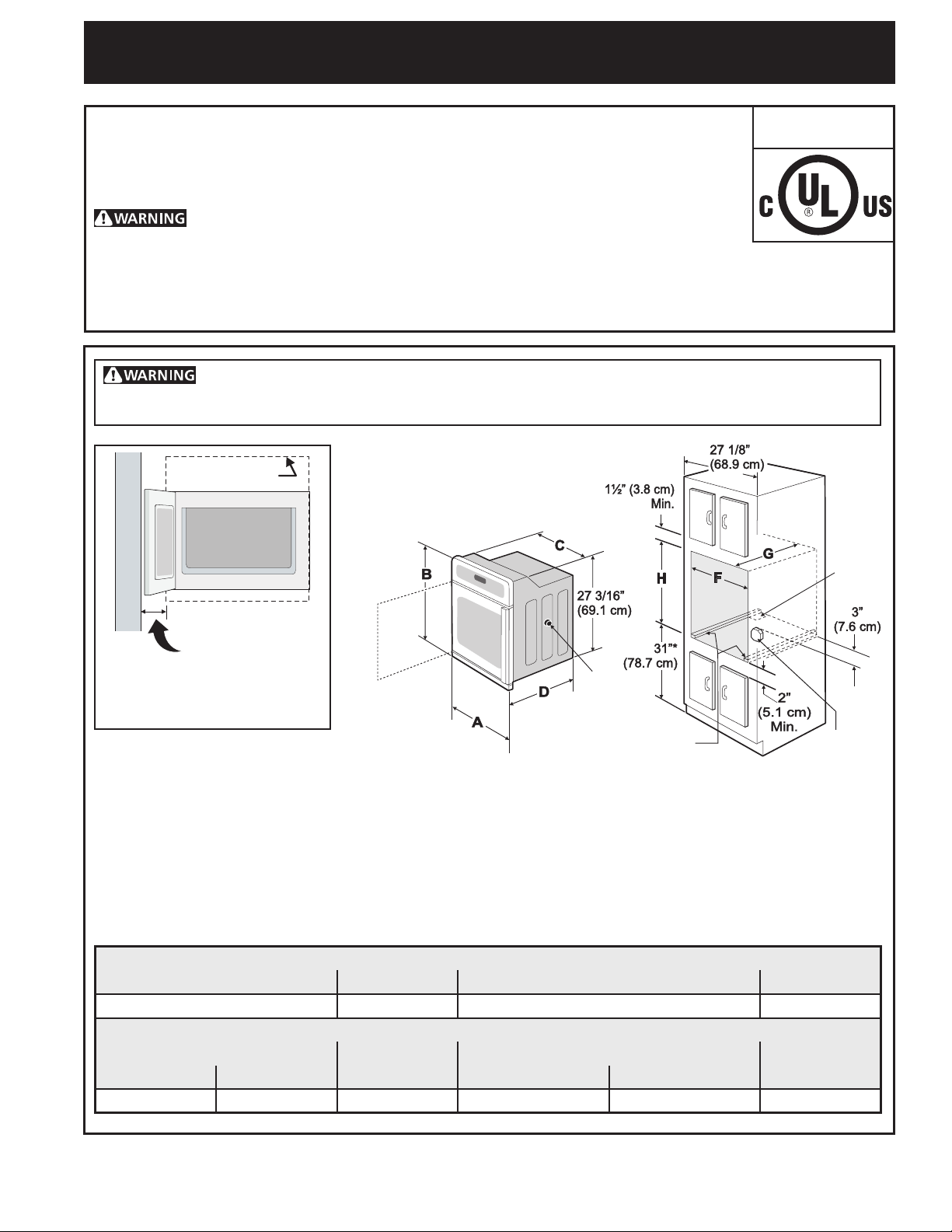
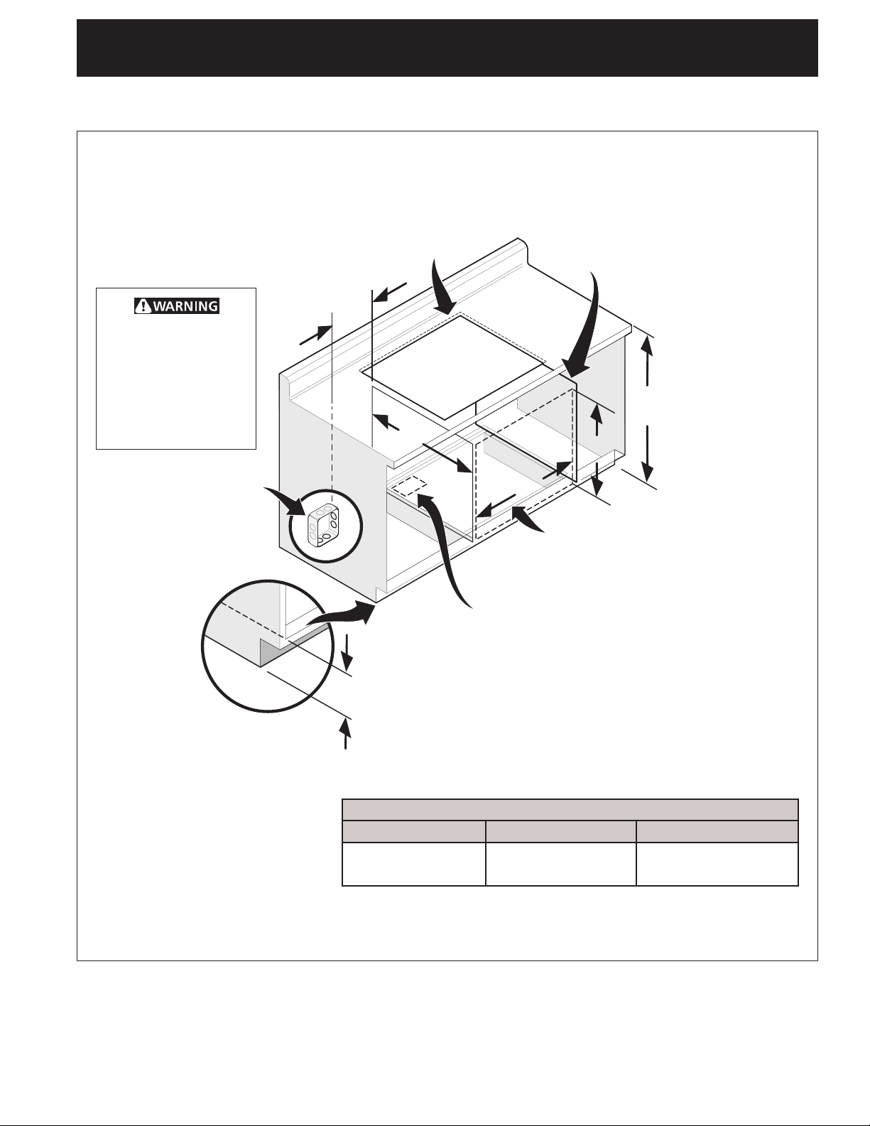
Yournewwallovenhasbeendesignedtotalimitedvarietyofcutoutsizestomakethejob
ofinstallingeasier.Therststepofyourinstallationshouldbetomeasureyourcurrentcutout
dimensions and compare them to the cutout dimensions chart below for your model. You may
ndlittleornocabinetworkbeingnecessary.
Do not remove spacers (if equipped) on the side walls and/or on the back of the built-in
oven. These spacers center the oven in the space provided. The oven must be centered to prevent
excess heat buildup that may result in heat damage or re.
* Suggesteddistancefromoor
Cutout openings
is 31" (78,7 cm).
Minimum required distance is
4 ½" (11,4 cm).
Hole for
Cable
Do not install the
oven closer than the
(seetable)toanyadjoining
cabinetry or walls on the door
hinge side. This will interfere
with oven rack removal.
NOTES:
dimension "I"
Door Open
(see note 2)
Spacer
2" (5 cm) Wide Wood
Spacer if Needed
Figure 1
Electrical
Junction Box
1. Base must be capable of supporting 150 pounds (68 kg).
2. Allow at least 27¼" (69,2 cm) clearance in front of oven for door depth when it is open.
3. Dimension G (cutout depth) is critical to the proper installation of the built-in oven. If the oven decorative trim
does not butt against the cabinet, or if noise is heard on convection models, verify dimension G to assure it is the
required depth.
1
4. For a cutout height greater than 28
/8" (71,4 cm) add one 2" (5 cm) wide wood shim of appropriate height to
each side of the opening under the appliance side rails. For a cutout height (H) greater than 285/8" (72,7 cm)
you can order a larger bottom trim, contact a Service Center
PRODUCT DIMENSIONS
A B C D
27 (68,6) 29 (73,7) 24
5
/8 (62,5) 24¾ (62,9)
CUTOUT DIMENSIONS AND CABINET WIDTH
F
Min. Max. Min. Max.
7
24
/8 (63,2) 25¼ (64,1) 24 (61,0) 27¼ (69,2) 28¼ (71,7) 4½ (11,4)
G (Min.)
H. Standard Height
(Others, see note 4)
I
All dimensions are in inches (cm).
Printed in United States
P/N 318206005 (16/05) Rev. B
English – pages 1-10, Español – páginas 11-19, Français -pages 20-28
1
ELECTRIC WALL OVEN INSTALLATION INSTRUCTIONS
(and Optional Electric or Gas Cooktop Combination)
Important Notes to the Installer
1. Read all instructions contained in these installation
instructions before installing the wall oven.
2. Remove all packing material from the oven
compartments before connecting the electrical
supply to the wall oven.
3. Observe all governing codes and ordinances.
4. Be sure to leave these instructions with the
consumer.
5. THESE OVENS ARE NOT APPROVED FOR
STACKABLE OR SIDE-BY-SIDE INSTALLATION.
Important Note to the Consumer
Keep these instructions with your Owner's Guide for the
local electrical inspector's use and future reference.
IMPORTANT SAFETY
INSTRUCTIONS
• Be sure your wall oven is installed and grounded
properly by a qualied installer or service
technician.
• This wall oven must be electrically grounded in
accordance with local codes or, in their absence,
with the National Electrical Code ANSI/NFPA
No.70- latest edition in United Sates, or with CSA
Standard C22.1, Canadian Electrical Code, Part 1,
in Canada.
Stepping, leaning or sitting on the
door of this wall oven can result in serious injuries
and can also cause damage to the wall oven.
• Never use your wall oven for warming or heating
the room. Prolonged use of the wall oven without
adequate ventilation can be dangerous.
The electrical power to the oven must
be shut off while line connections are being made.
Failure to do so could result in serious injury or
death.
1. Carpentry
Refertogure1forthedimensionsofyourappliance,
and the space necessary to receive the oven. The
oven support surface may be solid plywood or similar
material, however the surface must be level from side
to side and from front to rear.
2. Adjusting Oven Height
Ovenheightcanbeadjustedwith2"(5cm)widewood
shimswhenneededtotintoanexistingcabinet
cutout opening, when cutout height exceeds 28
(71,4 cm) (Figure 1). Place shims of appropriate height
beneath the oven side rails. For a cutout height greater
than 28¼" (71,7 cm) you can order a larger bottom
trim, contact a Service Center
1
/
"
8
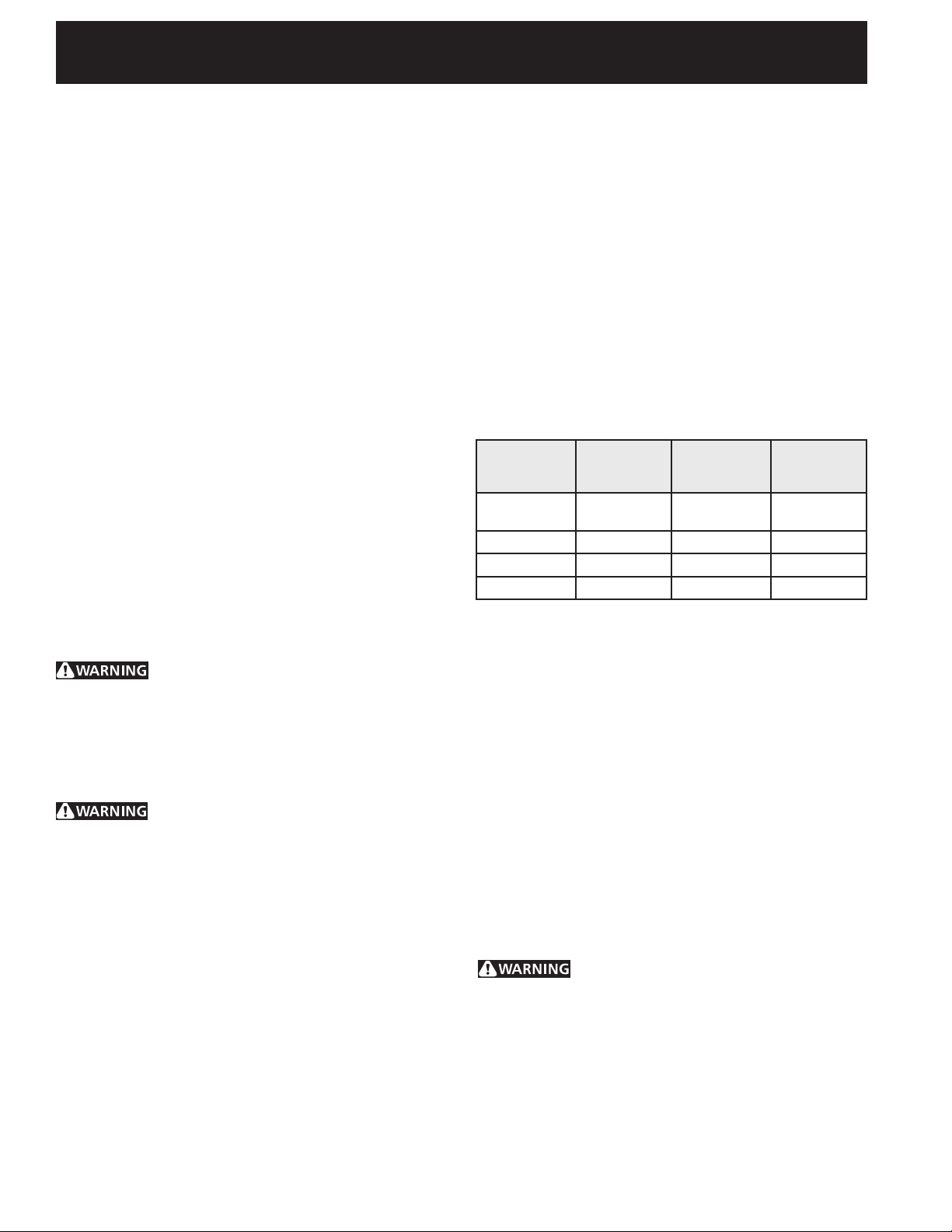
3. Electrical Requirements
This appliance must be supplied with the proper
voltage and frequency, and connected to an individual,
properly grounded branch circuit, protected by a circuit
breaker or fuse. To know the circuit breaker or fuse
requiredbyyourmodel,seetheserialplatetondthe
wattage consumption and refer to table A to get the
circuit breaker or fuse amperage.
Appliance
Rating Watts
240V
Less than
4800W
4800W - 7200W
7200W - 9600W
9600W and +
Observe all governing codes and local ordinances
1. A 3-wire or 4-wire single phase 120/240 or 120/208
Volt,60HzAConlyelectricalsupplyisrequiredona
separate circuit fused on both sides of the line (red
and black wires). A time-delay fuse or circuit breaker is
recommended. DO NOT fuse neutral (white wire). Only
certain cooktop models may be installed over certain
built-in electric oven models. Approved cooktops and
built-in ovens are listed by the MFG ID number (see
the insert sheet included in the literature package).
NOTE:Wiresizesandconnectionsmustconformwith
thefusesizeandratingoftheapplianceinaccordance
with the American National Electrical Code ANSI/NFPA
No. 70-latest edition, or with Canadian CSA Standard
C22.1, Canadian Electrical Code, Part 1, and local
codes and ordinances.
with this appliance. Such use may result in a re,
electrical shock, or other personal injury.
Protection
Circuit
Recommended
20A
30A
40A
50A
Table A
An extension cord should not be used
Appliance
Rating Watts
208V
Less than
4100W
4100W - 6200W
6200W - 8300W
8300W and +
Protection
Circuit
Recommended
20A
30A
40A
50A
2. These appliances should be connected to the
fused disconnect (or circuit breaker) box through
exiblearmoredornonmetallicsheathedcable.
Theexiblearmoredcableextendingfromthe
appliance should be connected directly to the
junctionbox.Thejunctionboxshouldbelocated
2
ELECTRIC WALL OVEN INSTALLATION INSTRUCTIONS
(and Optional Electric or Gas Cooktop Combination)
as shown in Figure 1 and with as much slack as
possible remaining in the cable between the box
and the appliance, so it can be moved if servicing
is ever necessary.
3. A suitable strain relief must be provided to attach
theexiblearmoredcabletothejunctionbox.
Electrical Shock Hazard
• Electrical ground is required on this
appliance.
• Do not connect to the electrical supply until
appliance is permanently grounded.
• Disconnect power to the junction box before
making the electrical connection.
• This appliance must be connected to a
grounded, metallic, permanent wiring
system, or a grounding connector should be
connected to the grounding terminal or wire
lead on the appliance.
• Do not use a gas supply line for grounding
the appliance.
Failure to do any of the above could result in a
re, personal injury or electrical shock.
In cold weather shipping and storage
conditions,makesurethatovenisinnallocation
at least three (3) hours before switching on power.
Switching on power while oven is still cold may
damage the oven controls.
4. Electrical connection
It is the responsibility and obligation of the consumer to
contactaqualiedinstallertoassurethattheelectrical
installation is adequate and is in conformance with
the National Electrical Code ANSI/NFPA No. 70latest edition, or with CSA Standard C22.1, Canadian
Electrical Code, Part 1, and local codes and
ordinances.
Risk of electrical shock (Failure to
heed this warning may result in electrocution or
other serious injury.) This appliance is equipped
with copper lead wire. If connection is made to
aluminum house wiring, use only connectors that
are approved for joining copper and aluminum wire
in accordance with the National Electrical Code
and local code and ordinances. When installing
connectors having screws which bear directly on
the steel and/or aluminum exible conduit, do no
tighten screws sufciently to damage the exible
conduit. Do not over bend or excessively distort
exible conduit to avoid separation of convolutions
en exposure of internal wires.
DO NOT ground to a gas supply pipe. DO NOT
connect to electrical power supply until appliance
is permanently grounded. Connect the ground wire
before turning on the power.
(If your appliance is equipped with a
white neutral conductor.)
This appliance is manufactured with a white neutral
power supply and a frame connected copper
wire. The frame is grounded by connection of
grounding lead to neutral lead at the termination
of the conduit, if used in USA, in a new branch
circuit installation (1996 NEC), mobile home,
recreational vehicles, where local code do not
permit grounding trough the neutral (white) wire
or in Canada, disconnect the white and green lead
from each other and use ground lead to ground
unit in accordance with local codes, connect
neutral lead to branch circuit-neutral conductor
in usual manner see Figure 3. If your appliance
is to be connected to a 3 wire grounded junction
box (US only), where local code permit connecting
the appliance-grounding conductor to the neutral
(white) see Figure 2.
NOTE TO ELECTRICIAN: The armored cable leads
suppliedwiththeapplianceareUL-recognizedfor
connection to larger gauge household wiring. The
insulation of the leads is rated at temperatures much
higher than temperature rating of household wiring.
The current carrying capacity of the conductor is
governed by the temperature rating of the insulation
around the wire, rather than the wire gauge alone.
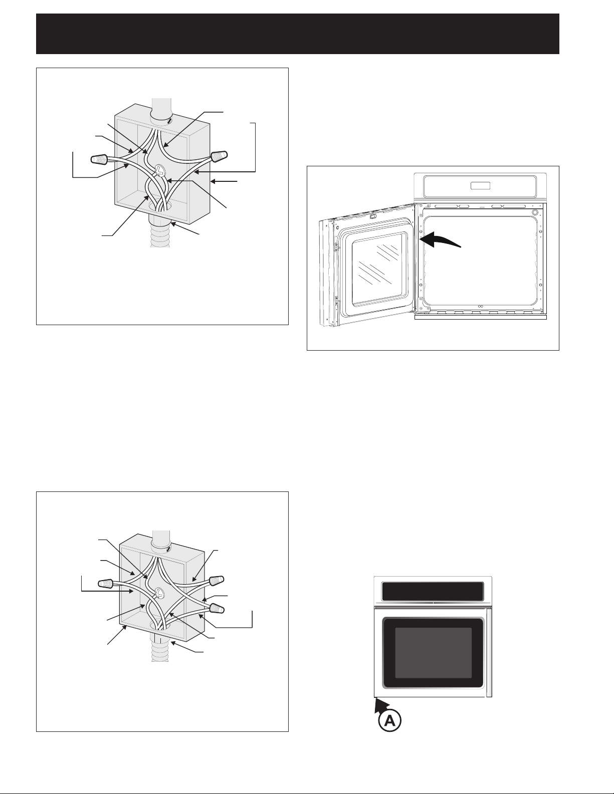
Where local codes permit connecting the
appliance-grounding conductor to the neutral
(white) wire (US Only) (see gure 2):
1. Disconnect the power supply.
2. Inthejunctionbox:
connect appliance and power supply cable wires as
shown in Figure 2.
3
ELECTRIC WALL OVEN INSTALLATION INSTRUCTIONS
Cable from Power Supply
White Wire
(Neutral)
Red
Wires
Ground Wire
(Bare or Green Wire)
Cable from appliance
3-WIRE GROUNDED JUNCTION BOX
(and Optional Electric or Gas Cooktop Combination)
Figure 2
Black
Wires
Junction
Box
White Wire
(Neutral)
U.L.-Listed Conduit
Connector (or CSA
listed)
5. Model and Serial Number Location
The serial plate is located along the interior side trim of
the oven and visible when the door is opened.
When ordering parts for or making inquires about your
oven, always be sure to include the model and serial
numbers and a lot number or letter from the serial plate
on your oven.
Wall Oven
Serial Plate
Location
If oven is used in a new branch circuit installation
(1996 NEC), mobile home, recreational vehicle,
or where local codes DO NOT permit grounding
through the neutral (white) wire, the appliance
frame MUST NOT be connected to the neutral wire
of the 4-wire electrical system. (see gure 3):
1. Disconnect the power supply.
2. Separate the green (or bare copper) and white
appliance cable wires.
3.Inthejunctionbox:
connect appliance and power supply cable wires as
shown in Figure 3.
Cable from Power Supply
Ground
Wire
Red
Wires
Ground Wire
(Bare or
Green Wire)
Junction
Box
Cable from
appliance
White
Wire
Black
Wires
White Wire
U.L.-Listed
Conduit
Connector (or
CSA listed)
Figure 4
6. Oven Door Opening Reversal
Procedure
Thiswallovencaneasilybemodiedtoaleftoraright
hand opening. When you receive your appliance the
door is set for a left opening. It is preferable to reverse
door opening prior to the installation of the wall oven
into the cabinet cavity. If wall oven is already installed,
removed the anti-tip screws and then pull wall oven
outward by approx. 2” (5 cm).
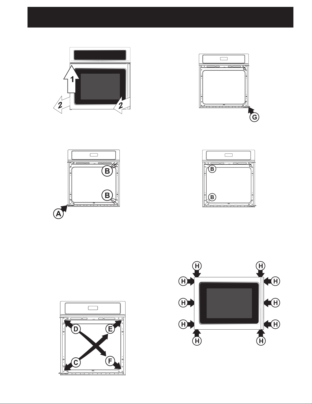
6.1 To remove the oven door from the
appliance
Be sure the oven door is closed.
6.1.1. Unscrew and remove the threaded pin from the
lower hinge (See A, Figure 5).
Figure 3
4-WIRE GROUNDED JUNCTION BOX
Figure 5
4
ELECTRIC WALL OVEN INSTALLATION INSTRUCTIONS
(and Optional Electric or Gas Cooktop Combination)
6.1.2. Support and lift up the door such as to clear the
lower hinge pin (Figure 6).
Figure 6
6.1.3. Remove the oven door from the appliance.
6.1.4. Gently lay the door on a work table handle up.
6.1.5. Reinstall the threaded pin at its initial position
(see A, Figure 7).
6.2.4. Remove the threaded pin from left side lower
hinge (see G, Figure 9). Save the threaded pin for
reassembly later.
Figure 9
6.2.5. Replace the six (6) screws and washers removed
on step 1 on the left side of the oven frame (See
B, Figure 10).
Figure 7
6.2 Oven frame modications
6.2.1. Remove the six (6) screws and washers located
on the right side of the oven frame (see B, Figure
7). Keep the screws and washers to reinstall them
at step 6.2.5.
6.2.2. Remove the lower hinge on the left side of the
oven frame (See C, Figure 8) and install it on the
upper right side of the oven frame (see E, Figure
8).
6.2.3. Remove the upper hinge on the left side of the
oven frame (see D, Figure 8) and relocate it on
the lower right side of the oven frame (see F,
Figure 8).
Figure 10
6.3 Oven door modications:
6.3.1. Removethethree(3)screws,eachside,xing
the outer door assembly (glass panel and
handle). Remove also the four (4) screws located
on top (2) and under (2) outer door assembly (see
H, Figure 11 (10 screws total)).
Figure 11
Figure 8
5
ELECTRIC WALL OVEN INSTALLATION INSTRUCTIONS
(and Optional Electric or Gas Cooktop Combination)
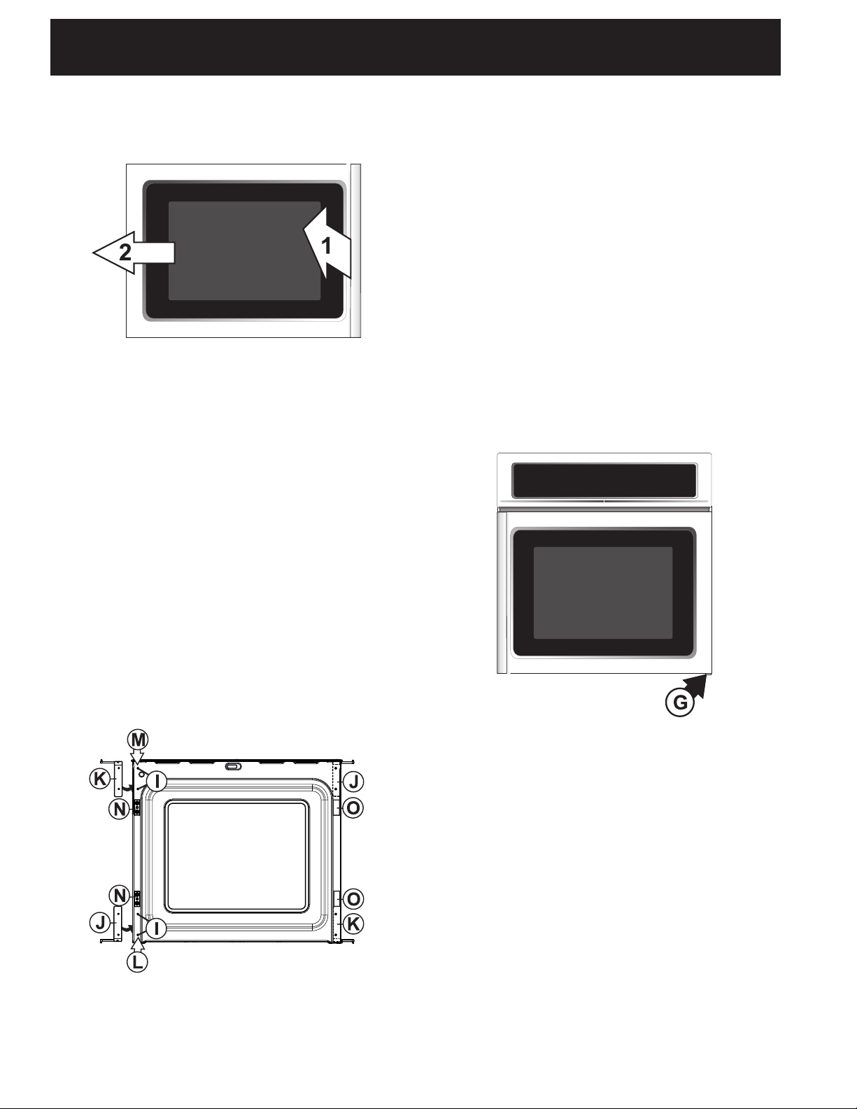
6.3.2. To remove the outer door assembly, lift lightly
the handle side about 30°. Slide the outer door
assembly out of the door hinges (Figure 12).
Figure 12
6.3.3. Lay the outer door assembly on a work table.
6.3.4. Turn the inner door to have the interior of the
oven door faces up.
6.3.5. Remove the four (4) caps (See I, Figure 13)
located on the left side of the inner door. Keep
them for step 6.3.11.
6.3.6. Remove the two (2) plastic plugs (See O, Figure
13) located on the left side of the inner door.
Keep them for step 6.3.8.
6.3.7. Remove the two (2) latch pins (Position N, Figure
13) located on the on the left side and install them
on the right side (Position O, Figure 13).
6.3.8. Relocate the two (2) plastic plugs, removed on
step 6.3.6, on the right of the inner door (Position
N, Figure 13).
6.3.9. Unscrew the right side lower hinge and reinstall it
on the left side upper position (See K, Figure 13).
6.3.10. Do the same with the hinge located on right side
upper position and reinstall it on the left side
lower position (see J, Figure 13).
6.3.11. Replace the four (4) caps removed on step 6.3.5
on the right side of the inner door.
6.3.12. Turn the inner door to have the interior of the
oven door faces on the work table.
6.3.13. Replace the outer door assembly on the inner
door in the inverse manner than step 6.3.2.
6.3.14. Fix the outer door assembly using the ten (10)
screws removed on step 6.3.1 (See H, Figure 11).
6.4 To replace the oven door
6.4.1. Replace the door. First engage the upper door
hinge pin in the oven frame hinge.
6.4.2. Once the upper door hinge is in place, lift up the
oven door such as to clear the lower oven frame
hinge and be able to insert the lower door hinge
pin in the lower oven frame hinge.
6.4.3. Close the door. CAUTION Do not open the door
until the threaded pin is in place.
6.4.4. Fix the threaded pin in the lower hinge (See G,
Figure 14).
Figure 14
Figure 13
6
ELECTRIC WALL OVEN INSTALLATION INSTRUCTIONS
(and Optional Electric or Gas Cooktop Combination)
7. Cabinet Installation
IMPORTANT
Do not lift the oven by the door handle.
Heavy Weight Hazard
• Use 2 or more people to move and install wall oven.
• Failure to follow this instruction can result in injury
or damage to the unit.
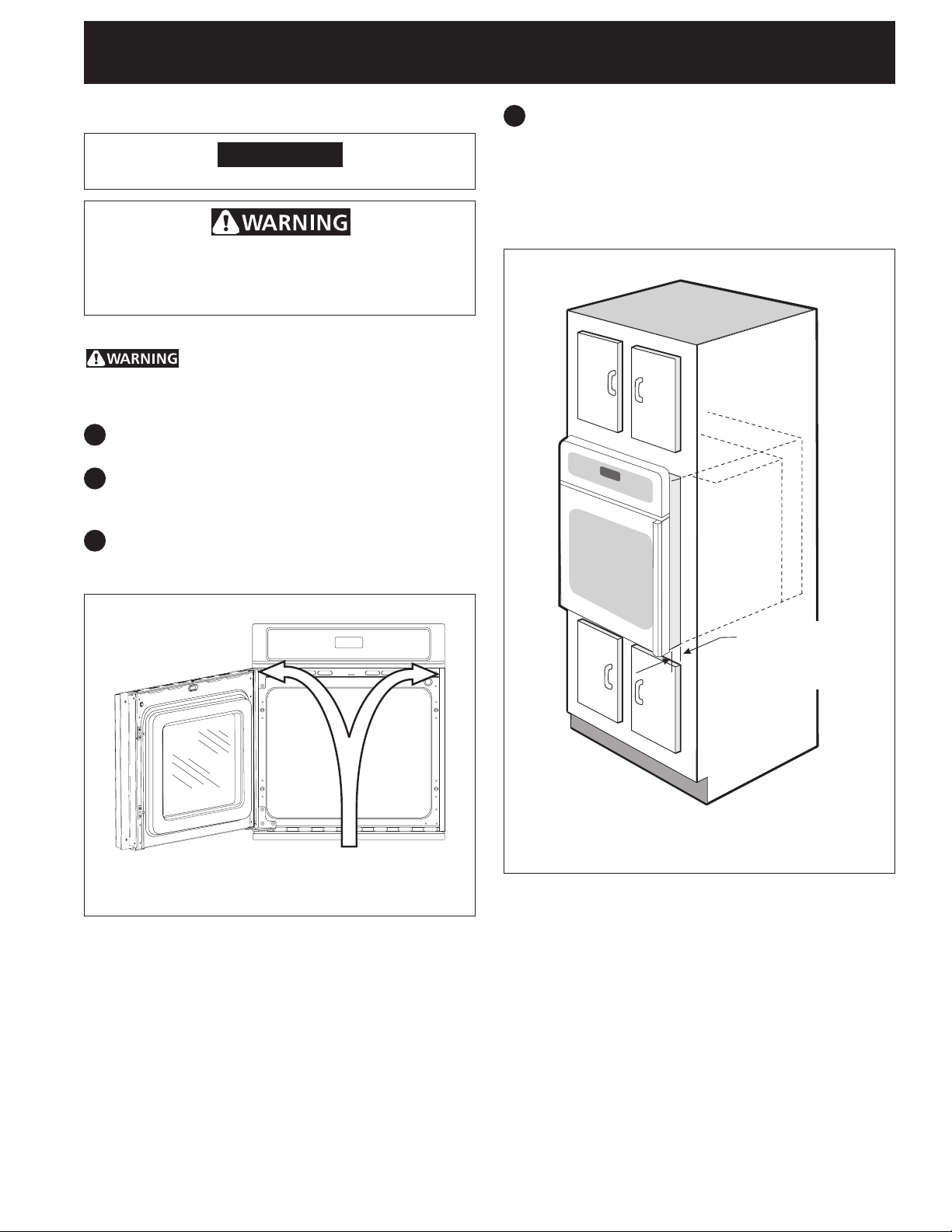
Install the Anti-Tip Mounting Screws:
The wall oven can tip when the door is
open. The anti-tip mounting screws supplied with the
wall oven must be installed to prevent tipping of the
wall oven and injury to persons.
1
Unpack the wall oven. Remove the bottom trim
taped on the oven side panel.
2
The mounting holes in the side trims may be used
as a template to locate the appliance mounting
screwholes(seegure15).
3
Usethetwoscrewssuppliedtoxtheapplianceto
the cabinet.
4
Insert the oven into the cabinet opening. Slide
oven inward leaving 1½" (3,8 cm) clearance
between the oven and front of cabinet (see Figure
16). Pull the armored cable through the hole for it
inthecabinetandtowardthejunctionboxwhile
moving the appliance inward.
Anti-Tip Mounting Holes
Figure 15
1½" (3,8 cm)
clearance
between unit
Figure 16
7
ELECTRIC WALL OVEN INSTALLATION INSTRUCTIONS
(and Optional Electric or Gas Cooktop Combination)
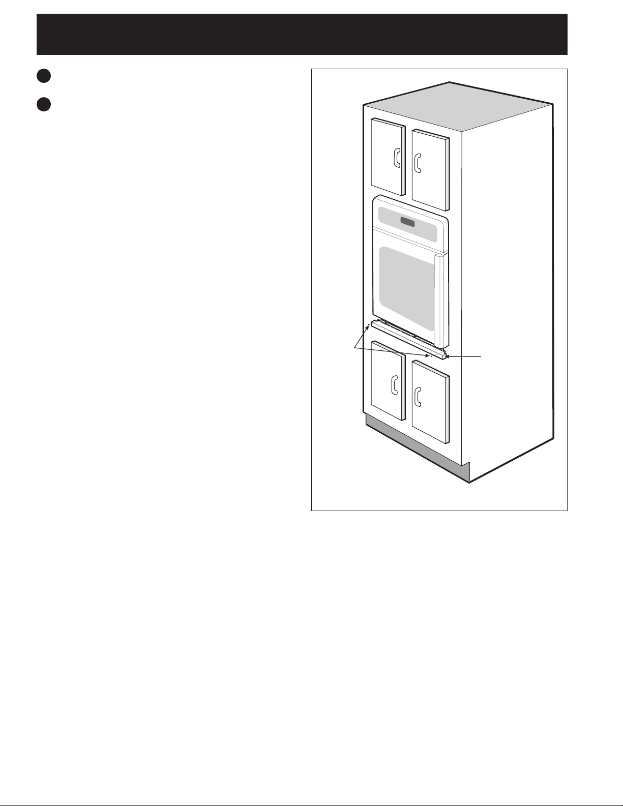
5
Push the oven in and against the cabinet.
6
Bottom Trim Installation:
For a cutout height (H) greater than 28¼" (71,7
cm) you can order a larger bottom trim, contact a
Service Center.
Place the top of the bottom trim over the side trim
tabs on each side of the oven below the oven
doorandxitusingthe2screwssuppliedinthe
mounting holes located on each side trim below the
ovenframe(seegure17).
Screws
supplied
Bottom
Trim
Figure 17
8
ELECTRIC WALL OVEN INSTALLATION INSTRUCTIONS
(and Optional Electric or Gas Cooktop Combination)
For typical under counter installation of an electric built-in oven see Figure below.
Only certain cooktop models may be installed
over certain built-in electric oven models.
Approved cooktops and built-in ovens are listed
by the MFG ID number and product code (see the
insert sheet included in the literature package and
cooktop installation instructions for dimensions).
Approx. 3"
(7,5 cm)
To reduce the risk of
personal injury and
tipping of the wall
oven, the wall oven
must be secured to
the cabinet (s) by
mounting screws.
G
Cabinetsidellerpanels
are necessary to isolate the
unitfromadjoiningcabinets.
Cabinetsidellerheight
should allow for installation of
approved cooktop models
H
36" Min.
(91,4 cm) Min.
208/240Voltjunctionbox
for built-in oven.
* If no cooktop is installed directly
over the oven unit, 5" (12,7 cm)
maximum is allowed above the
oor.
F
Use 3/4" (1,9 cm) plywood, in-
stalledontworunners,ushwith
toe plate. Base must be capable
of supporting 150 pounds (68 kg).
Cut an opening in wood base minimum 9" x 9"
(23X23cm),2"(5cm)fromleftsidellerpanel,
toroutearmoredcabletojunctionbox.
4 1/2" (11,5 cm) Max.*
CUTOUT DIMENSIONS
F. WIDTH G. DEPTH H. HEIGHT
7
24
/8" (63,2 cm) Min.
25¼" (64,1 cm) Max. 28¼" (71,7 cm) Max.
24" (61,0 cm) Min.
27¼" (69,2 cm) Min.
Figure 18- TYPICAL UNDER COUNTER INSTALLATION OF A SINGLE ELECTRIC BUILT-IN OVEN
WITH AN ELECTRIC COOKTOP MOUNTED ABOVE
9
 Loading...