

Frigidaire FGEF306TM, FGEF306TMB, FGEF306TMF, FGEF306TMW Install Manual
30" ELECTRIC RANGE INSTALLATION INSTRUCTIONS
29-7/8”
25-3/4”
49”
Maximum
42”
Door open
30”
36 1/8”
INSTALLATION AND SERVICE MUST BE PERFORMED BY A QUALIFIED
INSTALLER. IMPORTANT: SAVE FOR LOCAL ELECTRICAL INSPECTOR'S
USE. READ AND SAVE THESE INSTRUCTIONS FOR FUTURE REFERENCE.
FOR YOUR SAFETY: Do not store or use gasoline or other
United States
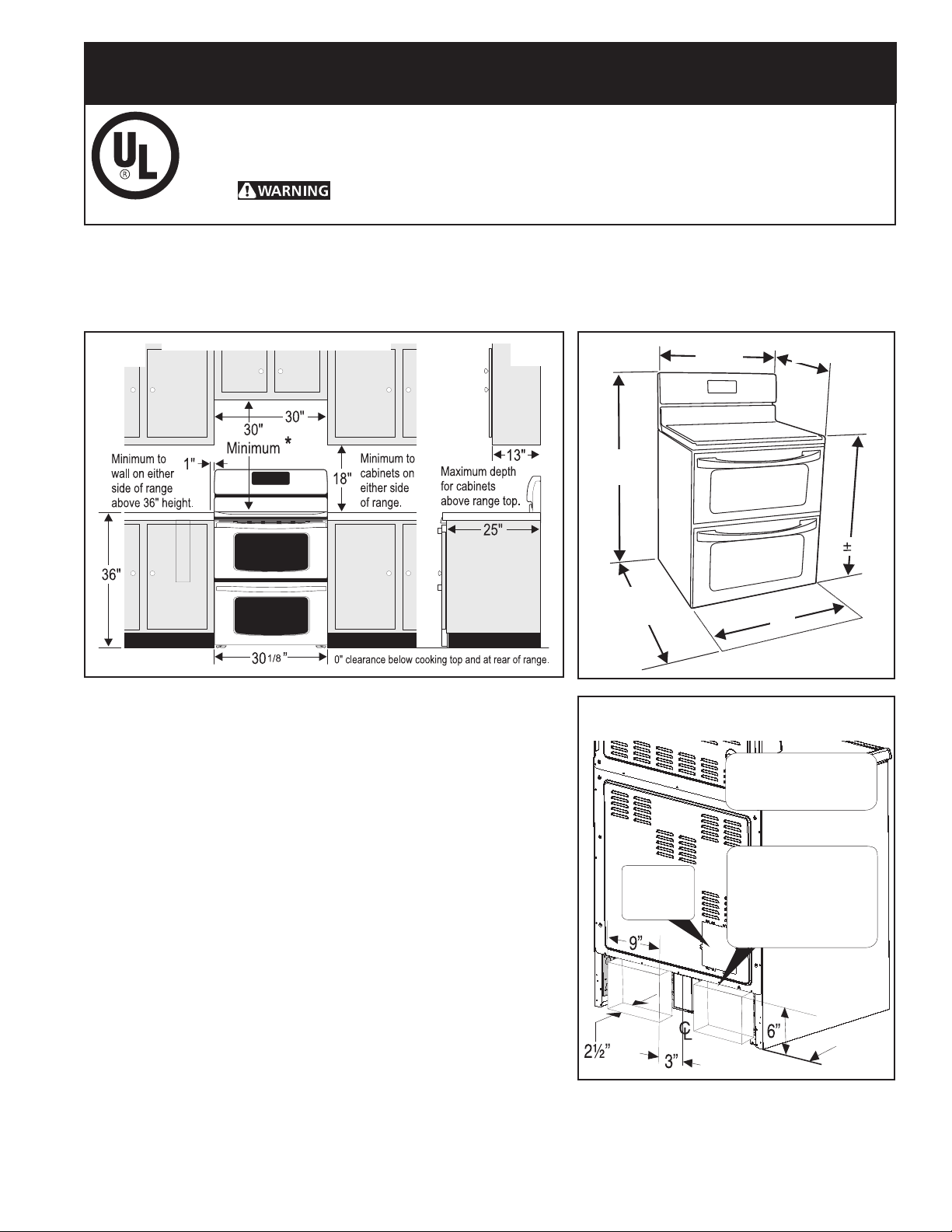
1. Clearances and Dimensions
a. Provide adequate clearances between the range and adjacent combustible surfaces.
b. Location—Check location where the range will be installed. Check for proper electrical supply and the stability of floor.
c. Dimensions that are shown must be used. Given dimensions provide minimum clearance. Contact surface must
be solid and level.
FRONT
VIEW
TYPICAL CABINET INSTALLATION
flammable vapors and liquids in the vicinity of this or any other appliance.
SIDE
VIEW
FRONT
VIEW
* 30" minimum clearance between the top of the cooking surface
and the bottom of an unprotected wood or metal cabinet; or 24 "
minimum when bottom of wood or metal cabinet is protected by not
less than ¼" flame retardant millboard covered with not less than
no. 28 MSG sheet steel, 0.015" stainless steel, 0.024" aluminum
or 0.020" copper. The minimum clearance is 0" for the rear of the
range. Follow all dimension requirements provided above to prevent
property damage, potential fire hazard, and incorrect countertop
and cabinet cuts.
Avoid locating cabinet storage space above the surface units
to eliminate the possibility of cabinets catching on fire, or
personal burns from reaching for the cabinets over the heated
units. If cabinet storage is to be provided, risk can be reduced by
installing a range hood that projects horizontally a minimum of
5" beyond the bottom of the cabinets.
Terminal
Block
Location
All dimensions for
electrical outlet
location are maximum.
Cubed area shows
where the electrical
outlet must be
installed for the
range to be flush to
the wall.
BACK
VIEW
Important Notes to the Installer
1. Read all instructions contained in these installation instructions
before installing the appliance.
2. Remove all packing material before connecting the electrical
supply to the appliance.
3. Observe all governing codes and ordinances.
4. Be sure to leave these instructions with the consumer.
Important Note to the Consumer
Keep these instructions with your Use and Care Guide for future reference.
Printed in Canada 318201729 (1108) Rev. B
1
Wall
Edge
30" ELECTRIC RANGE INSTALLATION INSTRUCTIONS
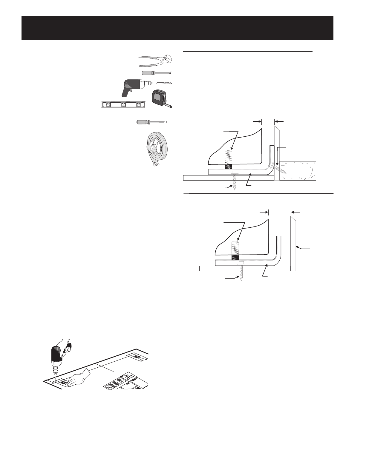
FASTEN BRACKET (WALL OR FLOOR MOUNTING)
FASTEN BRACKET (FLOOR MOUNTING ONLY)
Leveling leg
Wall mount
Floor Mount
Anti-Tip Bracket
Rear of Range
1-1/4” Max.
Wall Plate
Wall
More than
1-1/4”
Leveling leg
Floor Mount
Anti-Tip Bracket
Rear of Range
2. Tools You Will Need
For leveling legs and Anti-Tip Bracket:
• Adjustable wrench or channel lock pliers
• 5/16" Nutdriver or Flat Head Screwdriver
• Electric Drill & 1/8" Diameter
Drill Bit (Masonry Drill Bit if
installing in concrete)
• Level & Measuring Tape
For electrical supply connection:
• 1/4" & 3/8" Socket driver or Nutdriver
Additional Materials You Will Need:
• Power Supply Cord or
• Copper Electrical Wiring & Metal
Conduit (for hard wiring)
3. Anti-tip Bracket Installation Instructions
Important Safety Warning
To reduce the risk of tipping of the range, the range must be
secured to the floor by the properly installed anti-tip bracket
and screws packed with the range. Failure to install the antitip bracket will allow the range to tip over if excessive weight
is placed on an open door or if child climbs upon it. Serious
injury might result from spilled hot liquids or from the range
itself.
B. Drill Pilot Holes and Fasten Bracket - Drill
a 1/8" pilot hole where screws are to be located. If
bracket is to be mounted to the wall, drill pilot hole at
an approximate 20° downward angle. If bracket is to be
mounted to masonry or ceramic oors, drill a 3/16" pilot
hole 1-3/4" deep. The screws provided may be used in
wood or concrete material. Use a 5/16" nut-driver or at
head screwdriver to secure the bracket in place.
If range is ever moved to a different location, the anti-tip
brackets must also be moved and installed with the range.
Instructions are provided for installation in wood or
cement floor. When fastening to floor, be sure that
screws do not penetrate electrical wiring or plumbing.
A. Locate the Bracket Using the Template - Locate
the bracket position (right or left side) by placing the
template symmetrically to the center of the final range
position. Mark the location of the screw holes, shown on
template.
Figure 1
Figure 2
2
30" ELECTRIC RANGE INSTALLATION INSTRUCTIONS
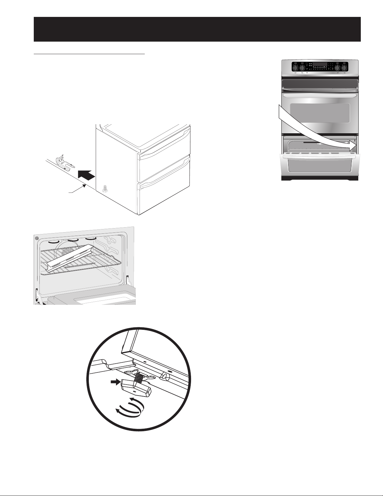
Range side
Slide
range
back
C. Level and position the range -
its final position. Insert the range leveling leg in the anti-tip
bracket. Visually verify if the anti-tip bracket is engaged.
Lower the range by adjusting the 4 leveling legs alternatively
until the range is level. Check if the range is level by placing
a spirit level on the oven rack. Take 2 readings with the spirit
level placed diagonally; take a reading in one direction and
then in the other direction. Level the range if necessary by
adjusting the leveling legs.
Slide range to
Figure 3
4. Serial Plate Information
The serial plate is
located as shown.
See the serial plate
for the following
information:
A. Model, lot and serial
number of range.
B. Kilowatt rating (power
requirements).
C. Voltage ratings.
Figure 5
Figure 4
Leg
Leveler
Raise
Lower
Figure 5
3
30" ELECTRIC RANGE INSTALLATION INSTRUCTIONS
5. Electrical Connection Requirements
This appliance must be properly installed and
grounded by a qualified technician in accordance with
the National Electrical Code ANSI/NFPA No. 70--latest
edition--and local electrical code requirements.
This appliance may be connected by means of
permanent "Hard Wiring" or "Power Supply Cord Kit."
When hard wiring, do not leave excess wire in range
compartment. Excess wire in the range compartment
may not allow the access cover to be replaced
properly, and could create a potential electrical hazard
if wires become pinched. When using flexible conduit
or range cable, use flex connector or range cable strain
relief.
NOTE: Only use copper wire in connection to terminal
block.
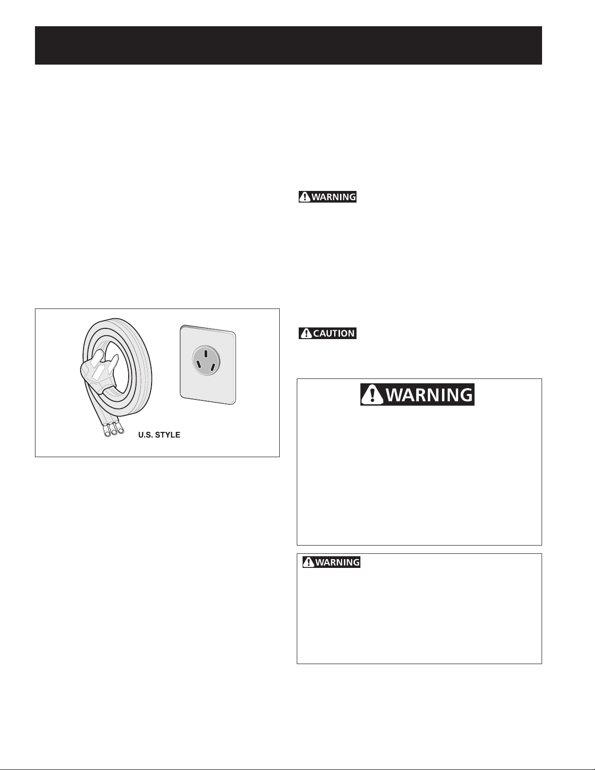
5.1 Models Requiring Power Supply Cord Kit
The user is responsible for connecting the power supply cord
to the connection block located behind the back panel access
cover.
This appliance may be connected by means of permanent
"hard wiring"; flexible armored or nonmetallic shielded copper
cable (when local code allow it) or by means of a power
supply cord kit.
NOTE: Electric Slide-in Range is shipped from factory with 1
1/8" (2.9 cm) dia. hole as shown on gure 4. If a larger hole is
required, punch out the knockout.
Risk of fire or electrical shock exists if
an incorrect size range cord kit is used, the Installation
Instructions are not followed, or the strain relief bracket
is discarded.
For mobile homes, new installations or recreational vehicles,
use only a power supply kit designed for a range at
125V/250V 50A recommended (minimum 40A). Cord must
have either 3 (when local code permits grounding through
neutral) or 4 conductors. Terminal on end of wires must be
either closed loop or open spade lug with upturned ends.
Cord must have strain-relief clamp. If a 50A circuit is used, a
50A power cord must be used.
Do not loosen the nuts which secure the
factory-installed range wiring to terminal block while
connecting range. Electrical failure or loss of electrical
connection may occur.
3-Wire Cord Kit
Electrical Shock Hazard
• Electricalgroundisrequiredonthisappliance.
• Donotconnecttotheelectricalsupplyuntil
appliance is permanently grounded.
• Disconnectpowertothecircuitbreakerorfuse
box before making the electrical connection.
• Thisappliancemustbeconnectedtoagrounded,
metallic, permanent wiring system, or a grounding
connector should be connected to the grounding
terminal or wire lead on the appliance.
Failure to do any of the above could result in a fire,
personal injury or electrical shock.
This appliance is manufactured with
the frame grounded by connection of a grounding
strap between the neutral power supply terminal and
the frame. If used in USA, in a new branch circuit
installation (1996 NEC), mobile home or recreational
vehicule, where local code do not permit grounding
through neutral (white) wire or in Canada; remove the
grounding strap from the frame and cut the other end,
near the neutral terminal. Connect the appliance in
usual manner.
4
 Loading...