


Frigidaire FGC30S4AQC, FGC30S4ASC, FGC30S4DBA, FGC30S4DCA, FGC30S4DCB Installation Guide
INSTALLATION AND SERVICE MUST BE PERFORMED BY
A QUALIFIED INSTALLER.
IMPORTANT: SAVE FOR LOCAL ELECTRICAL INSPECTOR'S USE.
READ AND SAVE THESE INSTRUCTIONS FOR FUTURE REFERENCE.
_lf the information in this manual is not followed exactly, a fire or explosion may result
causing property damage, personal injury or death.
FOR YOUR SAFETY:
-- Do not store or use gasoline or other flammable vapors and liquids in the vicinity of this or any other
appliance.
-- WHAT TO DO IF YOU SMELL GAS:
• Do not try to light any appliance.
• Do not touch any electrical switch; do not use any phone in your building.
• Immediately call your gas supplier from a neighbor's phone. Follow the gas supplier's instructions.
• If you cannot reach your gas supplier, call the fire department.
-- Installation and service must be performed by a qualified installer, service agency or the gas supplier.
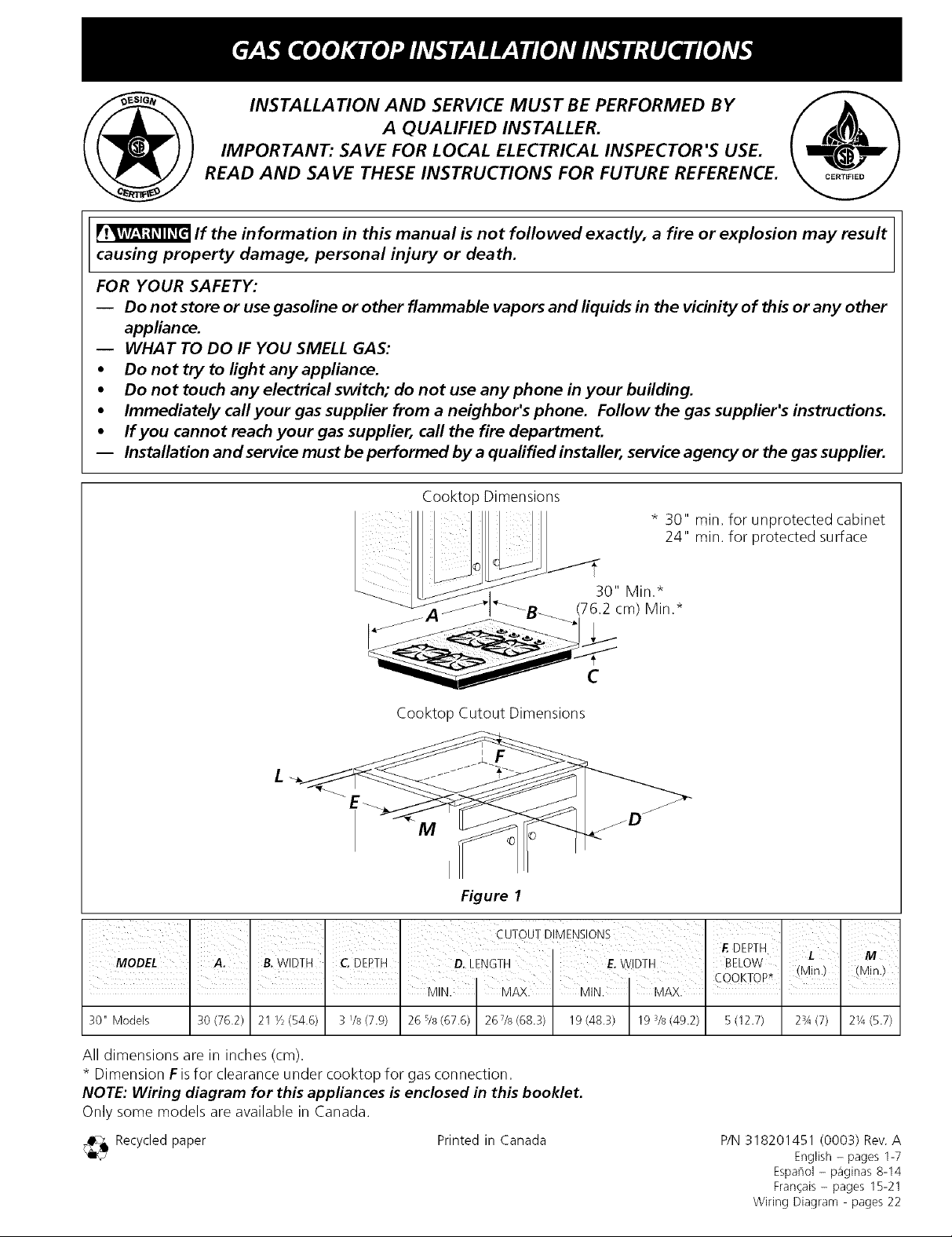
Cooktop Dimensions
* 30" min. for unprotected cabinet
24" min. for protected surface
C
Cooktop Cutout Dimensions
L
M
Figure 1
, , COOKTOP* (Min.) (Min.)
I I I I MIN. MAX. MIN. MAX. I I I
30" Models 30 (76.2) 21 1/2(54.6) 3 I/8 (7.9) 26 s/s(67.6) 267/8 (68.3) 19(48.3) 19 S/s(49.2) 5 (12.7) 2s4 (7) 21/4(5.7)
All dimensions are in inches (cm).
* Dimension F isfor clearance under cooktop for gas connection.
NOTE: Wiring diagram for this appliances is enclosed in this booklet.
Only some models are available in Canada
_ Recycled paper
Printed in Canada
P/N 318201451 (0003) Rev. A
English - pages 1-7
Espariol - p_iginas 8-14
Fran_ais - pages 15-21
Wiring Diagram - pages 22
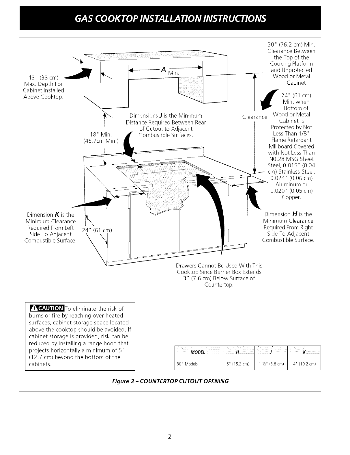
13" (33 cm)
Max. Depth For
Cabinet Installed
Above Cooktop.
18" Min.
(45.7cm Min.)
A Min.
Dimensions J isthe Minimum
Distance Required Between Rear
of Cutout to Adjacent
Combustible Surfaces.
Clearance
30" (76.2 cm) Min.
Clearance Between
the Top of the
Cooking Platform
and Unprotected
Wood or Metal
Cabinet
Min. when
24" (61 cm)
Bottom of
Wood or Metal
Cabinet is
Protected by Not
LessThan 1/8"
Flame Retardant
Millboard Covered
with Not LessThan
N0.28 MSG Sheet
Steel, 0.015" (0.04
cm) Stainless Steel,
0.024" (0.06 cm)
Aluminum or
0.020" (0.05 cm)
Copper.
Dimension K isthe
Minimum Clearance
Required From Left
Side To Adjacent
Combustible Surface.
24" (61 cm)
\
_To eliminate the risk of
burns or fire by reaching over heated
surfaces, cabinet storage space located
above the cooktop should be avoided. If
cabinet storage is provided, risk can be
reduced by installing a range hood that
projects horizontally a minimum of 5"
(12.7 cm) beyond the bottom of the
cabinets.
Dimension H isthe
Minimum Clearance
Required From Right
Side To Adjacent
Combustible Surface.
Drawers Cannot Be UsedWith This
Cooktop Since Burner Box Extends
3" (7.6 cm) Below Surface of
Countertop.
MODEL I H I J I K
30" Models 6" (15.2 cm) 1 _/2"(3.8 cm) 4" (10.2 cm)
Figure 2 - COUNTERTOP CUTOUT OPENING
Important Notes to the Installer
1. Read all instructions contained in these installation
instructions before installing the cooktop,
2. Remove all packing material before connecting the
electrical supply to the cooktop.
3. Observe all governing codes and ordinances,
4. Be sure to leave these instructions with the consumer.
Important Note to the Consumer
Keep these instructionswith your Use and Care Guide for
future reference.
IMPORTANT SAFETY
INSTRUCTIONS
Installation of this cooktop must conform with local codes
or, in the absence of local codes, with the National Fuel
Gas Code ANSI Z223.1--1atest edition in the United
States, or in Canada, with the Canadian Fuel Gas Code,
CAN/CGA B149 and CAN/CGA B149.2.
This cooktop has been design certified by American Gas
Association (A.G.A.). As with any appliance using gas
and generating heat, there are certain safety precautions
you should follow. You will find them in the Use and
Care Guide, read it carefully.
• Be sure your cooktop is installed and grounded
properly by a qualified installer or service
technician.
• This cooktop must be electrically grounded in
accordance with local codes or, in their absence,
with the National Electrical Code ANSI/NFPA No.
70--latest edition in the United States, or in
Canada, with the Canadian Electrical Code, CSA
C22.1 Part 1.
• The burners can be lit manually during an
electrical power outage. To light a burner, hold a
lit match to the burner head, then slowly turn the
Surface Control knob to LITE. Use caution when
lighting burners manually.
• Do not store items of interest to children in the
cabinets above the cooktop. Children could be
seriously burned climbing on the cooktop to reach
items,
• To eliminate the need to reach over the surface
burners, cabinet storage space above the burners
should be avoided.
• Adjust surface burner flame size so it does not
extend beyond the edge of the cooking utensil.
Excessive flame is hazardous,
• Never use your cooktop for warming or heating
the room. Prolonged use of the cooktop without
adequate ventilation car/ be hazardous.
• Do not store or use gasoline or other flammable
vapors and liquids near this or any other
appliance. Explosions or fires could result.
The electrical power to the cooktop
must be shut off while line connections are being
made. Failure to do so could result in serious
injury or death.
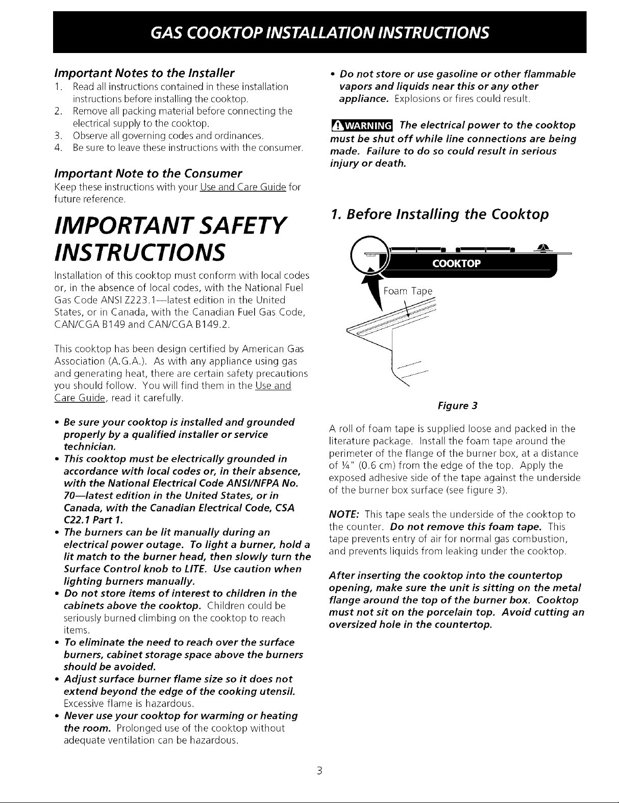
1. Before Installing the Cooktop
Foam Tape
Figure 3
A roll of foam tape is supplied loose and packed in the
literature package. Install the foam tape around the
perimeter of the flange of the burner box, at a distance
of ¼" (0.6 cm) from the edge of the top. Apply the
exposed adhesive side of the tape against the underside
of the burner box surface (see figure 3).
NOTE: This tape seals the underside of the cooktop to
the counter. Do not remove this foam tape. This
tape prevents entry of air for normal gas combustion,
and prevents liquids from leaking under the cooktop.
After inserting the cooktop into the countertop
opening, make sure the unit is sitting on the metal
flange around the top of the burner box. Cooktop
must not sit on the porcelain top. Avoid cutting an
oversized hole in the countertop.
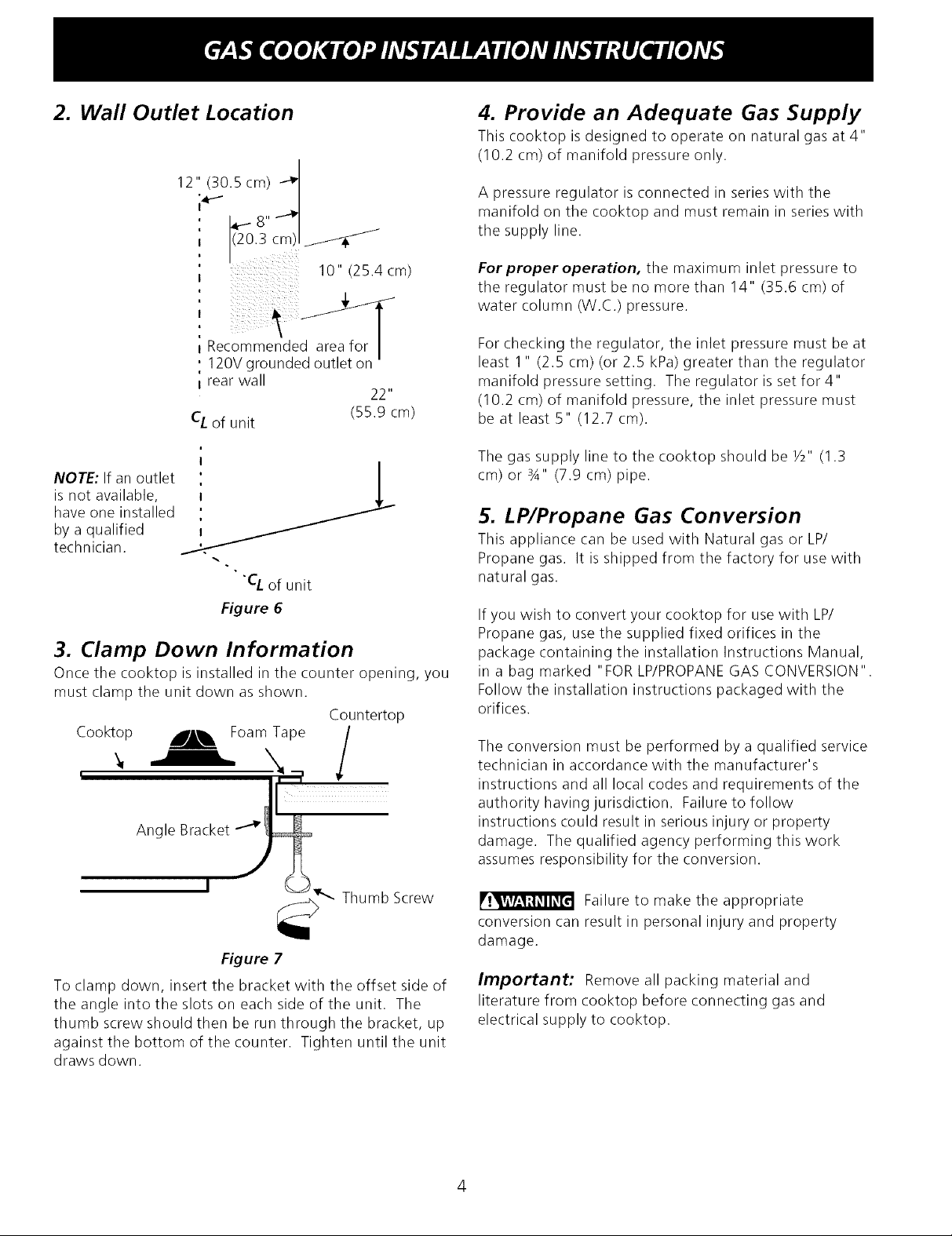
2. Wall Outlet Location
12" (30.5 cm)
14"" i_ 8,, d
I 1(20.3cm)l _1_ _/
4. Provide an Adequate Gas Supply
This cooktop isdesigned to operate on natural gas at 4"
(10.2 cm) of manifold pressure only.
A pressure regulator is connected in series with the
manifold on the cooktop and must remain in series with
the supply line.
10,,(254cm)
,',
Recommende
120V grounded outlet on '
i rear wall
22"
CL of unit (55.9 cm)
NOTE: If an outlet
is not available,
have one installed
by a qualified
technician.
"CL of unit
Figure 6
3. Clamp Down Information
Once the cooktop is installed in the counter opening, you
must clamp the unit down as shown.
Countertop
For proper operation, the maximum inlet pressure to
the regulator must be no more than 14" (35.6 cm) of
water column (W.C.) pressure.
For checking the regulator, the inlet pressure must be at
least 1" (2.5 cm) (or 2.5 kPa) greater than the regulator
manifold pressure setting. The regulator is set for 4"
(10.2 cm) of manifold pressure, the inlet pressure must
be at least 5" (12.7 cm).
The gas supply line to the cooktop should be Y2" (1.3
cm) or 3A" (7.9 cm) pipe.
5. LP/Propane Gas Conversion
This appliance can be used with Natural gas or LP/
Propane gas. It is shipped from the factory for use with
natural gas.
If you wish to convert your cooktop for use with LP/
Propane gas, use the supplied fixed orifices in the
package containing the installation Instructions Manual,
in a bag marked "FOR LP/PROPANEGAS CONVERSION".
Follow the installation instructions packaged with the
orifices.
Figure 7
To clamp down, insert the bracket with the offset side of
the angle into the slots on each side of the unit. The
thumb screw should then be run through the bracket, up
against the bottom of the counter. Tighten until the unit
draws down.
The conversion must be performed by a qualified service
technician in accordance with the manufacturer's
instructions and all local codes and requirements of the
authority having jurisdiction. Failure to follow
instructions could result in serious injury or property
damage. The qualified agency performing this work
assumes responsibility for the conversion.
Failure to make the appropriate
conversion can result in personal injury and property
damage.
Important: Remove all packing material and
literature from cooktop before connecting gas and
electrical supply to cooktop.
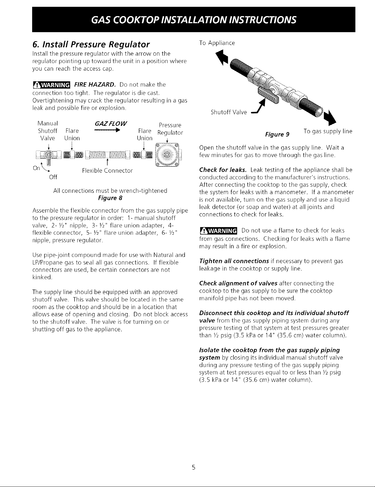
6. Install Pressure Regulator
Install the pressure regulator with the arrow on the
regulator pointing up toward the unit in a position where
you can reach the access cap.
FIRE HAZARD. Do not make the
connection too tight. The regulator is die cast.
Overtightening may crack the regulator resulting in a gas
leak and possible fire or explosion.
Manual GAZFIOI/V Pressure
Shutoff Flare _ Flare Regulator
Valve Union Union _,
+ 1 1
To Appliance
Shutoff Valve
Figure 9
Open the shutoff valve in the gas supply line. Wait a
few minutes for gas to move through the gas line.
To gas supply line
On_ Flexible Connector
Off
All connections must be wrench-tightened
Figure 8
Assemble the flexible connector from the gas supply pipe
to the pressure regulator in order: 1- manual shutoff
valve, 2- 1/2" nipple, 3- 1/2" flare union adapter, 4-
flexible connector, 5- 1/2"flare union adapter, 6- 1/2"
nipple, pressure regulator.
Use pipe-joint compound made for use with Natural and
LP/Propane gas to seal all gas connections. If flexible
connectors are used, be certain connectors are not
kinked.
The supply line should be equipped with an approved
shutoff valve. This valve should be located in the same
room as the cooktop and should be in a location that
allows ease of opening and closing. Do not block access
to the shutoff valve. The valve is for turning on or
shutting off gas to the appliance.
Check for leaks. Leak testing of the appliance shall be
conducted according to the manufacturer's instructions.
After connecting the cooktop to the gas supply, check
the system for leaks with a manometer. If a manometer
is not available, turn on the gas supply and use a liquid
leak detector (or soap and water) at all joints and
connections to check for leaks.
Do not use a flame to check for leaks
from gas connections. Checking for leaks withaflame
may result in a fire or explosion.
Tighten all connections if necessary to prevent gas
leakage in the cooktop or supply line.
Check alignment of valves after connecting the
cooktop to the gas supply to be sure the cooktop
manifold pipe has not been moved.
Disconnect this cooktop and its individual shutoff
valve from the gas supply piping system during any
pressure testing of that system at test pressures greater
than 1/2psig (3.5 kPa or 14" (35.6 cm) water column).
Isolate the cooktop from the gas supply piping
system by closing its individual manual shutoff valve
during any pressure testing of the gas supply piping
system at test pressures equal to or less than 1/2psig
(3.5 kPa or 14" (35.6 cm) water column).
7. Connect Electricity to Gas
Cooktop
Electrical Requirements
120 volt, 60 Hertz, properly grounded branch circuit
protected by a 15 amp circuit breaker or time delay fuse.
Do not use an extension cord with this cooktop.
8. Check Operation
Refer to the Use and Care Guide packaged with the
cooktop for operating instructions and for care and
cleaning of your cooktop.
Do not touch the burners. They may be hot enough to
cause burns.
IMPORTANT Please read carefully.
For personal safety, this appliance must be properly
grounded.
The power cord of this appliance is equipped with a 3-
prong (grounding) plug which mates with a standard 3-
prong grounding wall receptacle (see Figure 8) to
minimize the possibility of electric shock hazard from the
appliance.
The wall receptacle and circuit should be checked by a
qualified electrician to make sure the receptacle is
properly grounded.
Preferred Method
_Do not, under any"_+
_'__Uor_Set,anc;Syp_aUts' :
the grounding
Grounding
type wall
receptacle
__ _ prong. J
|_W Power supply cord with
_ 3-prong ground ng pug
Figure 10
Where a standard 2-prong wall receptacle is installed, it
is the personal responsibility and obligation of the
consumer to have it replaced by a properly grounded 3-
prong wall receptacle.
Do not, under any circumstances, cut or remove the
third (ground) prong from the power cord.
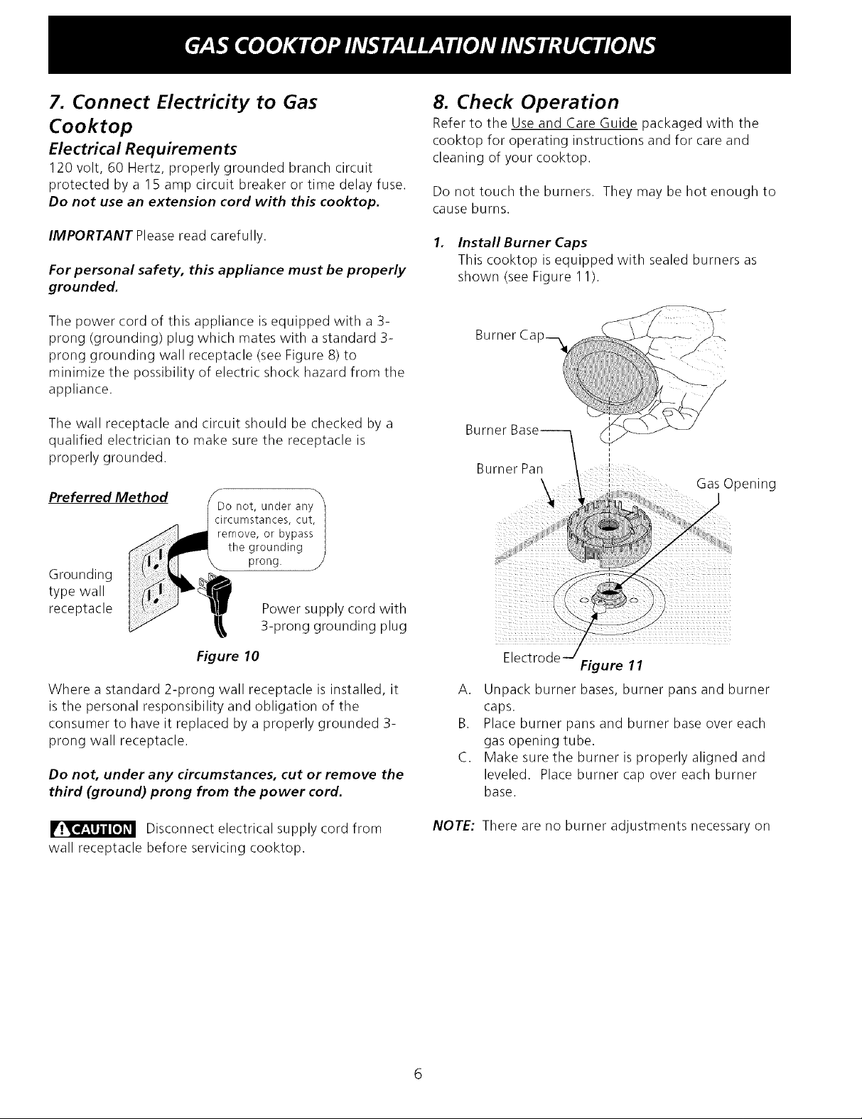
1. Install Burner Caps
This cooktop is equipped with sealed burners as
shown (see Figure 11).
Burner Base--.
i
3urner Par /
\
i
J
Gas Opening
k
Electrode --/
A.
Unpack burner bases, burner pans and burner
caps.
B.
Place burner pans and burner base over each
gas opening tube.
C.
Make sure the burner is properly aligned and
leveled. Place burner cap over each burner
base.
Figure 11
Disconnect electrical supply cord from
wall receptacle before servicing cooktop.
NOTE:
There are no burner adjustments necessary on
this cooktop.
2. Turn on Electrical Power and Open Main Shutoff
Gas Valve
3.
Check the Igniters
Operation of electric igniters should be checked after
cooktop and supply line connectors have been
carefully checked for leaks and the cooktop has
been connected to electric power.
To operate the surface burner:
A. Push in and turn a surface burner knob to the
LITEposition. You will hear a little ticking noise;
this isthe sound of the electric ignitor which
lights the burner.
B. After the burner lights, turn to the desired flame
size. The controls do not have to be set ata
particular mark. Use the marks as a guide and
adjust the flame as needed.
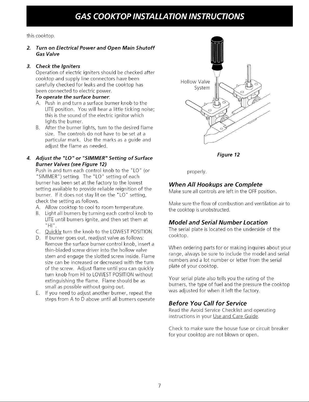
4.
Adjust the "LO" or "SIMMER" Setting of Surface
Burner Valves (see Figure 12)
Push in and turn each control knob to the "LO" (or
"SIMMER") setting. The"LO" setting of each
burner has been set at the factory to the lowest
setting available to provide reliable reignition of the
burner. If it does not stay lit on the "LO" setting,
check the setting as follows.
A. Allow cooktop to cool to room temperature.
B. Light all burners by turning each control knob to
LITEuntil burners ignite, and then set them at
"HI".
C. Quickly turn the knob to the LOWEST POSITION.
D. If burner goes out, readjust valve asfollows:
Remove the surface burner control knob, insert a
thin-bladed screw driver into the hollow valve
stem and engage the slotted screw inside. Flame
size can be increased or decreased with the turn
of the screw. Adjust flame until you can quickly
turn knob from HI to LOWEST POSITIONwithout
extinguishing the flame. Flame should be as
small as possible without going out.
E. If you need to adjust another burner, repeat the
steps from A to D above until all burners operate
\ /
Hollow Valve
System
Figure 12
properly.
When All Hookups are Complete
Make sure all controls are left inthe OFFposition.
Make sure the flow of combustion and ventilation air to
the cooktop isunobstructed.
Model and Serial Number Location
The serial plate is located on the underside of the
cooktop.
When ordering parts for or making inquires about your
range, always be sure to include the model and serial
numbers and a lot number or letter from the serial
plate of your cooktop.
Your serial plate also tells you the rating of the
burners, the type of fuel and the pressure the cooktop
was adjusted for when it left the factory.
Before You Ca//for Service
Read the Avoid Service Checklist and operating
instructions in your Use and Care Guide.
Check to make sure the house fuse or circuit breaker
for your cooktop are not blown or open.
LA INSTALACION Y EL SERVICIO DEBEN SER REALIZADOS POR UN
INSTALADOR CALIFICADO.
IMPORTANTE: GUARDE ESTAS INSTRUCCIONES PARA USO DEL
INSPECTOR ELECTRICO LOCAL.
LEA Y GUARDE ESTAS INSTRUCCIONES PARA FUTURAS
Si todas las instrucciones de este manual no son observadas a la letra, se puede ocurrir
incendios o explosiones que pueden causar dahos materiales, lesiones o la muerte.
PARA SU SEGURIDAD:
-- No almacene o utilice gasolina u otros vapores y liquidos inflamables cerca de este o cualquier otro
artefacto.
-- QUE HACER Sl HA YFUGAS DE GAS_
• No intente de encender ningun artefacto
• No toque ningun interruptor electrico; no utilice ningun aparato telefonico en su edificio.
• Llame inmediatamente el abastecedor de gas desde el telefono de un vecino. Siga las instrucciones del
abastecedor de gas.
• En caso que no puede contactar el abastecedor de gas Ilame al departamento de bomberos.
-- La instalacion y el servicio telefonico deben ser realizados por un instalador calificado, por un servicio
tecnico certificado o por el abastecedor de gas.
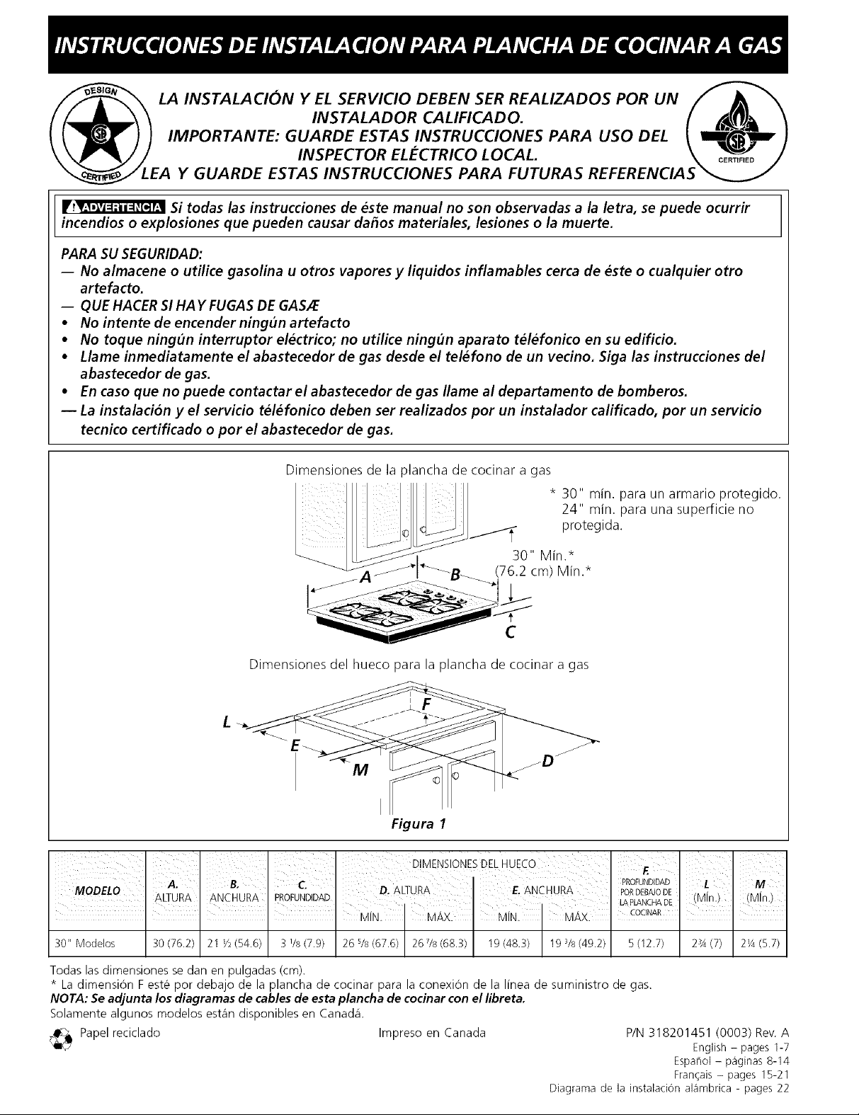
Dimensiones de la plancha de cocinar a gas
* 30" min. para un armario protegido.
24" min. para una superficie no
protegida.
30" Min.*
(76.2 cm) Min.*
C
Dimensiones del hueco para la plancha de cocinar a gas
M
Figura 1
30" Modelos 30 (76.2) 21 */_(54.6) 3 1/8(7.9) 26 s/s(67.6) 267/s (68.3) 19 (48.3) 19 3/8(49.2) 5 (12.7) 23A(7) 2'/4 (5.7)
Todas las dimensiones se dan en pulgadas (cm).
* La dimension F este por debajo de la plancha de cocinar para la conexion de la I[nea de suministro de gas.
NOTA: Se adjunta los diagramas de cables de esta plancha de cocinar con el libreta.
5olamente algunos modelos est_in disponibles en Canada1.
<_ Papel reciclado Impreso en Canada
Diagrama de la instalacion al_imbrica - pages 22
P/N 318201451 (0003) Rev. A
English - pages 1-7
Espahol - p_ginas 8-14
Fran_ais - pages 15-21