

Frigidaire FGB500CGBB, FGB500CGSB, FGB504CHBA, FGB504CHBB, FGB504CHSA Installation Guide
...
INSTALLATION AND SERVICE MUST BE PERFORMED BY
A QUALIFIED INSTALLER.
IMPORTANT: SAVE FOR LOCAL ELECTRICAL INSPECTOR'S USE.
READ AND SAVE THESE INSTRUCTIONS FOR FUTURE REFERENCE.
If the information in this manual is not followed exactly, a fire or explosion may result
causing property damage, personal injury or death.
FOR YOUR SAFETY:
m Do not store or use gasoline or other flammable vapors and liquids in the vicinity of this or any other
appliance.
-- WHAT TO DO IF YOU SMELL GAS:
• Do not try to light any appliance.
• Do not touch any electrical switch; do not use any phone in your building.
• Immediately call your gas supplier from a neighbor's phone. Follow the gas supplier's instructions.
• If you cannot reach your gas supplier, call the fire department.
-- Installation and service must be performed by a qualified installer, service agency or the gas supplier.
• Do not install wall oven beneath the work counter.
l Additional Safeguards
• The flue charge shall not be located below the 36" level.
42 3/s"
8
Model with 2 oven cavities Model with 11/zoven cavity
Clearance for complete door opening:
• For model with 2 cavities allow at least 17 5/8".
• For model with 1Y2cavity allow at least 19 3/8". Figure 1
<:xxxxxxxxxxxxxxxxxxxxxxxxxxxxxxxxxxxxxx:_<:xxxxxxxxxxxxxxxxxxxxxxxxx:_
Model with 2 cavities 19 Y2" Min.
2 Y2" Min. 24" Min. 16 3A" 7 1/8" 22 Y2" 24" Min. 42 1/8"
37 3/8"
B
H
A
Drill a lY2" diameter hole
for gas hook up
Electrical Outlet
Location for model
with lY_ oven
/ity
Electrical Outlet
Location for
- model with 2
oven cavities
_-_ T_
T 27"
Model wi_ 1Y2cavity 27 Y2" Max.
10" Min.
1 Y2" Min. 24" Min. 20" 7 s/8" 22" 23 Y2" Min.
NOTE: Wiring diagrams for these appliances are enclosed in this booklet.
_ Recycledpaper Printedin Canada
37 Y2" Min.
39" Max.
PIN 318201550 (0003) Rev. A
English - pages 1-8
Espa_ol - p4ginas 9-17
Wiring Diagram - pages 18-20
Important Notes to the Installer
1, Readall instructions contained in these installation
instructions before installing the appliance,
2, Remove all packing material and literature from the
oven and broiler compartments before connecting gas
and electric supply,
3, Observe all governing codes and ordinances,
4, Besure to leave these instructions with the consumer,
Important Note to the Consumer
Keep these instructions with your Useand Care Guide for
future reference,
Savethese instructions for local inspectors,
IMPORTANT SAFETY
INSTRUCTIONS
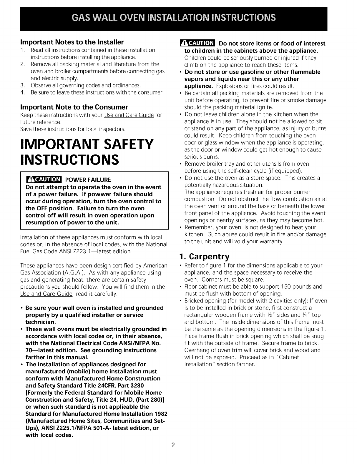
POWER FAILURE
Do not attempt to operate the oven in the event
of a power failure. If powwer failure should
occur during operation, turn the oven control to
the OFF position. Failure to turn the oven
control off will result in oven operation upon
resumption of power to the unit.
Installation of these appliances must conform with local
codes or, in the absence of local codes, with the National
Fuel Gas Code ANSI Z223,1--1atest edition,
These appliances have been design certified by American
Gas Association (AGA) As with any appliance using
gas and generating heat, there are certain safety
precautions you should follow You will find them in the
Use and Care Guide, read it carefully
• Be sure your wall oven is installed and grounded
properly by a qualified installer or service
technician.
• These wall ovens must be electrically grounded in
accordance with local codes or, in their absence,
with the National Electrical Code ANSI/NFPA No.
70mlatest edition. See grounding instructions
farther in this manual.
• The installation of appliances designed for
manufactured (mobile) home installation must
conform with Manufactured Home Construction
and Safety Standard Title 24CFR, Part 3280
[Formerly the Federal Standard for Mobile Home
Construction and Safety, Title 24, HUD, (Part 280)]
or when such standard is not applicable the
Standard for Manufactured Home Installation 1982
(Manufactured Home Sites, Communities and Set-
Ups), ANSI Z225.1/NFPA 501-A- latest edition, or
with local codes.
Do not store items or food of interest
to children in the cabinets above the appliance.
Children could beseriously burned or injured if they
climb on the appliance to reach these items
• Do not store or use gasoline or other flammable
vapors and liquids near this or any other
appliance. Explosions or fires could result
• Becertain all packing materials are removed from the
unit before operating, to prevent fire or smoke damage
should the packing material ignite
• Do not leave children alone in the kitchen when the
appliance is in use They should not be allowed to sit
or stand on any part of the appliance, as injury or burns
could result Keep children from touching the oven
door or glass window when the appliance is operating,
as the door or window could get hot enough to cause
serious burns
• Remove broiler tray and other utensils from oven
before using the self-clean cycle (if equipped)
• Do not use the oven as a store space This creates a
potentially hazardous situation
The appliance requires fresh air for proper burner
combustion Do not obstruct the flow combustion air at
the oven vent or around the base or beneath the lower
front panel of the appliance Avoid touching the event
openings or nearby surfaces, as they may become hot
• Remember, your oven is not designed to heat your
kitchen Such abuse could result in fire and/or damage
to the unit and will void your warranty
1. Carpentry
• Referto figure 1 for the dimensions applicable to your
appliance, and the space necessary to receive the
oven Corners must be square
• Floor cabinet must be able to support 150 pounds and
must be flush with bottom of opening
• Bricked opening (for model with 2 cavities only): If oven
isto be installed in brick or stone, first construct a
rectangular wooden frame with Y2"sidesand 1/4"top
and bottom The inside dimensions of this frame must
be the same as the opening dimensions in the figure 1
Placeframe flush in brick opening which shall be snug
fit with the outside of frame Secure frame to brick
Overhang of oven trim will cover brick and wood and
will not be exposed Proceed as in "Cabinet
Installation" section farther

2. Connect Electricity to Gas Wall
Oven
For personal safety, these appliances must be
properly grounded.
This appliance is equipped with a three-
prong grounding plug for your protection against shock
hazard and must be plugged directly into a properly
grounded receptacle Do not cut or remove grounding
prong from this plug
The wall receptacle and circuit should be checked by a
qualified electrician to make sure the receptacle is
properly grounded
Preferred Method
Grounding
type wall
receptacle
Power supply cord with
3-prong grounding plug
3. Alternate construction
(Model with 11/zoven cavity only)
Installation Instructions for installing a 11//2cavity oven into
an existing 2 cavity opening with dimensions 42 1/8" height
by 22 F2"Width
Figure 3
Figure 2
Where a standard 2-prong wall receptacle is installed, it
isthe personal responsibility and obligation of the
consumer to have it replaced by a properly grounded 3-
prong wall receptacle.
Do not, under any circumstances, cut or remove the
third (ground) prong from the power cord.
If an external electrical source is used, the appliance,
when installed, must be electrically grounded in
accordance with local codes or in their absence of local
codes with the National Electric Code ANSI/NFPA No.
70-1987 or latest edition.
Check all code rules and regulations for connecting the
wall oven to be certain the installation conforms with all
local, municipal and state codes as well as local utility
regulations.
Failure to comply with the above could result in a
serious shock hazard.
Note: All hookups and adjustments shall be performed
by qualified technicians.
1. Height adjuster- lower height adjuster 1".
2. If width opening istoo wide to secure unit to cabinet
with mounting screws, add filler strips.
3. 2" X 4" (standard 1 Y2" X 3 Y2") 22" minimum - stand
upright and flush with front cabinet. Secure to floor or
wall.
4. Lower trim (not shown)- overlap cabinet front (at
bottom ofcutout 1/4"minimum.
Disconnect electrical supply cord from
wall receptacle before servicing wall oven,
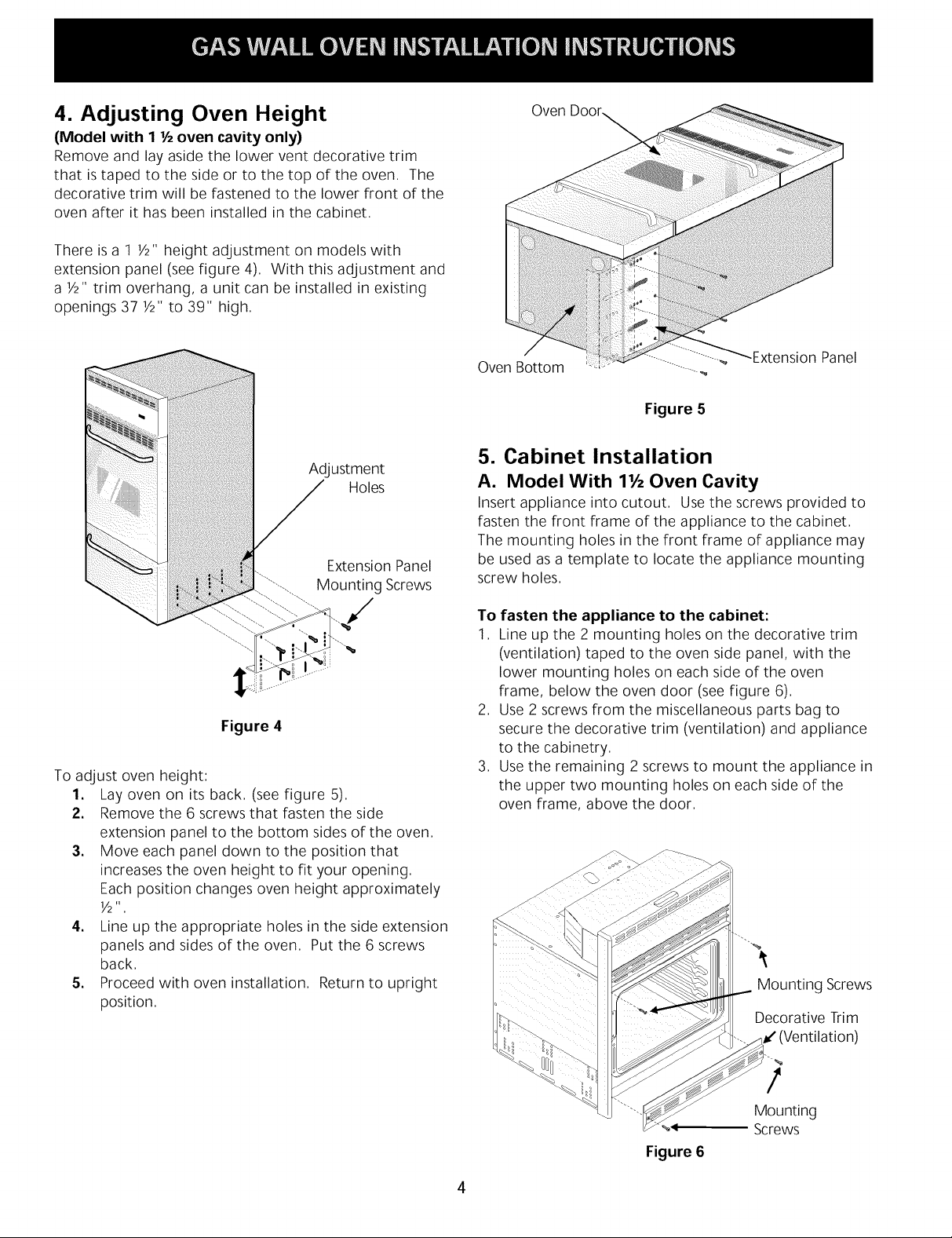
4. AdJusting Oven Height
(Model with 1 1/2oven cavity only)
Remove and lay aside the lower vent decorative trim
that is taped to the side or to the top of the oven The
decorative trim will be fastened to the lower front of the
oven after it has been installed in the cabinet
There is a 1 Y2" height adjustment on models with
extension panel (seefigure 4). With this adjustment and
a Y2" trim overhang, a unit can be installed in existing
openings 37 Y2" to 39" high.
Oven
Adjustment
Holes
Extension Panel
Mounting Screws
Figure 4
To adjust oven height:
1. Lay oven on its back (see figure 5)
2. Remove the 6 screws that fasten the side
extension panel to the bottom sides of the oven
3. Move each panel down to the position that
increases the oven height to fit your opening
Each position changes oven height approximately
]//2 _T ,
4. Line up the appropriate holes in the side extension
panels and sides of the oven Put the 6 screws
back
5. Proceed with oven installation Return to upright
position
Oven Bottom
Figure 5
Panel
5. Cabinet Installation
A. Model With lYz Oven Cavity
Insert appliance into cutout. Use the screws provided to
fasten the front frame of the appliance to the cabinet.
The mounting holes in the front frame of appliance may
be used as a template to locate the appliance mounting
screw holes.
To fasten the appliance to the cabinet:
1 Line up the 2 mounting holes on the decorative trim
(ventilation) taped to the oven side panel, with the
lower mounting holes on each side of the oven
frame, below the oven door (see figure 6)
2 Use 2 screws from the miscellaneous parts bag to
secure the decorative trim (ventilation) and appliance
to the cabinetry
3 Use the remaining 2 screws to mount the appliance in
the upper two mounting holes on each side of the
oven frame, above the door
Mounting Screws
Decorative Trim
_"(Ventilation)
!
_4
Figure 6
4
Mounting
Screws

B. Model With 2 Oven Cavities
Insertappliance into cutout, The unit must be secured in
place, Use the 2 screws provided in the miscellaneous
parts bag, for mounting the appliance in the mounting
holes on each side trim aside the central vent trim (figure
7),
",..%
Mounting
Screws
Ca
Remove Screw_:::_
B1 Vent Pipe
"]_ 4"I,D,
II It °D
Pipe to be A.._II II
tight to flue ._.____11
collar
Figure 8
7. Provide an Adequate Gas Supply
Important: Read these instructions carefully before
connecting this unit to a gas supply,
Figure 7
6. Externally Vented Installations
Model With 2 Oven Cavities only
IMPORTANT: Refer to the serial plate for information on
type of venting, if marked vented, see proper instructions.
NOTE: In some areas, outside venting is required or
preferred. For specified models with outside venting
provided (see specification sheet), use the following
instructions for proper installation of outside venting.
Vent pipe must be mechanically fastened to flue collar.
1. Before the oven is placed in the cabinet opening:
A. Remove knockout on the top cover of the unit and
bend tab up at right angle to the coven
B. Remove the cap that covers the vent by removing the
screw.
2. Ease the oven into opening.
A. Place the pipe on the vent outlet and drill a 3/32"
diameter hole at point "A" (see figure 8). Hole must
be drilled so that holes in pipe and flue collar line up.
B. Fasten the pipe to flue collar with one screw. (see
figure 8).
In order to fasten pipe to flue collar, it will be neces-
sary to move control panel out of the way and reach
in to drive screw.
Maintain minimum 1" clearance between the vent pipe
and surrounding combustible surfaces as stated on serial
plate.
The units covered in these instructions are designed to
operate on natural gas at 4" of manifold pressure or on
LPgas at 10" of manifold pressure,
A convertible pressure regulator is connected in series
with the manifold of the wall oven unit and must remain
in series with the supply line, regardless of which type of
gas is being used,
For proper operation, the maximum inlet pressure to
the regulator must not exceed 14" of water column
(W,C,) pressure,
To check the regulator, the inlet pressure must be at
least 1" (or 3,4 kPa) greater than the regulator manifold
pressure setting, If the regulator is set for 4" of manifold
pressure, the inlet pressure must be at least 5", If the
regulator isset for 10", the inlet pressure must be at
least 11",
A manual shut-off valve must be installed on the gas
supply line external to the unit and where it can be
easily reached for the purpose of turning the gas to the
unit on and off,
The gas supply line to the unit should be 1/2"(1,3 cm) or
3/4" (1,9 cm) pipe,
To avoid pilot outage (if applicable) close all openings in
the cabinet cavity that encloses this unit, All openings
around gas service outlets must be closed at the time of
installation,
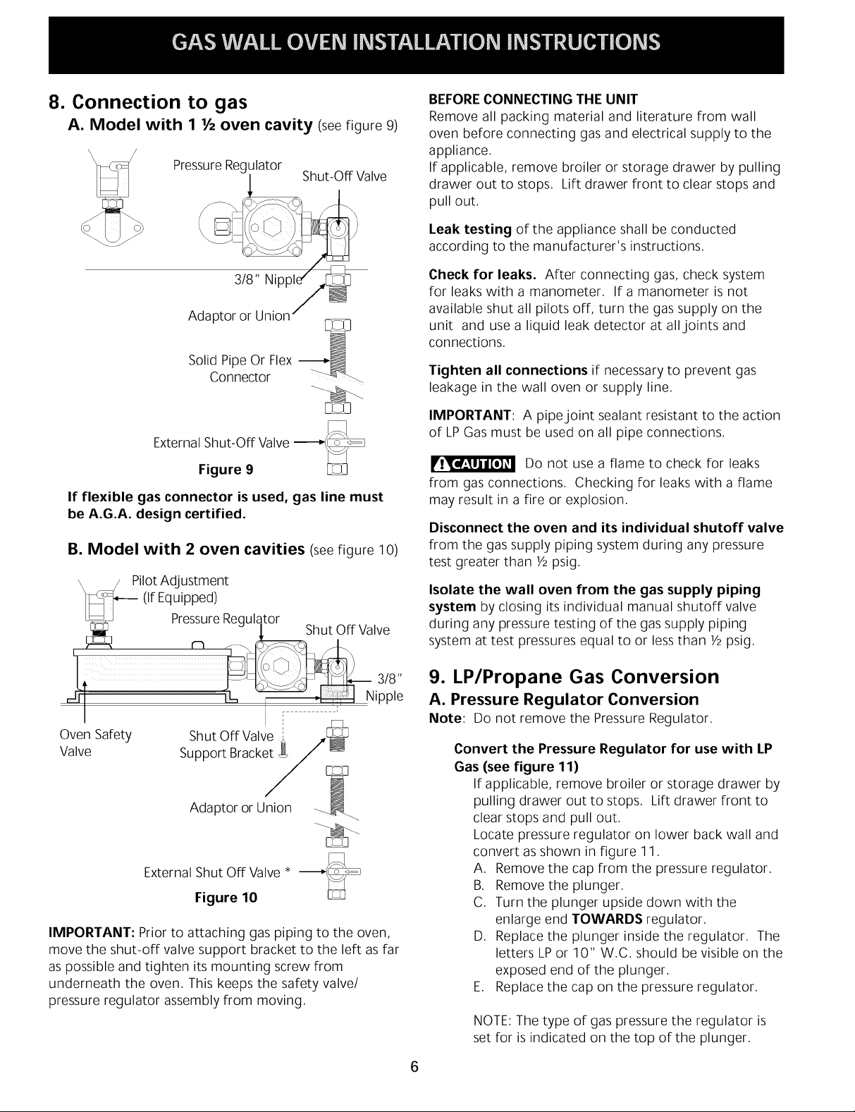
8. Connection to gas
A. Model with 1 Vzoven cavity (seefigure 9)
PressureRegulator
BEFORECONNECTING THE UNIT
Remove all packing material and literature from wall
oven before connecting gas and electrical supply to the
appliance,
If applicable, remove broiler or storage drawer by pulling
drawer out to stops, Lift drawer front to clear stops and
pull out,
Valve
Adapro;/8'; _i'_'/_
Solid Pipe Or Flex -_
Connector
External Shut-Off Valve
Figure 9
If flexible gas connector is used, gas line must
be A.G.A. design certified.
B. Model with 2 oven cavities (seefigure 10)
\ / PilotAdjustment
]_::_--- (IfEquipped)
L_ PressureRegula,tor ........
_C _ bnut urr vawe
Leak testing of the appliance shall be conducted
according to the manufacturer's instructions,
Check for leaks. After connecting gas, check system
for leaks with a manometer. If a manometer is not
available shut all pilots off, turn the gas supply on the
unit and use a liquid leak detector at all,joints and
connections.
Tighten all connections if necessary to prevent gas
leakage in the wall oven or supply line,
IMPORTANT: A pipe joint sealant resistant to the action
of LPGas must be used on all pipe connections,
Do not use a flame to check for leaks
from gas connections. Checking for leaks with a flame
may result in a fire or explosion.
Disconnect the oven and its individual shutoff valve
from the gas supply piping system during any pressure
test greater than Y2psig,
Isolate the wall oven from the gas supply piping
system by closing its individual manual shutoff valve
during any pressure testing of the gas supply piping
system at test pressures equal to or lessthan Y2psig,
ipple
I
Oven Safety
Valve
External Shut Off Valve * -_-_
IMPORTANT: Prior to attaching gas piping to the oven,
move the shut-off valve support bracket to the left as far
as possible and tighten its mounting screw from
underneath the oven. This keeps the safety valve/
pressure regulator assembly from moving.
Shut Off Valve
Support Bracket
Adaptor or Union
Figure 10
i
9. LP/Propane Gas Conversion
A. Pressure Regulator Conversion
Note: Do not remove the Pressure Regulator.
Convert the Pressure Regulator for use with LP
Gas (see figure 11)
If applicable, remove broiler or storage drawer by
pulling drawer out to stops. Lift drawer front to
clear stops and pull out.
Locate pressure regulator on lower back wall and
convert asshown in figure 11.
A. Remove the cap from the pressure regulator.
B. Remove the plunger.
C. Turn the plunger upside down with the
enlarge end TOWARDS regulator,
D, Replace the plunger inside the regulator, The
letters LPor 10" W,C, should be visible on the
exposed end of the plunger,
E, Replace the cap on the pressure regulator,
NOTE: The type of gas pressure the regulator is
set for is indicated on the top of the plunger,
6

_ SMALL End Towards
For L,R Gas Figure 11
B. Adjust Oven Burner Orifice
(see figure 12) Pin
Air Shutter
Using a Y2"wrench, turn down the adjustable spud
which injects gas into the oven burner. Spud
approximately 2Y2turns until snug against the LP
metering pin. Do not overtighten (see figure 13).
10. Natural Gas Conversion
Convert the Pressure Regulator for use with
Natural Gas (see figure 11)
A. Remove the cap from the pressure regulator.
B. Remove the plunger.
C. Turn the plunger upside down with the
enlarge end UP.
D. Replace the plunger inside the regulator. The
letters NAT or 4" W.C. should be visible on
the exposed end of the plunger.
E. Replace the cap on the pressure regulator.
F. Turn the valve hoods approximately 2 1/2
turns counterclockwise. This will move the
hood away from the mixer pin.
G. Apply gas, adjust pilots and burner air shutter
for proper flame.
H. There should be 4" WC pressure in the
manifold after conversion for proper operation
on Natural Gas.
ovoo
Spud 12
Using a Y2"wrench, turn down the adjustable spud
which injects gas into the oven burner, Spud
approximately 2Y2turns until snug against the LP
metering pin, Do not overtighten (see figure 12),
C. Adjust Broiler Burner Orifice (Self-Cleaning
Models Only) (see figure 13) Pin
)ud
Air Shutter
11. Adjustments
Oven/Broiler Flame Adjustment
The air shutter adjustment is located on the venturi tube,
which sets on the hood of the valve, and is locked in
place with a Phillips head screw. If the air shutter needs
adjusting, loosen the screw and rotate the shutter to
allow more or lessair to the burner tube (seefigure 14).
)_ Loosen
Air Adjustment
Shutter
Figure 14
For Natural Gas, the air shutter should be approximately
half open. For LPGas, the air shutter nearly full open.
Too much air will cause the flame to lift awya from the
burner, Too little air will cause the flame to turn yellow
at the outer edges and soot to form,
Figure 13
Waist-High
Broiler Spud
Remember, the oven will be shipped from the factory set
for Natural Gas, unless otherwise stated. If connecting
to LPgas, be sure to follow procedure under
"Conversion" to change the regulator and burner orifice
to the LPsetting.

Observetheovenburnerflameto determineifit isright.
Itshouldbesteadywithablueconeapproximately1"
andshouldnotextendoutovertheedgesofbaffle.For
LPGas,thiswillmostlikelyoccurwhentheair
adjustmentshutteriscompletelyopen(seefigure15).
TurnOvenTemperatureto 300°Fandallowoventocycle
onandoff.
Model and Serial Number Location
The serial plate is located on the left side inner trim of
the oven for the model with 1 Y2oven cavity and on the
lower oven frame for the model with 2 oven cavities.
When ordering parts for or making inquires about your
wall oven, always be sure to include the model and
serial numbers and a lot number or letter from the serial
plate of your appliance.
Your serial plate also tells you the rating of the burners,
the type of fuel and the pressure the wall oven was
adjusted for when it left the factory.
Stepping, leaning or sitting on the
oven door or drawer can result in serious injuries
and also cause damage to the appliance.
Be sure to keep appliance clear of combustible
materials, gasoline and other flammable vapors and
liquids.
Figure 15
To replace broiler drawer or lower bottom, reverse steps
taken for removal. Replace oven rack and/or broiler
pan.
12. Check Operation
Refer to the Use and Care Guide packaged with the wall
oven for operating instructions and for care and cleaning
of your appliance.
Do not touch the oven burner. They may be hot enough
to cause burns.
.
Check the Igniters (some models)
Operation of electric igniters should be checked after
oven and supply line connectors have been carefully
checked for leaks and oven has been connected to
electric power.
.
Oven Igniter System
Close the door and turn the Oven Temperature to
300°F, In approximately 60 seconds, the burner
should ignite and stay on until oven reaches 300°F,
Burner should then cycle on and off to maintain an
average temperature of approximately 300°F,
Before You Call for Service
Read the Avoid Service Checklist and operating and
cleaning instructions in your Useand Care Guide.
Check to make sure the house fuse or circuit breaker for
your wall oven is not blown or open.
Care, Cleaning and Maintenance for Wall
Ovens
If removing the wall oven is necessary for cleaning or
maintenance, shut off gas supply, Disconnect the gas
and electric supply, Remove the installation screws from
front frame and lower trim, Pull out only as far as
necessary to disconnect the electric supply line, After
disconnecting the gas and electric supply, finish
removing the unit for servicing and cleaning, Reinstall in
reverse order making sure to level the appliance; check
gas connection for leaks,
When All Hookups are Complete
Make sure all controls and programmable timer are left in
the OFFposition.
Resetall controls to the "OFF" position after using a
programmable timing operation.
8

LA INSTALACION Y EL SERVICIO DEBEN SER REALIZADOS POR UN
INSTALADOR CALIFICADO.
IMPORTANTE: GUARDE ESTAS INSTRUCCIONES PARA USO DEL
INSPECTOR ELI_CTRICO LOCAL.
.EA Y GUARDE ESTAS INSTRUCCIONES PARA FUTURAS REFERENCIAS
Si todas las instrucciones de este manual no son observadas a la letra, se puede ocurrir
incendios o explosiones que pueden causar dahos materiales, lesiones o la muerte.
PARA SU SEGURIDAD:
-- No almacene o utilice gasolina u otros vapores y liquidos inflamables cerca de este o cualquier otro
artefacto.
-- QUE HACER SI HAY FUGAS DE GASA_
• No intente de encender ningt_n artefacto
• No toque ningt_n interruptor electrico; no utilice ningt_n aparato telefonico en su edificio.
• Llame inmediatamente el abastecedor de gas desde el telefono de un vecino. Siga las instrucciones del
abastecedor de gas.
• En caso que no puede contactar el abastecedor de gas Ilame al departamento de bomberos.
m La instalacion y el servicio telefonico deben ser realizados por un instalador calificado, por un servicio
tecnico certificado o por el abastecedor de gas.
Medidas de seguridad adicionales
• No instale horno de pared debajo de la mesa de trabajo.
• La salida de descarga no debe estar por debajo de 36" de altura
Ubicacion de toma de
corriente electrica para
modelos con 1 Y_"
cavidad de homo
Ubicacion de toma de
corriente electrica para
modelos con 2 cavidades
de homo.
42 3/8"
B
r_23 3_
H
37 3/8"
38 el
23 W32
Modelos con 2 cavidades de horno.
Espacio libre para abrir completamente la puerta:
Para modelos con 2 cavidades de homo deje por Io menos 17 5/8"
Para modelos con 1 Ya cavidad de homo deje por Io menos 19 318"
Modelos con
125 3/8
Y2cavidad de horno.
Figura 1
Modelos con 2 cavidades 19 Y2" Min.
Modelos con I Y_cavidad
10" Min.
27 Y2" Max.
2 Y2" Min. 24" Min. 16 3A" 7 1/8" 22 Y2" 24" Min. 42 1/8"
1 Y2" Min. 24" Min. 20" 7 s/8" 22" 23 Y2" Min.
NOTA: Se adjunta el diagrama de cables de este horno con el catalogo.
_ Papelreciclado Impresoen Canada
A
D
Perforaci0n de 1 Y_" para
conexion de gas
37 Y2" Min.
39" Max.
PIN 318201550 (0003) Rev. A
English - pages 1-8
Espar_ol- p4ginas 9-17
Diagrama de la instalacion al4mbrica - paginas 18-20

Notas importantes para el instalador:
1. Leatodas las instrucciones de instalacion antes de
realizar la instalacion de la plancha de cocinar.
2. Retiretodos losarticulos de embalaje antes de realizar
lasconexiones electricas a la plancha de cocinar.
3. Observetodos los codigos o reglamentos estatales
4. Asegurese que el consumidor tenga estasinstrucciones.
Notas importantes para el consumidor
Guarde todas las instrucciones con su manual del usuario
para futuras referencias.
INSTRUCCIONES DE
SEGURIDAD IMPORTANTES
llr_ _j_tm=_'_j_ CORTE DE ENERG|A ELI_CTRICA
No trate de usar el horno de encendido electrico
durante un corte de energia. En caso de un
corte de energia electrica coloque todos los
controles en posicion apagado (OFF). El
restablecimiento del servicio electrico cuando los
controles del horno estan en cualquier posicion
diferente a APAGADO causaria el encendido
automatico del quemador del horno.
La instalacion de este horno empotrado a gasdebe
realizarse en conformidad con los codigos locales o, si
estos no existen, con el National Fuel Gas Code ANSI
Z223.1 - ultima edicion.
Eldiseho de este horno empotrado a gas cuenta con la
aprobacion de la American Gas Association (A.G.A.). AI
igual que todos los artefactos a gas que generan calor,
deben seguirse ciertas medidas de seguridad. Vienen con
el Manual del Usuario. Lea atentamente el manual.
• Asegdrese que el horno empotrado sea instalada
y puesta a tierra correctamente por un instalador
o tecnico calificado.
• El horno empotrado a gas debe conectarse
electricamente a tierra de acuerdo con los codigos
locales o, de no existir, con el codigo electrico
ANSI/NFPA No. 70 - dltima edicion.
• La instalacion de unidades dise_adas para casas
(movibles) deben cumplir con los estandares de
"Manufactured Home Construction and Safety Stan-
dard, title 24 CFR part 3280". Anteriormente "The
Federal Standard for Mobile Home Construction and
Safety title 24. HUD (Part 280)". O cuando estos
estandares no sean aplicables: "The Standard for
Manufactured Home Installation 1982,
(Manufactured Home Sites, Communities and set-
ups), ANSI Z225. NFPA - 501 A", ultima edicion o co-
digos y regulaciones locales.
No almacene alimentos u otros objetos
de interes para los ni_os en alacenas ubicadas
encima de la estufa o en la guarda posterior de
esta. Los nihos pueden quemarse o lastimarse
seriamente si se suben en la estufa para alcanzar estos
objetos.
• No guarde o haga uso de gasolina o otros vapores
y liquidos inflamables acerca de este o cualquier
aparato. Se puede resultar en incendios o
explosiones.
• Asegurese de remover todo el material de embalaje
del aparato antes de hacerlo funcionar, para evitar
fuego o dahos por humo, en caso que el material de
embalaje se encendio.
• No permita que los nihos esten solos en la cocina
cuando la estufa este en uso. No les permita sentarse
o pararse en ninguna parte de la estufa, pues podrian
lastimarse o quemarse. Asegurese de que no toquen
la puerta del horno o la ventana de vidrio cuando el
horno este en uso, ya que estas partes se calientan Io
suficiente como para causar quemaduras serias.
• Remueve la bandeja del asador y otros utensilios antes
de usar el ciclo de limpieza a si mismo.
• No use el horno como espacio de almacenamiento.
Esasituacion puede ser peligrosa.
• Laestufa requiere aire fresco para que el quemador
haga la combustion adecuadamente. No obstruya la
circulacion de aire de combustion en las ventilaciones
del horno, ni alrededor de la base, ni debajo del
tablero frontal de la estufa. Evite tocar las aberturas de
ventilacion y las superficies cercanas pues estas
pueden calentarse.
• Recuerde, su horno no ha sido disehado para calentar
la cocina. Esteabuso puede causar un incendio o daho
de la unidad y anularia la garantia.
1
• Carpinteria
Consulte la figura 1 para conocer las dimensiones
pertinentes al modelo de su horno y al espacio
necesario en el que poner el homo. Lasesquinas
deben estar cuadradas.
El piso del gabinete debe soportar una carga de 150
libras y debe estar nivelado con el fondo de la
abertura.
Abertura en ladrillo (para modelo con 2 cavidades del
mismo tamaho solamente): Si el horno va a ser
empotrado en ladrillo o piedra, construya primero un
marco rectangular de madera de 1/2"en las laterales y
V4"arriba y abajo. Lasdimensiones internas del marco
deben ser iguales a las dimensiones internas del marco
deben ser iguales a las dimensiones del esquema (22
Y2" X 42 %").
Coloque el marco nivelado y ajustado a la abertura en
el ladrillo. El sobreancho (pestaha) del horno cubrira el
marco de madera. Proceda como Io muestra el
siguiente esquema.
10

2. Conexion Electrica
Como medida de seguridad personal, este artefacto
debe conectarse a tierra correctamente.
!Ir_l_j_rm_ Parasu proteccion contra choques
electricos este aparato ha sido equipado con un enchufe
de tres paras con conexion a tierra apropiada. No
remueva la pata redonda de tierra de es enchufe.
Un electricista calificado debe verificar el enchufe de pared
y el circuito para asegurar que elenchufe esta conectado a
tierra correctamente.
3. Alternativa de construccion
(Para modelo con I 1/zcavidades solamente)
Instrucciones para instalar un horno de 1 Y2cavidades en
una abertura existente para horno de 2cavidades con
dimensiones de42 _/8" dealto por 22 Y2"de ancho.
42 _J
Metodo Preferido , bajo
Enchure
de pared a
tierra
Cable de encendido con
enchufe de tres
paras a tierra
Figura 2
Encaso de encontrarse con un enchufe de pared de dos
paras, es la personal responsabilidad y la obligacion del
consumidor reemplazarlo por el enchufe de pared a tierra
de tres paras correspondiente.
No debe, bajo ninguna circunstancia cortar o retirar la
tercera pata (tierra) del cable de encendido
Si una fuente de electrica es utilizada; el aparato debe
ser conectado a tierra de acuerdo con las normas locales
o de acuerdo las "National Electrical Code" ANSI/NFPA
No. 70-1987 o ultima edicion.
2"
Figura 3
1. Ajuste de altura - ajuste inferior de altura de 1".
2. Si la abertura es demasiado ancha para fijar la unidad
al gabinete con tornillos de montaje, ajuste con las
tiras de relleno.
3. 2" X 4" (1 Y2" X 3 Y2" standard) 22" minimo - para al
derecho, nivele con el frente del gabinete. Asegure al
suelo o al pared.
4. Moldura inferior (no se muestra) - monte al menos V4"
sobre el frente del gabinete (en parte inferior de
abertura).
Verifique todos los codigos, normas o regulaciones para
cerciorarse que la instalacion esta de acuerdo a los
codigos locales, estatales y de las empresas de servicio
de energia locales.
El incumplimiento las anteriores recomendaciones,
puede resultar en un peligroso coque electrico.
Nota: Todas las conexiones y ajustes deben de ser
realizados por un tecnico calificado.
Desconecte el cable del suministro
electrico del enchufe de pared antes de reparar la
plancha de cocinar.
11

4. Ajustando la Altura del Horno
(Para modelos con I Vzcavidades solamente)
Retire y ponga a un lado la rejilla baja de ventilacion que
esta pegada a la parte exterior del panel del horno. La
rejilla sera fijada a la parte de baja del frente del
gabinete despues de que este haya sido instalado en el
gabinete.
Estemodelos de horno cuenta con un ajuste de altura de 1
1/2"(ver figura 4). Con este ajuste y la pestaha de Y2" el
horno puede ser instalado en aberturas existentes de 37 Y2"
a 39" de altura.
Puerta del horno
Fondo del ...._ Panel de extension
homo
IFigura 5
Perferaciones
para
ajustar
Panel de
extension
tornillos de
IFigura 4
Paraajustar la altura del horno:
1. Coloque el horno sobre su parte posterior (ver
figura 5),
2. Remueva los 6 tornillos que aseguran el panel
lateral de extension a la partes laterales inferiores
del horno.
3. Mueva cada panel hasta la posicion que mejor
ajuste la altura del horno al tamaho de su
abertura. Cada posicion cambia la altura del
horno aproximadamente Y2"
4. Alinee los orificios del panel lateral de extension
con los de las paredes laterales del homo, Vuelva
a colocar los 6 tornillos.
5. Proceda con la instalacion del homo, Vuelva a
colocar el horno sobre su base.
5. Cabinet Installation
A. Model With Two Different Size Oven
Cavities
Introduzca el artefacto en el recortado, Lostornillos estan
provistos para fijar el armazon frontal del artefacto al gabi-
nete, Losagujeros de montadura en elarmazon frontal
pueden usarsecomo modelo para Iocalizar losagujeros
e
para lostornillos de montadura del artefacto.
Parafijar el artefacto a los gabinetes:
1. Alinee los dos agujeros de montadura en laparrilla con
losagujeros de montadura mas bajos en cada lado del
armazon del horno debajo de la puerta del horno (veafi-
gura 6).
2, Usedos tornillos de la bolsa de piezas miscelaneas para
fijar la parrilla y el artefacto a los gabinetes,
3, Uselos 2 tornillos restantes en los 2 agujeros de monta-
dura arriba en cada lado del armazon del horno, encima
da la puerta.
Tornillos de montaje
Rejilla para la
ventilacion
por abajo
12
_4
IFigura 6
Tornillos de
montaje

B. Modelo con 2 Cavidades
Introduzca el artefacto en el recortado. El
electrodomestico debe ser sujetado en su lugar. Utilice
los dos tornillos provistos en la bolsa de piezas varias
para montar el electrodomestico en los orificios de
montaje a cada lado de! armazon del horno, por encima
de la puerta (figura 7).
",.%
Capucha
Remuevatornillo-,-_::::_
I
[
B1 tubo de
ventilacion
"_ 4" I.D.
Tornillos de
montaje
Figura 7
6. Instalaciones ventiladas
exteriormente
Modelo con 2 Cavidades
IMPORTANTE: Refersirse a la placa de la serie para
informacion en el tipo de ventilacion. Si la ventilacion esta
marcada o especificada, ver las instrucciones pertinentes.
NOTA" En algunas zonas, la ventilacion al exterior es
requerida o preferida. Para modelos especificados con
ventilaciOn al exterior (ver hoja de especificaciones). Use
las siguientes instrucciones para una correcta instalaciOn de
la ventilacion al exterior. El tubo de ventilacion debe estar
mecanicamente amarrado al collar de salida. Ver detalle.
1. Antes de colocar el horno en la abertura:
A. Remueva el destapadero de la parte alta de la
cubierta y doble la pestaha en angulo recto con
respecto a la cubierta.
B. Remueva la tapa que proteje la ventilacion quitando
el tornillo.
2. Deslice el horno la abertura:
A. Coloque el tubo en la salida de la ventilaciOn y
taladre un hueco de 3/32" de diametro en el punto
"A" (ver figura 8). La perforaciOn en el tubo debe
ser hecha de manera que coincida con la de la salida
de la ventilacion.
B. Ajuste la tuberia de ventilacion a la salida de ventila-
cion con un tornillo (ver figura 8).
Para ajustar el tubo a la salida es necesario remover
el panel de controles para poder alcanzar el tornillo.
Guarde al menos 1" de margen libre entre la tuberia de
ventilacion y los elementos combustibles vecinos (como Io
establece la placa de serie)
TuboparaA,..IIII
fijar a salida -______U
de ventilacion
Figura 8
7. Provea un adecuado suministro de gas
Importante: Lea estas instrucciones cuidadosamente
antes de conectar esta unidad al suministro de gas.
Lasunidades alas cuales se refieren estas instrucciones
han sido disehadas para operar con gas natural de 4"
WC o gas LPde 10" WC.
Se conecta un regulador convertible de presion en serie al
multiple de el horno empotrado y debe permanecer en
serie con la linea de suministro de gas,
independientemente del tipo de gas que se este usando.
Para que manejo correcto, la presion de entrada
maxima hacia el regulador no debe exceder 14" (W.C.)
de presion de la columna de agua.
Paracontrolar el regulador, la presion de entrada debe ser
de al menos 1" (o 3.4 Kpa) mayor que el ajuste de la
presion del multiple del regulador. El regulador seajusta a
4" de la presion del multiple, la presion de entrada debe
de ser de al menos 5". El regulador se ajusta a 10" de la
presion del multiple, la presion de entrada debe de ser de
al menos 11".
Una valvula de corte manual externa a la unidad debe
instalarse en la linea de suministro de gas. El proposito
de esta valvula es poder abrir o cerrar al suministro de
gas a la unidad. Esta valvula debe estar Iocalizada en
un sitio de facil acceso para cerrar el suministro de gas a
la unidad.
La linea de suministro de gas por el plancha de cocinar
deberfa tener un tubo de Y2" o de 3/4"
13

Paraevitarqueelpilotoseapague(sipuedeaplicarse),
cierretodaslasaberturasdelacavidaddelgabineteque
encierralaunida,Tambiencualquieraberturaalrededor
delassalidasdelserviciodegasdebenestarcerradosen
elmomentodelainstalacion,
8. Conexion del gas
A. Modelo con 1 Vz cavidades (veafigura 9)
Regulador de presion Valvula de cierre
3/8" Ni
IMPORTANTE: Antes de conectar la tuberia de gas al
horno mueva la platina de soporte de la valvula de cierre
completamente hacia la izquierda y apriete el tornillo
que la sostiene desde debajo del homo, Esto asegura
que el ensamblaje del regulador de presion de la valvula
de seguridad no se mueva,
ANTES DE CONNECTAR ESTA UNIDAD
Retire todos los articulos de embalaje y folletos de el
horno empotrado antes de realizar las conexiones de gas
y electricas a el homo,
Si necesario, remueva al asador o el cajon de
almacenamiento hallandolo hacia afuera hasta los topes,
luego saque hacia afuera,
Verificar si hay fugas en el electrodomestico, la
verificacion debe de ser realizada segun las instrucciones
del fabricante.
Adaptor o Union
Tuber[a rigida o
conector flexible
Valvula exterior de cierre
LLU
Figura 9
Si se utiliza conectador de gas flexible, la linea
de gas debera ser de dise_o A.G.A. certificado.
B. Modelo con 2 cavidades (vea figura 10)
:_/._Adjuste de piloto (Sipuede aplicarse)
n
Regulad°r de presi' _al_t_de cierre
__ 3/8"
_i ..........................................................................................................i_ .I---_-I Niple
Valvula deseguridad Platina de
soporte de la
valvula de cierre [_
Verifique si hay fugas. Luego de conectar la cocina al
gas, verifique el sistema con un manometro. Si no cuenta
con este instrumento, de la vuelta al suministro de gas de
la cocina y utilice un detector de fugas liquidas (o agua y
jab0n) en todas las articulaciones y conexiones para
verificar siexisten fugas.
Ajuste todas las conexJones en caso que sea necesario,
para evitar fugas de gas en lacocina o en el tubo de
suministro de gas
IMPORTANTE: Para las uniones de tuberia debe usarse
un sellante de union de tuber[a que sea resistente a la
accion del gas LP.
No use ningun tipo de llama para
verificar si hay fugas de gas. Verifique si hay fugas con
una llama puede ocasionar incendio o explosion.
Desconecte el horno y su valvula de cierre individual
del sistema de tuber[a del suministro de gas durante
cualquier ensayo de presion del sistema en ensayos de
presion superiores a 1/2 psig (3,5 kPa o 14" colomna de
agua),
Aparte el horno del sistema de tuber|a del suministro
de gas cierrando su valvula de cierre individual manual,
durante cualquier ensayo de presion del sistema de
suministro de gasen ensayos iguales o inferiores a 1/2 psig
(3,5 kPao 14" colomna de agua),
Adaptor o Union
Valvula de corte manual externa _
Figure 10
14

9. ConversiOn de Gas Propano/
Licuado
A. Conversion del regulador de presion
Nota: No remueva el regulador de presion.
Convertir el regulador de presion para que se
pueda usar con Gas LP/Propano (vea figura 11)
Si necesario, remueva al asador o el cajon de
almacenamiento hallandolo hacia afuera hasta
los topes, luego saque hacia afuera.
Localice el regulador de presion en la parte
inferior de la pared trasera y modifique como se
muestra en la figura 11.
A. Remueva la tapa del regulador de presion.
B. Remueva el piston de la tapa.
C. De lavuelta al piston, poniendo la GRANDE
extremidad hacia el regulador.
D. Vuelva a poner el piston dentro de la tapa.
Las letras LPo 10" W.C. deben de estar
visibles en la extremidad descubierta del
piston.
E. Vuelva a poner la tapa del regulador.
NOTA: El tipo de presion de gas para el cual ha
sido calibrado el regulador esta indicado en la
parte superior del piston.
PEQUEI_A
extremidad hacia el
regulador para gas
unta
B. Ajuste del orificio del quemador del horno
(vea figura 12)
Pasador
k_unta en
Obturador deaire k
Junta enforma de
bellota del quemador
Figura 12
Usando una Ilave de Y2", giro hacia abajo lajunta en
forma de bellota ajustable que inyecta gas al quemador
del homo. Gire estajunta en forma de bellota hasta que
ajuste contra el pasador medidor de LP. Esto sera
aproximadamente 2 Y2vueltas. No Io apriete demasiado
(vea figura 12).
C. Ajuste del orificio del quemador del
asador (Modelos autolimpiadores solamente) (vea
figura 13)
Pasador
natural
GRANOEextremidad _ (_
hacia el regulador _
para Gas L.R
Figura 11
_ bellota
Ln forma
de bellota de la
parilla
Figura 13
Usando una Ilave de Y2", giro hacia abajo lajunta en
forma de bellota ajustable que inyecta gas al quemador
del homo. Gire estajunta en forma de bellota hasta que
ajuste contra el pasador medidor de LP. Esto sera
aproximadamente 2 Y2vueltas. No Io apriete demasiado
(vea figura 13).
15

10. Conversion de Gas Natural
Convertir la unidad de Gas LP/Propano a Gas
Natural, proceda de la siguiente manerar (vea
figura 11)
A. Remueva la tapa del regulador de presion.
B. Remueva el desatascador.
C. Gire el desatascador hacia arriba con el lado
grande hacia arriba.
D. Ponga el desatascador entre el regulador. Las
letras NAT o 4" WC deberan estar a la vista
en la parte expuesta del desatascador.
E. Colique la tapa en el vegulador.
F. Gire la capucha de la valvula
aproximadamente 2 1/2 vueltas en el sentido
contrario alas manecillas del reloj. Esto
separara la capucha del pasador mezclador.
G. Pasegas, ajuste los pilotos y el quemador
para obtener una llama conveniente.
H. Debera haber 4" WC de presion en el
multiple despues de este cambio para operar
propiamente con gas natural.
Use un manometro para chequear la presion en
el multiple, Si hay alguna duda. Recuerde la
presion de entrada debe ser al menos 1 " WC mas
alta que la presion de salida. La presion de
entrada en el regulador nunca debe exceder 14"
WC.
Para gas natural la entrada de aire debera estar
aproximadamente medio abierta. Para gas LP la entrada
de aire debera estar casi totalmente abierta.
Demasiado aire haria que la llama se alejara del
quemador. Una entrada insuficiente de aire causaria la
coloracion amarilla del borde externo de la llama yla
formacion de hollin.
Recuerde, el horno sera despacho de la fabrica
preparado para trabajar con gas natural, a menos que se
especifique algo diferente. Si se va a conectar a LPG35
aseg0rese de seguir el procedimiento indicado en
"Conversion" para cambiar el regulador y el orificio del
quemador a la ubicacion LP.
Para determinar si la llama del quemador del horno es la
apropiada, observe la llama. Esta debe estar estable
formando conos azules de 1" aproximadamente. La
llama no debe extenderse por encima de los bordes del
resonador. Paragas LP, esto ocurre mas frecuentemente
cuando el obturador de ajuste de aire esta
completamente abierto (vea figura 15).
Ponga el boron de OVEN TEMP (temperatura del horno)
en 300°F, y permita que el horno alterne entre "ON" y
"OFF" (prendido y apago).
11. Ajuste del la llama del quemador
del horno/asador
Ajuste el obturador de aire. Este Iocalizado en el
venturi, jundo a la capucha de la valvula yes fijado en
su lugar por un tornillo con cabeza tipo Phillips. Si este
necesita ajuste, afloje el tornillo y rota el obturador para
permitir mas o menos aire en el tubo del quemador.
(vea figura 14).
)4m FIojo
Obturador de ml_
aire
Figura 14
Figura 15
Para volver a colocar el cajon o el rondo inferior del
asador, siga en forma inversa los pasos tomados para
retirarlo. Vuelva a colocar la parrilla del horno y/o la
bandeja del asador.
16

12. Verifique la operacion
Refiera al Manual del Usuario que viene con el horno
empotrado para las instrucciones de funcionamiento y el
mantenimiento y la limpieza de su horno empotrado.
Asegurese de incluir el modelo, numero de serie y el
numero o letra de lore que se encuentran en la placa,
en todo pedido de partes o solicitud de informacion
acerca de su horno empotrado.
No toque a los quemadores. Pueden estar
suficientemente calientes par causar quemaduras.
1. Verifique los dispositivos de encendido
(algunos modelos)
La manipulacion de los dispositivos de encendido
electrico debera verificarse tras haber revisado
detenidamente el horno y los conectores del tubo del
suministro de fugas y tras haber conectado el horno al
suministro electrico.
2. Sistema de encendido del horno
Cierre la puerta del horno y gire el boron de OVEN TEMP
(temperatura del horno) a 300°F. En 60 segundos
aproximadamente, el quemador debe prender y
permanecer encendido hasta que el horno alcance
300°F. El quemador seguira alternando entre encendido
y apago para mantener una temperatura promedia de
aproximadamente 300°F.
Cuando se han realizado todos los sistema
de conexion
Asegurese que todos los controles estan en laposicion de
OFF (apagado).
Vuelva a colocar todos los controles en laposicion de
"OFF" (apagado) despues de utilizar el functionamiento de
programacion cronometrada.
Modelo y ubicacion del nt_mero de serie
La placa deserie esta ubicada al interior del contramarco
izquierdo del horno para modelos con 1 Y2cavidad de
horno yen el armazon de bajo del horno para modelos con
2 cavidades de homo.
La placa de numero de serie tambien indica las
especificaciones de los quemadores, el tipo de
combustible y la presion para la cual fue ajustada el
horno empotrado en lafabrica.
El apoyarse, pisarse o sentarse en
la puerta o en la gaveta de este horno puede
ocasionar graves heridas y tambien dahos a la
plancha de cocinar.
Asegtirese de no almanecer sobre o dentro el aparato
materiales inflamables, gasolina y otros liquidos
inflamables o latas en aerosol.
Antes de Ilamar al servicio tecnico
Lea la lista titulada "Evitando Llamadas de Servicio" y
las instrucciones de functionamiento en su Manual del
Usuario.
Verifique que los fusibles de la casa no se hayan fundido
o el cortocircuito del homo no haya saltado o abierto,
Cuidado, limpieza y mantenimiento
Cierre el suministro de gas en caso de ser necesario
remover la unidad para su limpieza o reparacion.
Desconecte la linea de suministro de gas. Remueva los
tornillos de instalacion del marco frontal y la parrilla
inferior. Hale hacia afuera apenas Io necesario para
poder desconectar del toma electrico. Despues de
desconectar del suministro electrico y de gas, termine de
remover la unidad para su limpieza o mantenimiento.
Reinstale siguiendo el procedimiento inverso. Asegurese
de nivelar la estufa y verificar que no halla escapes en la
conexion de gas.
17

CLOCK
RELOJ
WANNING,
DISCONNECTPOWER
BEFORE SERVICING UNIT,
AVISD,
_NECTE LA ENERGIA ANTES
DE REALIZAR EL MANTENIMIENTB
GEL ELEETRBDDNESTIEO
COLGR'dIRE NIl
NO, DE DOLOR DE ALANBNE
COLOR CODE
CDDIGDS lIE COLON
/ VER_E/C_IARILLI]RAXAS
®
BRO'dN/NGRENO
VIBLET/VlrI ETA
YELLB'd/ANARILL r
GRAY/GRAY
F._REEN/VERDE
RED/RDJB
PUNPLE/PURPUNA
nVEN LAMP SWITCH
INTERRUPTOR LUZ DE HORNO
®
_ ____ ENCENDI] OVEN VALVE
CONNECTOR
CDNECTOR
2 IB 299 3122
i IB 150 3321
WIRE GAGE UL STYLE
ALAMBRE HEOIOA ENP+C MODO UL
®
OVEN LAMP
LUZ DE HORNn
©
//J OVEN IGNITER
ENCENDID n DE HnRN n CONECTOR
[-_ VALVULA DE HORN.
THERMOSTAT
TERMOSTATO
CONNECTOR
CONECTOR
OVEN LAMP SWITCH
UNTERRUPTOR DE LUZ DE HORNO
OVEN LAMP
LUZ DE HDRNO
CONNECTOR
CDNECTDR
@
CLOCK
RELOJ
@
DEN L E
CONNECTOR
CONECTOR
_LVO_ _ HORNO
318046113 REV. A
GVEN THERMOSTAT
TE_DE HORNO
CONNECTOR
CDNECTOR
OVEN IGNITER
ENCENDIDD DE HDRNO
CAUTION.
LADEL ALL WIRES PRIOR TO DISCONNECTION WHEN SERVICING CONTROLS.
WIRING ERROR CAN CAUSE IMPROPER AND DANGEROUS OPERATION.
VERIFY PROPER OPERATION AFTER SERVICING.
AVISO,
ETIQUETE TODOS LOS ALAMBRES ANTES DE DESCONECTAR PAR REALIZAR EL
MANTENIMIENTO DE LOS CONTROLES.
ERROR DE ALAMBRAJE PUEDE CAUSAR UN FUNCIONAMIENTO INCORRECTO Y
PELIGRDSD.
VERIFIOUE SI EL FUNCIONAMIENTO ESTA CDRRECTD DESPUES DEL MANTENIMIENTO.
NOTE,
SERVICE,IF REPLACEMENT DF TERMINALS BECOMES NECESSAR_CDMPARABLE WIRE TYPE AND
GAGE AND COMPARABLE TERMINALS MUST BE USED.
NDTA=
EN CASO QUE SEA NECESARIO DE REEMPLAZAR LOS BORNES, ES NECESARIO DE UTILIZAR
EL MISMD TIPO DE ALAMBRE Y DE MEOIOOR Y EL MISMO TIPO DE BDRNES.

L N
DOOR SW[TCH
CONTROL BOARD
BL/W- I
mcO--..
NC
SEE LEGEND V- I
PROBE
0v- i
LEGEND :
A.D.S.
C NO BR
--o_____v-o
NC
m
I O m
20
30
4 O BK-I
50
6 0 w-1
7 O
CONTROLLER
J3
1 18 125 3173
o I
0-I
i 0 5
--J 04
3R-I
---03
v-1
o
0 6
02
01
Jl
LOCK MOTOR
CON
02
O SEE BELOW FOR CONNECTION
O5
O6
O 7 BROIL
NO BR LI
,E4 E6(b Eg(
_---
/
R-I
R-1
THERMAL
CIRCU]T
BREAKER
BK-1 4_ W-I
LATCH MOTOR
BROILIGNITERI a I
BL-I
0-1 Y-1
R-I
/
w- 1 -0 _- RELAY
R-1 _ GY-1
C NO
BK
SERVICE:
IF REPLACEMENT OF TERMINALB OR WIRING BECOME NECESSARY,
COMPARABLE WIRE TYPE, GAGE & TERMINALS MUST BE USED.
NOTE:
OVEN CONDITIONS:
ALL CONTROLB SET TO OFF
OVEN DOORS CLOSED & UNLDCNED. I 7 I o n A _ 7 _ A _,, n
COOL ]NG FAN
i
RELAY
OVEN LAMP
t
£//BK- I
BAKE I GN [ TER
<?) .-,
COOt_ ] NG FAN
_ w-1
OVEN LAMP
BAKE
BA GND
,)E7 E] E_,)
R-1
r l
[ 1
BEFORE SERVI CI NG UN[ T
TRACER WIRE:
VIRE COLORNOTED FIRST.STRIRS NEXT.
EXAMPLE :
RED _IRE WITH WHITE STRIPE.
BK BLACK P P INK
BL BLUE _ PURPLE
BR BROt,iN R RED
C COPPER T TAN
G GREEN V VIOLET
GoY GRAY "W "w'HI TE
W-1
W-1
W-I
£/ARN ING
BI SCONNECT PB_ER
Rig - I0
COLOR t41RE NO.
COLOR CODE
ORANGE Y YELLOk&
19

Ix.)
0
CLOCK
RELOJ
i
J
t
........ APPEAR ON ALL MODELS.
3 18
18
1 18
WIRE GAGE
ALAMBRE MEDIDA
OVEN
LAMP (I I;
LUZ DE_I._
HORNO y_
THESE COMPONENTS MAY NOT
ESTOS COMPONENTES ND PUEDEN
APARECER EN TODOS LOS MODELOS,
125 3173
125 3173
125 3173
UL STYLE
IEMP _C MOOD UL
OVEN LAMP
SWITCH
INTERRUPTBR DE
LUZ DE HORNO
BAKE VALVE
VALVULA DE
IGNITER CONECTOR DE
ENCENDIDO ENCENDIDO
POWER CORD
PARA TRANSPORTE
NNECTOR DE FUERZA
WARNING
DISCONNECT POWER
BEFORE SERVICING UNIT
AVISO
DESCONECTE LA ENERGIA ANTES
DE REALIZAR EL MANTENINIENTB
DEL ELECTRBDBMESTICB.
NO. DE COLOR DE ALAMBRE
COLOR CODE/CODIGOS DE COLOR
BK BLACK/NEGRO p PINK/ROSA
BL BLUE/AZUL PR PURPLE/PURPUREO
BR BROWN/MORENO R REDIROJO
C COPPER/COBRE T TAN/TOSTADO
O GREEN/VERDE V VIOLETIVIOLETA
GY GRAY/GRAY V WHITE/BLANCO
0 ORANGE/NARANJA y YELLOW/AMARILLO
i i
: _ IND.
:..... %_°!°____i
i
i
i
EAR
CULBR WIRE NU,
THERMOSTAT
TERMOSTATO
LALMApMAPRA 0
)_ SWITCH
INT. DE
LUZ DE
PUERTA
DOOR
LAMP
L
i
i
i
i
i
i
i
i
i
i
i
i
i
i
;z CONNECTOR
x CONECTOR
CLOCK
RELOJ
_4_DOOR LAMP SWITCH
INT. DE LUZ DE PUERTA
,F ........ -0_
i
i
OVEN LAMP SWITCH
INT, DE LUZ DE PUERTA
THERMOSTAT
TERMOSTATO
CAUTION=
LABEL ALL WIRES PRIOR TO DISCONNECTION WHEN
SERVICING CONTROLS,
WIRINGS ERROR CAN CAUSE IMPROPER AND
DANGEROUS OPERATION,
VERIFY PROPER OPERATION AFTER SERVICING.
AVISO=
ETIQUETE TODOS LOS ALAMBRES ANTES DE DESCONECTAR PAR
REALIZAR ET MANTENIMIENTO DE LOS CONTROLES,ERROR DE
ALAMBRAJE PUEDE CAUSAR UN FUNCIONAMIENTO INCORRECTO
Y PELIOROSO,VERIQUE SI EL FUNCIONAMIENTO ESTA
CORRECTB DESPUES DEL MANTENIMIENTB,
i
i
i
i
ID
i
BAKE IGNITER
ENCENDIDO DE HORNED
THESE COMPONENTS MAY NOT
APPEAR ON ALL MODELS.
ESTBS COMPONENTES NO PUEDEN
APARECER EN TODOS LOS MBDELBS,
OVEN LAMP
LUZ DE HORNO
IND. LAMP
LAMPARA PILOTO
VALVULA DE HORNED
CONNECTOR
CONECTOR
BAKE VALVE
N
L
318046306 REV: A
 Loading...